JP2004149556A - Method for gasifying biomass and gasifying apparatus therefor - Google Patents
Method for gasifying biomass and gasifying apparatus therefor Download PDFInfo
- Publication number
- JP2004149556A JP2004149556A JP2002312991A JP2002312991A JP2004149556A JP 2004149556 A JP2004149556 A JP 2004149556A JP 2002312991 A JP2002312991 A JP 2002312991A JP 2002312991 A JP2002312991 A JP 2002312991A JP 2004149556 A JP2004149556 A JP 2004149556A
- Authority
- JP
- Japan
- Prior art keywords
- biomass
- gas
- fluidized bed
- gasification
- fluidized
- Prior art date
- Legal status (The legal status is an assumption and is not a legal conclusion. Google has not performed a legal analysis and makes no representation as to the accuracy of the status listed.)
- Ceased
Links
Images


Classifications
-
- Y—GENERAL TAGGING OF NEW TECHNOLOGICAL DEVELOPMENTS; GENERAL TAGGING OF CROSS-SECTIONAL TECHNOLOGIES SPANNING OVER SEVERAL SECTIONS OF THE IPC; TECHNICAL SUBJECTS COVERED BY FORMER USPC CROSS-REFERENCE ART COLLECTIONS [XRACs] AND DIGESTS
- Y02—TECHNOLOGIES OR APPLICATIONS FOR MITIGATION OR ADAPTATION AGAINST CLIMATE CHANGE
- Y02E—REDUCTION OF GREENHOUSE GAS [GHG] EMISSIONS, RELATED TO ENERGY GENERATION, TRANSMISSION OR DISTRIBUTION
- Y02E20/00—Combustion technologies with mitigation potential
- Y02E20/16—Combined cycle power plant [CCPP], or combined cycle gas turbine [CCGT]
- Y02E20/18—Integrated gasification combined cycle [IGCC], e.g. combined with carbon capture and storage [CCS]
-
- Y—GENERAL TAGGING OF NEW TECHNOLOGICAL DEVELOPMENTS; GENERAL TAGGING OF CROSS-SECTIONAL TECHNOLOGIES SPANNING OVER SEVERAL SECTIONS OF THE IPC; TECHNICAL SUBJECTS COVERED BY FORMER USPC CROSS-REFERENCE ART COLLECTIONS [XRACs] AND DIGESTS
- Y02—TECHNOLOGIES OR APPLICATIONS FOR MITIGATION OR ADAPTATION AGAINST CLIMATE CHANGE
- Y02E—REDUCTION OF GREENHOUSE GAS [GHG] EMISSIONS, RELATED TO ENERGY GENERATION, TRANSMISSION OR DISTRIBUTION
- Y02E50/00—Technologies for the production of fuel of non-fossil origin
- Y02E50/30—Fuel from waste, e.g. synthetic alcohol or diesel
-
- Y—GENERAL TAGGING OF NEW TECHNOLOGICAL DEVELOPMENTS; GENERAL TAGGING OF CROSS-SECTIONAL TECHNOLOGIES SPANNING OVER SEVERAL SECTIONS OF THE IPC; TECHNICAL SUBJECTS COVERED BY FORMER USPC CROSS-REFERENCE ART COLLECTIONS [XRACs] AND DIGESTS
- Y02—TECHNOLOGIES OR APPLICATIONS FOR MITIGATION OR ADAPTATION AGAINST CLIMATE CHANGE
- Y02P—CLIMATE CHANGE MITIGATION TECHNOLOGIES IN THE PRODUCTION OR PROCESSING OF GOODS
- Y02P20/00—Technologies relating to chemical industry
- Y02P20/141—Feedstock
- Y02P20/145—Feedstock the feedstock being materials of biological origin
-
- Y—GENERAL TAGGING OF NEW TECHNOLOGICAL DEVELOPMENTS; GENERAL TAGGING OF CROSS-SECTIONAL TECHNOLOGIES SPANNING OVER SEVERAL SECTIONS OF THE IPC; TECHNICAL SUBJECTS COVERED BY FORMER USPC CROSS-REFERENCE ART COLLECTIONS [XRACs] AND DIGESTS
- Y02—TECHNOLOGIES OR APPLICATIONS FOR MITIGATION OR ADAPTATION AGAINST CLIMATE CHANGE
- Y02W—CLIMATE CHANGE MITIGATION TECHNOLOGIES RELATED TO WASTEWATER TREATMENT OR WASTE MANAGEMENT
- Y02W30/00—Technologies for solid waste management
- Y02W30/50—Reuse, recycling or recovery technologies
- Y02W30/78—Recycling of wood or furniture waste
Abstract
Description
【0001】
【発明の属する技術分野】
本発明は、家具や木工製品等の製造過程で発生する林産廃棄物(のこくず等の木質片や木質粉、間伐材等)、農産廃棄物(もみがら、稲わら、余剰産物等)、上下水廃棄物(夾雑物、糞尿残渣、下水汚泥等)、低品位石炭等のバイオマス資源を比較的低温下で炭化水素や水素、CO等にガス化して、発電用コジェネレーションシステム等へのエネルギー源や、肥料用等の有機合成製品の原料ガスとして提供できるバイオマスのガス化方法及びそのガス化装置に関する。
【0002】
【従来の技術】
バイオマス資源をエネルギーや原料ガスに変換する技術としては、エタノール発酵やメタン発酵法、加熱ガス化法などの方法があり、発酵方式は変換に時間がかかり実用的な運用が困難であるという欠点がある。
バイオマスに適用可能とされる加熱ガス化技術は、石炭ガス化技術が基本的に踏襲され、そのガス化反応炉の形状から以下に示す▲1▼固定床ガス化法、▲2▼噴流床ガス化法、▲3▼流動床ガス化法の3種に大別される。
▲1▼固定床ガス化法
炉底部に固定床を形成させるための火床(火梯子)などを設け、酵素等を投入して高温の雰囲気下で固定床上のバイオマスを加熱してガス化させると共に下方に排出される灰をスラグ状にして取り出す工夫をしたもので、都市固形ゴミのガス化を目的に米国で開発されたTorraxプロセスやPUROXプロセス等がある。
▲2▼噴流床ガス化法
微粉化された石炭等を乾式加圧供給装置で加圧して炉下部に設置されたバーナにより酸素、水蒸気等と共に噴霧してガス化する方式のもので、メタノール合成を目的とした実用化研究が行われている。
▲3▼流動床ガス化法
炉底部から供給されるガスにより流動床を形成させ、この流動床中でガス化を行う形式のものである。米国のBurlingtonの発電所で稼働している2塔式の流動床ガス化炉(BCL)は、燃焼塔とガス化塔の2つの循環流動床炉がそれぞれサイクロンを介して連結された構造を備えており、流動媒体である砂を2つの炉問で移動できる様に改良されたプロセスである。このプロセスでは一方に空気が導入され、チャー等の完全燃焼、及び流動媒体の加熱、他方に水蒸気が導入され、バイオマスのガス化が行われる。このプロセスでは間接加熱方式となるため木材チップより天然ガスの半分程度の高い発熱量(17.8MJ/Nm3)を持つガス製造が可能となり、この高発熱量ガスを用いてガスタービン発電が行われている。
この流動床ガス化方式に関連するものとして、例えば特許文献1には、流動層内で酸素を含むガスにより炭素を含む物質の一部を部分酸化し、炭素を含む物質の大部分をガス化剤、例えば水蒸気、水素、一酸化炭素またはこれらの混合ガス等によりガス化すると共に生石灰を添加し、同流動層内の生成ガス中の二酸化炭素分圧をその温度における炭酸カルシウムの分解分圧より高くするように圧力を保持して生石灰と二酸化炭素を反応させる炭素を含む物質の熱分解あるいはガス化方法が記載されている。
また、特許文献2には、バイオマス燃料をガス化して生成ガスを発生するリアクタと、このリアクタから流動媒体と共に抜き出される未燃分を燃焼して当該流動媒体を流動床により加熱する燃焼炉と、この燃焼炉の炉頂から燃焼排ガスと共に抜き出される加熱された流動媒体を分離捕集して前記リアクタに供給する気固分離器とを備えてなり、前記燃焼炉の炉頂部に当該燃焼炉の燃焼排ガスを熱源とするボイラーを一体的に設けると共に当該燃焼炉の流動床部に補助燃料を供給する補助燃料供給部を設けたバイオマス燃料ガス化複合発電用のガス化装置が記載されている。
【0003】
【特許文献1】
特公昭57−5840号公報
【特許文献2】
特開昭63−140805号公報
【0004】
【発明が解決しようとする課題】
しかしながら、上記従来の技術は以下のような課題を有していた。
(1)固定床中でバイオマスをガス化させる固定床ガス化法では、比重の大きいバイオマスにしか有効に利用できず、タール、オイル分を比較的多く含むガスが生成して、バイオマスの分解効率が悪くなるという課題があった。
(2)炉中に細粒化されたバイオマスを吹き込む噴流床ガス化法では、密度の小さいバイオマスを大量に処理するのが困難でガス発生の生産性に乏しいという課題があった。
(3)特許文献1に記載のガス化方法は、ガス化剤として別に水蒸気や水素、一酸化炭素などを必要とする上に、流動層内の二酸化炭素分圧を所定圧力以上に維持しないと生石灰自体の活性を十分に発揮させることができないために、小規模な発電施設等では運用が困難であるという課題があった。
(4)特許文献2に記載の流動床ガス化法によるものでは、流動床中で均一にバイオマスをガス化して大量処理を可能にするものであるが、発生ガス中にバイオマスに由来するアルカリ分や不純分が含まれるため、ガス精製設備を要して装置やシステムの小型化が困難であり、木工工場等に付随した小規模発電システム等の燃料ガス発生装置に適用する際等の汎用性に欠けるという課題があった。
(5)800℃〜1000℃と高温となる従来のガス化技術では、炭化水素の部分酸化反応がCOまで進行してメタンの生成量が小さくなるため発熱量が低下し、かつアルカリ成分を含むガスの取り扱いが困難となるという課題があった。
(6)ガス化反応が高温であるため耐熱性等の設備制約が多い上、処理中の熱回収が適正でないために熱量収率が低く、経済性に欠けるという課題があった。
(7)SOx、NOx、ダイオキシン、環境ホルモン等の有害物が発生して、これを効率的に処理できないという課題があった。
(8)アルカリ分がガス化触媒となることは知られているが、石炭等の鉱物を多量に含む基質に対しては失活してしまうという欠点があった。
【0005】
本発明は上記課題を解決するためになされたもので、比較的比重の小さいバイオマスでも大量に処理でき、石炭との共存下でも触媒機能が劣化することがなくガス化反応を比較的低温で行うことができ高カロリーガスを製造する生産性と有害ガスの除去処理性に優れたバイオマスのガス化方法を提供すると共に、発生ガス中のアルカリ分やタール、オイル分の発生率が少なく高性能のガス精製設備を要しないため小型化が容易で小規模発電システム等に容易に適用できるコンパクトで汎用性に優れたバイオマスのガス化装置を提供することを目的とする。
【0006】
【課題を解決するための手段】
請求項1に記載のバイオマスのガス化方法は、木質片、木質粉等のバイオマス粒と有機成分ガス化触媒を担持した流動媒体とを酸化性ガスにより流動化させて流動層を形成し、前記流動層を400〜600℃の温度に保持して前記バイオマス粒をガス化するように構成されている。
この構成によって、以下の作用を有する。
(a)有機成分に対するガス化触媒(有機成分ガス化触媒)が担持された流動媒体上でバイオマス粒をガス化させるので、不純物の少ない生成ガスが得られ、大規模なガス精製設備を要せず、この生成ガスを燃料とする発電システム等を小型化することができる。
(b)比較的低温下でバイオマス粒のガス化反応をおこさせるので、炭化水素の部分酸化反応が進行してCO含有量が大幅に多くなるようなことがなく、生成ガス中のメタン含有量を確保して生成ガスの発熱量が低下するのを防止できる。
(c)バイオマス粒中のアルカリ成分が流動層中で流動媒体に捕捉されるので、アルカリ分の少ない生成ガスを供給でき、その取り扱いを容易にし生産性に優れている。
(d)400〜600℃の低温でガス化処理がなされるので、バグフィルタ、メタルフィルタによる除塵が可能で、簡易な手法でタービンヘ送るガスを浄化できる。
(e)バイオマス粒を燃料として有効利用でき、かつ高カロリーガスを製造できるため、メタネーションが支配的な低温での低圧流動床低温接触ガス化技術を小型システムとして構成することができる。
(f)この流動化のための酸性ガスとして空気の代りに酸素を添加した場合には、メタノール合成用原料ガスの製造も可能であり、従来のものに比べ熱量収率を約15−35%も高めることができる。
(g)ガス発生効率に優れるため最小ユニット規模が1.5t/日程度の小型でコンパクトなガス化装置を実現でき、工場毎に分散したバイオマス資源を有効に活用してガス化装置とガスタービンあるいは燃料電池等によるコジェネレーションシステムとして適用でき、エネルギー有効活用性に優れている。
(h)流動床ガス化法を適用しているので、固定床ガス化法によるものよりも均一な熱伝導が可能で低比重のバイオマス粒にも適用でき、また、タール、オイル分の生成が少ない等の利点を有する。
(i)処理中に生成するSOx、NOx、ダイオキシン、環境ホルモン等を含む有害ガスを流動媒体に捕捉して除去することもできるので、環境保護性にも優れている。
(j)石炭等の鉱物成分の含有量がわずかであり、かつカリウムが主要成分であるバイオマスを選択することによって、バイオマス粒中のアルカリ成分をガス化触媒として失活させることなく有効に活用して不純物が少なく高カロリーのガスを生成することができる。
【0007】
ここで、バイオマス粒は、家具や木工製品等の製造過程で発生する林産廃棄物(のこくず等の木質片や木質粉、間伐材等)、農産廃棄物(もみがら、稲わら、余剰産物等)、上下水廃棄物(夾雑物、糞尿残渣、下水汚泥等)、低品位石炭等が含まれる。
バイオマス粒をガス化させる流動層の温度は、400〜600℃、好ましくは450〜550℃に保持させることが望ましい。これは、処理するバイオマス粒の種類やその形態、流動床装置に供給される時間当たりの投入量などにもよるが、流動層の温度が450℃よりも低くなるにつれ、分解効率が極端に低下してタールやチャー等の未燃分が増え、生産性が低下する傾向が現れ、逆に600℃を超えるにつれ、部分酸化反応が進行してCOガスの含有量を増加させ発熱量が低下する傾向が現れ、これらの傾向は400℃より低くなるか、600℃を超えるとさらに顕著になるからである。
流動層を備えたガス化装置としては、例えば、▲1▼カリウムの揮発しないバブリング型流動床を備え、従来のウインクラ炉において高圧・高温化を図ったHTWプロセスや、▲2▼加圧流動床を備え、流動床炉床部の空気投入部分で高温部を形成し、灰を局部的に燃焼溶融化して灰の溶融凝集化を図ったKRWプロセス等と同様又は類似のものが適用できる。
酸化性ガスとしては、空気の他に、酸素ガス、酸素ガスの含有量を調整した空気、高温の水蒸気あるいはこれらの混合ガス等が適用できる。
流動媒体は、石灰石や砂あるいはこれらの混合物等を適用でき、例えばカリウム分を含む溶液中にこの流動媒体の粒子を浸漬させる等の方法によってカリウム等の有機成分ガス化触媒を流動媒体に担持させて用いることができる。
流動媒体の粒径は、0.5〜50mm、好ましくは1〜20mmの範囲とすることが望ましい。これは流動化条件にもよるが、粒径が1mmより小さくなるにつれ、流動層を形成させるための木質片との流動性のバランスが悪くなる傾向が生じ、20mmを超えるにつれ、バイオマス粒と有効に接触させ触媒反応を起こさせるに必要な有効表面積が少なくなる傾向が現れ、これらの傾向は0.5mmより小さくなるか、又は50mmを超えるとさらに顕著になるからである。
【0008】
請求項2に記載のバイオマスのガス化方法は、請求項1に記載の発明において、前記流動媒体が炭酸カルシウム及び/又は酸化カルシウムを含む粒状体であって、前記有機成分ガス化触媒がカリウム等のアルカリ分であるように構成されている。
この構成によって、請求項1に記載の作用に加えて以下の作用を有する。
(a)アルカリ金属塩等のアルカリ分による接触ガス化反応を利用することができる。アルカリ金属塩、特にカリウム塩は石炭、チャー、炭素、黒鉛等のガス化反応において高い活性を示す。すなわち、アルカリ酸化物が炭素と錯体を形成し、COの脱離によりアルカリ金属へ還元され、気相中の酸素により酸化されるアルカリ金属−アルカリ金属酸化物の酸化還元サイクルを繰り返すことにより触媒反応を効果的に進行させることができる。
(b)従来の高温ガス化法では生成ガス中に含まれて散逸していた木質系バイオマス粒中のカリウム分を、500〜600℃の操作温度において、炭酸カルシウムや酸化カルシウムからなる流動媒体により効率よく吸着、捕捉でき、有機成分ガス化触媒として再利用ができる。
(c)触媒を担持させた流動媒体を反応炉内に存在させることによりアルカリ金属を完全に捕捉できるので、触媒の補充や入れ替えなしにガス化効率を高い水準で維持する事が可能となる。
(d)木材中のカリウム分は流動媒体粒子に吸着捕捉されるので、これを回収してカリウム肥料等として土壌に還元活用できる。
(e)木材中の塩素化合物はカルシウム化合物に塩化カルシウムとして捕捉されるので、ダイオキシンが発生するのを防止できる。またバイオマス粒の処理中に環境ホルモンを含むガスが発生してもこれを流動媒体に吸着させて除去することもできる。
(f)流動媒体が炭酸カルシウム及び/又は酸化カルシウムを含む粒状体からなるので、処理中に発生する硫黄分やダイオキシン等の有害物を効果的に捕捉して、精製された生成ガスを得ることができる。
(g)木質のバイオマス粒のガス化反応触媒を、その高い活性を保持したまま所定の比重や粒径の流動反応装置用媒体に担持させることで、ガス化反応温度を低く設定でき、省エネルギー性に優れると共に、生成ガス中のメタンをより高濃度に製造し、発生ガスの高発熱量化を図ることができる。
(h)タール、チャー等の分解を促進させる有機成分ガス化触媒として、木材中のアルカリ成分であるカリウムを有効に活用できる。
(i)反応段数を多くできる流動反応装置と組み合せることで装置自体の小型化、コンパクト化が可能となる。
【0009】
ここで、流動媒体におけるアルカリ分は0.05〜10質量%、好ましくは1〜5質量%の範囲とすることが望ましい。これは、処理するバイオマス粒の形態や種類等にもよるが、有機成分ガス化触媒として作用するアルカリ分が1質量%よりも少なくなるにつれ、有害物の捕捉効率や分解ガス化効率が低下する傾向が現れ、逆に5質量%を超えるにつれ、生成ガス中へアルカリ分が放出されてガス精製処理を要する等の弊害を生じる傾向が現れ、これらの傾向は0.05質量%より少なくなるか、又は10質量%を超えるとさらに顕著になるからである。
【0010】
請求項3に記載のバイオマスのガス化方法は、請求項2に記載の発明において、前記流動層中で前記バイオマス粒を流動状態で加熱して、前記バイオマス粒が含有するカリウム等のアルカリ分を揮発させ前記流動媒体に担持させるように構成されている。
この構成によって、請求項2の作用に加えて以下の作用を有する。
(a)バイオマス粒中に含まれるカリウム分を、炭酸カルシウムや酸化カルシウム等の流動媒体により効率よく捕捉して、このカリウムが担持された流動媒体を有機成分ガス化触媒として有効に利用できる。
(b)従来の高温ガス化法では生成ガス中に揮発散逸して利用できなかったカリウム分を有効に回収することができる。
ここでアルカリ分であるカリウム源としては、水酸化カリウムや炭酸カリウムなどを用いることができる。
【0011】
請求項4に記載のバイオマスのガス化方法は、請求項3に記載の発明において、前記流動層の底部から取り出される前記流動媒体を冷却して、カリウム肥料等のアルカリ含有肥料とするように構成されている。
この構成によって、請求項3の作用に加えて以下の作用を有する。
(a)流動層が形成される流動床部の底部に設けられた灰排出部から排出される高温のカリウム含有灰などを急冷してガラス化を促進させることもでき、これによって、カリウム等のアルカリ分を灰中のガラス分に安定に保持させることができ、カリウム等のアルカリ分の保持性に優れた肥料を提供できる。
(b)ガス化装置をカリウム肥料等のアルカリ含有肥料の製造装置として利用することができ、システムとしての生産性に優れている。
(c)バイオマス粒をガス化させるのと同時にカリウム肥料等のアルカリ含有肥料の製造ができるので、エネルギー及び資源の有効活用が図られる。
【0012】
請求項5に記載のバイオマスのガス化方法は、請求項1の発明において、前記流動層中で発生するSOxやNOx、ダイオキシン等の塩化物、環境ホルモン等の有機物を含む有害ガスを前記流動媒体に流動撹拌状態で接触させて吸着捕捉させるように構成されている。
この構成によって、請求項1の作用に加えて以下の作用を有する。
(a)バイオマス粒のガス化の際に発生する有害ガスが流動拡散する流動媒体の粒子表面やその内部で捕捉されるので、有害ガスの放出や漏洩等による周囲の環境への影響が抑制され、環境保護性に優れている。
(b)バイオマス粒のガス化の際に有害ガスが除かれるので、以降のガス処理工程での処理が容易になり、全体の処理コストを低減でき経済性に優れている。
ここで、有害ガスを流動媒体に効率的に捕捉させるためには、その流動燃焼状態において、雰囲気ガス中の酸素濃度を0〜20%、好ましくは5〜10%の範囲とすることが好ましい。これは流動媒体に吸着させる有害ガスの種類や、流動媒体の粒度、表面積等にもよるが、酸素濃度が5%より低くなるにつれ、バイオマスの酸化や分解によるガス化が不十分となる傾向が表れ、逆に10%より高くなるにつれ、発生ガスの発熱量が減る傾向が生じ、20%より大きくなるとさらに顕著になるからである。
また、雰囲気ガスの圧力は、0.01〜1.0パスカル、好ましくは0.1〜0.3パスカルの範囲とすることが好ましい。これは発生ガスの種類や、燃焼温度、酸素濃度等にもよるが、圧力が0.1パスカルより低くなるにつれ、流動媒体への捕捉効率が低下する傾向が表れ、逆に0.3パスカルより高くなるにつれ、流動層を形成させるためのガスの吹き込みが困難になる傾向が表れ、これらの傾向は0.01パスカルより低くなるか、1.0パスカルより高くなるとさらに顕著になるからである。
【0013】
請求項6に記載のバイオマスのガス化方法は、請求項1乃至5の内いずれか1項に記載の発明において、前記流動層に装荷される前記バイオマス粒(A)と前記流動媒体(B)との質量比(A/B)が1/100〜1/2であるように構成されている。
この構成によって、請求項1乃至5の内いずれか1項に記載の作用に加えて以下の作用を有する。
(a)流動層中におけるバイオマス粒と流動媒体の質量比が特定範囲に設定されているので、木質片などからなるバイオマス粒を流動層中で均一かつ効果的に撹拌させることができる。
(b)流動化状態が適切に維持されるので、炭化水素の部分酸化反応の制御を容易にして、CO生成の低減による低分子量炭化水素生成量を向上させ生成ガス発熱量の向上を図ることができる。
ここで、流動層に供給されるバイオマス粒と流動媒体との質量比(A/B)は1/100〜1/2、好ましくは1/50〜1/10の範囲とすることが好ましい。
これは、バイオマス粒の形態等にもよるが質量比(A/B)が1/50より小さくなるにつれ、バイオマス粒の処理効率が極端に低下する傾向が現れ、逆に1/10を超えるにつれ、バイオマス粒の流動化状態が不均一となってガス化効率が低下する傾向が現れ、これらの傾向は質量比(A/B)が1/100より小さくなるか、又は1/2を超えるとさらに顕著になるからである。
【0014】
請求項7に記載のバイオマスのガス化方法は、請求項1乃至6内いずれか1項に記載の発明において、前記流動層から前記バイオマス粒をガス化したガスの一部を取り出して、熱回収処理及び/又は脱塵処理を行った後、前記流動層に循環させるガス循環調整工程を有して構成されている。
この構成によって、請求項1乃至6の内いずれか1項の作用に加えて以下の作用を有する。
(a)バイオマス粒が分解された生成ガスの一部を処理して循環させるガス循環調整工程を有するので、流動層の流動化状態に応じて、循環ガス量を調整する制御性に優れており、常時、バイオマス粒のガス化条件を適切に維持させ、タールやチャー等の不純物の少ない精製ガスを多量に製造でき生産性に優れている。
(b)流動層からバイオマス粒をガス化したガスの一部を取り出して脱塵処理を行ってこれを流動層に循環供給させることができ、バイオマス粒と流動媒体からなる流動層内を適正条件に維持でき、ガス化効率を高めた状態での稼動が容易にできる。
(c)生成ガスの一部から熱回収できるので、熱ロスを少なくして経済性に優れている。
ここで、流動層に循環させる循環ガス量(C)は流動層から排出される全ガス量(D)に対してその比(C/D)が1/10〜1/2、好ましくは1/5〜1/3の範囲とすることが望ましい。これは流動層の温度や容積、バイオマス粒の処理量、流動媒体の供給量等の適用条件にもよるが、循環ガス量が全排出ガス量の1/5より少なくなるにつれ、熱回収効率や脱塵効率が低下して稼動状態が悪化する傾向が現れ、1/3を超えるにつれ、循環ガスを循環させるためのポンプやファン等の送風系の能力が過大となって作業性等が悪化する傾向が現れ、これらの傾向は1/10より小さくなるか、又は1/2を超えるとさらに顕著になるからである。
【0015】
請求項8に記載のバイオマスのガス化装置は、木質片、木質粉等のバイオマス粒がバイオマス供給管を介してその胴壁部から供給され、カリウム等の有機成分ガス化触媒が担持された炭酸カルシウムや酸化カルシウム等の流動媒体を保持しその底部に設けられた流動化ガス供給管を介して供給される酸化性ガスにより前記バイオマス粒と前記流動媒体からなる流動層が形成される流動床部を備えた流動反応槽と、前記流動反応槽を囲繞して配置された流動床加熱部と、前記流動床部の底部に設けられた前記バイオマス粒分解後の灰が排出される灰排出部と、前記流動床部の上部から排出される前記バイオマス粒を分解した生成ガスの熱回収や脱塵を行う熱回収部及び/又は脱塵処理部と、熱回収や脱塵処理がなされた生成ガスを前記流動床部の下部に循環させるガス循環調整部とを備えて構成されている。
この構成によって、以下の作用を有する。
(a)バイオマスのガス化装置が、有機成分ガス化触媒が担持された流動媒体とバイオマス粒からなる流動層が酸化性ガスにより形成される流動床部を有するので、低温下でもバイオマス粒のガス化反応をおこさせることができ、炭化水素の部分酸化反応を抑制して、生成ガス中のメタン含有量を確保し生成ガスの発熱量が低下するのを効果的に防止できる。
(b)バイオマス粒のガス化により得られた燃料ガスを小型発電機に適用して発電すると共に、流動床部の循環ガスや発電機の排ガスを低圧蒸気として熱回収することができるので、乾燥熱源、工場プロセス蒸気供給等のコジェネレーションシステムによる総合熱効率の向上が図れる。
(c)バイオマス粒中のアルカリ成分を流動層中で流動媒体に捕捉して、アルカリ分の少ない生成ガスを供給でき、その取り扱いを容易にし生産性や作業性に優れている。
(d)流動床部を囲繞して配置された流動床加熱部を有するので、ガス化反応の行われる流動層内の温度を制御する制御性と熱利用効率性に優れ、常時所定のガス成分範囲に調整された生成ガスを効率的に製造できる。
(e)生成ガスの熱回収を行う熱回収部や生成ガス中の固体粒子をバグフィルタやセラミックフィルタなどのフィルタを用いて除去する脱塵処理部を有するので、装置系の熱効率を向上させたり、排出ガス中の脱塵を行うことで環境保護性を高めたりすることができる。
(f)流動床部にガスを循環させるガス循環調整部と、流動床部の温度を調整する流動床加熱部とを連係させて作動させることにより、流動層における温度や流量等の流動条件を制御して、生成ガスの発生効率や熱効率を高め、効率的に運用することができる。
(g)バイオマス粒を燃料として高カロリーでタール、チャー等の少ないガスを製造できるため、以降の排ガス処理を容易にできガス精製設備を省略又は小型化でき、小型システムとして構成できる。
【0016】
【発明の実施の形態】
(実施の形態1)
本発明の実施の形態1に係るバイオマスのガス化方法を適用するガス化装置について図面を参照しながら説明する。
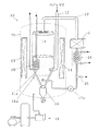
図1は実施の形態1のバイオマスのガス化装置の模式構成図である。
図1において、10は実施の形態1のガス化装置、11は木質片等のバイオマス粒及び流動媒体を保持して流動化させるための流動反応槽、11aは流動反応槽11の流動床部、12はホッパ(図示せず)からバイオマス粒を流動床部11aに連続的に供給するためのバイオマス供給管、13は略円筒状の流動反応槽11を囲繞して配置された流動床加熱部、14は流動床部11aの底部に設けられたバイオマス粒分解後の灰が排出される灰排出部、15は循環される生成ガスを脱塵処理するためのフィルタを備えた脱塵処理部、16は流動床部11aから取り出される生成ガスの熱を回収するための循環ガスの熱回収部、17は流動床部11a上部から生成ガスを取り出して脱塵処理部15、熱回収部16に送り流動床部11aの底部へ循環させるガス循環路、17aはガス循環路17に配設された送風機、18は流動床部11a内から熱を直接回収するための流動床熱回収部、19はガス化装置10の本体外殻部に酸化性ガス(空気)を供給し流動床部11a内に流動層を形成させるための空気等の酸化性ガスを供給する酸化性ガス供給部、19aは本体外殻部の酸化性ガスを流動床部11aに供給し流動化させる流動化ガス供給管、20は脱塵処理部15、熱回収部16、ガス循環路17、送風機17aを備えたガス循環調整部から生成ガスを製品ガスとして取り出すための製品ガス排出管、21は流動床部11a及び流動床加熱部13、灰排出部14等を内蔵し内部圧が0.1〜0.3パスカルに調整されたガス化装置10の本体外殻部である。
【0017】
流動媒体は、石灰石などに例えば0.1〜30%濃度の水酸化カリウム溶液を含浸処理して有機成分ガス化触媒を担持させて低温ガス化プロセスを実現するものであり、これによりタールやチャー成分の発生を抑制してこれらの処理に伴う排ガス処理設備を省略又は小容量化すると共にガス化効率の向上が図られる。
アルカリ金属塩、特にカリウム塩は石炭、チャー、炭素、黒鉛等のガス化反応において高い活性を示す。その触媒反応はアルカリ酸化物が炭素と錯体を形成し、COの脱離によりアルカリ金属への還元及び、気相中のアルカリ金属の酸化による還元酸化サイクルを繰り返すことにより進行するものとされている。
循環ガスの熱回収部16及び流動床熱回収部18は熱媒体となる水を供給して、生成ガスや流動層中のガスの熱で水を加熱して蒸気又は高温水として回収する熱交換器である。
流動床加熱部13は電気ヒータを備えた装置である。この流動床加熱部13及びガス循環調整部を、流動床部11a内の温度を測定する図示しないセンサから取得される温度データに基づいて、400〜600℃の所定温度に制御することができるようになっている。
【0018】
以上のように構成されたバイオマスのガス化装置10に適用されるバイオマスのガス化方法について説明する。
まず、所定量のカリウム分が担持された石灰石やドロマイト、マグネシアなどの流動媒体を流動床部11a内に供給し、酸化性ガス供給部19のコンプレッサやエアチャンバー、マスフローなどを介して酸化性ガスである空気を供給して流動化させる。次に、所定粒度に破砕したバイオマス粒をバイオマス供給管12を介して流動床部11aに供給して、バイオマス粒と流動媒体とで流動層を形成させる。流動床加熱部13等を介して加熱してバイオマス粒の部分酸化を進行させて分解ガス化を促すことができる。さらにバイオマス粒を所定供給量で連続的に供給しつつ、ガス化を進行させ、ガス循環調整部を介して循環ガスを流動反応槽11内に循環させる。こうして、ガス循環調整部から製品ガスを製品ガス排出管20を介して取り出して、流動床部11a内の温度が所定範囲になるように稼動状態を定常に維持させる。
【0019】
次に、流動層内の還元酸化プロセスにおける流動媒体の役割及び触媒作用について説明する。
図2はこのような流動層内の還元酸化プロセスにおける流動媒体の役割及び触媒作用を示す模式図である。
図示するように、木質片(wood)などのバイオマス粒を流動床中で流動媒と共に400〜600℃で流動化させる。こうして、カーボン(Cabon)等の粒子表面に付着したK、K2O、K2CO3を含むCaCO3/CaOと接触させ、この触媒作用によってガス化反応を促進させ、CO、H2、CH4、CO2等の分解ガスにして系外に排出させる。一方、残余のカリウム分や石灰分を含む灰を下部から排出して回収することができる。
なお、接触ガス化反応は図示するように、▲1▼C−CO2反応、▲2▼C−O2反応、▲3▼C−H2O反応の3プロセスを含み、これにより木質片、タール、チャーの分解ガス化を、カリウム分を担持し流動層中を浮遊するCaCO3/CaO粒子表面上で効果的に進行させることができる。
すなわち、図2に示すように、このような▲1▼〜▲3▼の反応プロセスでは、まず、K2CO3がK2OとCO2に分解する。次に、生成したK2Oなどが雰囲気中のCO2やO2、H2Oと間で相互に酸化還元を繰り返すリサイクル反応によりKを生成する。このKが再びO2やCO2で酸化されてK2OやK2CO3の触媒として流動媒体であるCaCO3/CaO粒子表面などに形成される。
従来の木材ガス化法では反応温度が1000℃付近と高いため、木材中に含まれるカリウム等のアルカリ分は金属に還元されて昇華し生成ガスと共に排出され、ガス化触媒として活用できないばかりでなく、その後のガス活用にも多くの制約があった。しかし、本実施の形態によるガス化方法では600℃以下の低温ガス化反応なので、生成ガス中のアルカリ金属濃度は大幅に低減され、流動媒体上に多く残留させてタール、チャー成分のガス化触媒としての機能を十分活用できることが明らかになった。
また、酸化カルシウム等の適当な担体を反応炉内に存在させる事によりアルカリ金属を完全に捕捉できるので、触媒の補充や入れ替えなしにガス化効率を高い水準で維持する事が可能となる。さらにメンテナンスの煩雑な生成ガス精製等の設備も簡便化できる小型ガス化システムに適していることも明らかになった。
【0020】
(実施例)
流動層内温度450℃、キャリヤーガス(酸化性ガス)におけるCO2/空気比=4/1でのバイオマス粒、及び木炭の重量減少よりカリウム塩の触媒効果を調べた結果、カリウム塩を添加することによってバイオマス粒においては熱分解後の残さ分のガス化速度を促進する事が確かめられた。特に、木炭のガス化においてはその差はより顕著に現れ、ガス化速度を大幅に促進することが明らかになった。
低温ガス化においては反応中タール、チャー等の重質炭化水素、木炭の生成が考えられ、これらのタール、チャーのガス化触媒として炭酸カリウムは有効な触媒であることがわかった。
流動層内温度550℃、CO2/O2比=1/1の条件での難ガス化物質である黒鉛のガス化実験においては、KOH触媒の添加によりガス化率が15%から85%に向上することが明らかになった。また、ペロブスカイト担持炭酸カリウム触媒は、流動層内温度450℃、4vol%程度の低酸素濃度の条件下での活性炭のガス化において、炭酸カリウムを炭素に含浸させた物と比較してガス転化率を2.3%から98%へと大幅に向上させる事がわかった。
ここでペロブスカイトの役割は、カリウム塩の還元活性化及び高効率捕捉に有り、反応後の触媒ロス量は炭素担持触媒の17%に対し、4%と大幅に低減できることが分かった。
低温での完全ガス化を達成するためには、生成するタール、チャー成分の高効率ガス化、高効率接触ガス化を可能とする触媒成分を用いることにより600℃以下の低温でガス化でき、カリウム触媒を用いた本ガス化手法はバイオマスから燃焼ガスを高効率に得る有効な手法であることが明らかになった。
【0021】
実施の形態1のバイオマスのガス化方法及びそのガス化装置は以上のように構成されているので、以下の作用を有する。
(a)有機成分ガス化触媒が担持された流動媒体とバイオマス粒からなる流動層が酸化性ガスにより形成される流動床部11aを有するので、低温下でもバイオマス粒のガス化反応を効率的に起させることができ、炭化水素の部分酸化反応を抑制して、生成ガス中のメタン含有量を確保し生成ガスの発熱量が低下するのを効果的に防止できる。
(b)有機成分ガス化触媒が担持された流動媒体中でバイオマス粒を分解ガス化させるので、不純物の少ない製品ガスが得られ、大規模なガス精製設備等を要せず、この製品ガスを燃料とする発電システム等を小型化できる。
(c)流動床部11aや循環ガスから低圧蒸気として熱回収し、工場プロセスの蒸気供給等のコジェネレーションシステムによる総合熱効率の向上が図れる。
(d)バイオマス生成ガスの一部を処理して循環させるので、流動層の流動化状態に応じて、循環ガス量を調整する制御性に優れており、バイオマス粒の分解ガス化条件を適切に維持させることができる。
(e)フィルタを備えた脱塵処理部15で生成ガスの脱塵処理を行うことで、バイオマス粒と流動媒体からなる流動層内を適正条件に維持でき、分解ガス化効率を高めた状態での稼動が容易にできる。
(f)循環ガス熱回収部16を備え、生成ガスの一部から熱回収できるので、熱ロスを少なくして経済性に優れている。
(g)流動反応槽11を囲繞して配置された流動床加熱部13を有するので、ガス化反応の行われる流動層内の温度制御性に優れ、常時所定のガス成分範囲に調整された生成ガスを効率的に製造できる。
(h)バイオマス粒中のアルカリ成分を流動層中で流動媒体に捕捉することができるので、ガス化炉における触媒効果を向上できるのみならず、アルカリ分の少ない生成ガスを供給でき、その取り扱いを容易にしてガスの生産性や作業性に優れている。
(i)アルカリ金属塩等のアルカリ分による接触ガス化反応を利用することができる。アルカリ金属塩、特にカリウム塩は石炭、チャー、炭素、黒鉛等のガス化反応において高い活性を示す。
(j)触媒を担持させた流動媒体を反応炉内に存在させる事によりアルカリ金属を完全に捕捉できるので、触媒の補充や入れ替えなしにガス化効率を高い水準で維持する事が可能となる。
(k)400〜600℃の低温でガス化処理がなされるので、バグフィルタ、メタルフィルタによる除塵が可能で、簡易な手法でタービンヘ送るガスを浄化できる。
(l)酸性ガスとして酸素を用いた場合には、メタノール合成用原料ガスの製造も可能であり、従来に比べ熱量収率を約15−35%も高めることができる。
(m)流動床ガス化法を適用しているので、固定床ガス化法によるものよりも均一な熱伝導が可能で低比重のバイオマス粒にも適用できる。
(n)流動媒体が炭酸カルシウム及び/又は酸化カルシウムを含む粒状体からなるので、処理中に発生する硫黄分や塩素化合物、ダイオキシン等の有害物を効果的に捕捉して、精製されたガスを得ることができる。
(o)有機成分ガス化触媒として活用した木材中のカリウム分は灰中に捕捉されるため、この灰を回収してカリウム肥料等として土壌に還元活用できる。
(p)木質のバイオマス粒のガス化反応触媒を、その高い活性を保持したまま流動反応装置用媒体(比重や粒径)に担持させることで、ガス化反応温度を低く設定できる。
(q)流動床部にガスを循環させるガス循環調整部と、流動床部の温度を調整する流動床加熱部とを連係させて作動させることにより、流動層における温度や流量等の流動条件を制御して、生成ガスの発生効率や熱効率を高め、効率的に運用することができる。
(r)本体外殻部21の内部圧を大気圧よりも高くして設定することもできるので、内部の空気を流動床に供給することにより熱効率を高めるとともに、装置のメンテナンス性やガス量等の制御性に優れている。
【0022】
(実施の形態2)
本発明の実施の形態2に係るバイオマスのガス化方法を適用するガス化装置について図面を参照しながら説明する。
図3は実施の形態2のバイオマスのガス化装置の模式構成図である。
図3において、30は実施の形態2のガス化装置、31は有機成分ガス化触媒が担持された流動媒体が保持されバイオマス粒が供給されて流動化させる流動反応槽31aの流動床部、32はバイオマス粒を貯留する外部ホッパ33に連設され内部圧が0.1〜0.3パスカルに調整された圧力容器34内でバイオマス粒を所定圧力で保持させるためのロックホッパ、35はロックホッパ32内のバイオマス粒を流動床部31に供給するためのバイオマス供給管、36は流動床部31を囲繞して加熱するための流動床加熱部、37は流動床部31の底部に設けられたバイオマス粒分解後の灰が排出される灰排出部、38は流動床部31の上部から取り出される排ガスが供給され排ガス中の未燃焼分の一部を回収して流動床部31に戻すと共に生成ガスをその天井中心側から排出するサイクロン、39はサイクロン38から取り出された生成ガスをろ過処理するためのバグフィルタ等を備えた脱塵処理部、40は供給される加圧空気と生成ガスとを混合燃焼させて燃焼ガスを発生させるためのコンバスタ(燃焼器)、41はコンバスタ40で加圧された燃焼ガスが供給されて駆動されるガスタービン41aとガスタービン41aの駆動軸を介して駆動され外部空気を取り込んで加圧して流動床部31の底部に供給するコンプレッサ41bとガスタービン41aにより駆動される発電機41cとを備えた発電装置、42はガスタービン41aから燃焼ガスを製品ガス等として取り出す燃焼ガス排出管、43は燃焼ガス排出管42に分岐して配置され、燃焼ガスの一部を流動床部31の底部に供給してバイオマス粒や流動媒体を流動化させるための循環ガス分岐管、44は必要に応じて配置され脱塵処理部39から排出される燃焼ガスの一部を取り出して流動床部31に還流させるための燃焼ガス調整管、45はコンプレッサ41bで圧縮された空気を流動床部31の底部(圧力容器34)に供給する圧縮空気供給管、46は圧縮空気供給管45から分岐して設けられ圧縮空気の一部をコンバスタ40に供給するための圧縮空気分岐管である。
【0023】
実施の形態2のバイオマスのガス化装置は、そのガス循環調整部のシステムの一部にガスタービン41a、コンプレッサ41b、発電機41cとを備えた発電装置41が組み込まれている点で実施の形態1のものと異なっている。
以上のように構成されたバイオマスのガス化装置30の稼動方法について説明する。まず、カリウム分が担持された石灰石からなる流動媒体を流動床部31内に供給する。次いで図示しない起動用のコンプレッサなどを介して酸化性ガスである空気を供給して流動化させる。次に、所定粒度に破砕したバイオマス粒を外部ホッパ33、ロックホッパ32を介して流動床部31に供給して、バイオマス粒と流動媒体とで流動層を形成させる。
このとき流動床加熱部36等を介して流動層が形成される流動床部31内を加熱してバイオマス粒の部分酸化を進行させ、バイオマス粒を所定供給量で連続的に供給して、燃焼ガス調整管44や循環ガス分岐管43等で流量や圧力、酸素濃度等が調整されたガスを流動床部31内に循環させる。こうして、コンバスタ40で未燃焼分のメタンや一酸化炭素、二酸化炭素等含むガスを燃焼ガス排出管42から製品ガスとして取り出すこともできる。また、流動床部31内の温度が所定範囲になるように稼動状態を定常に維持させることもできる。一方、サイクロン38を介して排出される燃焼ガスはコンバスタ40で加熱圧縮された燃焼ガスの一部を含む予熱空気と混合燃焼されて、ガスタービン41aを駆動させる。
これによって発電機41cとコンプレッサ41bの駆動軸を動かして、外部空気の取り込みと、所定の電力供給とを同時に効率的に行うことができる。
なお、実施例1の場合と同様に流動床部31内から熱を直接回収するための図示しないコイル状等に形成された熱交換器からなる流動床熱回収部を設けることによって、流動床部31内で発生する燃焼熱を回収したり、流動層内を所定の温度に維持させたりすることもできる。
【0024】
実施の形態2のバイオマスのガス化方法は以上のように構成されているので、実施の形態1の作用に加えて、以下の作用を有する。
(a)流動床部31内の流動媒体に有機成分ガス化触媒が担持されて所定濃度の燃焼ガスが得られると共に、この燃焼ガスを駆動源とするガスタービン41aとコンプレッサ41bとが一体化して構成された発電装置41を有するので、全体を小型化することができ比較的小規模な発電システムを構築できる。
(b)燃焼ガス調整管44を用いて脱塵処理部39から取り出される燃焼ガスの一部をコンバスタ40を経由させることなく流動床部31に戻して酸素ガス濃度の調整を行うことができ、ガス化装置30の制御性に優れている。すなわち、脱塵処理部からの燃焼ガスにおける酸素濃度はコンバスタ40から排出されるガスよりも低いため、炉内の酸素濃度を確実に低減させることができ、これによって、流動床部31に供給するガス中の酸素ガス濃度を効果的に調整できる。
【0025】
【発明の効果】
請求項1に記載のバイオマスのガス化方法によれば、以下の効果を有する。
(a)有機成分に対するガス化触媒(有機成分ガス化触媒)が担持された流動媒体上でバイオマス粒をガス化させるので、不純物の少ない生成ガスが得られ、大規模なガス精製設備を要せず、この生成ガスを燃料とする発電システム等を小型化することができる。
(b)比較的低温下でバイオマス粒のガス化反応をおこさせるので、炭化水素の部分酸化反応が進行してCO含有量が大幅に多くなるようなことがなく、生成ガス中のメタン含有量を確保して生成ガスの発熱量が低下するのを防止できる。
(c)バイオマス粒中のアルカリ成分が流動層中で流動媒体に捕捉されるので、アルカリ分の少ない生成ガスを供給でき、その取り扱いを容易にし生産性に優れている。
(d)低温でガス化処理がなされるので、バグフィルタ、メタルフィルタによる除塵が可能で、簡易な手法でタービンヘ送るガスを浄化できる。
(e)バイオマス粒を燃料として有効利用でき、かつ高カロリーガスを製造できるため、メタネーションが支配的な低温での低圧流動床低温接触ガス化技術を小型システムとして構成することができる。
(f)この流動化のための酸性ガスとして空気の代りに酸素を添加した場合には、メタノール合成用原料ガスの製造も可能であり、従来のものに比べ熱量収率を約15−35%も高めることができる。
(g)ガス発生効率に優れるため最小ユニット規模が1.5t/日程度の小型でコンパクトなガス化装置を実現でき、工場毎に分散したバイオマス資源を有効に活用してガス化装置とガスタービンあるいは燃料電池等によるコジェネレーションシステムとして適用でき、エネルギー有効活用性に優れている。
(h)流動床ガス化法を適用しているので、固定床ガス化法によるものよりも均一な熱伝導が可能で低比重のバイオマス粒にも適用でき、また、タール、オイル分の生成が少ない等の利点を有する。
(i)処理中に生成するSOx、NOx、ダイオキシン、環境ホルモン等を含む有害ガスを流動媒体に捕捉して除去することもできるので、環境保護性にも優れている。
(j)鉱物の含有量がわずかであり、かつカリウムが主要成分であるバイオマスを選択することによって、バイオマス粒中のアルカリ成分をガス化触媒として失活させることなく、有効に活用して不純物が少なく高カロリーのガスを生成することができる。
【0026】
請求項2に記載のバイオマスのガス化方法によれば、請求項1に記載の効果に加えて以下の効果を有する。
(a)アルカリ金属塩等のアルカリ分による接触ガス化反応を利用することができる。アルカリ金属塩、特にカリウム塩は石炭、チャー、炭素、黒鉛等のガス化反応において高い活性を示す。すなわち、アルカリ酸化物が炭素と錯体を形成し、COの脱離によりアルカリ金属へ還元され、気相中の酸素により酸化されるアルカリ金属−アルカリ金属酸化物の酸化還元サイクルを繰り返すことにより触媒反応を効果的に進行させることができる。
(b)従来の高温ガス化法では生成ガス中に含まれて散逸していた木質系バイオマス粒中のカリウム分を、炭酸カルシウムや酸化カルシウムからなる流動媒体と反応させることにより効率よく吸着、捕捉でき、有機成分ガス化触媒として再利用ができる。
(c)触媒を担持させた流動媒体を反応炉内に存在させることによりアルカリ金属を完全に捕捉できるので、触媒の補充や入れ替えなしにガス化効率を高い水準で維持する事が可能となる。
(d)木材中のカリウム分は流動媒体粒子に吸着捕捉されるので、これを回収してカリウム肥料等として土壌に還元活用できる。
(e)木材中の塩素化合物はカルシウム化合物に塩化カルシウムとして捕捉されるので、ダイオキシンが発生するのを防止できる。またバイオマス粒の処理中に環境ホルモンを含むガスが発生してもこれを流動媒体に吸着させて除去することもできる。
(f)流動媒体が炭酸カルシウム及び/又は酸化カルシウムを含む粒状体からなるので、処理中に発生する硫黄分やダイオキシン等の有害物を効果的に捕捉して、精製された生成ガスを得ることができる。
(g)木質のバイオマス粒のガス化反応触媒を、その高い活性を保持したまま所定の比重や粒径の流動反応装置用媒体に担持させることで、ガス化反応温度を低く設定でき、省エネルギー性に優れると共に、生成ガス中のメタンをより高濃度に製造し、発生ガスの高発熱量化を図ることができる。
(h)タール、チャー等の分解を促進させる有機成分ガス化触媒として、木材中のアルカリ成分であるカリウムを有効に活用できる。
(i)反応段数を多くできる流動反応装置と組み合せることで装置自体の小型化、コンパクト化が可能となる。
【0027】
請求項3に記載のバイオマスのガス化方法によれば、請求項2の効果に加えて以下の効果を有する。
(a)バイオマス粒中に含まれるカリウム分を、炭酸カルシウムや酸化カルシウム等の流動媒体により効率よく捕捉して、このカリウムが担持された流動媒体を有機成分ガス化触媒として有効に利用できる。
(b)従来の高温ガス化法では生成ガス中に揮発して利用できなかったカリウム分を回収することができる。
【0028】
請求項4に記載のバイオマスのガス化方法によれば、請求項3の効果に加えて以下の効果を有する。
(a)流動層が形成される流動床部の底部に設けられた灰排出部から排出される高温のカリウム含有灰などを急冷してガラス化を促進させることもでき、これによって、カリウム等のアルカリ分を灰中のガラス分に安定に保持させることができ、カリウム等のアルカリ分の保持性に優れた肥料を提供できる。
(b)ガス化装置をカリウム肥料等のアルカリ含有肥料の製造装置として利用することができ、システムとしての生産性に優れている。
(c)バイオマス粒をガス化させるのと同時にカリウム肥料等のアルカリ含有肥料の製造ができるので、エネルギー及び資源の有効活用が図られる。
【0029】
請求項5に記載のバイオマスのガス化方法によれば、請求項1の効果に加えて以下の効果を有する。
(a)バイオマス粒のガス化の際に発生する有害ガスが流動媒体で捕捉されるので、有害ガスの放出や漏洩等による周囲の環境への影響が抑制され、環境保護性に優れている。
(b)バイオマス粒のガス化の際に有害ガスが除かれるので、以降のガス処理工程での処理が容易になり、全体の処理コストを低減でき経済性に優れている。
【0030】
請求項6に記載のバイオマスのガス化方法によれば、請求項1乃至5の内いずれか1項に記載の効果に加えて以下の効果を有する。
(a)流動層中におけるバイオマス粒と流動媒体の質量比が特定範囲に設定されているので、木質片などからなるバイオマス粒を流動層中で均一かつ効果的に撹拌させることができる。
(b)流動化状態が適切に維持されるので、炭化水素の部分酸化反応の制御を容易にして、CO生成の低減による低分子量炭化水素生成量を向上させ生成ガス発熱量の向上を図ることができる。
【0031】
請求項7に記載のバイオマスのガス化方法によれば、請求項1乃至6の内いずれか1項の効果に加えて以下の効果を有する。
(a)生成ガスの一部を処理して循環させるガス循環調整工程を有するので、流動層の流動化状態に応じて、循環ガス量を調整する制御性に優れており、常時、バイオマスの分解ガス化条件を適切に維持させ、タールやチャー等の不純物の少ない精製ガスを多量に製造でき生産性に優れている。
(b)流動層からバイオマスをガス化したガスの一部を取り出して脱塵処理を行ってこれを流動層に循環供給させることができ、バイオマス粒と流動媒体からなる流動層内を適正条件に維持でき、分解ガス化効率を高めた状態での稼動が容易にできる。
(c)生成ガスの一部から熱回収できるので、熱ロスを少なくして経済性に優れている。
【0032】
請求項8に記載のバイオマスのガス化装置によれば、以下の効果を有する。
(a)バイオマスのガス化装置が、有機成分ガス化触媒が担持された流動媒体とバイオマス粒からなる流動層が酸化性ガスにより形成される流動床部を有するので、低温下でもバイオマスのガス化反応をおこさせることができ、炭化水素の部分酸化反応を抑制して、生成ガス中のメタン含有量を確保し生成ガスの発熱量が低下するのを効果的に防止できる。
(b)バイオマスのガス化により得られた燃料ガスを小型発電機に適用して発電すると共に、流動床部の循環ガスや発電機の排ガスを低圧蒸気として熱回収することができるので、乾燥熱源、工場プロセス蒸気供給等のコジェネレーションシステムによる総合熱効率の向上が図れる。
(c)バイオマス粒中のアルカリ成分を流動層中で流動媒体に捕捉して、アルカリ分の少ない生成ガスを供給でき、その取り扱いを容易にし生産性や作業性に優れている。
(d)流動床部を囲繞して配置された流動床加熱部を有するので、ガス化反応の行われる流動層内の温度を制御する制御性と熱利用効率性に優れ、常時所定のガス成分範囲に調整された生成ガスを効率的に製造できる。
(e)生成ガスの熱回収を行う熱回収部や生成ガス中の固体粒子をバグフィルタやセラミックフィルタ等のフィルタを用いて除去する脱塵処理部を有するので、装置系の熱効率を向上させたり、排出ガス中の脱塵を行うことで環境保護性を高めたりすることができる。
(f)流動床部にガスを循環させるガス循環調整部と、流動床部の温度を調整する流動床加熱部とを連係させて作動させることにより、流動層における温度や流量等の流動条件を制御して、生成ガスの発生効率や熱効率を高め、効率的に運用することができる。
(g)バイオマス粒を燃料として高カロリーでタール、チャー等の少ないガスを製造できるため、以降の排ガス処理を容易にできガス精製設備を省略又は小型化でき、小型システムとして構成することができる。
【図面の簡単な説明】
【図1】実施の形態1のバイオマスのガス化装置の模式構成図
【図2】流動媒体の役割及び触媒作用を示す模式図
【図3】実施の形態2のバイオマスのガス化装置の模式構成図
【符号の説明】
10 実施の形態1のガス化装置
11 流動反応槽
11a 流動床部
12 バイオマス供給管
13 流動床加熱部
14 灰排出部
15 脱塵処理部
16 熱回収部
17 ガス循環路
17a 送風機
18 流動床熱回収部
19 酸化性ガス供給部
19a 流動化ガス供給管
20 製品ガス排出管
21 本体外殻部
30 実施の形態2のガス化装置
31 流動床部
32 ロックホッパ
33 外部ホッパ
34 圧力容器
35 バイオマス供給管
36 流動床加熱部
37 灰排出部
38 サイクロン
39 脱塵処理部
40 コンバスタ(燃焼器)
41 発電装置
41a ガスタービン
41b コンプレッサ
41c 発電機
42 燃焼ガス排出管
43 循環ガス分岐管
44 燃焼ガス調整管
45 圧縮空気供給管
46 圧縮空気分岐管[0001]
TECHNICAL FIELD OF THE INVENTION
The present invention relates to forest waste (wood fragments such as sawdust, wood powder, thinned wood, etc.) and agricultural waste (rice husk, rice straw, surplus products, etc.) generated in the manufacturing process of furniture and woodwork products. Biomass resources such as sewage and wastewater (contaminants, manure residue, sewage sludge, etc.) and low-grade coal are gasified at relatively low temperatures into hydrocarbons, hydrogen, CO, etc., and energy for cogeneration systems for power generation, etc. The present invention relates to a biomass gasification method and a gasification apparatus that can be provided as a source or a raw material gas of an organic synthetic product such as for fertilizer.
[0002]
[Prior art]
Techniques for converting biomass resources into energy and raw material gas include methods such as ethanol fermentation, methane fermentation, and heat gasification.The disadvantage of fermentation is that conversion takes time and practical operation is difficult. is there.
As the heating gasification technology applicable to biomass, coal gasification technology is basically followed, and from the shape of the gasification reactor, the following (1) fixed bed gasification method, (2) spouted bed gas And (3) fluidized bed gasification.
(1) Fixed bed gasification method
A fire bed (fire ladder) etc. for forming a fixed bed at the bottom of the furnace is provided, and enzymes and the like are charged and the biomass on the fixed bed is heated and gasified in a high-temperature atmosphere, and the ash discharged downward is discharged. It is a device designed to take out slugs, and there are the Torrax process and PUROX process developed in the United States for the purpose of gasifying municipal solid waste.
(2) Spouted bed gasification method
Pulverized coal or the like is pressurized by a dry pressurized feeder and gasified by spraying with oxygen and water vapor by a burner installed in the lower part of the furnace. Is being done.
(3) Fluidized bed gasification method
The fluidized bed is formed by gas supplied from the furnace bottom, and gasification is performed in the fluidized bed. A two-column fluidized bed gasifier (BCL) operating at a power plant in Burlington in the United States has a structure in which two circulating fluidized bed furnaces, a combustion tower and a gasification tower, are connected via a cyclone. This is an improved process so that sand as a fluid medium can be moved between two furnaces. In this process, air is introduced into one side, complete combustion of char and the like, and heating of the fluidized medium, and steam is introduced into the other side to gasify biomass. Since this process uses an indirect heating method, the calorific value (17.8 MJ / Nm) is about half that of natural gas than wood chips. 3 ) Is possible, and gas turbine power generation is performed using this high calorific value gas.
As related to this fluidized bed gasification system, for example, Patent Document 1 discloses that a part of a substance containing carbon is partially oxidized by a gas containing oxygen in a fluidized bed, and most of the substance containing carbon is gasified. Gasification with an agent such as water vapor, hydrogen, carbon monoxide or a mixed gas thereof and adding quicklime, and the partial pressure of carbon dioxide in the product gas in the fluidized bed is calculated from the partial pressure of decomposition of calcium carbonate at that temperature. A method of pyrolyzing or gasifying a substance containing carbon, which reacts quicklime with carbon dioxide while maintaining the pressure at a high level, is described.
Patent Document 2 discloses a reactor that gasifies biomass fuel to generate product gas, a combustion furnace that burns unburned components extracted together with a fluidized medium from the reactor and heats the fluidized medium with a fluidized bed. A gas-solid separator that separates and collects the heated fluid medium extracted together with the combustion exhaust gas from the furnace top of the combustion furnace and supplies the collected fluid medium to the reactor. A gasifier for biomass fuel gasification combined cycle power generation in which a boiler that uses combustion exhaust gas as a heat source is integrally provided and an auxiliary fuel supply unit that supplies auxiliary fuel to a fluidized bed portion of the combustion furnace is described. .
[0003]
[Patent Document 1]
JP-B-57-5840
[Patent Document 2]
JP-A-63-140805
[0004]
[Problems to be solved by the invention]
However, the above conventional technology has the following problems.
(1) In the fixed bed gasification method of gasifying biomass in a fixed bed, it can be effectively used only for biomass having a large specific gravity, and a gas containing a relatively large amount of tar and oil is generated, thereby decomposing the biomass. There was a problem that it became worse.
(2) In the spouted bed gasification method in which finely divided biomass is blown into a furnace, there is a problem that it is difficult to process a large amount of biomass having a low density and the productivity of gas generation is poor.
(3) The gasification method described in Patent Document 1 requires steam, hydrogen, carbon monoxide, and the like separately as a gasifying agent, and also requires that the partial pressure of carbon dioxide in the fluidized bed be maintained at a predetermined pressure or higher. Since the activity of quicklime itself cannot be sufficiently exerted, there has been a problem that operation is difficult in a small-scale power generation facility or the like.
(4) According to the fluidized-bed gasification method described in Patent Document 2, biomass is uniformly gasified in a fluidized bed to enable large-scale treatment. However, alkali components derived from biomass are contained in generated gas. Gas purification equipment, making it difficult to reduce the size of equipment and systems, and the versatility when applied to fuel gas generators such as small-scale power generation systems attached to woodworking plants. There was a problem that lacked.
(5) In the conventional gasification technology in which the temperature is as high as 800 ° C. to 1000 ° C., the partial oxidation reaction of hydrocarbon proceeds to CO and the amount of methane produced is reduced, so that the calorific value is reduced and contains an alkali component. There was a problem that handling of gas became difficult.
(6) Since the gasification reaction is at a high temperature, there are many restrictions on equipment such as heat resistance, and the heat recovery during the treatment is not appropriate, resulting in a low calorific value yield and a lack of economy.
(7) There is a problem that harmful substances such as SOx, NOx, dioxin, and environmental hormones are generated and cannot be treated efficiently.
(8) Although it is known that an alkali component serves as a gasification catalyst, it has a drawback that it deactivates a substrate containing a large amount of minerals such as coal.
[0005]
The present invention has been made in order to solve the above-mentioned problems, and it is possible to treat a large amount of biomass having a relatively small specific gravity, and to perform a gasification reaction at a relatively low temperature without deterioration of the catalytic function even in the presence of coal. It provides a high-calorie gas production method and a biomass gasification method that excels in the removal of harmful gases, and has a high performance with a low generation rate of alkali, tar, and oil in the generated gas. An object of the present invention is to provide a compact and highly versatile biomass gasification apparatus that does not require a gas purification facility, is easily miniaturized, and can be easily applied to a small-scale power generation system and the like.
[0006]
[Means for Solving the Problems]
The biomass gasification method according to claim 1, wherein the biomass particles such as wood pieces and wood powder and a fluid medium supporting an organic component gasification catalyst are fluidized with an oxidizing gas to form a fluidized bed, The fluidized bed is maintained at a temperature of 400 to 600 ° C. to gasify the biomass particles.
This configuration has the following operation.
(A) Since biomass particles are gasified on a fluidized medium carrying a gasification catalyst for an organic component (organic component gasification catalyst), a product gas with few impurities can be obtained, and a large-scale gas purification facility is required. Instead, it is possible to reduce the size of a power generation system or the like using the generated gas as fuel.
(B) Since the gasification reaction of the biomass particles is caused at a relatively low temperature, the partial oxidation reaction of the hydrocarbon does not proceed, so that the CO content does not increase significantly, and the methane content in the product gas does not increase. To ensure that the calorific value of the generated gas does not decrease.
(C) Since the alkali component in the biomass particles is trapped in the fluidized medium in the fluidized bed, it is possible to supply a product gas containing a small amount of alkali, to facilitate the handling and to improve the productivity.
(D) Since gasification is performed at a low temperature of 400 to 600 ° C., dust can be removed by a bag filter or a metal filter, and gas sent to the turbine can be purified by a simple method.
(E) Since biomass particles can be effectively used as fuel and a high calorie gas can be produced, the low-temperature fluidized-bed low-temperature catalytic gasification technology at a low temperature where methanation is dominant can be configured as a small system.
(F) When oxygen is added instead of air as an acid gas for this fluidization, a raw material gas for methanol synthesis can be produced, and the calorific yield is about 15-35% as compared with the conventional one. Can also be increased.
(G) Since the gas generation efficiency is excellent, a small and compact gasifier with a minimum unit size of about 1.5 t / day can be realized, and the gasifier and the gas turbine can be effectively utilized by utilizing the biomass resources dispersed in each factory. Alternatively, it can be applied as a cogeneration system using a fuel cell or the like, and is excellent in effective energy utilization.
(H) Since the fluidized-bed gasification method is applied, more uniform heat conduction than that by the fixed-bed gasification method is possible, and it can be applied to biomass particles having a low specific gravity. It has advantages such as less.
(I) Since harmful gases including SOx, NOx, dioxin, environmental hormones and the like generated during the treatment can be captured and removed by the fluid medium, they are excellent in environmental protection.
(J) By selecting biomass having a small content of mineral components such as coal and potassium as a main component, the alkali components in the biomass particles can be effectively utilized without being deactivated as a gasification catalyst. Therefore, high calorie gas can be generated with less impurities.
[0007]
Here, biomass grains are forest waste generated during the manufacturing process of furniture and woodwork products (wood fragments such as sawdust, wood powder, thinned wood, etc.), and agricultural waste (rice husk, rice straw, surplus products). Etc.), water and sewage waste (contaminants, manure residue, sewage sludge, etc.), low-grade coal, and the like.
The temperature of the fluidized bed for gasifying the biomass particles is desirably maintained at 400 to 600C, preferably 450 to 550C. This depends on the type and form of the biomass particles to be treated, the amount supplied per hour to be supplied to the fluidized bed apparatus, but as the temperature of the fluidized bed becomes lower than 450 ° C, the decomposition efficiency decreases extremely. As a result, unburned components such as tar and char increase and the productivity tends to decrease. Conversely, as the temperature exceeds 600 ° C., the partial oxidation reaction proceeds to increase the content of CO gas and decrease the calorific value. This is because a tendency appears, and these tendencies become lower when the temperature is lower than 400 ° C. or more than 600 ° C.
Examples of the gasifier equipped with a fluidized bed include: (1) an HTW process in which a bubbling-type fluidized bed in which potassium is not volatilized and a high pressure and high temperature are achieved in a conventional winkle furnace; and (2) a pressurized fluidized bed. The same or similar to the KRW process or the like in which a high-temperature portion is formed at an air charging portion of a fluidized-bed hearth portion and ash is locally burned and melted to achieve ash fusion / aggregation can be applied.
As the oxidizing gas, in addition to air, oxygen gas, air in which the content of oxygen gas is adjusted, high-temperature steam, or a mixed gas thereof can be used.
As the fluid medium, limestone, sand, or a mixture thereof can be applied.For example, an organic component gasification catalyst such as potassium is supported on the fluid medium by a method such as immersing particles of the fluid medium in a solution containing potassium. Can be used.
It is desirable that the particle size of the fluid medium is in the range of 0.5 to 50 mm, preferably 1 to 20 mm. This depends on the fluidization conditions, but as the particle size becomes smaller than 1 mm, the fluidity of the wood particles to form a fluidized bed tends to be poor, and as the particle size exceeds 20 mm, the biomass particles become more effective. This is because there is a tendency that the effective surface area required for causing a catalytic reaction by contacting with water decreases, and these tendencies become smaller when the thickness is smaller than 0.5 mm or larger than 50 mm.
[0008]
In the method for gasifying biomass according to claim 2, in the invention according to claim 1, the fluidized medium is a granular material containing calcium carbonate and / or calcium oxide, and the organic component gasification catalyst is potassium or the like. It is constituted so that it may be alkali content of.
With this configuration, the following operation is obtained in addition to the operation described in the first aspect.
(A) A contact gasification reaction by an alkali component such as an alkali metal salt can be used. Alkali metal salts, especially potassium salts, show high activity in gasification reactions of coal, char, carbon, graphite and the like. That is, the alkali oxide forms a complex with carbon, is reduced to an alkali metal by elimination of CO, and is catalyzed by repeating a redox cycle of an alkali metal-alkali metal oxide oxidized by oxygen in a gas phase. Can be effectively advanced.
(B) The potassium content in the woody biomass particles contained in the generated gas and dissipated in the conventional high-temperature gasification method is reduced by a fluid medium composed of calcium carbonate or calcium oxide at an operating temperature of 500 to 600 ° C. It can be efficiently adsorbed and captured, and can be reused as an organic component gasification catalyst.
(C) Since the alkali metal can be completely captured by allowing the fluid medium supporting the catalyst to be present in the reaction furnace, the gasification efficiency can be maintained at a high level without replenishing or replacing the catalyst.
(D) Since the potassium content in the wood is adsorbed and captured by the fluid medium particles, the potassium content can be recovered and reused in the soil as potassium fertilizer or the like.
(E) Since the chlorine compound in the wood is captured as calcium chloride by the calcium compound, generation of dioxin can be prevented. In addition, even if a gas containing an environmental hormone is generated during the processing of the biomass particles, the gas can be removed by adsorbing the gas on the fluid medium.
(F) Since the fluidized medium is a granular material containing calcium carbonate and / or calcium oxide, it is possible to effectively capture harmful substances such as sulfur and dioxin generated during the treatment and obtain a purified product gas. Can be.
(G) The gasification reaction temperature can be set low by supporting the gasification reaction catalyst of woody biomass particles on a medium for a fluidized reaction device having a predetermined specific gravity and particle size while maintaining its high activity, thereby saving energy. Methane in the product gas can be produced at a higher concentration, and the calorific value of the generated gas can be increased.
(H) Potassium, which is an alkali component in wood, can be effectively used as an organic component gasification catalyst that promotes the decomposition of tar, char, and the like.
(I) Combination with a flow reactor capable of increasing the number of reaction stages makes it possible to reduce the size and size of the device itself.
[0009]
Here, the alkali content in the fluid medium is desirably in the range of 0.05 to 10% by mass, preferably 1 to 5% by mass. This depends on the form and type of the biomass particles to be treated, but as the alkali content acting as the organic component gasification catalyst becomes less than 1% by mass, the harmful substance trapping efficiency and the decomposition gasification efficiency decrease. On the contrary, as the content exceeds 5% by mass, there is a tendency that alkalis are released into the product gas to cause adverse effects such as the necessity of gas purification treatment, and these tendencies become less than 0.05% by mass. , Or more than 10% by mass.
[0010]
The method for gasifying biomass according to claim 3 is the method according to claim 2, wherein the biomass particles are heated in a fluidized state in the fluidized bed to remove alkali components such as potassium contained in the biomass particles. It is configured to be volatilized and loaded on the fluid medium.
This configuration has the following operation in addition to the operation of the second aspect.
(A) Potassium contained in biomass particles is efficiently captured by a fluid medium such as calcium carbonate or calcium oxide, and the fluid medium carrying potassium can be effectively used as an organic component gasification catalyst.
(B) Potassium, which was volatilized and dissipated in the generated gas and could not be used in the conventional high-temperature gasification method, can be effectively recovered.
Here, potassium hydroxide, potassium carbonate, or the like can be used as a potassium source that is an alkali component.
[0011]
The method for gasifying biomass according to claim 4 is the invention according to claim 3, wherein the fluidized medium taken out from the bottom of the fluidized bed is cooled to become an alkali-containing fertilizer such as a potassium fertilizer. Have been.
This configuration has the following operation in addition to the operation of the third aspect.
(A) High-temperature potassium-containing ash discharged from an ash discharge unit provided at the bottom of a fluidized bed in which a fluidized bed is formed can be rapidly cooled to promote vitrification. The alkali content can be stably retained by the glass content in the ash, and a fertilizer excellent in retention of the alkali content such as potassium can be provided.
(B) The gasifier can be used as a device for producing an alkali-containing fertilizer such as a potassium fertilizer, and is excellent in productivity as a system.
(C) Alkaline-containing fertilizers such as potassium fertilizers can be produced at the same time as gasification of biomass particles, so that energy and resources can be effectively used.
[0012]
According to a fifth aspect of the present invention, there is provided the biomass gasification method according to the first aspect of the present invention, wherein the harmful gas containing chlorides such as SOx, NOx, dioxin and the like, and organic substances such as environmental hormones generated in the fluidized bed is used as the fluid medium To be adsorbed and trapped in a fluid stirring state.
This configuration has the following operation in addition to the operation of the first aspect.
(A) Since the harmful gas generated during the gasification of the biomass particles is trapped on the surface of or inside the particles of the flowing medium in which the harmful gas flows and diffuses, the influence on the surrounding environment due to the release or leakage of the harmful gas is suppressed. Excellent in environmental protection.
(B) Since the harmful gas is removed when the biomass particles are gasified, the treatment in the subsequent gas treatment step is facilitated, and the overall treatment cost can be reduced and the economy is excellent.
Here, in order to efficiently capture the harmful gas in the fluid medium, it is preferable that the oxygen concentration in the atmosphere gas be in the range of 0 to 20%, preferably 5 to 10% in the fluid combustion state. This depends on the type of harmful gas adsorbed on the fluid medium and the particle size and surface area of the fluid medium, but as the oxygen concentration becomes lower than 5%, the gasification by oxidation or decomposition of biomass tends to be insufficient. This is because, as it becomes higher than 10%, the calorific value of the generated gas tends to decrease, and when it becomes more than 20%, it becomes more remarkable.
Further, the pressure of the atmospheric gas is preferably in the range of 0.01 to 1.0 Pascal, preferably 0.1 to 0.3 Pascal. This depends on the type of generated gas, combustion temperature, oxygen concentration, etc., but as the pressure becomes lower than 0.1 Pascal, the trapping efficiency in the fluid medium tends to decrease, and conversely, from 0.3 Pascal. This is because the higher the pressure, the more difficult it becomes to inject gas to form a fluidized bed, and these tend to be more remarkable when the pressure is lower than 0.01 Pascal or higher than 1.0 Pascal.
[0013]
The method for gasifying biomass according to claim 6 is the method according to any one of claims 1 to 5, wherein the biomass particles (A) and the fluid medium (B) loaded on the fluidized bed are provided. Is configured so that the mass ratio (A / B) to the above is 1/100 to 1/2.
With this configuration, the following operation is provided in addition to the operation described in any one of the first to fifth aspects.
(A) Since the mass ratio between the biomass particles and the fluidized medium in the fluidized bed is set in a specific range, the biomass particles composed of wood pieces and the like can be uniformly and effectively stirred in the fluidized bed.
(B) Since the fluidized state is appropriately maintained, the control of the partial oxidation reaction of hydrocarbons is facilitated, and the amount of low molecular weight hydrocarbons generated by reducing CO generation is improved, and the calorific value of generated gas is improved. Can be.
Here, the mass ratio (A / B) between the biomass particles and the fluid medium supplied to the fluidized bed is preferably in the range of 1/100 to 1/2, preferably 1/50 to 1/10.
This depends on the form of the biomass granules, but as the mass ratio (A / B) becomes smaller than 1/50, the treatment efficiency of the biomass granules tends to be extremely reduced. The gasification efficiency tends to decrease because the fluidized state of the biomass particles becomes non-uniform, and these tendencies occur when the mass ratio (A / B) becomes smaller than 1/100 or exceeds 1/2. This is because it becomes more noticeable.
[0014]
According to a seventh aspect of the present invention, in the method for gasifying biomass according to any one of the first to sixth aspects, a part of the gas obtained by gasifying the biomass particles is extracted from the fluidized bed to recover heat. After the treatment and / or the dust removal treatment, a gas circulation adjustment step of circulating the fluidized bed is provided.
With this configuration, the following operation is provided in addition to the operation of any one of the first to sixth aspects.
(A) Since it has a gas circulation adjusting step of processing and circulating a part of the product gas in which the biomass particles are decomposed, the controllability of adjusting the amount of circulating gas according to the fluidized state of the fluidized bed is excellent. In addition, the gasification conditions of the biomass particles are constantly maintained appropriately, and a large amount of purified gas containing less impurities such as tar and char can be produced, and the productivity is excellent.
(B) A part of the gas obtained by gasifying the biomass particles from the fluidized bed can be taken out, subjected to a dust removal treatment, and circulated and supplied to the fluidized bed. , And can be easily operated with enhanced gasification efficiency.
(C) Since heat can be recovered from a part of the generated gas, heat loss is reduced and the economy is excellent.
Here, the ratio (C / D) of the circulating gas amount (C) circulated through the fluidized bed to the total gas amount (D) discharged from the fluidized bed is 1/10 to 1/2, preferably 1 /. It is desirable to set the range of 5 to 1/3. This depends on the application conditions such as the temperature and volume of the fluidized bed, the amount of biomass particles processed, and the amount of fluidized medium supplied, but as the amount of circulating gas becomes smaller than 1/5 of the total amount of exhaust gas, the heat recovery efficiency and The dust removal efficiency tends to decrease and the operating state tends to deteriorate. As the ratio exceeds 1/3, the capacity of the air supply system such as a pump and a fan for circulating the circulating gas becomes excessive and the workability deteriorates. This is because tendencies appear, and these tendencies become smaller than 1/10 or become more pronounced when they exceed 1/2.
[0015]
In the biomass gasifier according to claim 8, the biomass particles such as wood pieces and wood powder are supplied from the body wall of the biomass via a biomass supply pipe, and the carbon dioxide is loaded with an organic component gasification catalyst such as potassium. A fluidized bed section that holds a fluidized medium such as calcium or calcium oxide and forms a fluidized bed composed of the biomass particles and the fluidized medium by an oxidizing gas supplied through a fluidizing gas supply pipe provided at the bottom thereof. And a fluidized bed heating section disposed surrounding the fluidized reaction vessel, and an ash discharge section provided at the bottom of the fluidized bed section for discharging the ash after the biomass particle decomposition is provided. A heat recovery unit and / or a dust removal unit that performs heat recovery and / or dust removal of a product gas obtained by decomposing the biomass particles discharged from an upper portion of the fluidized bed unit; and a product gas that is subjected to heat recovery and dust removal. The fluidized bed section It is configured by a gas circulation adjuster for circulating the bottom.
This configuration has the following operation.
(A) Since the biomass gasifier has a fluidized bed formed by an oxidizing gas, a fluidized bed composed of a biomass particle and a fluidized medium carrying an organic component gasification catalyst, the gas of the biomass particle can be produced even at a low temperature. It is possible to suppress the partial oxidation reaction of hydrocarbons, secure the methane content in the product gas, and effectively prevent the calorific value of the product gas from decreasing.
(B) Since the fuel gas obtained by gasification of the biomass particles is applied to a small generator to generate electric power, the circulating gas in the fluidized bed and the exhaust gas from the generator can be heat-recovered as low-pressure steam. Improve overall thermal efficiency with cogeneration systems such as heat sources and factory process steam supply.
(C) The alkali component in the biomass particles is captured in the fluidized medium in the fluidized bed, and a product gas with a small amount of alkali can be supplied, the handling thereof is facilitated, and the productivity and workability are excellent.
(D) Since it has a fluidized bed heating section disposed around the fluidized bed section, it has excellent controllability for controlling the temperature in the fluidized bed in which the gasification reaction is performed and heat utilization efficiency, and always has a predetermined gas component. The product gas adjusted to the range can be efficiently produced.
(E) Since it has a heat recovery unit that recovers heat of the generated gas and a dust removal processing unit that removes solid particles in the generated gas using a filter such as a bag filter or a ceramic filter, the thermal efficiency of the system can be improved. By removing dust from the exhaust gas, the environmental protection can be enhanced.
(F) By operating a gas circulation adjusting section for circulating gas in the fluidized bed section and a fluidized bed heating section for adjusting the temperature of the fluidized bed section in cooperation with each other, flow conditions such as temperature and flow rate in the fluidized bed can be controlled. By controlling, the generation efficiency and heat efficiency of the generated gas can be increased and the operation can be performed efficiently.
(G) Since high-calorie, low-tar, char and other gas can be produced using biomass particles as fuel, subsequent exhaust gas treatment can be facilitated, and gas purification equipment can be omitted or reduced in size, and a small system can be configured.
[0016]
BEST MODE FOR CARRYING OUT THE INVENTION
(Embodiment 1)
A gasification apparatus to which the biomass gasification method according to Embodiment 1 of the present invention is applied will be described with reference to the drawings.
FIG. 1 is a schematic configuration diagram of the biomass gasifier of the first embodiment.
In FIG. 1,
[0017]
The fluid medium is a medium for impregnating limestone or the like with a potassium hydroxide solution having a concentration of, for example, 0.1 to 30% to carry an organic component gasification catalyst, thereby realizing a low-temperature gasification process. The generation of components is suppressed, and the exhaust gas treatment equipment accompanying these treatments is omitted or reduced in capacity, and the gasification efficiency is improved.
Alkali metal salts, especially potassium salts, show high activity in gasification reactions of coal, char, carbon, graphite and the like. It is said that the catalytic reaction proceeds by forming a complex of the alkali oxide with carbon, reducing CO to the alkali metal by elimination, and repeating a reduction oxidation cycle by oxidation of the alkali metal in the gas phase. .
The
The fluidized
[0018]
A biomass gasification method applied to the
First, a fluid medium such as limestone, dolomite, and magnesia supporting a predetermined amount of potassium is supplied into the fluidized bed 11a, and the oxidizing gas is supplied through a compressor, an air chamber, a mass flow, etc. of the oxidizing
[0019]
Next, the role of the fluid medium and the catalytic action in the reduction oxidation process in the fluidized bed will be described.
FIG. 2 is a schematic diagram showing the role of a fluid medium and the catalytic action in such a reduction oxidation process in a fluidized bed.
As shown, biomass particles such as wood are fluidized in a fluidized bed with a fluid medium at 400-600 ° C. Thus, K, K adhered to the surface of particles such as carbon (Cabon) 2 O, K 2 CO 3 Containing CaCO 3 / CaO to promote the gasification reaction by this catalytic action, 2 , CH 4 , CO 2 And discharge it to the outside of the system. On the other hand, residual ash containing potassium and lime can be discharged and collected from below.
As shown in the figure, the catalytic gasification reaction includes (1) C-CO 2 Reaction, (2) CO 2 Reaction, (3) CH 2 O-reaction, which involves the decomposition and gasification of wood pieces, tar, and char by means of CaCO2 carrying potassium and floating in a fluidized bed. 3 / CaO particles can effectively proceed on the surface.
That is, as shown in FIG. 2, in such reaction processes (1) to (3), first, K 2 CO 3 Is K 2 O and CO 2 Decompose into Next, the generated K 2 CO in atmosphere such as O 2 And O 2 , H 2 K is generated by a recycling reaction in which redox is repeated between O and O. This K is O 2 And CO 2 Oxidized by K 2 O or K 2 CO 3 As a fluid medium as a catalyst for 3 / Formed on the surface of CaO particles and the like.
In the conventional wood gasification method, the reaction temperature is as high as around 1000 ° C., so that alkalis such as potassium contained in wood are reduced to metal and sublimated and discharged together with the generated gas. There were also many restrictions on gas utilization. However, since the gasification method according to the present embodiment is a low-temperature gasification reaction at a temperature of 600 ° C. or less, the alkali metal concentration in the product gas is greatly reduced, and a large amount of the alkali metal remains on the fluidized medium to produce a gasification catalyst for tar and char components It became clear that the function as can be fully utilized.
In addition, the presence of a suitable carrier such as calcium oxide in the reactor can completely capture the alkali metal, so that the gasification efficiency can be maintained at a high level without replenishment or replacement of the catalyst. Further, it has been clarified that the apparatus for purifying generated gas, which requires complicated maintenance, is suitable for a small gasification system that can be simplified.
[0020]
(Example)
CO in the carrier gas (oxidizing gas) at 450 ° C in the fluidized bed 2 As a result of examining the catalytic effect of potassium salt from the weight loss of biomass particles and charcoal at an air ratio of 4/1, the gasification rate of the residue after pyrolysis was reduced in biomass particles by adding potassium salt. It was confirmed that it promoted. In particular, the difference was more remarkable in the gasification of charcoal, and it became clear that the gasification rate was greatly enhanced.
During low-temperature gasification, heavy hydrocarbons such as tar and char and char may be produced during the reaction, and potassium carbonate was found to be an effective catalyst as a gasification catalyst for these tar and char.
Fluidized bed temperature 550 ° C, CO 2 / O 2 In a gasification experiment of graphite, which is a difficult gasification substance, at a ratio of 1/1, it was found that the gasification rate was improved from 15% to 85% by the addition of a KOH catalyst. Further, the perovskite-supported potassium carbonate catalyst has a gas conversion rate of 450 ° C. in a fluidized bed at a low oxygen concentration of about 4 vol%, which is lower than that of potassium carbonate impregnated carbon. Was greatly improved from 2.3% to 98%.
Here, it was found that the role of perovskite was to activate and reduce the potassium salt and to capture the potassium salt with high efficiency, and the amount of catalyst loss after the reaction could be greatly reduced to 4% compared to 17% of the carbon-supported catalyst.
In order to achieve complete gasification at a low temperature, tar to be generated, gasification of a char component with high efficiency, and gasification at a low temperature of 600 ° C. or less by using a catalyst component capable of high efficiency contact gasification, This gasification method using potassium catalyst was found to be an effective method to obtain combustion gas from biomass with high efficiency.
[0021]
Since the biomass gasification method and the gasification apparatus of the first embodiment are configured as described above, they have the following operations.
(A) Since the fluidized bed composed of the fluid medium and the biomass particles supporting the organic component gasification catalyst has the fluidized bed portion 11a formed by the oxidizing gas, the gasification reaction of the biomass particles can be efficiently performed even at a low temperature. This can suppress the partial oxidation reaction of hydrocarbons, secure the methane content in the product gas, and effectively prevent the calorific value of the product gas from decreasing.
(B) Since biomass particles are decomposed and gasified in a fluid medium carrying an organic component gasification catalyst, a product gas with few impurities can be obtained, and a large-scale gas purification facility is not required. A power generation system or the like using fuel can be miniaturized.
(C) The heat is recovered as low-pressure steam from the fluidized bed section 11a and the circulating gas, and the overall thermal efficiency can be improved by a cogeneration system such as steam supply in a factory process.
(D) Since part of the biomass-producing gas is processed and circulated, the controllability of adjusting the amount of circulating gas according to the fluidized state of the fluidized bed is excellent, and the conditions for decomposing and gasifying biomass particles are appropriately adjusted. Can be maintained.
(E) By performing dust removal processing of the generated gas in the dust
(F) Since the circulating gas
(G) Since the fluidized
(H) Since the alkali component in the biomass particles can be captured in the fluidized medium in the fluidized bed, not only can the catalytic effect in the gasification furnace be improved, but also a product gas with a small alkali content can be supplied, and the handling thereof can be improved. It is easy and has excellent gas productivity and workability.
(I) A contact gasification reaction by an alkali component such as an alkali metal salt can be used. Alkali metal salts, especially potassium salts, show high activity in gasification reactions of coal, char, carbon, graphite and the like.
(J) Since the alkali metal can be completely captured by allowing the fluid medium supporting the catalyst to be present in the reaction furnace, the gasification efficiency can be maintained at a high level without replenishment or replacement of the catalyst.
(K) Since the gasification is performed at a low temperature of 400 to 600 ° C., dust can be removed by a bag filter and a metal filter, and the gas sent to the turbine can be purified by a simple method.
(L) When oxygen is used as the acid gas, a raw material gas for methanol synthesis can be produced, and the calorific yield can be increased by about 15 to 35% as compared with the conventional case.
(M) Since the fluidized-bed gasification method is applied, more uniform heat conduction is possible than in the fixed-bed gasification method, and the invention can be applied to biomass particles having a low specific gravity.
(N) Since the fluid medium is a granular material containing calcium carbonate and / or calcium oxide, it effectively traps harmful substances such as sulfur, chlorine compounds, and dioxins generated during processing, and purifies the purified gas. Obtainable.
(O) Since the potassium content in the wood used as the organic component gasification catalyst is captured in the ash, the ash can be recovered and used as potassium fertilizer or the like in the soil.
(P) The gasification reaction temperature can be set low by supporting the woody biomass particle gasification reaction catalyst on the fluidized reaction medium (specific gravity or particle size) while maintaining its high activity.
(Q) By operating a gas circulation adjusting section for circulating gas in the fluidized bed section and a fluidized bed heating section for adjusting the temperature of the fluidized bed section in cooperation with each other, flow conditions such as temperature and flow rate in the fluidized bed can be controlled. By controlling, the generation efficiency and heat efficiency of the generated gas can be increased and the operation can be performed efficiently.
(R) Since the internal pressure of the
[0022]
(Embodiment 2)
A gasification apparatus to which the biomass gasification method according to Embodiment 2 of the present invention is applied will be described with reference to the drawings.
FIG. 3 is a schematic configuration diagram of the biomass gasifier of the second embodiment.
In FIG. 3,
[0023]
The biomass gasifier according to the second embodiment is different from the biomass gasifier of the second embodiment in that a
An operation method of the
At this time, the inside of the
Thus, the drive shafts of the
As in the case of the first embodiment, a fluidized bed heat recovery unit including a coil-shaped heat exchanger (not shown) for directly recovering heat from the
[0024]
Since the biomass gasification method of the second embodiment is configured as described above, it has the following operation in addition to the operation of the first embodiment.
(A) The organic component gasification catalyst is carried on the fluidized medium in the
(B) It is possible to adjust the oxygen gas concentration by returning a part of the combustion gas taken out of the
[0025]
【The invention's effect】
According to the biomass gasification method of the first aspect, the following effects are obtained.
(A) Since biomass particles are gasified on a fluidized medium carrying a gasification catalyst for an organic component (organic component gasification catalyst), a product gas with few impurities can be obtained, and a large-scale gas purification facility is required. Instead, it is possible to reduce the size of a power generation system or the like using the generated gas as fuel.
(B) Since the gasification reaction of the biomass particles is caused at a relatively low temperature, the partial oxidation reaction of the hydrocarbon does not proceed, so that the CO content does not increase significantly, and the methane content in the product gas does not increase. To ensure that the calorific value of the generated gas does not decrease.
(C) Since the alkali component in the biomass particles is trapped in the fluidized medium in the fluidized bed, it is possible to supply a product gas containing a small amount of alkali, to facilitate the handling and to improve the productivity.
(D) Since the gasification is performed at a low temperature, dust can be removed by a bag filter and a metal filter, and the gas sent to the turbine can be purified by a simple method.
(E) Since biomass particles can be effectively used as fuel and a high calorie gas can be produced, the low-temperature fluidized-bed low-temperature catalytic gasification technology at a low temperature where methanation is dominant can be configured as a small system.
(F) When oxygen is added instead of air as an acid gas for this fluidization, a raw material gas for methanol synthesis can be produced, and the calorific yield is about 15-35% as compared with the conventional one. Can also be increased.
(G) Since the gas generation efficiency is excellent, a small and compact gasifier with a minimum unit size of about 1.5 t / day can be realized, and the gasifier and the gas turbine can be effectively utilized by utilizing the biomass resources dispersed in each factory. Alternatively, it can be applied as a cogeneration system using a fuel cell or the like, and is excellent in effective energy utilization.
(H) Since the fluidized-bed gasification method is applied, more uniform heat conduction than that by the fixed-bed gasification method is possible, and it can be applied to biomass particles having a low specific gravity. It has advantages such as less.
(I) Since harmful gases including SOx, NOx, dioxin, environmental hormones and the like generated during the treatment can be captured and removed by the fluid medium, they are excellent in environmental protection.
(J) By selecting biomass having a small mineral content and potassium as a main component, the alkali component in the biomass particles can be effectively used without deactivating the alkali component as a gasification catalyst to reduce impurities. It can produce less high calorie gas.
[0026]
According to the biomass gasification method of the second aspect, the following effects are obtained in addition to the effects of the first aspect.
(A) A contact gasification reaction by an alkali component such as an alkali metal salt can be used. Alkali metal salts, especially potassium salts, show high activity in gasification reactions of coal, char, carbon, graphite and the like. That is, the alkali oxide forms a complex with carbon, is reduced to an alkali metal by elimination of CO, and is catalyzed by repeating a redox cycle of an alkali metal-alkali metal oxide oxidized by oxygen in a gas phase. Can be effectively advanced.
(B) Efficient adsorption and capture by reacting the potassium content in the woody biomass particles contained in the generated gas and dissipated in the conventional high temperature gasification method with a fluid medium composed of calcium carbonate and calcium oxide. It can be reused as an organic component gasification catalyst.
(C) Since the alkali metal can be completely captured by allowing the fluid medium supporting the catalyst to be present in the reaction furnace, the gasification efficiency can be maintained at a high level without replenishing or replacing the catalyst.
(D) Since the potassium content in the wood is adsorbed and captured by the fluid medium particles, the potassium content can be recovered and reused in the soil as potassium fertilizer or the like.
(E) Since the chlorine compound in the wood is captured as calcium chloride by the calcium compound, generation of dioxin can be prevented. In addition, even if a gas containing an environmental hormone is generated during the processing of the biomass particles, the gas can be removed by adsorbing the gas on the fluid medium.
(F) Since the fluidized medium is a granular material containing calcium carbonate and / or calcium oxide, it is possible to effectively capture harmful substances such as sulfur and dioxin generated during the treatment and obtain a purified product gas. Can be.
(G) The gasification reaction temperature can be set low by supporting the gasification reaction catalyst of woody biomass particles on a medium for a fluidized reaction device having a predetermined specific gravity and particle size while maintaining its high activity, thereby saving energy. Methane in the product gas can be produced at a higher concentration, and the calorific value of the generated gas can be increased.
(H) Potassium, which is an alkali component in wood, can be effectively used as an organic component gasification catalyst that promotes the decomposition of tar, char, and the like.
(I) Combination with a flow reactor capable of increasing the number of reaction stages makes it possible to reduce the size and size of the device itself.
[0027]
According to the biomass gasification method of the third aspect, the following effect is obtained in addition to the effect of the second aspect.
(A) Potassium contained in biomass particles is efficiently captured by a fluid medium such as calcium carbonate or calcium oxide, and the fluid medium carrying potassium can be effectively used as an organic component gasification catalyst.
(B) Potassium which has been volatilized in the generated gas and cannot be used in the conventional high-temperature gasification method can be recovered.
[0028]
According to the biomass gasification method of the fourth aspect, the following effect is obtained in addition to the effect of the third aspect.
(A) High-temperature potassium-containing ash discharged from an ash discharge unit provided at the bottom of a fluidized bed in which a fluidized bed is formed can be rapidly cooled to promote vitrification. The alkali content can be stably retained by the glass content in the ash, and a fertilizer excellent in retention of the alkali content such as potassium can be provided.
(B) The gasifier can be used as a device for producing an alkali-containing fertilizer such as a potassium fertilizer, and is excellent in productivity as a system.
(C) Alkaline-containing fertilizers such as potassium fertilizers can be produced at the same time as gasification of biomass particles, so that energy and resources can be effectively used.
[0029]
According to the biomass gasification method of the fifth aspect, the following effect is obtained in addition to the effect of the first aspect.
(A) Since the harmful gas generated at the time of gasification of the biomass particles is captured by the fluid medium, the influence on the surrounding environment due to the release or leakage of the harmful gas is suppressed, and the environmental protection is excellent.
(B) Since the harmful gas is removed when the biomass particles are gasified, the treatment in the subsequent gas treatment step is facilitated, and the overall treatment cost can be reduced and the economy is excellent.
[0030]
According to the biomass gasification method of the sixth aspect, the following effect is obtained in addition to the effect of any one of the first to fifth aspects.
(A) Since the mass ratio between the biomass particles and the fluidized medium in the fluidized bed is set in a specific range, the biomass particles composed of wood pieces and the like can be uniformly and effectively stirred in the fluidized bed.
(B) Since the fluidized state is appropriately maintained, the control of the partial oxidation reaction of hydrocarbons is facilitated, and the amount of low molecular weight hydrocarbons generated by reducing CO generation is improved, and the calorific value of generated gas is improved. Can be.
[0031]
According to the biomass gasification method of the seventh aspect, the following effect is obtained in addition to the effect of any one of the first to sixth aspects.
(A) Since it has a gas circulation adjustment step of processing and circulating a part of the generated gas, the controllability of adjusting the amount of circulating gas according to the fluidized state of the fluidized bed is excellent, and the biomass is always decomposed. The gasification conditions are appropriately maintained, and a large amount of purified gas containing less impurities such as tar and char can be produced, resulting in excellent productivity.
(B) A part of the gas obtained by gasifying biomass from the fluidized bed can be taken out, subjected to dust removal treatment and circulated and supplied to the fluidized bed, and the inside of the fluidized bed composed of biomass particles and the fluidized medium can be adjusted to appropriate conditions. It can be maintained and the operation in a state where the decomposition gasification efficiency is enhanced can be easily performed.
(C) Since heat can be recovered from a part of the generated gas, heat loss is reduced and the economy is excellent.
[0032]
According to the biomass gasifier of the eighth aspect, the following effects are obtained.
(A) Since the biomass gasifier has a fluidized bed formed by an oxidizing gas, a fluidized bed composed of biomass particles and a fluidized medium carrying an organic component gasification catalyst is used. The reaction can be caused, the partial oxidation reaction of hydrocarbons can be suppressed, the methane content in the product gas can be secured, and the decrease in the calorific value of the product gas can be effectively prevented.
(B) Since the fuel gas obtained by biomass gasification is applied to a small generator to generate power, and the circulating gas in the fluidized bed and the exhaust gas from the generator can be heat-recovered as low-pressure steam, a dry heat source can be used. The overall thermal efficiency can be improved by using a cogeneration system such as a factory process steam supply.
(C) The alkali component in the biomass particles is captured in the fluidized medium in the fluidized bed, and a product gas with a small amount of alkali can be supplied, the handling thereof is facilitated, and the productivity and workability are excellent.
(D) Since it has a fluidized bed heating section disposed around the fluidized bed section, it has excellent controllability for controlling the temperature in the fluidized bed in which the gasification reaction is performed and heat utilization efficiency, and always has a predetermined gas component. The product gas adjusted to the range can be efficiently produced.
(E) Since it has a heat recovery unit that recovers heat of the generated gas and a dust removal processing unit that removes solid particles in the generated gas using a filter such as a bag filter or a ceramic filter, the thermal efficiency of the device system can be improved. By removing dust from the exhaust gas, the environmental protection can be enhanced.
(F) By operating a gas circulation adjusting section for circulating gas in the fluidized bed section and a fluidized bed heating section for adjusting the temperature of the fluidized bed section in cooperation with each other, flow conditions such as temperature and flow rate in the fluidized bed can be controlled. By controlling, the generation efficiency and heat efficiency of the generated gas can be increased and the operation can be performed efficiently.
(G) Since high-calorie, low-tar, char and other gases can be produced using biomass particles as fuel, subsequent exhaust gas treatment can be facilitated, and gas purification equipment can be omitted or reduced in size, and a small system can be configured.
[Brief description of the drawings]
FIG. 1 is a schematic configuration diagram of a biomass gasifier according to a first embodiment.
FIG. 2 is a schematic diagram showing the role and catalysis of a fluid medium.
FIG. 3 is a schematic configuration diagram of a biomass gasifier according to a second embodiment.
[Explanation of symbols]
10 Gasifier of Embodiment 1
11 Flow reaction tank
11a Fluidized bed
12 Biomass supply pipe
13 Fluidized bed heating unit
14 Ash discharge section
15 Dust removal unit
16 Heat recovery section
17 Gas circulation path
17a blower
18 Fluidized bed heat recovery section
19 Oxidizing gas supply unit
19a Fluidizing gas supply pipe
20 Product gas discharge pipe
21 Body shell
30 Gasifier of Embodiment 2
31 Fluidized bed
32 Lock Hopper
33 External hopper
34 pressure vessel
35 Biomass supply pipe
36 Fluidized bed heating unit
37 Ash discharge section
38 cyclone
39 Dust removal unit
40 Combustor (combustor)
41 Generator
41a Gas turbine
41b compressor
41c generator
42 Combustion gas exhaust pipe
43 Circulating gas branch pipe
44 Combustion gas control pipe
45 Compressed air supply pipe
46 Compressed air branch pipe
Claims (8)
Priority Applications (1)
| Application Number | Priority Date | Filing Date | Title |
|---|---|---|---|
| JP2002312991A JP2004149556A (en) | 2002-10-28 | 2002-10-28 | Method for gasifying biomass and gasifying apparatus therefor |
Applications Claiming Priority (1)
| Application Number | Priority Date | Filing Date | Title |
|---|---|---|---|
| JP2002312991A JP2004149556A (en) | 2002-10-28 | 2002-10-28 | Method for gasifying biomass and gasifying apparatus therefor |
Publications (1)
| Publication Number | Publication Date |
|---|---|
| JP2004149556A true JP2004149556A (en) | 2004-05-27 |
Family
ID=32457729
Family Applications (1)
| Application Number | Title | Priority Date | Filing Date |
|---|---|---|---|
| JP2002312991A Ceased JP2004149556A (en) | 2002-10-28 | 2002-10-28 | Method for gasifying biomass and gasifying apparatus therefor |
Country Status (1)
| Country | Link |
|---|---|
| JP (1) | JP2004149556A (en) |
Cited By (21)
| Publication number | Priority date | Publication date | Assignee | Title |
|---|---|---|---|---|
| JP2006000812A (en) * | 2004-06-21 | 2006-01-05 | Ishikawajima Harima Heavy Ind Co Ltd | Sewage treatment system |
| WO2006031011A1 (en) * | 2004-08-05 | 2006-03-23 | Korea Institute Of Energy Research | Apparatus of catalytic gasification for refined biomass fuel at low temperature and the method thereof |
| JP2006241229A (en) * | 2005-03-01 | 2006-09-14 | Takuma Co Ltd | Gasification system |
| JP2007009045A (en) * | 2005-06-30 | 2007-01-18 | Takuma Co Ltd | Treatment system for gasifying waste and treatment method therefor |
| JP2007137959A (en) * | 2005-11-16 | 2007-06-07 | Gunma Univ | Biomass having high water content and/or gasification method of waste and system thereof |
| JP2007231062A (en) * | 2006-02-28 | 2007-09-13 | Hitachi Zosen Corp | Gasification system |
| JP2008163257A (en) * | 2006-12-28 | 2008-07-17 | Sekitan Energy Center | Fluidized-bed gasifier, method for operating the same, and coal gasification hybrid power generating system |
| JP2008539285A (en) * | 2005-04-29 | 2008-11-13 | エスセーエフ テクノロジーズ アクティーゼルスカブ | Method and apparatus for conversion of organic substances |
| JP2008303377A (en) * | 2007-05-08 | 2008-12-18 | National Institute Of Advanced Industrial & Technology | Method for generating combustible gas and gasification reaction furnace therefor |
| JP2009023965A (en) * | 2007-07-20 | 2009-02-05 | National Institute For Agro-Environmental Science | Chaff-gasified residue recycling system |
| JP2010017702A (en) * | 2008-06-13 | 2010-01-28 | Toshiaki Okauchi | Pyrolyzer and organic-substance treatment apparatus equipped therewith |
| US7728182B2 (en) | 2004-07-19 | 2010-06-01 | Woodland Biofuels Inc. | Process for producing hydrocarbon derivative products from feedstock containing hydrocarbons |
| WO2011016556A1 (en) * | 2009-08-07 | 2011-02-10 | 独立行政法人産業技術総合研究所 | Organic waste treatment system and method |
| US8088832B2 (en) | 2006-04-05 | 2012-01-03 | Woodland Biofuels Inc. | System and method for converting biomass to ethanol via syngas |
| WO2012073711A1 (en) * | 2010-12-01 | 2012-06-07 | 株式会社 エコ・アシスト長崎 | Method for low-temperature pyrolysis, and low-temperature pyrolysis furnace |
| JP2013170121A (en) * | 2012-02-22 | 2013-09-02 | Shigetaka Akamatsu | Production of granular porous fertilizer using fluidized bed boiler |
| KR101466837B1 (en) | 2014-05-20 | 2014-11-28 | 삼호환경기술 주식회사 | Fixed bed gasifier capable of desulfurization and dechlorination |
| JP2016040377A (en) * | 2010-03-15 | 2016-03-24 | レイン・ウォーター,エルエルシー | Method and apparatus for treating carbon-containing feed material to gasification gas |
| JP2016118325A (en) * | 2014-12-19 | 2016-06-30 | Jfeスチール株式会社 | Treatment for reducing molecular weight of organic substance, and waste treatment method |
| JP2016204235A (en) * | 2015-04-28 | 2016-12-08 | 清水建設株式会社 | Gasification apparatus and gas production method |
| JP2017088831A (en) * | 2015-11-17 | 2017-05-25 | Jfeスチール株式会社 | Gasification method of carbonaceous fuel, operation method of iron mill and manufacturing method of gasification gas |
-
2002
- 2002-10-28 JP JP2002312991A patent/JP2004149556A/en not_active Ceased
Cited By (29)
| Publication number | Priority date | Publication date | Assignee | Title |
|---|---|---|---|---|
| JP2006000812A (en) * | 2004-06-21 | 2006-01-05 | Ishikawajima Harima Heavy Ind Co Ltd | Sewage treatment system |
| US7728182B2 (en) | 2004-07-19 | 2010-06-01 | Woodland Biofuels Inc. | Process for producing hydrocarbon derivative products from feedstock containing hydrocarbons |
| WO2006031011A1 (en) * | 2004-08-05 | 2006-03-23 | Korea Institute Of Energy Research | Apparatus of catalytic gasification for refined biomass fuel at low temperature and the method thereof |
| JP2006241229A (en) * | 2005-03-01 | 2006-09-14 | Takuma Co Ltd | Gasification system |
| US8771601B2 (en) | 2005-04-29 | 2014-07-08 | Altaca Insaat Ve Dis Ticaret A.S. | Method and apparatus for converting organic material |
| US8299315B2 (en) | 2005-04-29 | 2012-10-30 | Altaca Insaat Ve Dis Ticaret A.S. | Method and apparatus for converting organic material |
| JP2008539285A (en) * | 2005-04-29 | 2008-11-13 | エスセーエフ テクノロジーズ アクティーゼルスカブ | Method and apparatus for conversion of organic substances |
| JP2007009045A (en) * | 2005-06-30 | 2007-01-18 | Takuma Co Ltd | Treatment system for gasifying waste and treatment method therefor |
| JP4614442B2 (en) * | 2005-06-30 | 2011-01-19 | 株式会社タクマ | Waste gasification treatment system and treatment method |
| JP2007137959A (en) * | 2005-11-16 | 2007-06-07 | Gunma Univ | Biomass having high water content and/or gasification method of waste and system thereof |
| JP4696969B2 (en) * | 2006-02-28 | 2011-06-08 | 日立造船株式会社 | Gasifier |
| JP2007231062A (en) * | 2006-02-28 | 2007-09-13 | Hitachi Zosen Corp | Gasification system |
| US8710107B2 (en) | 2006-04-05 | 2014-04-29 | Woodland Biofuels Inc. | System and method for converting biomass to ethanol via syngas |
| US8088832B2 (en) | 2006-04-05 | 2012-01-03 | Woodland Biofuels Inc. | System and method for converting biomass to ethanol via syngas |
| JP2008163257A (en) * | 2006-12-28 | 2008-07-17 | Sekitan Energy Center | Fluidized-bed gasifier, method for operating the same, and coal gasification hybrid power generating system |
| JP2008303377A (en) * | 2007-05-08 | 2008-12-18 | National Institute Of Advanced Industrial & Technology | Method for generating combustible gas and gasification reaction furnace therefor |
| JP2009023965A (en) * | 2007-07-20 | 2009-02-05 | National Institute For Agro-Environmental Science | Chaff-gasified residue recycling system |
| JP2010017702A (en) * | 2008-06-13 | 2010-01-28 | Toshiaki Okauchi | Pyrolyzer and organic-substance treatment apparatus equipped therewith |
| WO2011016556A1 (en) * | 2009-08-07 | 2011-02-10 | 独立行政法人産業技術総合研究所 | Organic waste treatment system and method |
| JP2016040377A (en) * | 2010-03-15 | 2016-03-24 | レイン・ウォーター,エルエルシー | Method and apparatus for treating carbon-containing feed material to gasification gas |
| JP2012132667A (en) * | 2010-12-01 | 2012-07-12 | Eco Assist Nagasaki:Kk | Method of low-temperature thermal decomposition and furnace for low-temperature thermal decomposition |
| WO2012073711A1 (en) * | 2010-12-01 | 2012-06-07 | 株式会社 エコ・アシスト長崎 | Method for low-temperature pyrolysis, and low-temperature pyrolysis furnace |
| JP2013170121A (en) * | 2012-02-22 | 2013-09-02 | Shigetaka Akamatsu | Production of granular porous fertilizer using fluidized bed boiler |
| KR101466837B1 (en) | 2014-05-20 | 2014-11-28 | 삼호환경기술 주식회사 | Fixed bed gasifier capable of desulfurization and dechlorination |
| JP2016118325A (en) * | 2014-12-19 | 2016-06-30 | Jfeスチール株式会社 | Treatment for reducing molecular weight of organic substance, and waste treatment method |
| JP2016204235A (en) * | 2015-04-28 | 2016-12-08 | 清水建設株式会社 | Gasification apparatus and gas production method |
| JP2017088831A (en) * | 2015-11-17 | 2017-05-25 | Jfeスチール株式会社 | Gasification method of carbonaceous fuel, operation method of iron mill and manufacturing method of gasification gas |
| WO2017086070A1 (en) * | 2015-11-17 | 2017-05-26 | Jfeスチール株式会社 | Method for gasifying carbonaceous fuel, method for operating iron mill, and method for producing gasified gas |
| CN108350370A (en) * | 2015-11-17 | 2018-07-31 | 杰富意钢铁株式会社 | The manufacturing method of the gasification process of carbonaceous fuel, the operating method of iron-smelter and gasifying gas |
Similar Documents
| Publication | Publication Date | Title |
|---|---|---|
| JP2004149556A (en) | Method for gasifying biomass and gasifying apparatus therefor | |
| JP4243295B2 (en) | Low-temperature catalytic gasification apparatus and method for biomass refined fuel | |
| AU759861B2 (en) | Power generation system based on gasification of combustible material | |
| CN1039653C (en) | Integrated carbonaceous fuel drying and gasification process and apparatus | |
| CN100381352C (en) | Method and device for plasma producing hydrogen by using garbage biomass and water as raw material | |
| CN111234880A (en) | Clean resource treatment method for solid waste and hazardous waste | |
| AU2017272314B2 (en) | Method and apparatus for processing carbonaceous material | |
| JP4662338B2 (en) | Waste combined gasification processing system and method | |
| US20060137579A1 (en) | Gasification system | |
| CN114082752A (en) | Solid waste treatment method | |
| WO2011128513A1 (en) | A waste refining method | |
| JP2005207643A (en) | Circulating fluidized-bed furnace and its operation method | |
| JP2004051745A (en) | System of gasifying biomass | |
| CN113234490A (en) | Gasification-based sludge comprehensive utilization system and treatment method | |
| JP4731988B2 (en) | Gasification method and apparatus for carbonaceous resources | |
| CN1916123A (en) | Bottom feed type gas method and equipment for preparing gas with no tar products through oxygendeficient fluid bed combustion | |
| CN1576379A (en) | Effective utilizing method for carbon resource | |
| CN109385308A (en) | A kind of the double bed electricity generation system and method for coal-fired coupling domestic garbage pyrolysis | |
| JP4155507B2 (en) | Biomass gasification method and gasification apparatus | |
| CN110016366B (en) | Domestic waste gasification methanation power generation system | |
| JPH11199215A (en) | Production of activated carbon from refuse-derived fuel | |
| CN209276460U (en) | A kind of double bed electricity generation system of coal-fired coupling domestic garbage pyrolysis | |
| CN112831350A (en) | Device and method for preparing hydrogen-rich synthesis gas from household garbage | |
| JP2001348578A (en) | Apparatus and method for gasifying carbonaceous fossil fuel and biomass | |
| JP2004041848A (en) | Method for gasifying carbonaceous resources and apparatus therefor |
Legal Events
| Date | Code | Title | Description |
|---|---|---|---|
| A977 | Report on retrieval |
Free format text: JAPANESE INTERMEDIATE CODE: A971007 Effective date: 20051128 |
|
| A131 | Notification of reasons for refusal |
Free format text: JAPANESE INTERMEDIATE CODE: A131 Effective date: 20060113 |
|
| A521 | Request for written amendment filed |
Free format text: JAPANESE INTERMEDIATE CODE: A523 Effective date: 20060314 |
|
| A02 | Decision of refusal |
Free format text: JAPANESE INTERMEDIATE CODE: A02 Effective date: 20070611 |
|
| A521 | Request for written amendment filed |
Free format text: JAPANESE INTERMEDIATE CODE: A523 Effective date: 20070809 |
|
| A911 | Transfer to examiner for re-examination before appeal (zenchi) |
Free format text: JAPANESE INTERMEDIATE CODE: A911 Effective date: 20070824 |
|
| A912 | Re-examination (zenchi) completed and case transferred to appeal board |
Free format text: JAPANESE INTERMEDIATE CODE: A912 Effective date: 20071012 |
|
| A045 | Written measure of dismissal of application [lapsed due to lack of payment] |
Free format text: JAPANESE INTERMEDIATE CODE: A045 Effective date: 20101021 |