JP2004132876A - Oxygen pump element and oxygen pump device - Google Patents
Oxygen pump element and oxygen pump device Download PDFInfo
- Publication number
- JP2004132876A JP2004132876A JP2002298769A JP2002298769A JP2004132876A JP 2004132876 A JP2004132876 A JP 2004132876A JP 2002298769 A JP2002298769 A JP 2002298769A JP 2002298769 A JP2002298769 A JP 2002298769A JP 2004132876 A JP2004132876 A JP 2004132876A
- Authority
- JP
- Japan
- Prior art keywords
- oxygen
- electrode film
- oxygen pump
- pump element
- metal oxide
- Prior art date
- Legal status (The legal status is an assumption and is not a legal conclusion. Google has not performed a legal analysis and makes no representation as to the accuracy of the status listed.)
- Pending
Links
Images


Landscapes
- Electrolytic Production Of Non-Metals, Compounds, Apparatuses Therefor (AREA)
Abstract
Description
【0001】
【発明の属する技術分野】
本発明は酸素イオン伝導体を用いた酸素ポンプ素子の電極膜の改良及びその酸素ポンプ素子を搭載した酸素ポンプ装置に関するものである。
【0002】
【従来の技術】
従来のこの種の酸素ポンプ装置を図7に示すものである。図7において、1は筐体、2はアルミナなどの多孔質基板3に形成された第1電極4と酸素イオン伝導体の薄膜5と第2電極6とから構成される酸素ポンプ素子であり、第1電極膜4は白金の微粒子を多孔質基板3に、第2電極6は白金の微粒子を酸素イオン伝導体の薄膜5に結合して得られる薄膜を形成した構成としている。7はアルミナ基板などの絶縁性基板8上に導電性ペーストをスクリーン印刷でパターン形成してなるヒータ印刷膜9から構成される加熱手段であり、加熱手段7は、筐体1に内包されておらず大気に解放された状態で配置されている。
【0003】
この構成において、加熱手段7によって酸素ポンプ素子2を酸素ポンプとして作動する温度に加熱し、第1電極4をカソード、第2電極5をアノードとして両電極間に直流電圧を印加すると、図中矢印で示すように第1電極4に解離吸着された空気中の酸素は酸素イオンとして酸素イオン伝導体の薄膜5中を移動し第2電極6に運ばれ、酸素分子となって大気中に放出される。これによって、筐体1に取り付けられた容器内の酸素濃度を減少させることができるというものである(例えば、特許文献1参照。)。
【0004】
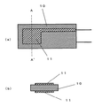
また、従来の酸素ポンプ素子を図8に示す。図8の(a)は酸素ポンプ素子の平面図、図8の(b)は図8(a)のA−A’線で切断した酸素ポンプ素子の断面図である。図において、10は酸素イオン伝導体である固体電解質層、11は電極であり、電極11は固体電解質層10の両面にそれぞれ1層が形成された構成の酸素ポンプ素子が開示されている。電極11は白金などの粒子を混合したペーストをスクリーン印刷などの方法を用いて塗布し、乾燥、焼成して形成されている。
【0005】
この酸素ポンプ素子は、特許文献1の酸素ポンプ装置と同様に作用する(例えば、特許文献2参照)。
【0006】
【特許文献1】
特開平11−23525号公報
【特許文献2】
特開平11−94792号公報
【0007】
【発明が解決しようとする課題】
しかしながら、特許文献1や特許文献2で開示されている白金微粒子の膜やスクリーン印刷による焼成膜で構成される電極は、膜の厚さが数十μm前後で、酸素分子との電極反応を活性化するために多孔質構造となっており、電気抵抗が高くなっている。このような電極では、例えば電極の外周部から直流電圧を印加した場合、電極の中央部は電気抵抗によって電圧が降下するため、酸素分子との電極反応(酸素の解離吸着とイオン化)が低下し、酸素イオンの輸送量が少なくなるという問題があった。特に、酸素ポンプ素子が大きい場合は、電極面積が大きくなるので電圧降下が著しく大きくなり、電極面全体を有効に機能させることができなくなる。また、電圧降下を防止するため、白金微粒子の電極膜を厚くすると電極膜自身の多孔質項構造が失われ、酸素分子との電極反応が低下し、全体として酸素イオンの輸送量が少なくなるという問題があった。
【0008】
また、特許文献2の酸素ポンプ装置の構成では、酸素ポンプ素子2と加熱手段7が大気に解放された状態にあるので、加熱手段7からの熱エネルギーは酸素ポンプ素子2だけでなく大気中の空気の加熱にも使われ、その結果、熱効率が悪くなり、酸素ポンプ素子を作動させる温度に昇温させるのに必要な加熱手段7の消費電力が高くなるとともに、前述した電極面の電圧降下の問題と合わせて酸素ポンプ素子の酸素イオンの輸送効率が悪いという課題を有していた。また、実施例では加熱手段7は酸素ポンプ素子2の上部に配置されているので、酸素ポンプ素子2の加熱は輻射熱がほとんどで、加熱された空気の対流熱を利用できないという欠点を有する。
【0009】
本発明は、前記従来の課題を解決するもので、電極面の電気抵抗を小さくし、印加する電圧の降下を抑制するとともに、酸素分子との電極反応をより高めることにより、電極面全体を有効に機能させる酸素ポンプ素子を提供するとともに、加熱手段からの熱を効率よく酸素ポンプ素子に伝達し、加熱に必要な電力を低減する酸素ポンプ装置を提供することを目的とする。
【0010】
【課題を解決するための手段】
前記従来の課題を解決するために、本発明の酸素ポンプ素子は、酸素イオン伝導性基板と、前記酸素イオン伝導性基板の両面に形成された主成分が酸素分子の解離吸着作用を有する金属酸化物粒子と前記金属酸化物粒子よりも導電性の高い金属粒子からなる第1電極膜と、前記第1電極膜の表面に形成された前記第1電極膜よりも導電性の高い金属粒子からなる第2電極膜とを設けた構成としたものである。
【0011】
第1電極膜よりも導電性の高い第2電極膜を設けることにより、電源からの電圧を第1電極膜の全面に電圧降下させることなく印加することができるとともに、第1電極膜に存在する金属酸化物粒子より導電性の高い金属粒子が金属酸化物粒子に第2電極膜からの電圧を効率よく供給することができるので解離吸着作用を有する金属酸化物粒子の酸素分子の原子化反応と原子化された酸素のイオン化反応を活性化させることができ、酸素子ポンプ素子の酸素イオン伝導性を向上させることができる。
【0012】
【発明の実施の形態】
請求項1に記載の発明は、酸素イオン伝導性基板の両面に主成分が酸素分子の解離吸着作用を有する金属酸化物粒子とこの金属酸化物粒子よりも導電性の高い金属粒子からなる第1電極膜とさらにその上に第1電極膜よりも導電性の高い金属粒子からなる第2電極膜を設けることにより、第2電極膜によって電源からの電圧を第1電極膜の全面に電圧降下させることなく印加することができる。また、第2電極膜を拡散して通過した酸素分子は第1電極膜に存在する金属酸化物粒子の触媒的作用により原子化反応が活性化されるとともに、第2電極から印加された電圧が第1電極膜に存在する金属粒子を通して隣接した解離吸着作用を有する金属酸化物粒子に供給されるので原子化された酸素のイオン化反応が活性化され、酸素ポンプ素子の酸素イオン伝導性を向上させることができる。また、第1電極膜、第2電極膜での電圧降下が抑制できることにより、第1電極膜、第2電極膜の自己発熱による温度分布を少なくすることができるので酸素ポンプ素子のクラックなどの破損が抑制され、優れた耐久性を実現することができる。
【0013】
請求項2に記載の発明は、酸素イオン伝導性基板の両面に主成分が酸素分子の解離吸着作用を有する金属酸化物粒子とこの金属酸化物粒子よりも導電性の高い金属粒子からなる第1電極膜とさらにその上に第1電極膜よりも導電性の高い金属粒子からなる第2電極膜を設けた酸素ポンプ素子と、酸素イオン伝導性基板の両面の電極膜を区画する区画手段と、酸素ポンプ素子を加熱する少なくとも一つの加熱手段と、酸素ポンプ素子と区画手段と加熱手段を囲むように配置された通気機能を有する断熱材とで構成することにより、酸素ポンプ素子と加熱手段が大気に直接触れることがないので加熱手段による酸素ポンプ素子への熱効率が向上し、酸素ポンプ素子の加熱に必要な電力を小さくすることができ、省エネルギー化を図ることができる。また、酸素ポンプ素子全体を均一に加熱することができるので、酸素ポンプ素子の破損防止効果が一層向上し、前述の第1電極膜と第2電極膜での電圧降下の抑制効果と合わせて酸素ポンプ素子の優れた性能を長期にわたり維持することができる。また、酸素ポンプ素子、区画手段、加熱手段が通気機能を有する断熱材に覆われた簡素な構造とすることができるので酸素ポンプの小型化が可能となり、機器への実装を容易にすることができる。
【0014】
請求項3に記載の発明は、酸素分子の解離吸着作用を有する金属酸化物としてペロブスカイト型構造を有する複合酸化物を用いる構成とすることにより、酸素分子の電極反応を高めるとともに耐熱性を向上させることができるので優れた酸素イオン伝導性を実現できるとともにその性能を長期間維持することができる。
【0015】
請求項4に記載の発明は、ペロブスカイト型構造を有する複合酸化物をAサイトにランタン、サマリウムの少なくとも1種と、Bサイトにコバルト、鉄、マンガンの少なくとも1種で構成している。
【0016】
請求項5に記載の発明は、ペロブスカイト型構造を有する複合酸化物のAサイトの一部をストロンチウムで置換して構成している。
【0017】
請求項4と5の構成とすることにより、酸素分子の電極反応を一層高めることができるので酸素ポンプ素子の酸素イオン伝導性を向上させることができる。
【0018】
請求項6に記載の発明は、金属酸化物粒子よりも導電性の高い金属粒子として少なくとも白金、金、銀、パラジウム、ルテニウム、ロジウム、ニッケルの1種を用いる構成としている。
【0019】
請求項7に記載の発明は、第1電極膜よりも導電性の高い金属粒子として少なくとも白金、金、銀、パラジウム、ルテニウム、ロジウム、ニッケルの1種を用いる構成としている。
【0020】
請求項6と7の構成とすることにより電気抵抗が低く、耐熱性の高い電極膜を得ることができるので優れた酸素ポンプの性能と耐久性を実現することができる。
【0021】
請求項8に記載の発明は、第1電極膜を酸素分子の解離吸着作用を有する金属酸化物粒子とこの金属酸化物粒子よりも導電性の高い金属粒子と金属酸化物からなるバインダーの混合物を焼成して得られる焼成膜で構成している。
【0022】
請求項9に記載の発明は、第2電極膜を第1電極膜よりも導電性の高い金属粒子と金属酸化物からなるバインダーの混合物を焼成して得られる焼成膜で構成している。
【0023】
請求項8と9の構成とすることにより、密着性に優れた第1電極膜と第2電極膜を形成することができるのでヒートショックなどの耐熱衝撃性に優れた酸素ポンプ素子を提供することができ、かつ長期にわたり酸素ポンプとしての性能を維持することができる。
【0024】
請求項10に記載の発明は、金属酸化物からなるバインダーとして酸化ビスマスを用いることにより、電極膜の酸素分子の拡散抵抗、および電極膜で原子化、イオン化された酸素の酸素イオン伝導性基板への拡散抵抗を低くすることができるので酸素イオン伝導性の低下を抑制することができる。
【0025】
【実施例】
以下、本発明の実施例について、図1〜6を参照しながら説明する。
【0026】
(実施例1)
図1は、本発明の第1の実施例における酸素ポンプ素子の構成図であり、図1(a)は断面図、(b)は平面図である。図1において、21は酸素イオン伝導性基板であり、イットリウムをドープしたジルコニア(YSZ)系、サマリウムをドープしたセリア系(SDC)、ランタンガレート系の材料が用いられる。22は酸素イオン伝導性基板21の両面に形成した第1電極膜、23は第1第1電極膜22の表面に形成された第2電極膜であり、第1電極膜22、第2電極膜23は密着性を強固にするための金属酸化物からなるバインダーを混合したペーストを印刷、焼成した多孔質の膜で構成される。電極膜23には、酸素ポンプ駆動電源(図示せず)からの電圧を酸素ポンプ素子に印加するためのリード部材24がそれぞれ接続されている。
【0027】
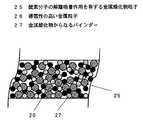
図2は、図1の酸素ポンプ素子の第1電極膜22の断面図であり、第1電極膜22を構成する各粒子の状態を模式的に示している。図2で示すように、第1電極膜22は酸素分子の解離吸着作用を有する金属酸化物粒子25、金属酸化物粒子25よりも導電性の高い金属粒子26、金属酸化物からなるバインダー27で構成され、それらの粒子が分散した状態となっている。
【0028】
図3は、図1の酸素ポンプ素子の第2電極膜23の断面図であり、第2電極膜23を構成する各粒子の状態を模式的に示しており、図2と同一材料は同一符号を付けている。図3で示すように、第2電極膜23は第1電極膜22よりも導電性の高い金属粒子26金属酸化物からなるバインダー27で構成され、それらの粒子が分散した状態となっている。
【0029】
以上のように構成された酸素ポンプ素子について、以下その動作、作用を説明する。
【0030】
酸素ポンプ素子を加熱手段によって酸素ポンプとして作動する温度に加熱する。次に酸素ポンプ駆動電源からリード部材24を介して第2電極膜23の一方をカソード、他方をアノードとして電圧が印加される。酸素イオン伝導性基板21が500〜800℃に昇温すると、カソード側の第1電極膜22では以下の電極反応が起こると考えられる。カソード側の空間に存在する酸素分子が第2電極膜23と第1電極膜22の多孔質の膜を拡散し、酸素分子は主として第1電極膜22に存在する酸素分子の解離吸着作用を有する金属酸化物粒子24によって解離吸着され、原子化される。駆動電源からの電圧が第2電極膜23を通して第1電極膜22含まれる金属酸化物粒子24よりも導電性に優れた金属粒子25に印加されることにより、金属酸化物粒子24に吸着している酸素原子および金属酸化物粒子24よりも導電性に優れた金属粒子25に拡散した酸素原子は電子をもらって酸素イオンとして酸素イオン伝導性基板21に取り込まれる。一方、酸素イオンは酸素イオン伝導性基板21中を移動し、アノード側の第1電極膜22に到達する。第1電極膜22に到達した酸素イオンはカソード側と逆の電極反応により酸素分子となり、第1電極膜22と第2電極膜23の多孔質の膜を拡散し外部空間に放出される。
【0031】
第2電極膜23は第1電極膜22より導電性が高いので電源からの電圧を第1電極膜22の全面に電圧降下させることなく印加することができ、第1電極膜22の面全体を有効に機能させることができる。
【0032】
また、第2電極膜23を拡散して通過した酸素分子は第1電極膜に存在する金属酸化物粒子25の触媒的作用により原子化反応が活性化されるとともに、第2電極23から印加された電圧が第1電極膜22に存在する金属粒子26を通して隣接した金属酸化物粒子25に供給されるので原子化された酸素のイオン化反応が活性化され、酸素ポンプ素子の酸素イオン伝導性を向上させることができる。
【0033】
また、第1電極膜22、第2電極膜23の面方向の電圧降下を抑制できることにより、第1電極膜22、第2電極膜23自身の自己発熱による温度分布を少なくすることができるので酸素ポンプ素子のクラックなどの破損が抑制され、優れた耐久性を実現することができる。また、第1電極膜22は酸素分子の原子化などの電極反応性を高くする金属酸化物粒子25を含むことにより、酸素分子の原子化反応を活性化することができるのでより高い酸素イオン伝導性を実現することができる。
【0034】
次に、本発明の具体的効果について図4、図5を用いて説明する。
【0035】
酸素イオン伝導性基板21として直径21mm、厚さ0.3mmのランタンガレート系固体電解質((La0.8SrSr0.2)(Ga0.8Mg0.2)O3)を用い、この酸素イオン伝導性基板21の両面に、酸素分子の解離吸着作用を有する金属酸化物粒子25としてペロブスカイト型複合酸化物(Sm0.5Sr0.5CoO3)粒子、この金属酸化物粒子25よりも導電性の高い金属粒子26として金(Au)の微粒子、有機溶剤、金属酸化物からなるバインダー27として酸化ビスマス(Bi2O3)の粒子、セルロース系ビヒクルを用い、これを混合したペーストをスクリーン印刷により印刷膜を形成し、乾燥、焼成することにより直径16mmで膜厚10〜20μmの第1電極膜22を形成した。このとき、ペロブスカイト型複合酸化物粒子と金微粒子は、1:1の比率とした。次に、第1電極膜22のそれぞれの表面に金属粒子26として金(Au)の微粒子、有機溶剤、金属酸化物からなるバインダー27として酸化ビスマス(Bi2O3)の粒子、セルロース系ビヒクルを用い、これを混合したペーストをスクリーン印刷により印刷膜を形成し、乾燥、焼成することにより直径16mmで膜厚10〜20μmの第2電極膜23を形成した。第2電極膜23は、第1電極膜22の金属酸化物微粒子25を含まないため、第1電極膜22よりも導電性が高い電極膜とすることができる。
【0036】
図4は、本発明の酸素ポンプ素子のV−I特性を測定する回路構成図である。図4で示すように電源28からの直流電圧は、リード部材24介して第2電極膜23に印加される構成とした。
【0037】
以上のように構成した酸素ポンプ素子について、図4に示す回路で直流電圧を印加し、V−I特性を評価した。図5は、本発明の実施例である酸素ポンプ素子のV−I特性の示すグラフであり、比較のため、本発明の第1電極膜22のみの構成とした酸素ポンプ素子(比較例)のV−I特性も示している。図5で明らかなように、本発明の酸素ポンプ素子は電圧に対して酸素イオンによるイオン電流が比較例の酸素ポンプ素子よりも大きくなっている。
【0038】
第1電極膜22、第2電極膜23に用いられる導電性の高い金属粒子26としては、金の他に白金、銀、パラジウム、ルテニウム、ロジウム、ニッケルがあげられ、少なくとも1種を用いることにより、金とほぼ同等の効果を得ることができるとともに、耐熱性の高い電極膜を得ることができるので優れた酸素ポンプの性能と耐久性を実現することができる。
【0039】
また、第1電極膜22を酸素分子の解離吸着作用を有する金属酸化物粒子25と金属酸化物粒子25よりも導電性の高い金属粒子26と金属酸化物からなるバインダー27の混合物を焼成して得られる焼成膜、および第2電極膜23を第1電極膜22よりも導電性の高い金属粒子26と金属酸化物からなるバインダー27の混合物を焼成して得られる焼成膜で構成することにより、優れた密着性を実現することができるのでヒートショックなどの耐熱衝撃性に優れた酸素ポンプ素子を提供することができ、かつ長期にわたり酸素ポンプとしての性能を維持することができる。
【0040】
また、金属酸化物からなるバインダー27として酸化ビスマスを用いることにより、第2電極膜23での酸素分子の拡散抵抗、および第1電極膜22で原子化、イオン化された酸素の酸素イオン伝導性基板への拡散抵抗を低くすることができるので酸素イオン伝導性の低下を抑制することができる。
【0041】
また、解離吸着作用を有する金属酸化物粒子25としては、酸素分子との電極反応高めるとともに高い耐熱性を有するペロブスカイト型構造を有する複合酸化物が適しており、優れた酸素イオン伝導性を実現できるとともにその性能を長期間維持することができる。
【0042】
特に、ペロブスカイト型複合酸化物の中でもAサイトにランタン、サマリウムの少なくとも1種と、Bサイトにコバルト、鉄、マンガンの少なくとも1種で構成されるもの、また、Aサイトの一部をストロンチウムで置換したものが優れた導電性、酸素との電極反応性を有している。
【0043】
(実施例2)
図6は、本発明の第2の実施例における酸素ポンプ装置の断面図である。図6において、29は酸素ポンプ素子であり、酸素ポンプ素子29は実施例1で述べた構成のものが用いられる。図6中、酸素ポンプ素子29は実施例1の酸素ポンプ素子の符号を付し、説明は省略する。
【0044】
図6において、30は酸素イオン伝導性基板21の両面に形成している第1電極膜22、第2電極膜23を区画する区画手段であり、第2電極膜23に対向する開口部を有しており、酸素イオン伝導性基板21とガラスなどの耐熱性を有する接着材料によって接着されている。区画手段30としては、ニッケル、鉄−クロム合金、チタン、金、白金などの金属板もしくは箔、アルミナ、ムライトなどのセラミック板が用いられるが、酸素イオン伝導性基板21との熱膨脹差が少なく、熱歪みが小さいことが要求されることから、ニッケル、鉄−クロム合金の金属箔が適用される。31は酸素ポンプ素子29の下部に設けられた加熱手段であり、加熱手段31に電力を印加する加熱用電源32にリード線33を介して接続されている。加熱手段31としては、鉄−クロム合金、ニッケル−クロム合金などの電熱線や箔が用いられる。
【0045】
34は通気機能を有する断熱材であり、多数の連通孔を有する多孔体で構成され、酸素ポンプ素子29、区画手段30、加熱手段31の周囲を覆うように配置されており、大気からの空気と大気への酸素の流出が可能となるように開口部を設けた筐体35に収納されている。この通気機能を有する断熱材34としては主成分が無機酸化物のシリカ粒子の集合体が用いられる。
【0046】
以上のように構成された酸素ポンプ装置について、以下その動作、作用を説明する。
【0047】
まず、加熱用電源32によって電力が加熱手段31に印加されると、加熱手段31は酸素ポンプ素子29を加熱する。次に酸素ポンプ素子29に酸素ポンプ駆動電源36からリード部材24を介してそれぞれの第2電極膜23に所定の電圧が印加される。本実施例の場合、下方の第2電極膜23をカソード、上方の第2電極膜23をアノードとしている。この状態で加熱手段31によって酸素ポンプ素子29が500〜800℃に昇温すると、カソード側の空間に存在する酸素分子が第1電極膜22で解離吸着し、酸素イオンとして酸素イオン伝導性基板21に取り込まれてアノード側の第1電極膜22に運ばれる。アノード側の第1電極膜22に到達した酸素イオンは酸素分子となり、第1電極膜22、第2電極膜23を拡散し外部空間に放出される。カソード側とアノード側の空間は区画手段30で分離されているので常にカソード側の空間に存在する酸素分子をアノード側の空間に輸送することができる。カソード側の空間の酸素分子がアノード側の空間に輸送されると、カソード側の酸素濃度が減少するが大気中の酸素分子を含む空気が通気機能を有するカソード側の断熱材34の連通孔を拡散し、カソード側の空間に流入する。一方、アノード側の空間からは第2電極膜23から放出された酸素分子がアノード側の通気機能を有する断熱材34を拡散し、大気中に流出する。酸素ポンプ素子29が動作している間、図中矢印で示すように酸素分子が輸送され続ける。このとき、カソード側に密閉となるように容器を取り付けると、容器内の酸素濃度を下げることができる。
【0048】
以上のように、通気機能を有する断熱材34が酸素ポンプ素子29と空間を区画する区画手段30と酸素ポンプ素子29を加熱する加熱手段31とを囲むように配置された構成とすることにより、酸素ポンプ素子29と加熱手段31が大気に直接触れことがないので熱効率が向上し、酸素ポンプ素子29の加熱に必要な電力を小さくすることができ、省エネルギー化を図ることができる。また、酸素ポンプ素子29全体を均一に加熱することができるとともに、第1電極膜22、第2電極膜23の電圧降下の抑制作用によりそれぞれの電極膜の自己発熱による温度分布を抑制することができるので酸素ポンプ素子29のクラックなどによる破損が防止され、酸素ポンプ装置の耐久性、信頼性を向上させることができる。また、酸素ポンプ素子29、区画手段30、加熱手段31が通気機能を有する断熱材34に覆われた簡素な構造とすることができるので酸素ポンプの小型化を図ることができ、機器への実装を容易にすることができる。
【0049】
また、特に本実施例のように通気機能を有する断熱材34を多数の連通孔を有する多孔質体で構成することにより、空気や酸素分子が十分な通気量を確保することができるとともに、酸素ポンプ素子29へ導入する空気は多孔質体の連通孔を通過しながら徐々に加熱されるので酸素ポンプ素子29の冷却が抑制され、加熱手段31の熱効率をさらに高めることができる。
【0050】
なお、本発明の酸素ポンプ装置は、食品保存庫などの低酸素雰囲気を必要とする機器や、逆に大気中よりも高い酸素濃度を必要とする機器に適用される。
【0051】
【発明の効果】
以上のように、本発明によれば、酸素ポンプ素子の電極膜の面全体で酸素分子との電極反応を起こさせることができるので酸素ポンプ素子の酸素イオン伝導性を向上させることができ、酸素ポンプとしての性能を向上させることができるとともに、電極膜の面での電圧降下を抑制できることにより、電極膜の自己発熱による温度分布を少なくすることができるので酸素ポンプ素子のクラックなどの破損が抑制され、優れた耐久性を実現することができる。
【0052】
また、酸素ポンプ装置としては加熱手段による酸素ポンプ素子への熱効率を向上させることができるので酸素ポンプ素子の加熱に必要な電力を小さくすることができ、省エネルギー化を図ることができとともに、酸素ポンプ素子全体を均一に加熱することができるので酸素ポンプ素子のクラックなどの破損が防止され、酸素ポンプ装置の耐久性、信頼性を向上させることができる。また、酸素ポンプ装置を簡素な構造とすることができるので酸素ポンプの小型化を図ることができ、機器への実装を容易にすることができる。
【図面の簡単な説明】
【図1】(a)本発明の実施例1における酸素ポンプ素子の断面図
(b)本発明の実施例1における酸素ポンプ素子の平面図
【図2】本発明の第1電極膜の断面図
【図3】本発明の第2電極膜の断面図
【図4】本発明の実施例1における酸素ポンプ素子のV−I特性を測定する回路構成図
【図5】本発明の実施例1おける酸素ポンプ素子のV−I特性を示すグラフ
【図6】本発明の実施例2における酸素ポンプ装置の断面図
【図7】従来の特許文献1における酸素ポンプ装置の断面図
【図8】従来の特許文献2における酸素ポンプ素子の断面図
【符号の説明】
21 酸素イオン伝導性基板
22 第1電極膜
23 第2電極膜
25 酸素分子の解離吸着作用を有する金属酸化物粒子
26 導電性の高い金属粒子
27 金属酸化物からなるバインダー
29 酸素ポンプ素子
30 区画手段
31 加熱手段
34 通気機能を有する断熱材[0001]
TECHNICAL FIELD OF THE INVENTION
The present invention relates to an improvement in an electrode film of an oxygen pump element using an oxygen ion conductor and an oxygen pump device equipped with the oxygen pump element.
[0002]
[Prior art]
FIG. 7 shows a conventional oxygen pump device of this type. In FIG. 7,
[0003]
In this configuration, when the
[0004]
FIG. 8 shows a conventional oxygen pump element. FIG. 8A is a plan view of the oxygen pump element, and FIG. 8B is a cross-sectional view of the oxygen pump element taken along line AA ′ in FIG. In the figure,
[0005]
This oxygen pump element operates similarly to the oxygen pump device of Patent Document 1 (for example, see Patent Document 2).
[0006]
[Patent Document 1]
Japanese Patent Application Laid-Open No. 11-23525 [Patent Document 2]
JP-A-11-94792
[Problems to be solved by the invention]
However, the electrodes composed of a film of platinum fine particles and a fired film by screen printing disclosed in
[0008]
Further, in the configuration of the oxygen pump device of
[0009]
The present invention solves the above-mentioned conventional problems, and reduces the electrical resistance of the electrode surface, suppresses a drop in applied voltage, and further enhances the electrode reaction with oxygen molecules, thereby making the entire electrode surface effective. It is an object of the present invention to provide an oxygen pump device that functions as a pump device and that efficiently transmits heat from a heating unit to the oxygen pump device to reduce the power required for heating.
[0010]
[Means for Solving the Problems]
In order to solve the above-mentioned conventional problems, an oxygen pump element of the present invention comprises an oxygen ion conductive substrate, and a metal oxide having a main component formed on both surfaces of the oxygen ion conductive substrate having a dissociative adsorption function of oxygen molecules. A first electrode film made of metal particles having higher conductivity than the metal oxide particles and a metal particle having higher conductivity than the first electrode film formed on the surface of the first electrode film; This is a configuration in which a second electrode film is provided.
[0011]
By providing the second electrode film having higher conductivity than the first electrode film, a voltage from a power source can be applied to the entire surface of the first electrode film without causing a voltage drop, and is present in the first electrode film. Since the metal particles having higher conductivity than the metal oxide particles can efficiently supply the voltage from the second electrode film to the metal oxide particles, the atomization reaction of the oxygen molecules of the metal oxide particles having the dissociative adsorption function is performed. The ionization reaction of atomized oxygen can be activated, and the oxygen ion conductivity of the acid element pump element can be improved.
[0012]
BEST MODE FOR CARRYING OUT THE INVENTION
The first aspect of the present invention is directed to a first aspect in which a metal oxide particle whose main component has a dissociative adsorption function of oxygen molecules on both surfaces of an oxygen ion conductive substrate and a metal particle having higher conductivity than the metal oxide particle. By providing an electrode film and a second electrode film made of metal particles having higher conductivity than the first electrode film on the electrode film, a voltage from a power supply is dropped by the second electrode film over the entire surface of the first electrode film. Can be applied without any need. Oxygen molecules diffused and passed through the second electrode film activate the atomization reaction by the catalytic action of the metal oxide particles present in the first electrode film, and reduce the voltage applied from the second electrode. The metal ions present in the first electrode film are supplied to adjacent metal oxide particles having a dissociative adsorption function, so that the ionization reaction of atomized oxygen is activated and the oxygen ion conductivity of the oxygen pump element is improved. be able to. Further, since the voltage drop at the first electrode film and the second electrode film can be suppressed, the temperature distribution due to the self-heating of the first electrode film and the second electrode film can be reduced, so that the oxygen pump element can be damaged, such as cracks. Is suppressed, and excellent durability can be realized.
[0013]
According to a second aspect of the present invention, there is provided a semiconductor device comprising: a first metal oxide particle having a dissociative adsorption function of oxygen molecules on both surfaces of an oxygen ion conductive substrate; and a metal particle having higher conductivity than the metal oxide particle. An oxygen pump element provided with an electrode film and a second electrode film made of metal particles having higher conductivity than the first electrode film, and a partitioning means for partitioning the electrode films on both surfaces of the oxygen ion conductive substrate; By comprising at least one heating means for heating the oxygen pump element, and a heat insulating material having a ventilation function arranged so as to surround the oxygen pump element, the partition means, and the heating means, the oxygen pump element and the heating means can be heated to the atmosphere. The heat efficiency to the oxygen pump element by the heating means is improved because it is not directly touched, the electric power required for heating the oxygen pump element can be reduced, and energy saving can be achieved. Further, since the entire oxygen pump element can be uniformly heated, the effect of preventing damage to the oxygen pump element is further improved, and in addition to the effect of suppressing the voltage drop at the first electrode film and the second electrode film, the oxygen pump element can be heated. Excellent performance of the pump element can be maintained for a long time. In addition, since the oxygen pump element, the partitioning means, and the heating means can have a simple structure covered with a heat insulating material having a ventilation function, the size of the oxygen pump can be reduced, and mounting on the equipment can be facilitated. it can.
[0014]
The invention according to
[0015]
According to a fourth aspect of the present invention, the composite oxide having a perovskite structure is composed of at least one of lanthanum and samarium at the A site and at least one of cobalt, iron, and manganese at the B site.
[0016]
According to a fifth aspect of the present invention, a part of the A site of the complex oxide having a perovskite structure is substituted with strontium.
[0017]
According to the constitutions of
[0018]
The invention according to
[0019]
According to a seventh aspect of the present invention, at least one of platinum, gold, silver, palladium, ruthenium, rhodium, and nickel is used as the metal particles having higher conductivity than the first electrode film.
[0020]
According to the configurations of
[0021]
According to an eighth aspect of the present invention, the first electrode film is formed of a mixture of a metal oxide particle having a dissociative adsorption function of oxygen molecules, a metal particle having higher conductivity than the metal oxide particle, and a binder made of a metal oxide. It is composed of a fired film obtained by firing.
[0022]
In a ninth aspect of the present invention, the second electrode film is constituted by a fired film obtained by firing a mixture of a binder made of metal particles and a metal oxide having higher conductivity than the first electrode film.
[0023]
According to the constitution of
[0024]
According to a tenth aspect of the present invention, by using bismuth oxide as a binder made of a metal oxide, the diffusion resistance of oxygen molecules in the electrode film, and the oxygen atomized and ionized in the electrode film to the oxygen ion conductive substrate. , The diffusion resistance can be reduced, so that a decrease in oxygen ion conductivity can be suppressed.
[0025]
【Example】
Hereinafter, embodiments of the present invention will be described with reference to FIGS.
[0026]
(Example 1)
FIG. 1 is a configuration diagram of an oxygen pump element according to a first embodiment of the present invention. FIG. 1A is a sectional view, and FIG. 1B is a plan view. In FIG. 1,
[0027]
FIG. 2 is a cross-sectional view of the
[0028]
FIG. 3 is a cross-sectional view of the
[0029]
The operation and operation of the oxygen pump element configured as described above will be described below.
[0030]
The oxygen pump element is heated by the heating means to a temperature at which it operates as an oxygen pump. Next, a voltage is applied from an oxygen pump driving power source via the
[0031]
Since the
[0032]
Oxygen molecules diffused and passed through the
[0033]
Further, since the voltage drop in the surface direction of the
[0034]
Next, specific effects of the present invention will be described with reference to FIGS.
[0035]
A lanthanum gallate-based solid electrolyte ((La 0.8 SrSr 0.2 ) (Ga 0.8 Mg 0.2 ) O 3 ) having a diameter of 21 mm and a thickness of 0.3 mm was used as the oxygen ion
[0036]
FIG. 4 is a circuit configuration diagram for measuring the VI characteristics of the oxygen pump element of the present invention. As shown in FIG. 4, a DC voltage from a
[0037]
With respect to the oxygen pump element configured as described above, a DC voltage was applied by the circuit shown in FIG. 4 and the VI characteristics were evaluated. FIG. 5 is a graph showing the VI characteristics of the oxygen pump element according to the example of the present invention. For comparison, an oxygen pump element (comparative example) having only the
[0038]
Examples of the highly
[0039]
The
[0040]
Further, by using bismuth oxide as the
[0041]
In addition, as the
[0042]
In particular, among the perovskite-type composite oxides, the A site is composed of at least one of lanthanum and samarium and the B site is composed of at least one of cobalt, iron and manganese, and a part of the A site is substituted with strontium. The resulting material has excellent conductivity and electrode reactivity with oxygen.
[0043]
(Example 2)
FIG. 6 is a sectional view of the oxygen pump device according to the second embodiment of the present invention. In FIG. 6,
[0044]
In FIG. 6,
[0045]
[0046]
The operation and operation of the oxygen pump device configured as described above will be described below.
[0047]
First, when electric power is applied to the heating means 31 by the
[0048]
As described above, the
[0049]
In addition, in particular, by forming the
[0050]
Note that the oxygen pump device of the present invention is applied to a device requiring a low oxygen atmosphere such as a food storage or a device requiring a higher oxygen concentration than the atmosphere.
[0051]
【The invention's effect】
As described above, according to the present invention, an electrode reaction with oxygen molecules can be caused on the entire surface of the electrode film of the oxygen pump element, so that the oxygen ion conductivity of the oxygen pump element can be improved. The performance as a pump can be improved, and the voltage drop on the electrode film can be suppressed, so that the temperature distribution due to the self-heating of the electrode film can be reduced, so that the damage such as cracks of the oxygen pump element is suppressed. Thus, excellent durability can be realized.
[0052]
Further, the oxygen pump device can improve the heat efficiency of the oxygen pump element by the heating means, so that the power required for heating the oxygen pump element can be reduced, and energy saving can be achieved. Since the entire element can be heated uniformly, damage such as cracks of the oxygen pump element can be prevented, and the durability and reliability of the oxygen pump device can be improved. In addition, since the oxygen pump device can have a simple structure, the size of the oxygen pump can be reduced, and mounting on the device can be facilitated.
[Brief description of the drawings]
FIG. 1A is a cross-sectional view of an oxygen pump element according to a first embodiment of the present invention. FIG. 1B is a plan view of an oxygen pump element according to a first embodiment of the present invention. FIG. FIG. 3 is a cross-sectional view of a second electrode film of the present invention. FIG. 4 is a circuit configuration diagram for measuring VI characteristics of the oxygen pump element according to the first embodiment of the present invention. FIG. 6 is a graph showing VI characteristics of an oxygen pump element. FIG. 6 is a cross-sectional view of an oxygen pump device according to a second embodiment of the present invention. FIG. Sectional view of oxygen pump element in
Claims (10)
Priority Applications (1)
| Application Number | Priority Date | Filing Date | Title |
|---|---|---|---|
| JP2002298769A JP2004132876A (en) | 2002-10-11 | 2002-10-11 | Oxygen pump element and oxygen pump device |
Applications Claiming Priority (1)
| Application Number | Priority Date | Filing Date | Title |
|---|---|---|---|
| JP2002298769A JP2004132876A (en) | 2002-10-11 | 2002-10-11 | Oxygen pump element and oxygen pump device |
Publications (1)
| Publication Number | Publication Date |
|---|---|
| JP2004132876A true JP2004132876A (en) | 2004-04-30 |
Family
ID=32288085
Family Applications (1)
| Application Number | Title | Priority Date | Filing Date |
|---|---|---|---|
| JP2002298769A Pending JP2004132876A (en) | 2002-10-11 | 2002-10-11 | Oxygen pump element and oxygen pump device |
Country Status (1)
| Country | Link |
|---|---|
| JP (1) | JP2004132876A (en) |
-
2002
- 2002-10-11 JP JP2002298769A patent/JP2004132876A/en active Pending
Similar Documents
| Publication | Publication Date | Title |
|---|---|---|
| JP4395567B2 (en) | Electrochemical element and exhaust gas purification method | |
| JP2004212327A (en) | Oxygen pumping element and oxygen pumping apparatus using the same | |
| JP2004132876A (en) | Oxygen pump element and oxygen pump device | |
| JP2004269295A (en) | Oxygen pumping device and oxygen pumping apparatus on which oxygen pumping device is loaded | |
| JP2004232019A (en) | Oxygen pumping element and oxygen pumping device carrying the element | |
| JP2004232019A5 (en) | ||
| JP2004269295A5 (en) | ||
| JP5369471B2 (en) | Solid oxide fuel cell and method for producing the same | |
| JP4039200B2 (en) | Oxygen pump element and oxygen pump device | |
| JP2007103092A (en) | Solid oxide fuel cell | |
| JP2004131357A (en) | Oxygen pump element and oxygen pump | |
| JP5487899B2 (en) | Gas cracker | |
| JP3093647B2 (en) | Nitrogen oxide decomposition equipment | |
| JP2006218362A (en) | Oxygen pump | |
| JP2006258624A (en) | Method of controlling oxygen supply device | |
| JP4797434B2 (en) | Oxygen pump element and oxygen supply device using the same | |
| JP3846319B2 (en) | Oxygen pump | |
| JP2005315608A (en) | Oxygen pump element and oxygen feeder having element | |
| JP2006136812A (en) | Oxygen pump element and oxygen supply apparatus using the same | |
| JP2006137638A (en) | Oxygen pump | |
| JP2006161108A (en) | Oxygen pump element and oxygen feeding device using the same | |
| JP2006255158A (en) | Oxygen pump element and oxygen supplying device using it | |
| JP2005172495A (en) | Oxygen pumping device | |
| JP2005164529A (en) | Oxygen-pumping element | |
| JP2007119285A (en) | Oxygen feeder |
Legal Events
| Date | Code | Title | Description |
|---|---|---|---|
| A621 | Written request for application examination |
Free format text: JAPANESE INTERMEDIATE CODE: A621 Effective date: 20050926 |
|
| RD01 | Notification of change of attorney |
Free format text: JAPANESE INTERMEDIATE CODE: A7421 Effective date: 20051013 |
|
| A977 | Report on retrieval |
Free format text: JAPANESE INTERMEDIATE CODE: A971007 Effective date: 20070518 |
|
| A131 | Notification of reasons for refusal |
Free format text: JAPANESE INTERMEDIATE CODE: A131 Effective date: 20080819 |
|
| A02 | Decision of refusal |
Free format text: JAPANESE INTERMEDIATE CODE: A02 Effective date: 20081216 |