JP2004111968A - Heat sink with heat pipe directly brought into contact with component - Google Patents
Heat sink with heat pipe directly brought into contact with component Download PDFInfo
- Publication number
- JP2004111968A JP2004111968A JP2003319796A JP2003319796A JP2004111968A JP 2004111968 A JP2004111968 A JP 2004111968A JP 2003319796 A JP2003319796 A JP 2003319796A JP 2003319796 A JP2003319796 A JP 2003319796A JP 2004111968 A JP2004111968 A JP 2004111968A
- Authority
- JP
- Japan
- Prior art keywords
- heat
- heat pipe
- base
- heat sink
- pipe
- Prior art date
- Legal status (The legal status is an assumption and is not a legal conclusion. Google has not performed a legal analysis and makes no representation as to the accuracy of the status listed.)
- Withdrawn
Links
- 238000000034 method Methods 0.000 claims 2
- 238000004519 manufacturing process Methods 0.000 claims 1
- 238000001816 cooling Methods 0.000 description 8
- 239000000463 material Substances 0.000 description 7
- 239000003570 air Substances 0.000 description 6
- 239000000853 adhesive Substances 0.000 description 5
- 230000001070 adhesive effect Effects 0.000 description 5
- 230000000712 assembly Effects 0.000 description 4
- 238000000429 assembly Methods 0.000 description 4
- 230000000694 effects Effects 0.000 description 4
- 239000007788 liquid Substances 0.000 description 4
- 238000012546 transfer Methods 0.000 description 4
- 239000012080 ambient air Substances 0.000 description 3
- RYGMFSIKBFXOCR-UHFFFAOYSA-N Copper Chemical compound [Cu] RYGMFSIKBFXOCR-UHFFFAOYSA-N 0.000 description 2
- XAGFODPZIPBFFR-UHFFFAOYSA-N aluminium Chemical compound [Al] XAGFODPZIPBFFR-UHFFFAOYSA-N 0.000 description 2
- 229910052782 aluminium Inorganic materials 0.000 description 2
- 238000009835 boiling Methods 0.000 description 2
- 229910052802 copper Inorganic materials 0.000 description 2
- 239000010949 copper Substances 0.000 description 2
- 230000007423 decrease Effects 0.000 description 2
- 238000010586 diagram Methods 0.000 description 2
- 239000012530 fluid Substances 0.000 description 2
- 230000017525 heat dissipation Effects 0.000 description 2
- 239000007787 solid Substances 0.000 description 2
- 229910000838 Al alloy Inorganic materials 0.000 description 1
- 239000004593 Epoxy Substances 0.000 description 1
- 229910045601 alloy Inorganic materials 0.000 description 1
- 239000000956 alloy Substances 0.000 description 1
- 238000005452 bending Methods 0.000 description 1
- 230000005494 condensation Effects 0.000 description 1
- 238000009833 condensation Methods 0.000 description 1
- 238000011109 contamination Methods 0.000 description 1
- 238000007796 conventional method Methods 0.000 description 1
- 238000005260 corrosion Methods 0.000 description 1
- 230000007797 corrosion Effects 0.000 description 1
- 238000013500 data storage Methods 0.000 description 1
- 238000013461 design Methods 0.000 description 1
- 238000005265 energy consumption Methods 0.000 description 1
- 125000003700 epoxy group Chemical group 0.000 description 1
- 238000001704 evaporation Methods 0.000 description 1
- 230000008020 evaporation Effects 0.000 description 1
- 230000001771 impaired effect Effects 0.000 description 1
- 238000003754 machining Methods 0.000 description 1
- 238000012986 modification Methods 0.000 description 1
- 230000004048 modification Effects 0.000 description 1
- 238000013021 overheating Methods 0.000 description 1
- 230000002093 peripheral effect Effects 0.000 description 1
- 229920003023 plastic Polymers 0.000 description 1
- 239000004033 plastic Substances 0.000 description 1
- 229920000647 polyepoxide Polymers 0.000 description 1
- 238000012545 processing Methods 0.000 description 1
- 125000006850 spacer group Chemical group 0.000 description 1
- 239000000758 substrate Substances 0.000 description 1
- XLYOFNOQVPJJNP-UHFFFAOYSA-N water Substances O XLYOFNOQVPJJNP-UHFFFAOYSA-N 0.000 description 1
Images


Classifications
-
- H—ELECTRICITY
- H01—ELECTRIC ELEMENTS
- H01L—SEMICONDUCTOR DEVICES NOT COVERED BY CLASS H10
- H01L23/00—Details of semiconductor or other solid state devices
- H01L23/34—Arrangements for cooling, heating, ventilating or temperature compensation ; Temperature sensing arrangements
- H01L23/42—Fillings or auxiliary members in containers or encapsulations selected or arranged to facilitate heating or cooling
- H01L23/427—Cooling by change of state, e.g. use of heat pipes
-
- H—ELECTRICITY
- H05—ELECTRIC TECHNIQUES NOT OTHERWISE PROVIDED FOR
- H05K—PRINTED CIRCUITS; CASINGS OR CONSTRUCTIONAL DETAILS OF ELECTRIC APPARATUS; MANUFACTURE OF ASSEMBLAGES OF ELECTRICAL COMPONENTS
- H05K7/00—Constructional details common to different types of electric apparatus
- H05K7/20—Modifications to facilitate cooling, ventilating, or heating
- H05K7/2029—Modifications to facilitate cooling, ventilating, or heating using a liquid coolant with phase change in electronic enclosures
-
- F—MECHANICAL ENGINEERING; LIGHTING; HEATING; WEAPONS; BLASTING
- F28—HEAT EXCHANGE IN GENERAL
- F28D—HEAT-EXCHANGE APPARATUS, NOT PROVIDED FOR IN ANOTHER SUBCLASS, IN WHICH THE HEAT-EXCHANGE MEDIA DO NOT COME INTO DIRECT CONTACT
- F28D15/00—Heat-exchange apparatus with the intermediate heat-transfer medium in closed tubes passing into or through the conduit walls ; Heat-exchange apparatus employing intermediate heat-transfer medium or bodies
- F28D15/02—Heat-exchange apparatus with the intermediate heat-transfer medium in closed tubes passing into or through the conduit walls ; Heat-exchange apparatus employing intermediate heat-transfer medium or bodies in which the medium condenses and evaporates, e.g. heat pipes
- F28D15/0275—Arrangements for coupling heat-pipes together or with other structures, e.g. with base blocks; Heat pipe cores
-
- H—ELECTRICITY
- H01—ELECTRIC ELEMENTS
- H01L—SEMICONDUCTOR DEVICES NOT COVERED BY CLASS H10
- H01L2924/00—Indexing scheme for arrangements or methods for connecting or disconnecting semiconductor or solid-state bodies as covered by H01L24/00
- H01L2924/0001—Technical content checked by a classifier
- H01L2924/0002—Not covered by any one of groups H01L24/00, H01L24/00 and H01L2224/00
-
- H—ELECTRICITY
- H01—ELECTRIC ELEMENTS
- H01L—SEMICONDUCTOR DEVICES NOT COVERED BY CLASS H10
- H01L2924/00—Indexing scheme for arrangements or methods for connecting or disconnecting semiconductor or solid-state bodies as covered by H01L24/00
- H01L2924/30—Technical effects
- H01L2924/301—Electrical effects
- H01L2924/3011—Impedance
Landscapes
- Engineering & Computer Science (AREA)
- Physics & Mathematics (AREA)
- Microelectronics & Electronic Packaging (AREA)
- Thermal Sciences (AREA)
- Mechanical Engineering (AREA)
- Sustainable Development (AREA)
- Life Sciences & Earth Sciences (AREA)
- General Engineering & Computer Science (AREA)
- Condensed Matter Physics & Semiconductors (AREA)
- General Physics & Mathematics (AREA)
- Computer Hardware Design (AREA)
- Power Engineering (AREA)
- Cooling Or The Like Of Semiconductors Or Solid State Devices (AREA)
- Cooling Or The Like Of Electrical Apparatus (AREA)
Abstract
Description
本発明は、電子部品のヒートシンクに関する。本出願の相互関連出願は、「HEATSINK WITH HEAT PIPE AND BASE FINS」と題する一般特許出願の米国出願第10/246,322号(代理人整理番号100200242−1(1964−9−3))と、「HEATSINK WITH ANGLED HEAT PIPE」と題する米国出願第10/246,299号(代理人整理番号100200243−1(1964−10−3))に関連する。 The present invention relates to a heat sink for electronic components. A co-pending application of the present application is U.S. Application No. 10 / 246,322 (Attorney Docket No. 1002002242-1 (1964-9-3)), a general patent application entitled "Heatsink \ Heat \ Pipe \ And \ Base \ Fins". Related to U.S. Application No. 10 / 246,299, entitled "HEATSINK \ WITH \ ANGLED \ HEAT \ PIPE" (Attorney Docket Number 1002002243-1 (1964- 10-3)).
電子部品は、動作するときに熱を生成することは周知である。発生した熱が臨界温度よりも高くなると、電子部品の動作に障害が起こることがある。したがって、そのような障害を防ぐために、過剰な熱を放散させなければならない。 It is well known that electronic components generate heat when they operate. If the generated heat is higher than the critical temperature, the operation of the electronic component may be impaired. Therefore, excessive heat must be dissipated to prevent such disturbances.
熱を放散させるために使用される1つのタイプのヒートシンクには、ヒートパイプがある。ヒートパイプは、水などの熱伝達液体が充填され、ヒートパイプの内壁がウィッキング材料で覆われている真空に封止されたパイプである。電子部品が熱くなるとき、ヒートパイプの電子部品に最も近い「高温」端も熱くなる。ヒートパイプの高温端の近くにある液体は、最終的に蒸発し、得られた蒸気は、ヒートパイプの「低温」端に集まり、そこで蒸気が凝縮する。凝縮した液体は、ウィッキングを介してヒートパイプの高温端に戻る。蒸発した液体は、再び、ヒートパイプの低温端に移動する。この蒸発/凝縮サイクルは、ヒートパイプがきわめて効率的に熱を伝達するときに繰り返し、したがってヒートパイプの高温端は、低温端と同じ温度かまたはそれに近く維持される。さらに、流体の沸点は圧力によって変化するので、ヒートパイプ内の真空を、沸騰が所望の温度で起こるように設定することができる。 One type of heat sink used to dissipate heat is a heat pipe. A heat pipe is a vacuum-sealed pipe filled with a heat transfer liquid such as water and the inner wall of the heat pipe is covered with a wicking material. As the electronic component gets hot, the "hot" end of the heat pipe closest to the electronic component also gets hot. The liquid near the hot end of the heat pipe will eventually evaporate and the resulting vapor will collect at the "cold" end of the heat pipe where the vapor will condense. The condensed liquid returns to the hot end of the heat pipe via wicking. The evaporated liquid moves again to the cold end of the heat pipe. This evaporation / condensation cycle repeats when the heat pipe transfers heat very efficiently, so that the hot end of the heat pipe is maintained at or near the same temperature as the cold end. Further, since the boiling point of the fluid varies with pressure, the vacuum in the heat pipe can be set such that boiling occurs at the desired temperature.
ヒートパイプは、一般に、特定の電子部品用に設計されている。例えば、ヒートパイプのベースは、一般に、冷却する部品の表面領域と同じまたはほぼ同じ形状および領域である。したがって、様々な表面領域および/または形状を有する部品は、一般に、特にそのような特定の領域および形状のために設計されているヒートパイプを必要とする。部品の冷却に使用されるほとんどの従来技術のヒートパイプは、比較的大きい直径(1/4インチより大きい)を有する。さらに、このようなヒートパイプのベースは、長方形のことがあり、またヒートパイプ自体は、ベースパイプ界面が複雑な設計になることがあるように円形である。例えば、長方形のベースは、円筒形のヒートパイプの内側を連結する中空の内部を有することがある。代替として、ベースは、ベースに取り付けられたヒートパイプとつながっている。しかしながら、これは、ベースと、ヒートパイプをベースに取り付けるために使用される材料(例えば、接着材)の熱抵抗が高くなるためあまり効率的でない。 Heat pipes are generally designed for specific electronic components. For example, the base of a heat pipe is generally the same or approximately the same shape and area as the surface area of the component to be cooled. Accordingly, components having various surface areas and / or shapes generally require heat pipes specifically designed for such specific areas and shapes. Most prior art heat pipes used to cool parts have a relatively large diameter (greater than 1/4 inch). Further, the base of such a heat pipe may be rectangular, and the heat pipe itself is circular, such that the base pipe interface may be a complex design. For example, a rectangular base may have a hollow interior connecting the inside of a cylindrical heat pipe. Alternatively, the base is connected to a heat pipe attached to the base. However, this is not very efficient due to the high thermal resistance of the base and the material (eg, adhesive) used to attach the heat pipe to the base.
ヒートパイプの直径は、ヒートシンク・アセンブリを介した熱伝達の量に影響する。ヒートパイプの投影平面面積は、その直径と共に増大し、その直径が大きくなると、空気がパイプ内に循環するように強制的に流され、それにより、空気の冷却効果が弱まるので、空気抵抗が大きくなる。 The heat pipe diameter affects the amount of heat transfer through the heat sink assembly. The projected plane area of the heat pipe increases with its diameter, and as its diameter increases, air is forced to circulate through the pipe, thereby reducing the cooling effect of the air and increasing the air resistance. Become.
ヒートパイプのさらにもう1つの問題は、恐らくウィッキング材料の腐食、流体の汚染などによって真空圧力が低下するように漏れを形成することによってヒートパイプが故障する可能性があることである。その結果、ヒートパイプが故障したとき、電子部品から周囲の環境に熱を伝達する効果が下がり、したがって、部品を冷却する効果が低下する。ヒートパイプの故障が十分に大きくなると、部品は過熱したり故障したりすることがある。 Yet another problem with heat pipes is that heat pipes can fail by forming leaks that reduce vacuum pressure, presumably due to wicking material corrosion, fluid contamination, and the like. As a result, when the heat pipe breaks down, the effect of transferring heat from the electronic component to the surrounding environment decreases, and therefore, the effect of cooling the component decreases. If the heat pipe failure is large enough, the component may overheat or fail.
本発明の実施形態によれば、ヒートシンクは、ヒートパイプと、ヒートパイプが空気の隙間なしに部品と直接接触するようにヒートパイプを熱発生部品に取り付けるように適合された基部とを含む。 According to an embodiment of the present invention, a heat sink includes a heat pipe and a base adapted to attach the heat pipe to the heat generating component such that the heat pipe is in direct contact with the component without air gaps.
ヒートパイプは、部品と直接接触することによって、中実な基部を介して部品に結合された場合よりも高い効率で熱を放散する。さらに、そのようなヒートシンクは、中空の基部を備えたヒートシンクよりも安価な可能性がある。さらに、ヒートパイプを曲げて、ヒートパイプが部品と接触する部分を最大にし、それによりヒートパイプによって実現される冷却効果を高めることができる。さらに、このヒートシンクは、単一のより大きいヒートパイプを備えたヒートシンクよりもコストを削減し、冗長性を高めかつ空気流抵抗を小さくするために複数のヒートパイプを含むことができる。 Heat pipes dissipate heat more efficiently by direct contact with the component than when coupled to the component via a solid base. Further, such a heat sink may be less expensive than a heat sink with a hollow base. In addition, the heat pipe can be bent to maximize the point where the heat pipe contacts the component, thereby increasing the cooling effect provided by the heat pipe. In addition, the heat sink can include multiple heat pipes to reduce cost, increase redundancy, and reduce airflow resistance over a heat sink with a single, larger heat pipe.
以下の説明は、当業者が本発明を作成し使用できるようにするために提示される。開示された実施形態に対する様々な修正は、当業者には容易に明らかになり、本明細書における包括的な原理は、併記された特許請求の範囲によって定義されるような本発明の趣旨および範囲から逸脱することなく他の実施形態および応用例に適用することができる。したがって、本発明は、示した実施形態に限定されるものではなく、本明細書に開示した原理と特徴と一致する最も広い範囲があたえられるべきである。 The following description is presented to enable one of ordinary skill in the art to make and use the invention. Various modifications to the disclosed embodiments will be readily apparent to those skilled in the art, and the generic principles herein are set forth in the spirit and scope of the invention as defined by the appended claims. The present invention can be applied to other embodiments and application examples without departing from the present invention. Therefore, the present invention is not limited to the embodiments shown, but is to be accorded the widest scope consistent with the principles and features disclosed herein.
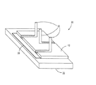
図1は、本発明の実施形態によるヒートシンク5の等角図である。ヒートシンク5は、複数のヒートパイプを含むが、代替の実施形態は、1つのヒートパイプだけを含む。この実施形態によれば、ベース12に取り付けられた2つのヒートパイプ10がある。ヒートパイプ10は、接着材、はめ込み(「スナップ留め」)、ベルト留め、ボルト留めなどを含む、任意の従来の方式でベース12に取り付けられる。
FIG. 1 is an isometric view of a
ベース12は、例えばプリント回路基板(図示せず)に取り付けられた電子部品のような熱発生部品に取り付けられるような適切な任意の形状のものである。熱発生部品は、望ましくない熱を生成する可能性がある任意の装置であり、最も一般には、例えば中央処理装置などの電子部品である。ベース12は、一体物であり、すなわち、熱を伝導する傾向が高い材料の連続体として形成されるが、ベース12は、複数の接合部品、すなわち非一体物で形成されてもよい。
The
ベース12は、アルミニウム、銅、その他の合金、プラスチック、エポキシなどの材料および/または適切な熱伝達材料などから形成することができる。1つの実施形態において、ベース12は、アルミニウム合金の連続片から形成され、その最下部は、1つまたは複数の電子部品の輪郭に適合するように形成されている。もう1つの実施形態において、ベース12は、例えば第1の領域のアルミニウムや第2の領域の銅のような2つの異なる材料から形成される。2つの領域は、ボルト締めや熱伝導接着材などによる従来の手段によって接合される。
The
ヒートシンク5は、また、従来の対流熱放散のような、周囲空気冷却効果を高めるために、ベース12に取り付けられかつヒートシンクの表面積を大きくするように意図された垂直フィン11を含む。周囲空気の表面接触を増大させることによって、熱は、電子部品からヒートシンクを介して周囲空気へと、より効率的に放散される。この実施形態において、垂直フィン11は、少なくともヒートパイプ10の屈曲部まで延在する。垂直フィン11は、また、ベース12の厚さを減少させ、それによりコストが減少し、冷却が効率が高まる。垂直フィン11は、固体のベース・ブロックを機械加工するか(例えば、一体物のフィンまたは削ったフィン)、従来の方法でベース12に取り付けられる(例えば、折りたたみフィン)ことによって形成される。
The
前に説明したように、垂直フィン11は、ベース12から、ヒートパイプ10の屈曲部が止まる場所まで形成される。したがって、第2組の水平フィン18を、ヒートパイプ10のまわりに配置することができ、水平フィン18は、水平フィン18がヒートシンク5に取り付けられたときに垂直フィン11と接触する。水平フィン18は、一般に、パイプ10に押し付けられるプレスオン・フィンである。習慣によって、水平フィンは、組み立てられたときに摩擦が水平フィン18を適所に保持し、フランジ・スペーサが水平フィンの間に空間を維持するために使用されるそのような、1つまたは複数のヒートパイプ10のまわりにぴったりと合うように機械加工されたフィンである。代替として、水平フィン18は、接着材やバンド留めなどの別の従来の方式で取り付けられる。水平フィン18は、ヒートシンク5から取り外すことができる。垂直フィン11と水平フィン18をすべてのヒートパイプ10の垂直方向の長さに沿って位置決めすることによって、ヒートシンク5の熱効率が向上する。
As described above, the
さらに図1を参照すると、2つのヒートパイプ10は、ベース12が、各ヒートパイプ10の低温端13をベースの下面と実質的に垂直に位置合わせし、ヒートパイプ10の高温端14をベースの下面と実質的に平行に位置合わせするようにベースに取り付けられる。さらに、各ヒートパイプ10の高温端14は、ヒートシンクが取り付けられている任意の熱発生部品が、各ヒートパイプ10の高温端14と直接接触するように、ベース12の下部に沿って露出される。1つの実施形態において、各ヒートパイプ10の高温端14は、平坦でありかつベース12の下部と同じ高さである。ヒートシンク5を、ベース12の下部から露出された各ヒートパイプの高温端14に取り付けることによって、熱発生部品と直接接触させることによって熱放散効率を高めることができる。ベース12の下部平面の残りの部分は、さらに、熱発生部品と接触したままであるが、ヒートパイプ10は、はるかに効率的な熱放散手段を適用している。したがって、ヒートパイプ10のより多くの表面積が、部品アセンブリと直接接触しており、熱は、部品からより効率よく放散され、接触面積を大きくすることにより、比較的小さい直径を有する各ヒートパイプ10が、より大きい直径を有する従来通りに取り付けられたヒートパイプと同じくらい効率的に熱を放散させることができる。
Still referring to FIG. 1, the two
図2は、本発明の実施形態による屈曲部を備えたヒートシンク・ベース12に取り付けられたヒートパイプ10を示す。ヒートパイプは、ベース12の下部の平面に対して0°〜180°の任意の角度で曲げることができる。一般に、各ヒートパイプ10は、ヒートパイプ10が曲げられる曲率半径が、ヒートパイプ10の内部のピンチオフが起きないように十分に大きいように設計される。例えば、ヒートパイプ10は、約145°に曲げられた実線と、90°(図1に示したような)と45°の角度の破線で示される。
FIG. 2 shows a
ヒートパイプ10をL字形(図1に示したような1つの90°の角)またはU字形(図示していないような2つの90°の角)に曲げることによって、ヒートパイプ10のきわめて大きな部分が、ヒートパイプ10が曲げられていない場合よりも熱発生部品と直接接触することができる。
By bending the
代替として、ヒートパイプ10の低温端13(すなわち、図1に示したようなベース12内に配置されたヒートパイプ10の端部)は、らせん状に形成されてもよく、冷却する熱発生部品と接触した状態でヒートパイプ10の表面積を大きくする任意の他の形状でもよい。
Alternatively, the
直径の小さいヒートパイプ10を使用することにより、1つのヒートシンク5内で複数のヒートパイプ10を使用することができ、それにより、熱効率を高めることができる。さらに、複数のヒートパイプ10は、ヒートシンク5に冗長性を提供する。すなわち、ヒートパイプ10の故障、例えば漏れが生じたとき、他のヒートパイプ10が熱を放散し続け、これにより熱発生部品の過熱を防ぐことができる。また、一般に、小さい直径のヒートパイプ10の方が、大きい直径のヒートパイプ10よりも安価でかつ広く入手可能である。例えば、直径1/4インチのヒートパイプ10は、「既製品」を購入することができ、また所望の形状に曲げることができる。次に、ヒートパイプ10は、特定の熱発生部品用に設計された予備成形されたベース12に取り付けられる。一度、ヒートシンク5が、組み立てられた後で、図3と関連して後で示すように、熱発生部品に取り付けることができる。
By using the
さらに、小さい直径のヒートパイプ10の方が、1つまたは複数の大きい直径のヒートパイプ10よりも、典型的な電子システムの筐体内の気流の制約を小さくするように配列することができる。例えば、代表的な電子システムは筐体内のヒートシンク上に空気を循環させるファンを含む。この循環する空気によって、ヒートシンクが熱をより効率的に放散することができる。大きい直径のヒートパイプは、気流と垂直な大きい断面積を有し、小さい断面積を有する小さい直径のヒートパイプよりも気流を妨害する。残念ながら、気流の妨害が大きいほど、熱効率が低下する。しかし、複数の小さい直径のパイプを気流と平行な方向に次々と位置合わせすることによって、気流の抵抗を小さくしながらより大きい直径の熱の流れの熱効率を達成することができる。これにより、ファンのサイズを小さくすることによって冷却システムのコストを削減し、あるいはファンの速度を遅くすることによって冷却システムによる消費エネルギーを減少させることができる可能性がある。
Furthermore, the smaller
図3は、図1のヒートシンクを含むヒートシンク・アセンブリ30と本発明の実施形態による熱発生構成要素20の側面図である。ヒートシンク5は、各L形ヒートパイプ10の高温端14が熱発生部品20と直接接触するように熱発生部品20に取り付けられる。ヒートシンク5の熱発生部品20への取り付けは、接着材、ワイヤ留めなどの従来の方式で達成される。
FIG. 3 is a side view of a
図4は、本発明の実施形態によるプリント回路基板32に取り付けられた図3のヒートシンク・アセンブリ30を含む回路基板アセンブリ35の側面図である。ヒートシンク・アセンブリ30は、熱発生部品20によって生成された熱が、導電性トレース(基板上に示していない)1つまたは複数の電源電圧(図示せず)やその他の回路に電子的に接続されるようにプリント回路基板32に取り付けられている。
FIG. 4 is a side view of a
図5は、本発明の実施形態による回路基板アセンブリ35の代替の実施形態を示す。この実施形態において、プリント回路基板32は、いくつかの熱発生部品20を含む。複数のヒートパイプ10を有するヒートシンク5は、熱発生部品20に取り付けられているように示されている。この実施形態において、各ヒートパイプ10は、共通ベース12の下部を通って露出される各ヒートパイプ10が、それぞれの熱発生部品20と直接接触するように熱発生部品20と位置合わせされる。代替として、各熱発生部品20に、接触する複数のヒートパイプ10があってもよく、または各ヒートパイプ10が、複数の熱発生部品20と接触してもよい。
FIG. 5 illustrates an alternative embodiment of a
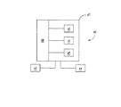
図6は、コンピュータ・システムなど、本発明の実施形態により図3と図4の回路基板アセンブリ30または35の1つまたは複数を含む電子システム40のブロック図である。しかしながら、例示のため、システム40は、回路基板アセンブリ30の1つまたは複数を有するように考察される。システム40は、一般に筐体47内に取り付けられた1つまたは複数の回路基板アセンブリ30を含む電子回路45を含む。そのようなアセンブリ30の1つまたは複数は、一般に、プロセッサ・ユニット41とメモリ42を含む。回路45には、ディスク・ドライブなどの1つまたは複数のデータ記憶装置43、キーボードなどの1つまたは複数の入出力装置44、あるいは表示装置が結合されている。また、周辺装置43、44は、本発明による回路基板アセンブリ30を含むことができる。
FIG. 6 is a block diagram of an
5 ヒートシンク
10 ヒートパイプ
11 フィン
12 基部
13 第2の部分
14 第1の部分
18 フィン
20 電子部品
Claims (9)
少なくとも1つのヒートパイプと、
前記少なくとも1つのヒートパイプが熱発生部品と直接接触するように、前記少なくとも1つのヒートパイプを前記熱発生部品に取り付けるように適合された基部と、
を備えることを特徴とするヒートシンク。 In heat sink of electronic parts,
At least one heat pipe;
A base adapted to attach the at least one heat pipe to the heat generating component such that the at least one heat pipe is in direct contact with the heat generating component;
A heat sink comprising:
前記ヒートシンクの基部を形成するステップと、
ヒートパイプの一部分が前記基部の前記下部から露出して熱発生部品と直接接触するように、前記ヒートパイプを前記基部に取り付けるステップと、
を備えることを特徴とする方法。 In a method of manufacturing a heat sink,
Forming a base of the heat sink;
Attaching the heat pipe to the base such that a portion of the heat pipe is exposed from the lower portion of the base and is in direct contact with the heat generating component;
A method comprising:
Applications Claiming Priority (1)
| Application Number | Priority Date | Filing Date | Title |
|---|---|---|---|
| US10/246,299 US7140422B2 (en) | 2002-09-17 | 2002-09-17 | Heat sink with heat pipe in direct contact with component |
Publications (2)
| Publication Number | Publication Date |
|---|---|
| JP2004111968A true JP2004111968A (en) | 2004-04-08 |
| JP2004111968A5 JP2004111968A5 (en) | 2006-10-19 |
Family
ID=28791705
Family Applications (1)
| Application Number | Title | Priority Date | Filing Date |
|---|---|---|---|
| JP2003319796A Withdrawn JP2004111968A (en) | 2002-09-17 | 2003-09-11 | Heat sink with heat pipe directly brought into contact with component |
Country Status (3)
| Country | Link |
|---|---|
| US (1) | US7140422B2 (en) |
| JP (1) | JP2004111968A (en) |
| GB (1) | GB2393329B (en) |
Families Citing this family (29)
| Publication number | Priority date | Publication date | Assignee | Title |
|---|---|---|---|---|
| US6894900B2 (en) | 2002-09-17 | 2005-05-17 | Hewlett-Packard Development Company, L.P. | Heat sink with heat pipe and base fins |
| US7140422B2 (en) | 2002-09-17 | 2006-11-28 | Hewlett-Packard Development Company, L.P. | Heat sink with heat pipe in direct contact with component |
| TWM244509U (en) * | 2003-07-16 | 2004-09-21 | Hon Hai Prec Ind Co Ltd | A heat pipe radiator |
| TWM243912U (en) * | 2003-08-25 | 2004-09-11 | Tatung Co | Heating dissipating device |
| CN2657082Y (en) * | 2003-10-18 | 2004-11-17 | 鸿富锦精密工业(深圳)有限公司 | Radiator for heat pipe |
| US20060175045A1 (en) * | 2004-03-19 | 2006-08-10 | Yin-Hung Chen | Heat dissipation device |
| CN2696124Y (en) * | 2004-04-22 | 2005-04-27 | 鸿富锦精密工业(深圳)有限公司 | Heat sink |
| CN100338767C (en) * | 2004-05-26 | 2007-09-19 | 鸿富锦精密工业(深圳)有限公司 | Heat pipe radiating unit and manufacturing method thereof |
| US6978828B1 (en) | 2004-06-18 | 2005-12-27 | Schlumberger Technology Corporation | Heat pipe cooling system |
| US7129501B2 (en) * | 2004-06-29 | 2006-10-31 | Sii Nanotechnology Usa, Inc. | Radiation detector system having heat pipe based cooling |
| US20060104032A1 (en) * | 2004-11-16 | 2006-05-18 | Hon Hai Precision Industry Co., Ltd | Heat dissipation device |
| JP4539425B2 (en) * | 2005-04-28 | 2010-09-08 | 日立電線株式会社 | Heat pipe heat sink and method for manufacturing the same |
| CN100456461C (en) * | 2005-06-04 | 2009-01-28 | 富准精密工业(深圳)有限公司 | Heat sink of heat pipe |
| CN101072482A (en) * | 2006-05-12 | 2007-11-14 | 富准精密工业(深圳)有限公司 | Radiating device and radiating system using same |
| US20080115914A1 (en) * | 2006-11-17 | 2008-05-22 | Foxconn Technology Co., Ltd. | Heat dissipation device with heat pipes |
| US7942194B2 (en) * | 2007-04-10 | 2011-05-17 | Fujikura Ltd. | Heat sink |
| US20090059524A1 (en) * | 2007-08-27 | 2009-03-05 | Fu Zhun Precision Industry (Shen Zhen) Co., Ltd. | Heat dissipation device |
| US7770632B2 (en) * | 2007-09-26 | 2010-08-10 | Coolit Systems, Inc. | Thermosiphon for laptop computers comprising a boiling chamber with a square wave partition |
| CN101408301B (en) * | 2007-10-10 | 2012-09-19 | 富准精密工业(深圳)有限公司 | LED light fitting with heat radiating device |
| US7866043B2 (en) * | 2008-04-28 | 2011-01-11 | Golden Sun News Techniques Co., Ltd. | Method of flatting evaporating section of heat pipe embedded in heat dissipation device |
| US8640031B2 (en) * | 2009-09-01 | 2014-01-28 | Samsung Electronics Co., Ltd | Method and apparatus for controlling remote user interface in a home network |
| US8584736B2 (en) * | 2009-11-23 | 2013-11-19 | Fu Zhun Precision Industry (Shen Zhen) Co., Ltd. | Heat sink assembly having a fin also functioning as a supporting bracket |
| CN101764167B (en) * | 2009-12-25 | 2011-08-24 | 赵耀华 | High-efficient solar photovoltaic cell heat dissipating device and electricity and heat cogeneration system |
| TWI465885B (en) * | 2010-01-18 | 2014-12-21 | Furukawa Electric Co Ltd | Heat sink |
| US20110214842A1 (en) * | 2010-03-05 | 2011-09-08 | Lea-Min Technologies Co., Ltd. | Heat sink |
| TWI531303B (en) * | 2011-11-16 | 2016-04-21 | 宏碁股份有限公司 | Heat dissipation module |
| CN104519718A (en) * | 2013-10-08 | 2015-04-15 | 英业达科技有限公司 | Radiating module |
| US20160102920A1 (en) * | 2014-10-08 | 2016-04-14 | Mersen Canada Toronto Inc. | Heat pipe assembly with bonded fins on the baseplate hybrid |
| US20180192545A1 (en) * | 2017-01-03 | 2018-07-05 | Quanta Computer Inc. | Heat dissipation apparatus |
Family Cites Families (39)
| Publication number | Priority date | Publication date | Assignee | Title |
|---|---|---|---|---|
| US4008615A (en) | 1975-04-28 | 1977-02-22 | Emhart Industries, Inc. | Temperature averaging device |
| JPS5742154A (en) | 1980-08-26 | 1982-03-09 | Furukawa Electric Co Ltd:The | Heat pipe type heat sink |
| JPS5833859A (en) | 1981-08-21 | 1983-02-28 | Mitsubishi Electric Corp | Package for semiconductor device |
| JP3020790B2 (en) | 1993-12-28 | 2000-03-15 | 株式会社日立製作所 | Heat pipe type cooling device and vehicle control device using the same |
| JP3094780B2 (en) * | 1994-04-05 | 2000-10-03 | 株式会社日立製作所 | Electronic equipment |
| US5598320A (en) | 1995-03-06 | 1997-01-28 | Ast Research, Inc. | Rotable and slideble heat pipe apparatus for reducing heat build up in electronic devices |
| JPH09126669A (en) | 1995-10-30 | 1997-05-16 | Furukawa Electric Co Ltd:The | Heat pipe type heat sink and electronic component unit |
| JP3106428B2 (en) | 1996-06-12 | 2000-11-06 | 古河電気工業株式会社 | Heat sink and method of manufacturing the same, and electronic device with heat sink and method of manufacturing the same |
| US5699227A (en) | 1996-06-28 | 1997-12-16 | Intel Corporation | Heat pipe to baseplate attachment method |
| US5699853A (en) * | 1996-08-30 | 1997-12-23 | International Business Machines Corporation | Combined heat sink and sink plate |
| US5901040A (en) * | 1997-07-30 | 1999-05-04 | Hewlett-Packard Company | Heat sink and Faraday Cage assembly for a semiconductor module and a power converter |
| JPH1183355A (en) | 1997-09-02 | 1999-03-26 | Furukawa Electric Co Ltd:The | Heat sink with fan |
| JPH11121667A (en) | 1997-10-20 | 1999-04-30 | Fujitsu Ltd | Heat pipe type cooling device |
| JPH11317482A (en) | 1997-12-25 | 1999-11-16 | Furukawa Electric Co Ltd:The | Heat sink |
| FR2773941B1 (en) * | 1998-01-19 | 2000-04-21 | Ferraz | DI-PHASIC EXCHANGER FOR AT LEAST ONE ELECTRONIC POWER COMPONENT |
| DE29806082U1 (en) * | 1998-04-02 | 1998-06-18 | Ideal Electronics Inc., San Chung, Taipei | Cooling device for a central processing unit |
| US6163073A (en) | 1998-04-17 | 2000-12-19 | International Business Machines Corporation | Integrated heatsink and heatpipe |
| JPH11351769A (en) | 1998-06-12 | 1999-12-24 | Furukawa Electric Co Ltd:The | Heat sink |
| JP2000040891A (en) | 1998-07-24 | 2000-02-08 | Fujikura Ltd | Heat sink with heat pipe |
| US6021044A (en) | 1998-08-13 | 2000-02-01 | Data General Corporation | Heatsink assembly |
| US5926370A (en) | 1998-10-29 | 1999-07-20 | Hewlett-Packard Company | Method and apparatus for a modular integrated apparatus for multi-function components |
| US6394175B1 (en) * | 2000-01-13 | 2002-05-28 | Lucent Technologies Inc. | Top mounted cooling device using heat pipes |
| JP4426684B2 (en) | 2000-02-07 | 2010-03-03 | ティーエス ヒートロニクス 株式会社 | heatsink |
| JP2001267772A (en) | 2000-03-15 | 2001-09-28 | Fujitsu Ltd | Heat-radiation structure of electronic part |
| US6377459B1 (en) | 2000-08-04 | 2002-04-23 | Sun Microsystems, Inc. | Chip cooling management |
| JP2002064170A (en) | 2000-08-22 | 2002-02-28 | Fujikura Ltd | Heat sink with plate type heat pipe |
| JP2002151636A (en) | 2000-11-10 | 2002-05-24 | Ts Heatronics Co Ltd | Heat sink |
| JP2002271074A (en) | 2001-03-08 | 2002-09-20 | Toshiba Corp | Cooling device and electronic equipment provided with built-in cooling device |
| US6499894B1 (en) * | 2001-06-28 | 2002-12-31 | Behavior Tech Computer Corporation | Push key with replaceable key cap |
| WO2003041472A1 (en) * | 2001-07-26 | 2003-05-15 | Jefferson Liu | Heat dissipating module |
| US6385044B1 (en) | 2001-07-27 | 2002-05-07 | International Business Machines Corporation | Heat pipe heat sink assembly for cooling semiconductor chips |
| US6830098B1 (en) | 2002-06-14 | 2004-12-14 | Thermal Corp. | Heat pipe fin stack with extruded base |
| US6625021B1 (en) * | 2002-07-22 | 2003-09-23 | Intel Corporation | Heat sink with heat pipes and fan |
| US6785140B2 (en) | 2002-08-28 | 2004-08-31 | Dell Products L.P. | Multiple heat pipe heat sink |
| US6894900B2 (en) | 2002-09-17 | 2005-05-17 | Hewlett-Packard Development Company, L.P. | Heat sink with heat pipe and base fins |
| US7140422B2 (en) | 2002-09-17 | 2006-11-28 | Hewlett-Packard Development Company, L.P. | Heat sink with heat pipe in direct contact with component |
| US6827136B2 (en) | 2002-10-18 | 2004-12-07 | Hon Hai Precision Ind. Co., Ltd. | Heat dissipating apparatus and method for producing same |
| US6796373B1 (en) | 2003-08-27 | 2004-09-28 | Inventec Corporation | Heat sink module |
| US6779595B1 (en) | 2003-09-16 | 2004-08-24 | Cpumate Inc. | Integrated heat dissipation apparatus |
-
2002
- 2002-09-17 US US10/246,299 patent/US7140422B2/en not_active Expired - Fee Related
-
2003
- 2003-08-27 GB GB0320066A patent/GB2393329B/en not_active Expired - Fee Related
- 2003-09-11 JP JP2003319796A patent/JP2004111968A/en not_active Withdrawn
Also Published As
| Publication number | Publication date |
|---|---|
| US20040050534A1 (en) | 2004-03-18 |
| GB0320066D0 (en) | 2003-10-01 |
| GB2393329A (en) | 2004-03-24 |
| GB2393329B (en) | 2006-05-03 |
| US7140422B2 (en) | 2006-11-28 |
Similar Documents
| Publication | Publication Date | Title |
|---|---|---|
| JP2004111968A (en) | Heat sink with heat pipe directly brought into contact with component | |
| JP2004111966A (en) | Heat sink equipped with heat pipe and base fin | |
| JP2004111969A (en) | Heat sink with angled heat pipe | |
| US7028758B2 (en) | Heat dissipating device with heat pipe | |
| US20110232877A1 (en) | Compact vapor chamber and heat-dissipating module having the same | |
| JP2010251756A (en) | Heat dissipation device and method of manufacturing the same | |
| JP5472955B2 (en) | Heat dissipation module | |
| US5725050A (en) | Integrated circuit with taped heat pipe | |
| KR20050081815A (en) | Electronic device equipped with liquid cooling system, and radiator and manufacturing method thereof | |
| US6760222B1 (en) | Dissipating heat using a heat conduit | |
| JP4278720B2 (en) | Plate heat pipe | |
| JP3665508B2 (en) | Heat sink with fins | |
| JPH1183355A (en) | Heat sink with fan | |
| JP2006013217A (en) | Heatsink using carbon graphite | |
| JPH10107192A (en) | Heat sink | |
| KR100488104B1 (en) | Plate Radiator Structure of CPU Cooling Module | |
| US7353862B2 (en) | Liquid cooling device | |
| JP2005259794A (en) | Heatsink for cooling semiconductor element | |
| TWM584082U (en) | Fixing buckle of liquid-cooling heat-dissipation device and its liquid-cooling heat-dissipation module | |
| JP4324364B2 (en) | Heat dissipation device | |
| JP2005093969A (en) | Semiconductor device cooler | |
| JP2000065490A (en) | Plate type heat pipe and cooling structure employing same | |
| JP3217757B2 (en) | Heat sink and cooling structure using it | |
| JP3953211B2 (en) | Heat dissipation structure for electronic elements | |
| JP2007095735A (en) | Cooling device, heat transfer fixing tool and unit cabinet |
Legal Events
| Date | Code | Title | Description |
|---|---|---|---|
| A521 | Request for written amendment filed |
Free format text: JAPANESE INTERMEDIATE CODE: A821 Effective date: 20031219 |
|
| A521 | Request for written amendment filed |
Free format text: JAPANESE INTERMEDIATE CODE: A523 Effective date: 20060901 |
|
| A621 | Written request for application examination |
Free format text: JAPANESE INTERMEDIATE CODE: A621 Effective date: 20060901 |
|
| A761 | Written withdrawal of application |
Free format text: JAPANESE INTERMEDIATE CODE: A761 Effective date: 20080327 |