JP2004106918A - Paper overcap - Google Patents
Paper overcap Download PDFInfo
- Publication number
- JP2004106918A JP2004106918A JP2002275077A JP2002275077A JP2004106918A JP 2004106918 A JP2004106918 A JP 2004106918A JP 2002275077 A JP2002275077 A JP 2002275077A JP 2002275077 A JP2002275077 A JP 2002275077A JP 2004106918 A JP2004106918 A JP 2004106918A
- Authority
- JP
- Japan
- Prior art keywords
- paper
- overcap
- side wall
- wall portion
- range
- Prior art date
- Legal status (The legal status is an assumption and is not a legal conclusion. Google has not performed a legal analysis and makes no representation as to the accuracy of the status listed.)
- Pending
Links
Images

Landscapes
- Closures For Containers (AREA)
Abstract
【課題】紙カップに被せるオーバーキャップであって、環境対応の点で問題のない紙を材料として、紙カップに確実に嵌合することができ、材料コストおよび加工コストが安い紙製オーバーキャップを提供することにある。
【解決手段】本発明は、紙カップに被せる天部と側壁部とからなるオーバーキャップであって、一枚のブランクから深絞りで成形され、使用する材料が紙又は紙を主体とする積層体からなり、前記紙の坪量が50〜300g/m2の範囲であり、湿度65%の環境下での前記紙の破断伸びが縦方向で10%以上、横方向で10%以上であることを特徴とする紙製オーバーキャップである。
【選択図】図2Provided is an overcap that can be securely fitted to a paper cup using paper that is not problematic in terms of environmental friendliness and that is low in material cost and processing cost. It is in.
The present invention relates to an overcap comprising a top portion and a side wall portion to be placed on a paper cup, which is formed by deep drawing from one blank, and the material to be used is a paper or a laminate mainly composed of paper. Wherein the basis weight of the paper is in the range of 50 to 300 g / m 2 and the breaking elongation of the paper in an environment of 65% humidity is 10% or more in the machine direction and 10% or more in the transverse direction. Characteristic paper overcap.
[Selection diagram] FIG.
Description
【0001】
【発明の属する技術分野】
本発明は、紙カップに被せる紙製オーバーキャップに関するものであり、詳しくは、一枚の紙ブランクを深絞りして作製した紙製オーバーキャップに関するものである。
【0002】
【従来の技術】
従来より、自動販売機などで飲料用、即席食品用などに紙カップが広く使用されている。また、アイスクリーム、ヨーグルトなどの容器としても広く使用されている。この紙カップPは、図8に示すように、胴部材10と底部材20とからなり、胴部材10は主に胴部11を形成し、上端を外側にカールしてトップカール部12(あるいはトップカール部を潰して形成したフランジ部)とし、下端を内側に折り返して折り返し部13としている。一方、底部材20は主に底面部21を形成し、外周縁部を下方へ略直角に屈曲して屈曲部22としている。胴部材10と底部材20の接合は、底部材20の屈曲部22を、胴部材10の折り返し部13と、胴部11の下端部とで挟んで加熱圧着している。さらに、胴部11の内面上部には、注ぎ込む内容物の上端を指示するために、全周に渡って凹部14が設けられている形状のものもある。
【0003】
また、この紙カップPに被せる蓋としては、切断したスパイラル管などからなる側板の上端部分を内側に巻き込むなどし、その部分に円形の天板の周縁部を固定した形状のもの(例えば、特許文献1。)。あるいは、プラスチックの成形によるオーバーキャップが使用されている(例えば、非特許文献2。)。
【0004】
【非特許文献1】
実開平6−25107号公報(第3頁、第4図)
【非特許文献2】
特開平8−119252号公報(第5頁、第1図)
【0005】
【発明が解決しようとする課題】
しかしながら、前者のスパイラル管による蓋は、被せた蓋が脱着しやすく、また、紙カップPとの間に間隙ができ、外から異物が侵入するという危険性があり、また、材料コストおよび加工コストが高いという問題がある。一方、後者のプラスチックの成形によるオーバーキャップは、コスト的には利点があるものの、廃棄する時に、分別して捨てる必要があるなど、環境対応の点で問題がある。
【0006】
本発明は、紙カップに被せるオーバーキャップであって、環境対応の点で問題のない紙を材料として、紙カップに確実に嵌合することができ、材料コストおよび加工コストが安い紙製オーバーキャップを提供することを目的とするものである。
【0007】
【課題を解決するための手段】
上記のような課題を解決すべく検討した結果、本発明の紙製オーバーキャップは、胴部材と底部材とが互いに接合され、前記胴部材の胴部の上端にトップカール部又は該トップカール部を潰したフランジ部が形成された紙カップに被せる天部と側壁部とからなるオーバーキャップであって、一枚のブランクから深絞りで成形され、使用する材料が紙又は紙を主体とする積層体からなり、前記紙の坪量が50〜300g/m2の範囲であり、湿度65%の環境下での前記紙の破断伸びが縦方向で10%以上、横方向で10%以上であることを特徴とする紙製オーバーキャップである。
【0008】
具体的な形状としては、一つとしては、前記天部と前記側壁部との角度を90〜120度の範囲とし、前記側壁部の内面に全周に渡って側壁凹部を形成したことを特徴とする紙製オーバーキャップであり、前記天部の全部又は一部に内側方向(下方向)に凹状に成形した天凹部を形成することもできるものである。もう一つとしては、前記天部と前記側壁部との角度を90〜120度の範囲とし、前記側壁部の下端部を内側に巻き込んで内カール部を形成したことを特徴とする紙製オーバーキャップである。
【0009】
さらに、本発明の別の形状としては、胴部材と底部材とが互いに接合され、前記胴部材の胴部の内面上部に凹部が全周に渡って形成された紙カップの内側に嵌め込む天部と側壁部とからなるオーバーキャップであって、一枚のブランクから深絞りで成形され、使用する材料が紙又は紙を主体とする積層体からなり、前記紙の坪量が50〜300g/m2の範囲であり、湿度65%の環境下での前記紙の破断伸びが縦方向で10%以上、横方向で10%以上であり、前記天部と前記側壁部との角度を90〜120度の範囲とし、前記側壁部の下端部を外側に巻き込んで外カール部を形成したことを特徴とする紙製オーバーキャップである。
【0010】
本発明によれば、紙カップに被せる蓋であって、材料として、坪量が50〜300g/m2の範囲であり、湿度65%の環境下での破断伸びが縦方向で10%以上、横方向で10%以上である紙を主体とする積層体を使用し、一枚のブランクから成形して急角度で深い凹状に形成することにより、環境対応の点で問題がなく、紙カップに確実に嵌合することができ、材料コストおよび加工コストが安い紙製オーバーキャップを得ることができるものである。
【0011】
【発明の実施の形態】
以下に、図面を参照しながら、本発明の実施の形態について、実施例をあげてさらに詳しく説明する。
【0012】
図1は、本発明による紙製オーバーキャップの第一の実施の形態の一実施例の断面図および紙カップPに被せた状態を示す一部切り欠け平面図である。この紙製オーバーキャップAは、一枚の平らな紙を天部1と側壁部2とからなる形状に成形したものである。この天部1と側壁部2とがなす角度Qを90〜120度の範囲としている。この角度Qが90度に近くなる程、紙カップPに被せた時に、紙カップPから脱着しにくくなる。
【0013】
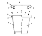
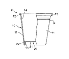
図2は、本発明による紙製オーバーキャップの第二の実施の形態の一実施例の断面図および紙カップPに被せた状態を示す一部切り欠け平面図である。この紙製オーバーキャップBは、一枚の平らな紙を天部1と側壁部2とからなる形状に成形したものである。この天部1と側壁部2とがなす角度Qも90〜120度の範囲としているが、90度に近くなる程、紙カップPに被せた時に、紙カップPから脱着しにくくなる。また、この紙製オーバーキャップBを紙カップPに被せた時に、紙カップPのトップカール部12に嵌合するように、側壁部2の内側に全周に渡って側壁凹部2aが設けられている。側壁凹部2aを設けていることにより、紙カップPに被せた時に、紙カップPのトップカール部12が紙製オーバーキャップBの側壁部2の側壁凹部2aに嵌合して脱着しにくくなっている。この側壁凹部2aの形状は、略半円形とし、紙カップのトップカール部12を嵌合することができるように適宜設定する。
【0014】
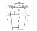
図3は、本発明による紙製オーバーキャップの第三の実施の形態の一実施例の断面図および紙カップPに被せた状態を示す一部切り欠け平面図である。この紙製オーバーキャップCは、第二の実施の形態と同様に、この紙製オーバーキャップCを紙カップPに被せた時に、紙カップPのトップカール部12に嵌合するように、側壁部2の内側に全周に渡って側壁凹部2aが設けられ、さらに、天部1を内側方向(下方向)に凹状に成形して天凹部1aが形成され、落とし蓋の形状としている。この天凹部1aは、図3に示すように、天部1全体を凹状に成形してもよいが、天部1の一部を凹状に成形してもよい。また、天凹部1aの深さ、底面1a1と側壁面1a2との角度Rは、特に、限定されるものではない。
【0015】
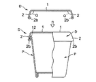
図4は、本発明による紙製オーバーキャップの第四の実施の形態の一実施例の断面図および紙カップPに被せた状態を示す一部切り欠け平面図である。この紙製オーバーキャップDは、一枚の平らな紙を天部1と側壁部2とからなる形状に成形したものである。この天部1と側壁部2とがなす角度Qを90〜120度の範囲としている。好ましくは、90〜105度の範囲である。また、この紙製オーバーキャップDを紙カップPに被せた時に、紙カップPのトップカール部12に係合するように、側壁部2の下端を内側に巻き込んだ内カール部2bが設けられている。この内カール部2bを設けていることにより、紙製オーバーキャップDを紙カップPに被せた時に、紙カップPのトップカール部12と紙製オーバーキャップDの側壁部2に設けた内カール部2bとが係合しあい脱着しにくくなっている。
【0016】
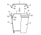
図5は、本発明による紙製オーバーキャップの第五の実施の形態の一実施例の断面図および紙カップPに被せた状態を示す一部切り欠け平面図である。この紙製オーバーキャップEは、一枚の平らな紙を天部1と側壁部2とからなる形状に成形したものである。この天部1と側壁部2とがなす角度Qを90〜120度の範囲としている。好ましくは90〜105度の範囲である。また、この紙製オーバーキャップEは、紙カップPに被せるのではなく、紙カップPの内側上部に嵌め込む形態である。そして、この紙製オーバーキャップEを紙カップPの内側上部に嵌め込んだ時に、紙カップPの内面上部に設けられている凹部14に嵌合するように、側壁部2の下端を外側に巻き込んだ外カール部2cが設けられている。この外カール部2cを設けていることにより、紙製オーバーキャップEを紙カップPの内側に嵌め込んだ時に、紙製オーバーキャップEの側壁部2の下端の外カール部2cが紙カップPの内面上部に設けられた凹部14に嵌合して脱着しにくくなっている。
【0017】
また、それぞれの実施の形態において、天部1に窓を設けて透明プラスチックフィルムを貼り合せて内容物を外から透視できる形状とすることができる。
【0018】
また、本発明の紙製オーバーキャップと紙カップPとを一部分で接着するか、あるいは、粘着テープ、ステッチャーなどで一部分を固定することによって、開閉が自在な形状とすることができる。
【0019】
上記の本発明の紙製オーバーキャップにおいては、天部1と側壁部2との角度Qを90〜120度の範囲、特に90度に近い急角度の凹凸状に変形する時、変形しやすく、かつ、ひび割れやピンホールが生じない材料を使用することを特徴としている。すなわち、坪量が50〜300g/m2の範囲であり、湿度65%の環境下での破断伸びが縦方向で10%以上、横方向で10%以上、好ましくは縦方向で15%以上、横方向で15%以上である紙を使用する。この条件の紙を成形することにより、雄型と雌型で構成されたプレス成形機により容易に深い凹状に成形することができ、かつ、絞り皺や亀裂のない紙製オーバーキャップを得ることができる。この紙の坪量が50g/m2未満であると、剛性が不足するとともに、ピンホールが発生しやすくなり好ましくない。また、この紙の坪量が300g/m2を超えると、プレス成形機の成形負荷が大きくなり好ましくない。また、破断伸びが縦方向で10%未満、横方向で10%未満の場合には、十分深い凹状に成形することができないばかりか、成形時に亀裂などの不具合が発生し、好ましくない。
【0020】
また、本発明の紙製オーバーキャップに使用する材料は、紙単体でもよいが、紙を主体とする積層体とすることができる。その積層体は、内面または内外両面に熱可塑性樹脂層を設けることを基本としている。
【0021】
最内層および最外層に使用する熱可塑性樹脂は、内容物の保護、あるいは、外側からの汚染などを防ぐ機能を持っている必要がある。具体的には、ポリエチレン、ポリプロピレン、ポリエステル、ナイロン、エチレンビニルアルコール、エチレン−酢酸ビニル共重合体などが挙げられる。厚さとしては、15〜60μmの範囲が好ましい。これらの熱可塑性樹脂は、押し出し加工あるいはラミネート加工によって、最内層および最外層に形成される。
【0022】
例えば、具体的な材料の構成としては、表面側から紙層/ポリエチレン樹脂層、ポリエチレン樹脂層/紙層/ポリエチレン樹脂層、発泡ポリエチレン樹脂層/紙層/ポリエチレン樹脂層、紙層/ポリプロピレン樹脂層、ポリプロピレン樹脂層/紙層/ポリプロピレン樹脂層、紙層/ポリエステル樹脂層、ポリエステル樹脂層/紙層/ポリエステル樹脂層、紙層/ナイロン樹脂層、ナイロン樹脂層/紙層/ナイロン層などが挙げられる。
【0023】
また、本発明の紙製オーバーキャップを被せる紙カップは、一般的な紙カップであり、特に限定されるものではないが、材料として、紙カップ成形適性の良い一般的なカップ原紙を主体とした積層体を使用することが好ましい。坪量は、とくに限定されないが、紙カップ成形適性上、150〜300g/m2の範囲がより好ましい。
【0024】
つぎに、本発明の紙製オーバーキャップを製造する方法について概略を説明する。
【0025】
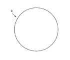
まず、前述の条件を有する紙またはその紙を主体とする積層体を使用して、図6に示すような円形のブランク3を打ち抜き加工で作製する。
【0026】
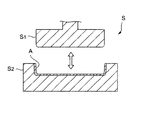
つぎに、図7に示すように、雄型s1と雌型s2で構成されたプレス成形機Sによる深絞り成形加工行い、天部1と側壁部2との角度が略90度の急角度で深く成形された紙製オーバーキャップAを作製する。この成形加工では、熱を加えることにより、さらに、成形を良くすることができる。
【0027】
さらに、つぎの工程で、紙製オーバーキャップBの場合には、側壁部2の内面にプレス加工で側壁凹部2aを形成する。また、紙製オーバーキャップCの場合には、側壁部2の内面にプレス加工で側壁凹部2aを形成した上に、天部1を内側方向(下方向)に凹状に成形して天凹部1aを形成する。さらに、紙製オーバーキャップDあるいはEの場合には、側壁部2の下端を内側に巻き込む加工を行ない内カール部2bあるいは外カール部2cを形成する。
【0028】
また、前述の窓を設ける場合には、ブランク3の状態、あるいは、成形加工後に打ち抜き加工で窓を設け、その窓を覆って透明プラスチックフィルムを貼り合わせて形成する方法と、紙を主体とする積層体を作製する工程で、あらかじめ窓を抜いておいた紙に透明プラスチックフィルムを全面に貼り合わせて積層体とし、その積層体をブランク3に打ち抜いて成形加工して形成する方法がある。
【0029】
本発明の紙製オーバーキャップの用途は、自動販売機などで飲料用、即席食品用などに紙カップ用として広く使用することができる。また、アイスクリーム、ヨーグルトなどの紙カップ用としても広く使用することができる。
【0030】
【実施例】
つぎに、本発明の紙製オーバーキャップについて実施例をあげて、さらに具体的に説明する。なお、本発明はこれによって限定されるものではない。
【0031】
〔実施例〕
材料として、表面から特殊成形紙(商品名:NPiモールドペーパーグレード「MP275」(日本製紙(株)製))275g/m2/低密度ポリエチレン樹脂25μmの構成の材料を使用し、胴部材1の材料として、表面からカップ原紙280g/m2/低密度ポリエチレン樹脂25μmの構成の材料を使用した。
【0032】
まず、図6のような円形のブランク3に打ち抜き、このブランク3を、雄型s1と雌型s2で構成されたプレス成形機Sにより、熱圧して天部1と側壁部2との角度Qが略90度となる形状に成形して紙製オーバーキャップAを作成した。つぎに、側壁部2の内面の中央部に全周に渡って側壁凹部2aをプレス加工で形成して紙製オーバーキャップBを作製した。材料として、破断伸びが縦方向で22.5%、横方向で13.2%である特殊成形紙を使用したことによって、天部1と側壁部2との角度Qを略90度の急角度で深い凹状とすることができたと同時に、成形時に亀裂などが入ることがなかった。
【0033】
【発明の効果】
以上説明したように、本発明の紙製オーバーキャップは、天部と側壁部とからなり、一枚のブランクから成形され、材料として、坪量が50〜300g/m2の範囲であり、湿度65%の環境下での破断伸びが縦方向で10%以上、横方向で10%以上である紙を使用することにより、容易に天部と側壁部との角度を90〜120度の範囲、特に90度に近い急角度で深い凹状に成形することができ、かつ、亀裂などが入らない状態で成形することができるという効果を有している。また、この紙製オーバーキャップは、環境対応の点で問題がなく、紙カップに確実に嵌合することができ、材料コストおよび加工コストが安いという効果も有している。
【図面の簡単な説明】
【図1】本発明による紙製オーバーキャップの第一の実施の形態の一実施例の断面図および紙カップに被せた状態を示す部分切り欠け平面図である。
【図2】本発明による紙製オーバーキャップの第二の実施の形態の一実施例の断面図および紙カップに被せた状態を示す部分切り欠け平面図である。
【図3】本発明による紙製オーバーキャップの第三の実施の形態の一実施例の断面図および紙カップに被せた状態を示す部分切り欠け平面図である。
【図4】本発明による紙製オーバーキャップの第四の実施の形態の一実施例の断面図および紙カップに被せた状態を示す部分切り欠け平面図である。
【図5】本発明による紙製オーバーキャップの第五の実施の形態の一実施例の断面図および紙カップに被せた状態を示す部分切り欠け平面図である。
【図6】本発明による紙製オーバーキャップの成形前のブランクを示す展開図である。
【図7】本発明による紙製オーバーキャップを製造する方法を説明する概略図である。
【図8】従来の紙カップを示す部分切り欠け平面図である。
【符号の説明】
A 紙製オーバーキャップ(第一の実施の形態)
B 紙製オーバーキャップ(第二の実施の形態)
C 紙製オーバーキャップ(第三の実施の形態)
D 紙製オーバーキャップ(第四の実施の形態)
E 紙製オーバーキャップ(第五の実施の形態)
P 紙カップ
Q 角度(紙製オーバーキャップの天部と側壁部)
R 角度(天凹部の底面と側壁面)
1 天部
1a 天凹部
1a1 底面
1a2 側壁面
2 側壁部
2a 側壁凹部
2b 内カール部
2c 外カール部
3 ブランク
10 胴部材
11 胴部
12 トップカール部
13 折り返し部
14 凹部
20 底部材
21 底面部
22 屈曲部[0001]
TECHNICAL FIELD OF THE INVENTION
The present invention relates to a paper overcap to be placed on a paper cup, and more particularly, to a paper overcap produced by deep drawing one paper blank.
[0002]
[Prior art]
BACKGROUND ART Conventionally, paper cups have been widely used for beverages, instant foods, and the like in vending machines and the like. It is also widely used as a container for ice cream, yogurt and the like. As shown in FIG. 8, the paper cup P includes a
[0003]
Further, as a lid to be put on the paper cup P, an upper end portion of a side plate made of a cut spiral tube or the like is wound inward, and a peripheral portion of a circular top plate is fixed to the portion (for example, see Patent Document 1). 1). Alternatively, an overcap formed by molding plastic is used (for example, Non-Patent Document 2).
[0004]
[Non-patent document 1]
Japanese Utility Model Laid-Open No. 6-25107 (
[Non-patent document 2]
JP-A-8-119252 (page 5, FIG. 1)
[0005]
[Problems to be solved by the invention]
However, in the case of the former lid made of a spiral tube, the lid that is put on is easily detachable, a gap is formed between the lid and the paper cup P, and there is a risk that foreign matter may enter from outside. There is a problem of high. On the other hand, the latter overcap formed by molding plastic has an advantage in terms of cost, but has a problem in terms of environmental measures such as the necessity of separating and discarding when discarding.
[0006]
The present invention provides a paper overcap that can be securely fitted to a paper cup using paper that is not problematic in terms of environmental friendliness and that is low in material cost and processing cost. It is intended to do so.
[0007]
[Means for Solving the Problems]
As a result of studying to solve the above problems, the paper overcap of the present invention has a trunk member and a bottom member joined to each other, and a top curl portion or the top curl portion is formed at an upper end of a trunk portion of the trunk member. An overcap consisting of a top part and a side wall part which are put on a paper cup having a flange part formed by crushing the sheet, and formed by deep drawing from one blank, and the material to be used is paper or a laminate mainly composed of paper. Wherein the basis weight of the paper is in the range of 50 to 300 g / m 2 , and the elongation at break of the paper in an environment of 65% humidity is 10% or more in the machine direction and 10% or more in the transverse direction. This is a paper overcap characterized by the following.
[0008]
As a specific shape, one feature is that an angle between the top portion and the side wall portion is in a range of 90 to 120 degrees, and a side wall recess is formed on the inner surface of the side wall portion over the entire circumference. It is also possible to form a ceiling recess formed in an inward (downward) shape on the whole or a part of the ceiling portion. Another feature is that an angle between the top portion and the side wall portion is in a range of 90 to 120 degrees, and a lower end portion of the side wall portion is wound inward to form an inner curl portion. Cap.
[0009]
Further, as another shape of the present invention, a top part is fitted into the inside of a paper cup in which a body member and a bottom member are joined to each other, and a concave portion is formed over the entire inner surface of the body part of the body member. And a side wall portion, which is formed by deep drawing from one blank, the material to be used is paper or a laminate mainly composed of paper, and the basis weight of the paper is 50 to 300 g / m. 2, the elongation at break of the paper in an environment of 65% humidity is 10% or more in the vertical direction and 10% or more in the horizontal direction, and the angle between the top portion and the side wall portion is 90 to 120. A paper overcap, wherein the outer curl portion is formed by winding the lower end portion of the side wall portion outwardly in a range of degrees.
[0010]
According to the present invention, a lid to be placed on a paper cup, having a basis weight in a range of 50 to 300 g / m 2 and a breaking elongation of 10% or more in a longitudinal direction under an environment of 65% humidity, By using a laminated body mainly composed of paper that is 10% or more in the direction and forming it from a single blank to form a deep concave at a steep angle, there is no problem in terms of environmental compatibility, and the paper cup is securely attached. It is possible to obtain a paper overcap that can be fitted and has low material and processing costs.
[0011]
BEST MODE FOR CARRYING OUT THE INVENTION
Hereinafter, embodiments of the present invention will be described in more detail with reference to the drawings.
[0012]
FIG. 1 is a cross-sectional view of an example of a paper overcap according to the first embodiment of the present invention, and a partially cutaway plan view showing a state where the paper overcap is put on a paper cup P. The paper overcap A is formed by molding a single piece of flat paper into a shape including a
[0013]
FIG. 2 is a cross-sectional view of an example of the second embodiment of the paper overcap according to the present invention and a partially cutaway plan view showing a state where the paper overcap is put on a paper cup P. The paper overcap B is formed by molding a single piece of flat paper into a shape including a
[0014]
FIG. 3 is a cross-sectional view of an example of a third embodiment of a paper overcap according to the present invention and a partially cutaway plan view showing a state where the paper overcap is placed on a paper cup P. As in the second embodiment, when the paper overcap C is put on the paper cup P, the paper overcap C is fitted to the
[0015]
FIG. 4 is a sectional view of an example of a fourth embodiment of a paper overcap according to the present invention and a partially cutaway plan view showing a state where the paper overcap is placed on a paper cup P. The paper overcap D is formed by molding a single piece of flat paper into a shape including a
[0016]
FIG. 5 is a cross-sectional view of an example of a fifth embodiment of a paper overcap according to the present invention, and a partially cutaway plan view showing a state where the paper overcap is placed on a paper cup P. The paper overcap E is formed by molding a single piece of flat paper into a shape including a
[0017]
Further, in each embodiment, a window can be provided in the
[0018]
Also, the paper overcap of the present invention and the paper cup P are partially adhered to each other or partially fixed with an adhesive tape, a stitcher, or the like, so that the shape can be freely opened and closed.
[0019]
In the above-mentioned paper overcap of the present invention, when the angle Q between the
[0020]
Further, the material used for the paper overcap of the present invention may be paper alone, but may be a laminate mainly composed of paper. The laminate is basically provided with a thermoplastic resin layer on the inner surface or both inner and outer surfaces.
[0021]
The thermoplastic resin used for the innermost layer and the outermost layer needs to have a function of protecting the contents or preventing contamination from the outside. Specific examples include polyethylene, polypropylene, polyester, nylon, ethylene vinyl alcohol, and ethylene-vinyl acetate copolymer. The thickness is preferably in the range of 15 to 60 μm. These thermoplastic resins are formed in the innermost layer and the outermost layer by extrusion or lamination.
[0022]
For example, specific material configurations include a paper layer / polyethylene resin layer, a polyethylene resin layer / paper layer / polyethylene resin layer, a foamed polyethylene resin layer / paper layer / polyethylene resin layer, and a paper layer / polypropylene resin layer from the surface side. , Polypropylene resin layer / paper layer / polypropylene resin layer, paper layer / polyester resin layer, polyester resin layer / paper layer / polyester resin layer, paper layer / nylon resin layer, nylon resin layer / paper layer / nylon layer, and the like. .
[0023]
Further, the paper cup to be covered with the paper overcap of the present invention is a general paper cup, and is not particularly limited, but as a material, a laminate mainly composed of a general cup base paper having good suitability for paper cup molding is used. It is preferred to use. The basis weight is not particularly limited, but is more preferably in the range of 150 to 300 g / m 2 in terms of suitability for forming a paper cup.
[0024]
Next, an outline of a method for manufacturing the paper overcap of the present invention will be described.
[0025]
First, a circular blank 3 as shown in FIG. 6 is manufactured by punching using paper having the above-described conditions or a laminate mainly including the paper.
[0026]
Next, as shown in FIG. 7, deep drawing is performed by a press forming machine S composed of a male mold s1 and a female mold s2, and the angle between the
[0027]
Further, in the next step, in the case of the paper overcap B, a
[0028]
In the case of providing the above-mentioned window, a method of forming a window by punching after the state of the blank 3 or the molding process and covering the window with a transparent plastic film, and mainly using paper. In the step of producing a laminate, there is a method in which a transparent plastic film is pasted on the entire surface of paper from which a window has been previously removed to form a laminate, and the laminate is punched into a blank 3 and formed by forming.
[0029]
The use of the paper overcap of the present invention can be widely used as a paper cup for drinks, instant foods and the like in vending machines and the like. It can also be widely used for paper cups such as ice cream and yogurt.
[0030]
【Example】
Next, the paper overcap of the present invention will be described more specifically by way of examples. The present invention is not limited by this.
[0031]
〔Example〕
As the material, a special molded paper (product name: NPi molded paper grade “MP275” (manufactured by Nippon Paper Industries Co., Ltd.)) 275 g / m 2 / low-density polyethylene resin 25 μm is used for the
[0032]
First, the blank 3 is punched into a circular blank 3 as shown in FIG. 6, and the blank 3 is hot-pressed by a press forming machine S composed of a male mold s1 and a female mold s2 to form an angle Q between the
[0033]
【The invention's effect】
As described above, the paper overcap of the present invention includes a top portion and a side wall portion, is formed from one blank, has a basis weight in the range of 50 to 300 g / m 2 as a material, and has a humidity By using paper whose elongation at break in an environment of 65% is 10% or more in the vertical direction and 10% or more in the horizontal direction, the angle between the top portion and the side wall portion can be easily set in the range of 90 to 120 degrees. In particular, it has an effect that it can be formed into a deep concave shape at a steep angle close to 90 degrees and can be formed without cracks or the like. In addition, the paper overcap has no problem in terms of environmental friendliness, can be securely fitted to a paper cup, and has the effect of reducing material costs and processing costs.
[Brief description of the drawings]
FIG. 1 is a cross-sectional view of an example of a first embodiment of a paper overcap according to the present invention and a partially cutaway plan view showing a state where the paper overcap is placed on a paper cup.
FIG. 2 is a cross-sectional view of an example of a second embodiment of a paper overcap according to the present invention and a partially cutaway plan view showing a state where the paper overcap is put on a paper cup.
FIG. 3 is a cross-sectional view of an example of a third embodiment of a paper overcap according to the present invention and a partially cutaway plan view showing a state where the overcap is placed on a paper cup.
FIG. 4 is a sectional view of an example of a fourth embodiment of a paper overcap according to the present invention and a partially cutaway plan view showing a state where the paper overcap is placed on a paper cup.
FIG. 5 is a cross-sectional view of an example of a fifth embodiment of a paper overcap according to the present invention and a partially cutaway plan view showing a state where the paper overcap is put on a paper cup.
FIG. 6 is a development view showing a blank before forming the paper overcap according to the present invention.
FIG. 7 is a schematic view illustrating a method of manufacturing a paper overcap according to the present invention.
FIG. 8 is a partially cutaway plan view showing a conventional paper cup.
[Explanation of symbols]
A paper overcap (first embodiment)
B. Paper overcap (second embodiment)
C paper overcap (third embodiment)
D Paper Overcap (Fourth Embodiment)
E Paper overcap (fifth embodiment)
P Paper cup Q angle (top and side wall of paper overcap)
R angle (bottom surface and side wall surface of ceiling recess)
1
Claims (5)
Priority Applications (1)
| Application Number | Priority Date | Filing Date | Title |
|---|---|---|---|
| JP2002275077A JP2004106918A (en) | 2002-09-20 | 2002-09-20 | Paper overcap |
Applications Claiming Priority (1)
| Application Number | Priority Date | Filing Date | Title |
|---|---|---|---|
| JP2002275077A JP2004106918A (en) | 2002-09-20 | 2002-09-20 | Paper overcap |
Publications (1)
| Publication Number | Publication Date |
|---|---|
| JP2004106918A true JP2004106918A (en) | 2004-04-08 |
Family
ID=32271377
Family Applications (1)
| Application Number | Title | Priority Date | Filing Date |
|---|---|---|---|
| JP2002275077A Pending JP2004106918A (en) | 2002-09-20 | 2002-09-20 | Paper overcap |
Country Status (1)
| Country | Link |
|---|---|
| JP (1) | JP2004106918A (en) |
Cited By (10)
| Publication number | Priority date | Publication date | Assignee | Title |
|---|---|---|---|---|
| JP2006224979A (en) * | 2005-02-16 | 2006-08-31 | Chuo Kagaku Co Ltd | Packaging container |
| JP2016504243A (en) * | 2013-01-28 | 2016-02-12 | ニュー ヒップリック パッケイジング プロダクツ (シェンジェン) カンパニー リミテッド | Flexible plastic packaging box |
| JP2017513781A (en) * | 2014-04-15 | 2017-06-01 | 丹東銘程環保製品股▲ふん▼有限公司 | Press molded cup lid outer cover edge manufacturing method and finished product |
| US10582787B2 (en) | 2012-08-22 | 2020-03-10 | Ptm Packaging Tools Machinery Pte. Ltd. | Paper-based container lids and methods for making the same |
| WO2020049769A1 (en) * | 2018-09-04 | 2020-03-12 | 東罐興業株式会社 | Paper lid |
| KR20200113753A (en) * | 2019-03-26 | 2020-10-07 | 강승대 | Method of manufacture of cup caps and their for takeout |
| JP2022055259A (en) * | 2020-09-28 | 2022-04-07 | 株式会社Ky7 | Lid body and method of manufacturing lid body |
| US11691373B2 (en) | 2018-08-30 | 2023-07-04 | Tokan Kogyo Co., Ltd. | Paper lid production method |
| DE102022130532A1 (en) * | 2022-11-18 | 2024-05-23 | Krones Aktiengesellschaft | Method for producing a container comprising fibres and device for carrying out the method |
| JP2024120000A (en) * | 2020-10-23 | 2024-09-03 | 株式会社Ky7 | Lid and method for manufacturing the lid |
-
2002
- 2002-09-20 JP JP2002275077A patent/JP2004106918A/en active Pending
Cited By (15)
| Publication number | Priority date | Publication date | Assignee | Title |
|---|---|---|---|---|
| JP2006224979A (en) * | 2005-02-16 | 2006-08-31 | Chuo Kagaku Co Ltd | Packaging container |
| US11497330B2 (en) | 2012-08-22 | 2022-11-15 | Ptm Packaging Tools Machinery Pte. Ltd. | Paper-based container lids and methods for making the same |
| US10582787B2 (en) | 2012-08-22 | 2020-03-10 | Ptm Packaging Tools Machinery Pte. Ltd. | Paper-based container lids and methods for making the same |
| JP2016504243A (en) * | 2013-01-28 | 2016-02-12 | ニュー ヒップリック パッケイジング プロダクツ (シェンジェン) カンパニー リミテッド | Flexible plastic packaging box |
| JP2017513781A (en) * | 2014-04-15 | 2017-06-01 | 丹東銘程環保製品股▲ふん▼有限公司 | Press molded cup lid outer cover edge manufacturing method and finished product |
| US11691373B2 (en) | 2018-08-30 | 2023-07-04 | Tokan Kogyo Co., Ltd. | Paper lid production method |
| WO2020049769A1 (en) * | 2018-09-04 | 2020-03-12 | 東罐興業株式会社 | Paper lid |
| JPWO2020049769A1 (en) * | 2018-09-04 | 2021-02-15 | 東罐興業株式会社 | Paper lid |
| US11572220B2 (en) | 2018-09-04 | 2023-02-07 | Tokan Kogyo Co., Ltd. | Paper lid |
| KR20200113753A (en) * | 2019-03-26 | 2020-10-07 | 강승대 | Method of manufacture of cup caps and their for takeout |
| KR102181484B1 (en) | 2019-03-26 | 2020-11-23 | 강승대 | Method of manufacture of cup caps and their for takeout |
| JP2022055259A (en) * | 2020-09-28 | 2022-04-07 | 株式会社Ky7 | Lid body and method of manufacturing lid body |
| JP2024120000A (en) * | 2020-10-23 | 2024-09-03 | 株式会社Ky7 | Lid and method for manufacturing the lid |
| JP7788091B2 (en) | 2020-10-23 | 2025-12-18 | 株式会社Ky7 | Lid and method for manufacturing the lid |
| DE102022130532A1 (en) * | 2022-11-18 | 2024-05-23 | Krones Aktiengesellschaft | Method for producing a container comprising fibres and device for carrying out the method |
Similar Documents
| Publication | Publication Date | Title |
|---|---|---|
| US20260054879A1 (en) | Container with paperboard outer layer and thin plastic foil inner layer | |
| JP2004106918A (en) | Paper overcap | |
| JP2014037265A (en) | Paper cup container | |
| WO2007110897A1 (en) | Paper-made lid for paper-made container | |
| JP3953992B2 (en) | Insulating paper container | |
| CN114030762A (en) | The sealing structure of the packaging box, the production process of the sealing structure and the packaging box | |
| JP2003341649A (en) | Deformed bottom paper cup | |
| JP4358004B2 (en) | Insulated composite container | |
| JP3967129B2 (en) | Insulated paper container | |
| JPWO2017029997A1 (en) | Paper container and manufacturing method thereof | |
| CN216233879U (en) | Sealing structure of packing box and packing box | |
| JP2000118590A (en) | Ice cream containers | |
| JP3075141B2 (en) | Insulated cup | |
| JP2000344281A (en) | Insulated container | |
| JP4580500B2 (en) | Square paper cup | |
| EP1347924B1 (en) | Folded package and method of making such a package | |
| JPH0952300A (en) | Material for container and container made of the material | |
| JP2009202891A (en) | Double container | |
| JP2949149B2 (en) | Aluminum laminated wood | |
| JP2003128104A (en) | Polygon cover made of paper | |
| JPH0648436A (en) | Beverage container | |
| JP2003191941A (en) | Paper cup with sealed lid | |
| JP2004001822A (en) | Draw-formed container and method for producing the same | |
| JP2003341648A (en) | Deformed bottom paper cup | |
| JP4478287B2 (en) | Cup-shaped container |
Legal Events
| Date | Code | Title | Description |
|---|---|---|---|
| A621 | Written request for application examination |
Free format text: JAPANESE INTERMEDIATE CODE: A621 Effective date: 20050916 |
|
| A131 | Notification of reasons for refusal |
Effective date: 20090304 Free format text: JAPANESE INTERMEDIATE CODE: A131 |
|
| A521 | Written amendment |
Effective date: 20090424 Free format text: JAPANESE INTERMEDIATE CODE: A523 |
|
| A02 | Decision of refusal |
Effective date: 20091020 Free format text: JAPANESE INTERMEDIATE CODE: A02 |
|
| A521 | Written amendment |
Free format text: JAPANESE INTERMEDIATE CODE: A523 Effective date: 20100118 |
|
| A911 | Transfer of reconsideration by examiner before appeal (zenchi) |
Free format text: JAPANESE INTERMEDIATE CODE: A911 Effective date: 20100128 |
|
| A912 | Removal of reconsideration by examiner before appeal (zenchi) |
Free format text: JAPANESE INTERMEDIATE CODE: A912 Effective date: 20100212 |