JP2004042423A - Scribing apparatus - Google Patents
Scribing apparatus Download PDFInfo
- Publication number
- JP2004042423A JP2004042423A JP2002202578A JP2002202578A JP2004042423A JP 2004042423 A JP2004042423 A JP 2004042423A JP 2002202578 A JP2002202578 A JP 2002202578A JP 2002202578 A JP2002202578 A JP 2002202578A JP 2004042423 A JP2004042423 A JP 2004042423A
- Authority
- JP
- Japan
- Prior art keywords
- brittle material
- material substrate
- cooling
- scribe line
- scribing
- Prior art date
- Legal status (The legal status is an assumption and is not a legal conclusion. Google has not performed a legal analysis and makes no representation as to the accuracy of the status listed.)
- Pending
Links
Images


Classifications
-
- B—PERFORMING OPERATIONS; TRANSPORTING
- B23—MACHINE TOOLS; METAL-WORKING NOT OTHERWISE PROVIDED FOR
- B23K—SOLDERING OR UNSOLDERING; WELDING; CLADDING OR PLATING BY SOLDERING OR WELDING; CUTTING BY APPLYING HEAT LOCALLY, e.g. FLAME CUTTING; WORKING BY LASER BEAM
- B23K26/00—Working by laser beam, e.g. welding, cutting or boring
- B23K26/36—Removing material
- B23K26/38—Removing material by boring or cutting
-
- C—CHEMISTRY; METALLURGY
- C03—GLASS; MINERAL OR SLAG WOOL
- C03B—MANUFACTURE, SHAPING, OR SUPPLEMENTARY PROCESSES
- C03B33/00—Severing cooled glass
- C03B33/09—Severing cooled glass by thermal shock
- C03B33/091—Severing cooled glass by thermal shock using at least one focussed radiation beam, e.g. laser beam
-
- B—PERFORMING OPERATIONS; TRANSPORTING
- B23—MACHINE TOOLS; METAL-WORKING NOT OTHERWISE PROVIDED FOR
- B23K—SOLDERING OR UNSOLDERING; WELDING; CLADDING OR PLATING BY SOLDERING OR WELDING; CUTTING BY APPLYING HEAT LOCALLY, e.g. FLAME CUTTING; WORKING BY LASER BEAM
- B23K26/00—Working by laser beam, e.g. welding, cutting or boring
- B23K26/36—Removing material
- B23K26/362—Laser etching
- B23K26/364—Laser etching for making a groove or trench, e.g. for scribing a break initiation groove
-
- B—PERFORMING OPERATIONS; TRANSPORTING
- B23—MACHINE TOOLS; METAL-WORKING NOT OTHERWISE PROVIDED FOR
- B23K—SOLDERING OR UNSOLDERING; WELDING; CLADDING OR PLATING BY SOLDERING OR WELDING; CUTTING BY APPLYING HEAT LOCALLY, e.g. FLAME CUTTING; WORKING BY LASER BEAM
- B23K26/00—Working by laser beam, e.g. welding, cutting or boring
- B23K26/36—Removing material
- B23K26/40—Removing material taking account of the properties of the material involved
Abstract
Description
【0001】
【発明の属する技術分野】
本発明は、大板の脆性材料基板にスクライブラインを形成するために好適なスクライブ装置に関する。
【0002】
【従来の技術】
ガラス基板等に代表される脆性材料基板を分断するには、脆性材料基板上の表面から所定深さに形成された亀裂である垂直クラックを所望の方向に連続させたスクライブラインを形成するスクライブ工程と、このスクライブ工程に続いて、脆性材料基板に対して押圧力を加えることによって、スクライブ工程で形成されたスクライブラインに沿って脆性材料基板を分断させるブレイク工程とを実施することが一般的な方法となっている。
【0003】
脆性材料基板を分断する場合に行われるスクライブ工程では、超硬合金製または焼結ダイヤモンド製のホィールカッターを用いてスクライブラインを形成する方法が知られている。しかし、このようなホィールカッターを用いる方法では、スクライブライン形成中に発生するカレットが脆性材料基板の表面に付着するおそれがあり、表示装置等に使用する場合には表示欠陥の原因となる。また、脆性材料基板を分断するブレイク工程を実施する際に、脆性材料基板の端面部分等に所望でない欠けが生じて、分断後の脆性材料基板の品質が不良となるおそれもある。
【0004】
これに対して、近年になって、レーザビームを使用してスクライブラインを形成する方法が実用化されている。このレーザビームを使用してスクライブラインを形成する方法では、図6に示すように、スクライブ対象となる脆性材料基板Sに対して、レーザ発振装置61からレーザビームLBが照射される。レーザ発振装置61から照射されるレーザビームLBは、スクライブ予定ラインに沿ってレーザスポットLSを脆性材料基板S上に形成する。レーザ発振装置61から照射されるレーザビームLBは、脆性材料基板S上をスクライブ予定ラインに沿って相対的に移動されるように設定される。
【0005】
また、脆性材料基板Sの表面におけるレーザビームLBの照射領域の近傍には、スクライブラインが形成されるように、冷却水等の冷却媒体が、冷却ノズル62から吹き付けられるようになっている。レーザビームLBが照射される脆性材料基板Sの表面は、レーザビームLBによる加熱によって圧縮応力が生じた後に、冷却媒体が吹き付けられることにより、引張り応力が生じる。このように、圧縮応力が生じた領域に近接した領域に引張り応力が生じるために、両領域間に、それぞれの応力に基づく応力勾配が発生し、脆性材料基板Sには、脆性材料基板Sの端部にホィールカッター等により予め形成された切れ目TRからスクライブ予定ラインに沿うように連続したクラックが発生する。
【0006】
上記のようなレーザビームを使用してスクライブラインを形成する方法では、カレットの発生は極めて少なく、スクライブラインの形成に熱歪応力を利用しているので、ブレイク工程を実施する際に脆性材料基板の端面に欠けが生じにくい。
【0007】
【発明が解決しようとする課題】
上記のレーザビームの照射を用いたスクライブラインの形成方法は、主として、液晶表示装置に用いられる小型のガラス基板等をスクライブする場合に適用されているが、大型のガラス基板をスクライブする場合にも、同様の原理によりスクライブすることが可能である。
【0008】
大板のガラス基板をスクライブするためのレーザスクライブ装置では、所定波長のレーザビームを発振するレーザ発振器が、スクライブ対象となる大板のガラス基板から離間した位置に設置され、ミラー等の伝送系を介し、大板のガラス基板のスクライブラインの形成面上に設置された光学系ヘッドにビームのエネルギーを伝送させるように設計される。この光学ヘッドの近傍位置には、冷却媒体を吹き付ける冷却ノズルが設けられる。そして、このスクライブ装置を用いて大板のガラス基板にスクライブラインを形成する場合には、固定された大板のガラス基板に対して、所望のスクライブラインの方向に沿って、光学系ヘッド及び冷却ノズルが走査され、レーザビームの照射による加熱と冷却ノズルからの冷却媒体による冷却により、予め、端部に形成されている切れ目からクラックを進展させて、所望のスクライブラインを形成する。
【0009】
しかし、このような装置構成では、大板のガラス基板にスクライブラインを形成するために、光学ヘッド及び冷却ノズルを大板のガラス基板上を移動させる必要があり、このために、この光学ヘッド及び冷却ノズルの移動に伴って、レーザビームのガラス基板面に対する光路に変動が生じて、ガラス基板面上に形成されるビーム形状が変動し、また、冷却ノズルから吹き出される冷却媒体の吹き付け位置が変動する。このため、このような変動が生じることにより、安定したスクライブラインの形成を維持することが困難になり、したがって、ガラス基板をスクライブラインに沿ってブレイクした後、安定したガラス基板の分断面の品質を確保することが困難であるという問題がある。
【0010】
また、上記のスクライブ装置では、同一の大板のガラス基板面上に複数の光学ヘッドを設置することが構成上困難であるので、加工処理時間(タクト)を短縮することが難しいという問題もある。
【0011】
本発明は、上記事情に鑑みてなされたものであり、レーザビーム照射及び冷却媒体による冷却を用いてスクライブラインを形成する場合において、脆性材料基板のスクライブライン形成面に対する光路変動を皆無にすることができ、また、複数の光学ヘッドを設置することが可能となることから、加工処理時間を短縮することが可能であり、大板の脆性材料基板をスクライブするのに好適なスクライブ装置を提供することを目的とする。
【0012】
【課題を解決するための手段】
上記課題を解決するため、本発明のスクライブ装置は、脆性材料基板上に加熱領域を形成する加熱手段と、該加熱領域に近接した位置に冷却領域を形成する冷却手段と、スクライブラインの開始点となる切れ目を形成する切れ目形成手段とを備え、該加熱領域と該冷却領域との間で発生する応力勾配により該切れ目から進展させた垂直クラックの連続であるスクライブラインを形成するスクライブ装置であって、該加熱手段、該冷却手段及び該切れ目形成手段を一体的に固定する固定手段を備え、該固定手段に固定された該加熱手段、該冷却手段及び該切れ目形成手段と該脆性材料基板とが互いに所定の相対速度にて相対的に一定の位置関係を維持しながら移動することを特徴とするものである。
【0013】
上記本発明のスクライブ装置において、前記加熱手段は、レーザビームを発振するレーザ発振器と、該レーザ発振器が発振したレーザを所定形状に整形して前記脆性材料基板上に照射する光学ユニットと、該レーザ発振器と該光学ユニットとの間に配置されて該レーザ発振器から照射されたレーザビームを該光学ユニットに伝送する伝送手段とを有し、該レーザ発振器、該光学ユニット及び該伝送手段は、前記固定手段に一体的に固定されていることが好ましい。
【0014】
上記本発明のスクライブ装置において、前記冷却手段及び前記切れ目形成手段は、前記加熱手段を挟んで、移動方向の両側にそれぞれ配置されており、前記固定手段が前記脆性材料基板に対して、前進及び後進のいずれの方向に移動してもスクライブが可能であることが好ましい。
【0015】
上記本発明のスクライブ装置において、前記加固定手段を複数備え、前記脆性材料基板の複数の箇所に、同時に、スクライブラインを形成することが好ましい。
【0016】
【発明の実施の形態】
以下、本発明のスクライブ装置について、詳細に説明する。
【0017】
(実施の形態1)
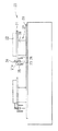
図1は、実施の形態1のスクライブ装置1の概略構成を示しており、図1(a)は側面図、図1(b)は平面図、図1(c)は正面図である。以下、この図1(a)〜(c)を用いて、本実施の形態1のスクライブ装置1を説明する。
【0018】
このスクライブ装置1は、平板状に形成された支持台2を有している。この支持台2の上面には、所定の照射エネルギーを有するレーザビームを発振するレーザ発振器3が支持台2に対して一体的に取り付けられている。この支持台2において、レーザ発振器3のレーザビーム出射側には、開口部2aが形成されており、この開口部2aの下面には、レーザ発振器3から照射されたレーザビームを入射して、所定の形状に整形した後、スクライブ対象となる脆性材料基板S表面に出射する光学系ユニット4が支持台2に対して一体的に取り付けられている。また、支持台2の開口部2a上方位置には、レーザ発振器3から照射されたレーザビームを開口部2aの下面に設けられた光学系ユニット4の方向に反射する2個のベンドミラー5が支持台2に対して一体的に設けられている。
【0019】
支持台2の下面には、光学系ユニット4の近傍位置に、冷却媒体を脆性材料基板Sの表面に吹き付ける冷却ジェット6が支持台2に対して一体的に取り付けられている。また、光学系ユニット4を挟んで冷却ジェット6の反対側には、脆性材料基板Sの端部等にスクライブラインの開始点(トリガ)となる切れ目を形成するためのトリガ機構7が設けられている。
【0020】
冷却ジェット6、光学系ユニット4、トリガ機構7は、スクライブ予定ラインに沿う同一直線上になるようにこの順にそれぞれ配置されている。冷却ジェット6と光学系ユニット4とは、脆性材料基板S上の冷却媒体の吹き付けにより形成される冷却領域とレーザビーム照射により形成される加熱領域とが近接した位置関係に形成されるようにするために、互いに近接して配置されている。トリガ機構7は、スクライブラインの開始点となる垂直クラックを形成することができれば、光学系ユニット4のレーザビーム照射により形成される加熱領域に対して近接していも離間していてもよいので、設置位置は任意でよい。
【0021】
また、レーザ発振器3、ベンドミラー5、光学系ユニット4、冷却ジェット6、トリガ機構7の各構成を一体的に取り付けた支持台2は、図示しない駆動機構により、スクライブ予定ラインに沿って移動可能になっており、スクライブラインを形成する際には、支持台2は、脆性材料基板Sに対してトリガ機構7側が先頭になる方向に移動される。また、支持台2は、この移動機構により、スクライブラインを形成するために好適な移動速度に調整される。
【0022】
レーザ発振器3から発振されるレーザビームは、脆性材料基板S上に形成される加熱領域の加熱温度が、脆性材料基板Sの表面が溶融することを防止するため、脆性材料基板Sが溶融される温度より低い、すなわち、脆性材料基板Sの軟化点よりも低くなるようなエネルギーのものが用いられる。この場合、スクライブ対象となる脆性材料基板Sの種類によって軟化点が異なるので、レーザ発振器3から発振されるレーザビームの照射エネルギーは、脆性材料基板Sの種類に応じて変更可能なように設定されることが好適である。
【0023】
光学系ユニット4では、レーザ発振器3から出射され2個のベンドミラー5を介して入射されたレーザビームを、スクライブラインの形成に適した所望の形状、例えば、スクライブ予定ライン方向に沿って長い長円形状に整形する。
【0024】
冷却ジェット6から吹き出される冷却媒体としては、使用が容易である点で冷却水が代表的であるが、冷却CO2ガス、N2ガス、Heガス等の気体状の冷却媒体、冷却有機溶媒等の液状の冷却媒体に変更することが可能である。
【0025】
トリガ機構7は、脆性材料基板Sの表面に近接する端部に、カッターホィール等の機械的手段が設けられて、脆性材料基板Sの所望の位置、例えば、端部部分において、脆性材料基板Sの表面に押圧することによりスクライブラインの開始点となる切れ目を形成する。この機械的手段は、脆性材料基板S上の所望位置以外では脆性材料基板Sを押圧しないことが必要であり、トリガ機構7には、この機械的手段を上下動させる上下移動機構(図示せず)が設けられている。また、脆性材料基板S表面に切れ目を形成する手段としては、機械的手段の他、YAGレーザ等の光学的手段を用いることも可能である。この場合、この光学的手段は、脆性材料基板Sの表面に対して非接触であるので、上下移動機構を設ける必要がない。
【0026】
次に、上記構成のスクライブ装置1を用いたスクライブ方法について説明する。
【0027】
まず、スクライブ対象となる脆性材料基板Sを、スクライブ装置1の光学系ユニット4、冷却ジェット6、トリガ機構7の下方位置に載置する。この載置時に、脆性材料基板Sは、脆性材料基板S表面のスクライブ予定ラインの方向とスクライブ装置1のスクライブ方向とが一致するように位置合わせが行われる。
【0028】
次に、移動機構を駆動させることにより、光学系ユニット4、冷却ジェット6、トリガ機構7を一体的に取り付けた支持台2を脆性材料基板Sに対して移動させる。支持台2を移動させると、まず、トリガ機構7が脆性材料基板Sの端部に達する。この端部位置で、トリガ機構7の先端に取り付けられたホィールカッター等の機械手段を脆性材料基板Sの表面に押圧させることにより、この位置にスクライブラインの開始点となる切れ目を形成する。
【0029】
脆性材料基板Sの表面に切れ目が形成された後、脆性材料基板Sの表面に意図しない傷等が生じないように、トリガ機構7の先端の機械手段が脆性材料基板Sの表面に対して非接触の状態とし、さらに、支持台2の移動を続ける。そして、支持台2下面の光学ユニット4、冷却ジェット6が脆性材料基板Sの表面に達した時点で、レーザー発振器3を駆動し始め、また、冷却ジェット6から冷却水等の冷却媒体の吹き付けを開始する。
【0030】
レーザ発振器3を駆動すると、所定エネルギーを有するレーザビームが発振される。発振されたレーザビームは、2個のベンドミラー5にて支持台2に形成された開口部2aの方向に反射され、開口部2aを通過したレーザビームは、光学系ユニット4に入射される。レーザビームが入射された光学系ユニット4では、レーザビームが長円形状等の所望の形状とされて、脆性材料基板Sの表面に向けて照射される。脆性材料基板Sの表面では、照射されたレーザビームのレーザスポットに対応した加熱領域が形成される。
【0031】
冷却ジェット6からは、冷却水等の冷却媒体が脆性材料基板Sの表面に吹き付けられて、レーザビームの照射による加熱領域に近傍した位置に、冷却領域が形成される。
【0032】
脆性材料基板Sの表面に形成された加熱領域では、圧縮応力が発生し、冷却媒体が吹き付けられた冷却領域では、引張り応力が発生する。このようなレーザビーム照射による圧縮応力及びその後方側に形成される冷却媒体による冷却領域の引張り応力を脆性材料基板S上のスクライブ予定ライン上に形成させ、これらの加熱領域及び冷却領域をスクライブ予定ライン上に順次移動させることにより、脆性材料基板Sの端部に形成された切れ目から垂直方向のクラックが連続して形成され、所望のスクライブラインが形成される。
【0033】
本実施の形態1のスクライブ装置1では、レーザ発振器3、ベンドミラー5、光学系ユニット4、冷却ジェット6、トリガ機構7のスクライブラインの形成に必要な全ての構成が支持台2に対して、一体的に取り付けられている。このため、各構成を脆性材料基板Sの表面に対して移動させても、レーザビームの脆性材料基板Sの表面に対する光路に変動が生じることが防止され、脆性材料基板Sの表面に照射されるレーザビームのビーム形状が変動することがない。また、冷却ジェット6から吹き付けられる冷却媒体の吹き付け位置が変動することがなく、一定している。したがって、安定したスクライブラインの形成を維持することができ、スクライブラインを形成した後に実施されるブレイク工程を経て分断される脆性材料基板Sの安定した分断面の品質を確保することができる。
【0034】
なお、本実施の形態1では、支持台2が移動する例を説明したが支持台2に対して脆性材料基板Sを移動させてもよい。
【0035】
(実施の形態2)
図2は、本実施の形態2のスクライブ装置10を示す側面図である。
【0036】
このスクライブ装置10は、上述の図1に示す実施の形態1のスクライブ装置1と概略同一の構成を有するものであり、この実施の形態1のスクライブ装置1の構成に加えて、トリガ機構7及び冷却ジェット6を、それぞれ、光学系ユニット4に対する両側に設け、さらに、支持台2を移動させる移動機構を前後の両方向に移動可能に構成したものである。このスクライブ装置10において、前述のスクライブ装置1と同一の構成については、同一の参照符号を付している。
【0037】
本実施の形態2のスクライブ装置10では、このように、光学系ユニット4の前後の両側にトリガ機構7及び冷却ジェット6がそれぞれ設けられているので、脆性材料基板Sに対する1回のスクライブが終了した後、脆性材料基板Sの位置を移動させて、1回目のスクライブとは逆方向に支持台2を移動させることにより、引き続いて、スクライブラインを形成することができる。
【0038】
したがって、本実施の形態2のスクライブ装置10では、実施の形態1のスクライブ装置1によって得られる効果に加えて、往復切断を可能とすることから、さらに、加工処理時間の短縮化を図ることが可能であり、大板の脆性材料基板のスクライブラインの形成に適するものとすることができる。
【0039】
なお、本実施の形態2では、支持台2が移動する例を説明したが支持台2に対して脆性材料基板Sを移動させてもよい。
【0040】
(実施の形態3)
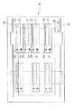
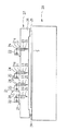
図3〜図5は、実施の形態3のスクライブ装置20の概略構成を示しており、図3は側面図、図4は平面図、図5は正面図を、それぞれ示している。以下、この図3〜図5を用いて、本実施の形態3のスクライブ装置20について説明する。
【0041】
このスクライブ装置20は、平板状に形成された支持台21を有している。この支持台21の上面には、所定の照射エネルギーを有するレーザビームを発振するレーザ発振器22が支持台21に対して一体的に取り付けられている。この支持台21において、レーザ発振器22のレーザビーム出射側には、開口部21aが形成されており、この開口部21aの下面には、レーザ発振器22から照射されたレーザビームを入射して、所定形状に整形した後、スクライブ対象となる脆性材料基板Sの表面に出射する光学系ユニット23が支持台21に対して一体的に取り付けられている。また、支持台21の開口部21aの上方位置には、レーザ発振器22から照射されたレーザビームを開口部21aの下面に設けられた光学系ユニット23の方向に反射する2個のベンドミラー24が支持台21に対して一体的に設けられている。
【0042】
支持台21の下面には、光学系ユニット23の近傍位置に、冷却媒体を脆性材料基板Sの表面に吹き付ける冷却ジェット25が支持台に対して一体的に取り付けられている。また、光学系ユニット23を挟んで冷却ジェット25の反対側には、脆性材料基板Sの端部等にスクライブラインの開始点(トリガー)となる切れ目を形成するためのトリガ機構26が設けられている。
【0043】
本実施の形態3では、このようなレーザ発振器22、ベンドミラー24、光学系ユニット23、冷却ジェット25、トリガ機構26を一つの構成ユニットとして一体的に取り付けた支持台21を、複数個有しており、一つの脆性材料基板Sに対して、1回のスクライブで、同時に複数箇所にわたってスクライブラインを形成することを実現するものである。
【0044】
すなわち、本実施の形態3のスクライブ装置20では、複数の支持台21が一つの移動機構27に設置されている。移動機構27は、各支持台21を設置する移動台部28を有している。また、このスクライブ装置20では、移動機構27の移動台部28の両側にスクライブ予定ラインと平行な一対のガイドレール29が形成されており、移動台部28がこのガイドレール29上に乗せられて、スクライブ予定ライン上に移動可能になっている。この移動台部28は、図示しない駆動手段によって、ガイドレール29に沿って移動される。
【0045】
なお、各支持台21を備えた移動台部28を固定して、図示しない移動手段により、脆性材料基板Sを移動させてスクライブしてもよい。
【0046】
また、移動台部28上に設けられた各支持台21は、図4の点線に示すように、移動台部28上を、スクライブ予定ラインに直交する方向に位置調整可能となっており、脆性材料基板Sの表面上の所望の位置にスクライブラインを形成することができるようになっている。
【0047】
レーザ発振器22等の詳細については、実施の形態1のレーザ発振器1等と同一であるので、ここでは、これら各構成の詳細については説明を省略する。
【0048】
また、このスクライブ装置20を用いたスクライフ方法についても、実施の形態1のスクライブ装置1を用いたスクライブ方法と同一であるので、詳細な説明は省略する。ただし、本実施の形態3では、レーザ発振器22等のスクライブラインの形成に必要な構成を1ユニットとして備えた支持台21を複数有しているので、一つの脆性材料基板Sに対して、1回のスクライブで、同時に、複数のスクライブラインを形成することができる。
【0049】
このように、本実施の形態3のスクライブ装置20では、1回のスクライブで、同時に複数のスクライブラインを形成することができるので、実施の形態1のスクライブ装置1に比較して、さらに、加工処理時間の短縮化を図ることが可能になる。
【0050】
このように、本実施の形態3のスクライブ装置20では、スクライブに必要なレーザ発振器22等の構成を1ユニットとして一体的に構成して簡易化された支持台21を複数備えることにより、一つの脆性材料基板Sに対して、複数のスクライブラインの形成を同時に実施することができ、大板の脆性材料基板に対して、多数のスクライブラインを形成するのに適している。
【0051】
なお、本実施の形態3では、各支持台21を実施の形態1のスクライブ装置の支持台2と同一構成として、一方向にのみスクライブ可能としたが、実施の形態2に説明したスクライブ装置10の支持台2と同様にトリガ機構7及び冷却ジェット6をそれそれ光学系ユニット4に対する両側に設け、さらに、支持台を前後両方向に移動可能に構成してもよい。このように構成すれば、前後両方向にスクライブ可能となり、加工処理時間をさらに短縮することが可能になる。
【0052】
【発明の効果】
以上説明した本発明のスクライブ装置は、脆性材料基板上に加熱領域を形成する加熱手段と、該加熱領域に近接した位置に冷却領域を形成する冷却手段と、スクライブラインの開始点となる切れ目を形成する切れ目形成手段とを、一体的に固定する固定手段を備え、該固定手段によって、該加熱手段、該冷却手段及び該切れ目形成手段が該脆性材料基板に対して一定の位置関係を維持しながら移動させられることを特徴としている。本発明のスクライブ装置では、スクライブ形成に必要な各構成を脆性材料基板の表面に対して移動させても、加熱領域及び冷却領域の形成位置に変動が生じることが防止される。したがって、安定したスクライブラインの形成を維持することができ、スクライブラインを形成した後に実施されるブレイク工程を経て分断される脆性材料基板Sの安定した分断面の品質を確保することができる。
【0053】
また、本発明の他のスクライブ装置では、冷却手段及び切れ目形成手段が、前記加熱手段を挟んで、前記脆性材料基板の進行方向の両側にそれぞれ配置されており、前記固定手段が該脆性材料基板に対して、前進方向及び後進方向のいずれに移動しても脆性材料基板にスクライブ可能になっている。これにより、加工処理時間の短縮化を図ることが可能であり、大板の脆性材料基板のスクライブラインの形成に適するものとすることができる。
【0054】
また、本発明のさらに他のスクライブ装置では、加熱手段及び冷却手段及び切れ目形成手段を一体に固定した固定手段を、複数設置し、各固定手段を同一方向に移動させることができる移動手段を有し、該移動手段の移動によって各固定手段が同一の方向に移動させられて前記脆性材料基板の表面が同時に複数箇所においてスクライブラインが形成されるようにしている。これにより、一つの脆性材料基板に対して、1回のスクライブで複数のスクライブラインを形成することができ、加工処理時間の短縮化を図ることが可能であり、大板の脆性材料基板のスクライブラインの形成に適するものとすることができる。
【図面の簡単な説明】
【図1】実施の形態1のスクライブ装置の概略構成を示しており、(a)は側面図、(b)は平面図、(c)は正面図である。
【図2】実施の形態2のスクライブ装置を示す側面図である。
【図3】実施の形態3のスクライブ装置を示す側面図である。
【図4】実施の形態3のスクライブ装置を示す平面図である。
【図5】実施の形態3のスクライブ装置を示す正面図である。
【図6】レーザビーム照射を用いた脆性材料基板の分断方法を説明するための模式図である。
【符号の説明】
1 スクライブ装置
2 支持台
3 レーザ発振器
4 光学系ユニット
5 ベンドミラー
6 冷却ジェット
7 トリガ機構
10 スクライブ装置
20 スクライブ装置
21 支持台
22 レーザ発振器
23 光学系ユニット
24 ベンドミラー
25 冷却ジェット
26 トリガ機構
27 移動機構
28 移動台部
29 ガイドレール[0001]
BACKGROUND OF THE INVENTION
The present invention relates to a scribing apparatus suitable for forming a scribe line on a large brittle material substrate.
[0002]
[Prior art]
In order to cut a brittle material substrate typified by a glass substrate or the like, a scribing process for forming a scribe line in which vertical cracks, which are cracks formed at a predetermined depth from the surface on the brittle material substrate, are continued in a desired direction. And, following this scribing process, a break process for dividing the brittle material substrate along a scribe line formed in the scribing process by applying a pressing force to the brittle material substrate is generally performed. It has become a method.
[0003]
In a scribing process performed when a brittle material substrate is cut, a method of forming a scribe line using a wheel cutter made of cemented carbide or sintered diamond is known. However, in the method using such a wheel cutter, the cullet generated during the formation of the scribe line may adhere to the surface of the brittle material substrate, which causes display defects when used in a display device or the like. Moreover, when performing the breaking process which divides | segments a brittle material board | substrate, an undesired chip | tip may arise in the edge part etc. of a brittle material board | substrate, and there exists a possibility that the quality of the brittle material board | substrate after division | segmentation may become defective.
[0004]
On the other hand, in recent years, a method of forming a scribe line using a laser beam has been put into practical use. In the method of forming a scribe line using this laser beam, the laser beam LB is irradiated from the
[0005]
Further, a cooling medium such as cooling water is sprayed from the
[0006]
In the method of forming a scribe line using the laser beam as described above, the occurrence of cullet is extremely small, and thermal strain stress is used for forming the scribe line. Therefore, a brittle material substrate is used when performing the breaking process. Chipping is less likely to occur on
[0007]
[Problems to be solved by the invention]
The above scribe line forming method using laser beam irradiation is mainly applied when scribing a small glass substrate or the like used in a liquid crystal display device, but also when scribing a large glass substrate. It is possible to scribe by the same principle.
[0008]
In a laser scribing apparatus for scribing a large glass substrate, a laser oscillator that oscillates a laser beam of a predetermined wavelength is installed at a position separated from the large glass substrate to be scribed, and a transmission system such as a mirror is used. Therefore, it is designed to transmit the energy of the beam to the optical system head installed on the scribe line forming surface of the large glass substrate. A cooling nozzle for spraying a cooling medium is provided in the vicinity of the optical head. When a scribe line is formed on a large glass substrate using this scribe device, the optical system head and the cooling system are arranged along a desired scribe line direction with respect to the fixed large glass substrate. The nozzle is scanned, and a crack is developed in advance from a cut formed in the end portion by heating by irradiation with a laser beam and cooling by a cooling medium from a cooling nozzle, thereby forming a desired scribe line.
[0009]
However, in such an apparatus configuration, it is necessary to move the optical head and the cooling nozzle on the large glass substrate in order to form a scribe line on the large glass substrate. As the cooling nozzle moves, the optical path of the laser beam with respect to the glass substrate surface changes, the beam shape formed on the glass substrate surface changes, and the spraying position of the cooling medium blown from the cooling nozzle is changed. fluctuate. For this reason, it is difficult to maintain the formation of a stable scribe line due to the occurrence of such fluctuations. Therefore, after breaking the glass substrate along the scribe line, the quality of the sectional surface of the stable glass substrate is reduced. There is a problem that it is difficult to ensure.
[0010]
Further, in the above scribing apparatus, it is difficult to install a plurality of optical heads on the same large glass substrate surface, so that it is difficult to shorten the processing time (tact). .
[0011]
The present invention has been made in view of the above circumstances, and in the case where a scribe line is formed using laser beam irradiation and cooling by a cooling medium, optical path variation with respect to the scribe line forming surface of the brittle material substrate is completely eliminated. In addition, since a plurality of optical heads can be installed, the processing time can be shortened, and a scribing apparatus suitable for scribing a large brittle material substrate is provided. For the purpose.
[0012]
[Means for Solving the Problems]
In order to solve the above problems, a scribing apparatus of the present invention includes a heating unit that forms a heating region on a brittle material substrate, a cooling unit that forms a cooling region near the heating region, and a starting point of a scribe line. A scribing device that forms a scribe line that is a continuation of vertical cracks developed from the cut by a stress gradient generated between the heating region and the cooling region. Fixing means for integrally fixing the heating means, the cooling means, and the cut forming means, and the heating means, the cooling means, the cut forming means, and the brittle material substrate fixed to the fixing means. Are moved while maintaining a relatively constant positional relationship with each other at a predetermined relative speed.
[0013]
In the scribing apparatus of the present invention, the heating means includes a laser oscillator that oscillates a laser beam, an optical unit that shapes the laser oscillated by the laser oscillator into a predetermined shape and irradiates the brittle material substrate, and the laser A transmission means arranged between an oscillator and the optical unit and transmitting a laser beam emitted from the laser oscillator to the optical unit, the laser oscillator, the optical unit and the transmission means being fixed It is preferable to be integrally fixed to the means.
[0014]
In the scribing apparatus of the present invention, the cooling means and the cut forming means are respectively arranged on both sides of the moving direction with the heating means interposed therebetween, and the fixing means advances and moves with respect to the brittle material substrate. It is preferable that scribing is possible regardless of the direction of reverse travel.
[0015]
In the scribing apparatus of the present invention, it is preferable that a plurality of the fixing means are provided, and a scribe line is simultaneously formed at a plurality of locations on the brittle material substrate.
[0016]
DETAILED DESCRIPTION OF THE INVENTION
Hereinafter, the scribing apparatus of the present invention will be described in detail.
[0017]
(Embodiment 1)
FIG. 1 shows a schematic configuration of the scribing apparatus 1 according to the first embodiment. FIG. 1 (a) is a side view, FIG. 1 (b) is a plan view, and FIG. 1 (c) is a front view. Hereinafter, the scribing apparatus 1 according to the first embodiment will be described with reference to FIGS.
[0018]
This scribing device 1 has a
[0019]
A cooling jet 6 that blows a cooling medium onto the surface of the brittle material substrate S is integrally attached to the lower surface of the support table 2 in the vicinity of the
[0020]
The cooling jet 6, the
[0021]
In addition, the
[0022]
The laser beam oscillated from the
[0023]
In the
[0024]
The cooling medium blown out from the cooling jet 6 is typically cooling water because it is easy to use. However, a gaseous cooling medium such as a cooling CO 2 gas, N 2 gas, or He gas, or a cooling organic solvent. It is possible to change to a liquid cooling medium such as.
[0025]
The trigger mechanism 7 is provided with mechanical means such as a cutter wheel at an end portion close to the surface of the brittle material substrate S, and at a desired position of the brittle material substrate S, for example, at the end portion, the brittle material substrate S. By pressing against the surface, a cut is formed which becomes the starting point of the scribe line. This mechanical means needs to not press the brittle material substrate S except at a desired position on the brittle material substrate S, and the trigger mechanism 7 has a vertical movement mechanism (not shown) for moving the mechanical means up and down. ) Is provided. Further, as means for forming a cut in the surface of the brittle material substrate S, optical means such as YAG laser can be used in addition to mechanical means. In this case, since this optical means is not in contact with the surface of the brittle material substrate S, it is not necessary to provide a vertical movement mechanism.
[0026]
Next, a scribing method using the scribing apparatus 1 having the above configuration will be described.
[0027]
First, the brittle material substrate S to be scribed is placed below the
[0028]
Next, the
[0029]
After the cut is formed on the surface of the brittle material substrate S, the mechanical means at the tip of the trigger mechanism 7 is not in contact with the surface of the brittle material substrate S so that unintended scratches or the like are not generated on the surface of the brittle material substrate S. The state of contact is set, and the movement of the
[0030]
When the
[0031]
A cooling medium such as cooling water is sprayed from the cooling jet 6 onto the surface of the brittle material substrate S, and a cooling region is formed at a position near the heating region by laser beam irradiation.
[0032]
In the heating region formed on the surface of the brittle material substrate S, compressive stress is generated, and in the cooling region where the cooling medium is sprayed, tensile stress is generated. The compressive stress caused by the laser beam irradiation and the tensile stress in the cooling region due to the cooling medium formed behind the laser beam are formed on the scribe line on the brittle material substrate S, and the heating region and the cooling region are scheduled to be scribed. By sequentially moving on the line, vertical cracks are continuously formed from the cuts formed at the end of the brittle material substrate S, and a desired scribe line is formed.
[0033]
In the scribing apparatus 1 according to the first embodiment, all configurations necessary for forming a scribe line for the
[0034]
In the first embodiment, the example in which the
[0035]
(Embodiment 2)
FIG. 2 is a side view showing the
[0036]
The
[0037]
In the
[0038]
Therefore, in addition to the effect obtained by the scribing apparatus 1 of the first embodiment, the
[0039]
In the second embodiment, the example in which the
[0040]
(Embodiment 3)
3-5 has shown schematic structure of the
[0041]
The
[0042]
A cooling
[0043]
In the third embodiment, there are provided a plurality of
[0044]
That is, in the
[0045]
Alternatively, the movable table 28 provided with each support table 21 may be fixed, and the brittle material substrate S may be moved and scribed by a moving means (not shown).
[0046]
Further, as shown by the dotted lines in FIG. 4, each support table 21 provided on the moving
[0047]
The details of the
[0048]
Further, the scribing method using the
[0049]
As described above, in the
[0050]
As described above, the
[0051]
In the third embodiment, each
[0052]
【The invention's effect】
The scribing apparatus of the present invention described above includes a heating unit that forms a heating region on a brittle material substrate, a cooling unit that forms a cooling region in a position close to the heating region, and a break that is the starting point of the scribe line. Fixing means for integrally fixing the cut forming means to be formed, and the fixing means maintains the fixed positional relationship between the heating means, the cooling means and the cut forming means with respect to the brittle material substrate. It is characterized by being moved while. In the scribing apparatus of the present invention, even if each component necessary for scribe formation is moved with respect to the surface of the brittle material substrate, it is possible to prevent fluctuations in the formation positions of the heating region and cooling region. Therefore, the formation of a stable scribe line can be maintained, and the quality of the stable sectional surface of the brittle material substrate S that is divided through the breaking process performed after the scribe line is formed can be ensured.
[0053]
Further, in another scribing apparatus of the present invention, the cooling means and the cut forming means are arranged on both sides in the traveling direction of the brittle material substrate across the heating means, and the fixing means is the brittle material substrate. On the other hand, it is possible to scribe the brittle material substrate regardless of whether it moves in the forward direction or the reverse direction. Thereby, it is possible to shorten the processing time and to be suitable for forming a scribe line of a large brittle material substrate.
[0054]
The scribing apparatus according to the present invention further includes a moving means that can install a plurality of fixing means that integrally fix the heating means, the cooling means, and the cut forming means, and can move each fixing means in the same direction. Then, the fixing means are moved in the same direction by the movement of the moving means so that scribe lines are formed simultaneously at a plurality of locations on the surface of the brittle material substrate. Accordingly, a plurality of scribe lines can be formed with one scribing on one brittle material substrate, and the processing time can be shortened. It can be suitable for forming a line.
[Brief description of the drawings]
1A and 1B show a schematic configuration of a scribing apparatus according to Embodiment 1, wherein FIG. 1A is a side view, FIG. 1B is a plan view, and FIG.
FIG. 2 is a side view showing a scribing apparatus according to a second embodiment.
FIG. 3 is a side view showing a scribing device according to a third embodiment.
4 is a plan view showing a scribing apparatus according to
FIG. 5 is a front view showing a scribing device according to a third embodiment.
FIG. 6 is a schematic diagram for explaining a method of dividing a brittle material substrate using laser beam irradiation.
[Explanation of symbols]
DESCRIPTION OF SYMBOLS 1
Claims (4)
該加熱手段、該冷却手段及び該切れ目形成手段を一体的に固定する固定手段を備え、該固定手段に固定された該加熱手段、該冷却手段及び該切れ目形成手段と該脆性材料基板とが互いに所定の相対速度にて相対的に一定の位置関係を維持しながら移動することを特徴とするスクライブ装置。A heating unit that forms a heating region on the brittle material substrate, a cooling unit that forms a cooling region near the heating region, and a cut forming unit that forms a cut serving as a starting point of a scribe line, A scribing device that forms a scribe line that is a continuation of vertical cracks developed from the cut by a stress gradient generated between a heating region and the cooling region,
The heating means, the cooling means, and the cut forming means are provided with fixing means for integrally fixing the heating means, the cooling means, the cut forming means, and the brittle material substrate fixed to the fixing means. A scribing apparatus that moves while maintaining a relatively constant positional relationship at a predetermined relative speed.
Priority Applications (4)
| Application Number | Priority Date | Filing Date | Title |
|---|---|---|---|
| JP2002202578A JP2004042423A (en) | 2002-07-11 | 2002-07-11 | Scribing apparatus |
| TW092114861A TW200400863A (en) | 2002-07-11 | 2003-06-02 | Scribe device |
| KR1020030037330A KR20040007251A (en) | 2002-07-11 | 2003-06-11 | A scribing apparatus |
| CNB031459129A CN1328194C (en) | 2002-07-11 | 2003-07-11 | Layout liner |
Applications Claiming Priority (1)
| Application Number | Priority Date | Filing Date | Title |
|---|---|---|---|
| JP2002202578A JP2004042423A (en) | 2002-07-11 | 2002-07-11 | Scribing apparatus |
Publications (1)
| Publication Number | Publication Date |
|---|---|
| JP2004042423A true JP2004042423A (en) | 2004-02-12 |
Family
ID=30437330
Family Applications (1)
| Application Number | Title | Priority Date | Filing Date |
|---|---|---|---|
| JP2002202578A Pending JP2004042423A (en) | 2002-07-11 | 2002-07-11 | Scribing apparatus |
Country Status (4)
| Country | Link |
|---|---|
| JP (1) | JP2004042423A (en) |
| KR (1) | KR20040007251A (en) |
| CN (1) | CN1328194C (en) |
| TW (1) | TW200400863A (en) |
Cited By (6)
| Publication number | Priority date | Publication date | Assignee | Title |
|---|---|---|---|---|
| JP2009242184A (en) * | 2008-03-31 | 2009-10-22 | Nippon Electric Glass Co Ltd | Cutting method and cutting device for brittle platy object |
| KR100932347B1 (en) * | 2006-07-21 | 2009-12-16 | 폭스세미콘 인티그리티드 테크놀로지, 인코포레이티드 | Laser cutting apparatus and laser cutting method |
| KR100958745B1 (en) * | 2009-11-30 | 2010-05-19 | 방형배 | Laser scribing apparatus, method, and laser scribing head |
| KR101031235B1 (en) * | 2005-02-02 | 2011-04-29 | 미쓰보시 다이야몬도 고교 가부시키가이샤 | Method of working sintered diamond |
| CN102344245A (en) * | 2005-07-06 | 2012-02-08 | 三星钻石工业股份有限公司 | Brittle material scribing wheel and method, device and tool for manufacturing such brittle material scribing wheel |
| JP6027654B1 (en) * | 2015-04-24 | 2016-11-16 | エイゾクケイマングントウショウナノコウフンユウゲンコウシ | Brittle material cutting device and method for cutting the same |
Families Citing this family (10)
| Publication number | Priority date | Publication date | Assignee | Title |
|---|---|---|---|---|
| KR100573259B1 (en) * | 2004-06-28 | 2006-04-24 | 주식회사에스엘디 | Laser cutting machine using thermally induced crack propagation technique |
| JP4675786B2 (en) * | 2006-01-20 | 2011-04-27 | 株式会社東芝 | Laser cleaving device, cleaving method |
| KR100949152B1 (en) * | 2007-11-23 | 2010-03-25 | 삼성코닝정밀유리 주식회사 | Apparatus for cutting glass using laser |
| CN102089115A (en) * | 2008-05-30 | 2011-06-08 | 三星钻石工业股份有限公司 | Laser working apparatus, and laser working method |
| JP5332344B2 (en) * | 2008-06-30 | 2013-11-06 | 三星ダイヤモンド工業株式会社 | Chip holder and holder unit |
| JP6424652B2 (en) * | 2015-02-02 | 2018-11-21 | 三星ダイヤモンド工業株式会社 | Holder, holder unit and scribing device |
| CN107378908A (en) * | 2017-09-08 | 2017-11-24 | 广州市盛吉成智能科技有限公司 | A kind of high-end shear line dispenser |
| CN111055256A (en) * | 2019-12-30 | 2020-04-24 | 湖南三一快而居住宅工业有限公司 | Double-end marking device and double-end marking system |
| CN114734153B (en) * | 2022-03-31 | 2023-02-14 | 武汉华日精密激光股份有限公司 | Splitting method and system for processing brittle material by laser |
| CN116352293B (en) * | 2023-06-02 | 2023-08-25 | 沧州领创激光科技有限公司 | Laser cutting machine |
Family Cites Families (3)
| Publication number | Priority date | Publication date | Assignee | Title |
|---|---|---|---|---|
| RU2024441C1 (en) * | 1992-04-02 | 1994-12-15 | Владимир Степанович Кондратенко | Process of cutting of nonmetal materials |
| MY120533A (en) * | 1997-04-14 | 2005-11-30 | Schott Ag | Method and apparatus for cutting through a flat workpiece made of brittle material, especially glass. |
| DE19952331C1 (en) * | 1999-10-29 | 2001-08-30 | Schott Spezialglas Gmbh | Method and device for quickly cutting a workpiece from brittle material using laser beams |
-
2002
- 2002-07-11 JP JP2002202578A patent/JP2004042423A/en active Pending
-
2003
- 2003-06-02 TW TW092114861A patent/TW200400863A/en not_active IP Right Cessation
- 2003-06-11 KR KR1020030037330A patent/KR20040007251A/en not_active Application Discontinuation
- 2003-07-11 CN CNB031459129A patent/CN1328194C/en not_active Expired - Fee Related
Cited By (7)
| Publication number | Priority date | Publication date | Assignee | Title |
|---|---|---|---|---|
| KR101031235B1 (en) * | 2005-02-02 | 2011-04-29 | 미쓰보시 다이야몬도 고교 가부시키가이샤 | Method of working sintered diamond |
| CN102344245A (en) * | 2005-07-06 | 2012-02-08 | 三星钻石工业股份有限公司 | Brittle material scribing wheel and method, device and tool for manufacturing such brittle material scribing wheel |
| CN102344245B (en) * | 2005-07-06 | 2015-10-28 | 三星钻石工业股份有限公司 | The scribble method of scribing wheel for brittle material and this tracing wheel of employing and device, instrument |
| KR100932347B1 (en) * | 2006-07-21 | 2009-12-16 | 폭스세미콘 인티그리티드 테크놀로지, 인코포레이티드 | Laser cutting apparatus and laser cutting method |
| JP2009242184A (en) * | 2008-03-31 | 2009-10-22 | Nippon Electric Glass Co Ltd | Cutting method and cutting device for brittle platy object |
| KR100958745B1 (en) * | 2009-11-30 | 2010-05-19 | 방형배 | Laser scribing apparatus, method, and laser scribing head |
| JP6027654B1 (en) * | 2015-04-24 | 2016-11-16 | エイゾクケイマングントウショウナノコウフンユウゲンコウシ | Brittle material cutting device and method for cutting the same |
Also Published As
| Publication number | Publication date |
|---|---|
| CN1472032A (en) | 2004-02-04 |
| KR20040007251A (en) | 2004-01-24 |
| TW200400863A (en) | 2004-01-16 |
| TWI292352B (en) | 2008-01-11 |
| CN1328194C (en) | 2007-07-25 |
Similar Documents
| Publication | Publication Date | Title |
|---|---|---|
| JP4156513B2 (en) | Scribing method and scribing apparatus for brittle material substrate | |
| JP2004042423A (en) | Scribing apparatus | |
| JP2011230940A (en) | Cutting method for brittle material substrate | |
| JP5562254B2 (en) | Brittle material splitting apparatus and splitting method | |
| KR100647454B1 (en) | Device and method for scribing substrate of brittle material | |
| JP2007090860A (en) | System and method for cutting and working fragile material | |
| WO2003008352A1 (en) | Device and method for scribing fragile material substrate | |
| JP4080484B2 (en) | Scribing method and scribing apparatus for brittle material substrate | |
| JPH08175837A (en) | Method for dividing plate glass and device therefor | |
| CN102123817A (en) | Chamfering apparatus | |
| JP5202595B2 (en) | Laser cleaving device | |
| CN101934427A (en) | Method for cutting brittle material substrate | |
| KR101442067B1 (en) | Method for dividing brittle material substrate | |
| JP5590642B2 (en) | Scribing apparatus and scribing method | |
| JPWO2003013816A1 (en) | Method and apparatus for scribing brittle material substrate | |
| JP2007301631A (en) | Cleaving apparatus and cleaving method | |
| JPH08231239A (en) | Method for cutting glass ribbon and device therefor | |
| JP2008050219A (en) | Scribing groove forming apparatus, cutting apparatus and scribing groove forming method | |
| JP2004035315A (en) | Method and apparatus for dividing brittle material substrates | |
| JP2002153984A (en) | Method for dividing substrate and method for manufacturing liquid crystal device using the same | |
| JP5444158B2 (en) | Cleaving method of brittle material substrate | |
| JP4149746B2 (en) | Method and apparatus for scribing hard brittle plate | |
| KR100659931B1 (en) | Apparatus for cutting a substrate by using laser and method for performing the same | |
| JP2012006320A (en) | Method for cutting brittle material substrate | |
| JP5678816B2 (en) | Glass substrate cleaving method and cleaving apparatus |
Legal Events
| Date | Code | Title | Description |
|---|---|---|---|
| A621 | Written request for application examination |
Free format text: JAPANESE INTERMEDIATE CODE: A621 Effective date: 20050617 |
|
| A977 | Report on retrieval |
Free format text: JAPANESE INTERMEDIATE CODE: A971007 Effective date: 20070720 |
|
| A131 | Notification of reasons for refusal |
Free format text: JAPANESE INTERMEDIATE CODE: A131 Effective date: 20070802 |
|
| A521 | Written amendment |
Free format text: JAPANESE INTERMEDIATE CODE: A523 Effective date: 20070927 |
|
| A02 | Decision of refusal |
Free format text: JAPANESE INTERMEDIATE CODE: A02 Effective date: 20080529 |