JP2004035315A - Method and apparatus for dividing brittle material substrates - Google Patents
Method and apparatus for dividing brittle material substrates Download PDFInfo
- Publication number
- JP2004035315A JP2004035315A JP2002193919A JP2002193919A JP2004035315A JP 2004035315 A JP2004035315 A JP 2004035315A JP 2002193919 A JP2002193919 A JP 2002193919A JP 2002193919 A JP2002193919 A JP 2002193919A JP 2004035315 A JP2004035315 A JP 2004035315A
- Authority
- JP
- Japan
- Prior art keywords
- brittle material
- material substrate
- heating
- region
- laser beam
- Prior art date
- Legal status (The legal status is an assumption and is not a legal conclusion. Google has not performed a legal analysis and makes no representation as to the accuracy of the status listed.)
- Pending
Links
Images


Classifications
-
- C—CHEMISTRY; METALLURGY
- C03—GLASS; MINERAL OR SLAG WOOL
- C03B—MANUFACTURE, SHAPING, OR SUPPLEMENTARY PROCESSES
- C03B33/00—Severing cooled glass
- C03B33/09—Severing cooled glass by thermal shock
- C03B33/091—Severing cooled glass by thermal shock using at least one focussed radiation beam, e.g. laser beam
- C03B33/093—Severing cooled glass by thermal shock using at least one focussed radiation beam, e.g. laser beam using two or more focussed radiation beams
-
- C—CHEMISTRY; METALLURGY
- C03—GLASS; MINERAL OR SLAG WOOL
- C03B—MANUFACTURE, SHAPING, OR SUPPLEMENTARY PROCESSES
- C03B33/00—Severing cooled glass
- C03B33/10—Glass-cutting tools, e.g. scoring tools
- C03B33/102—Glass-cutting tools, e.g. scoring tools involving a focussed radiation beam, e.g. lasers
-
- Y—GENERAL TAGGING OF NEW TECHNOLOGICAL DEVELOPMENTS; GENERAL TAGGING OF CROSS-SECTIONAL TECHNOLOGIES SPANNING OVER SEVERAL SECTIONS OF THE IPC; TECHNICAL SUBJECTS COVERED BY FORMER USPC CROSS-REFERENCE ART COLLECTIONS [XRACs] AND DIGESTS
- Y02—TECHNOLOGIES OR APPLICATIONS FOR MITIGATION OR ADAPTATION AGAINST CLIMATE CHANGE
- Y02P—CLIMATE CHANGE MITIGATION TECHNOLOGIES IN THE PRODUCTION OR PROCESSING OF GOODS
- Y02P40/00—Technologies relating to the processing of minerals
- Y02P40/50—Glass production, e.g. reusing waste heat during processing or shaping
- Y02P40/57—Improving the yield, e-g- reduction of reject rates
Abstract
Description
【0001】
【発明の属する技術分野】
本発明は、液晶表示装置等の表示装置に使用されるガラス基板等の脆性材料基板の分断方法及びその分断方法を実施するために使用される分断装置に関する。
【0002】
本明細書に記載されている脆性材料基板は、ガラス基板等を貼り合わせた貼り合わせ脆性材料基板を含む。
【0003】
【従来の技術】
ガラス基板等に代表される脆性材料基板を分断するには、脆性材料基板上の表面から所定深さに形成された亀裂である垂直クラックを所望の方向に連続させたスクライブラインを形成するスクライブ工程と、このスクライブ工程に続いて、脆性材料基板に対して押圧力を加えることによって、スクライブ工程で形成されたスクライブラインに沿って脆性材料基板を分断させるブレイク工程とを実施することが一般的な方法となっている。
【0004】
脆性材料基板を分断する場合に行われるスクライブ工程では、超硬合金製または焼結ダイヤモンド製のホィールカッターを用いてスクライブラインを形成する方法が知られている。しかし、このようなホィールカッターを用いる方法では、スクライブライン形成中に発生するカレットが脆性材料基板の表面に付着するおそれがあり、表示装置等に使用する場合には表示欠陥の原因となる。また、脆性材料基板を分断するブレイク工程を実施する際に、脆性材料基板の端面部分に所望でない欠けが生じ、分断後の脆性材料基板の品質が不良となるおそれもある。
【0005】
これに対して、近年になって、レーザービームを使用してスクライブラインを形成する方法が実用化されている。このレーザービームを使用してスクライブラインを形成する方法では、図7に示すように、分断対象となる脆性材料基板Sに対して、レーザー発振装置61からレーザービームLBが照射される。レーザー発振装置61から照射されるレーザービームLBは、スクライブ予定ラインに沿ってレーザースポットLSを脆性材料基板S上に形成する。レーザー発振装置61から照射されるレーザービームLBは、レーザー発振装置61が固定された脆性材料基板Sに対して移動するか、または、脆性材料基板Sが固定されたレーザー発振装置61に対して移動するか、または、レーザ発振装置61及び脆性材料基板Sのいずれもが移動するかにより、脆性材料基板S上をレーザ発振装置61のレーザスポットがスクライブ予定ラインに沿って移動するように設定される。
【0006】
また、脆性材料基板Sの表面におけるレーザービームLBの照射領域の近傍には、スクライブラインが形成されるように、冷却水等の冷却媒体が、冷却ノズル62から吹き付けられるようになっている。レーザービームLBが照射されるガラス基板の表面は、レーザービームLBによる加熱によって圧縮応力が生じた後に、冷却媒体が吹き付けられることにより、引張り応力が生じる。このように、圧縮応力が生じた領域に近接した領域に引張り応力が生じるために、両領域間に、それぞれの応力に基づく応力勾配が発生し、脆性材料基板には、脆性材料基板の端部にホィールカッター等により予め形成された切れ目からスクライブ予定ラインに沿うように連続したクラックが発生する。
【0007】
上記のようなレーザービームを使用してスクライブラインを形成する方法では、カレットの発生は極めて少なく、スクライブラインの形成に熱歪応力を利用しているので、ブレイク工程を実施する際に脆性材料端面に欠けが生じにくい。
【0008】
【発明が解決しようとする課題】
分断対象となる脆性材料基板が1枚の板状に構成された単板である場合、脆性材料基板の片面に対して、上記のレーザービームを用いたスクライブ工程を実施した後に、スクライブラインを形成した脆性材料基板の表裏を反転して、スクライブラインが形成されていない裏面が上側になるようにした後に、スクライブラインが形成された側に対して反対側である裏面に対して、スクライブラインと対向したラインに沿って押圧力を加えるブレイク工程を行うことにより単板の脆性材料基板が分断される。
【0009】
この場合、スクライブ工程に続くブレイク工程にて、確実に脆性材料基板を分断することができ、また、良好な分断面を得るためには、スクライブ工程にて形成されるスクライブラインの垂直クラックは、深く形成されることが好ましい。しかし、垂直クラックが深い場合には、ブレイク工程を実施する前に、脆性材料基板を搬送及び表裏を反転する際に、脆性材料基板が分断された状態になり、分断された脆性材料基板がスクライブ工程を実施する装置内に残されるおそれがあり、さらには、脆性材料基板が搬送途中で落下するおそれもある。
【0010】
一方、分断対象となる脆性材料基板が、液晶表示装置等の用途のために一対の脆性材料基板を貼り合わせることにより構成される貼りあわせ脆性材料基板である場合、貼り合わされた一対の脆性材料基板のそれぞれに対して、スクライブ工程及びブレイク工程を実施する必要があるため、単板に比較して、分断するための工程が多工程にわたり、各工程を実施するため、脆性材料基板の搬送及び反転を繰り返し行うことが必要になる。
【0011】
したがって、脆性材料基板の一種である貼り合わせ脆性材料基板を分断する場合には、分断を実施するための工程が多工程にわたるという問題と共に、各工程が終了する毎に脆性材料基板を搬送及び反転させることが必要になるため、前述した搬送途中で脆性材料基板の落下等の問題が生じるおそれが、単板の場合よりも高くなる。
【0012】
したがって、分断対象となる脆性材料基板が単板、あるいは貼り合わせ基板のいずれである場合でも、スクライブ工程後の基板の搬送途中において脆性材料基板が分断され、落下して、基板を破損してしまい、歩留まりが低下するという問題がある。
【0013】
本発明は、上記問題点を解決するためになされたものであり、工程数を低減することができるとともに、製品の歩留まりが向上する、脆性材料基板の分断方法及びその分断方法を実施するための分断装置を提供することを目的とする。
【0014】
【課題を解決するための手段】
上記課題を解決するため、本発明の脆性材料基板の分断方法は、脆性材料基板の表面および裏面における相互に対応するように形成されるスクライブ予定ラインに沿って、該脆性材料基板の軟化点より低い温度でそれぞれ連続して同時に加熱して、加熱領域をそれぞれ形成しつつ、各加熱領域の近傍に冷却領域をそれぞれ連続して形成することにより、脆性材料基板の表面および裏面から該脆性材料基板を貫通する垂直クラックを形成して、該脆性材料基板を分断することを特徴とするものである。
【0015】
また、本発明の脆性材料基板分断装置は、脆性材料基板を該脆性材料基板の軟化点より低い温度で加熱して加熱領域を形成する加熱手段と、加熱領域に近傍した位置を冷却して冷却領域を形成する冷却手段とが、分断対象となる脆性材料基板の表面および裏面に、相互に対応するように、且つ、所定のスクライブ予定ライン方向に相対的に移動可能なように、それぞれ配置されて、該加熱領域と該冷却領域とによって形成される熱応力によって、該脆性材料基板の両面から該脆性材料基板を貫通して該脆性材料基板を分断する垂直クラックが形成されることを特徴とするものである。
【0016】
上記本発明の脆性材料基板分断装置において、前記加熱領域の前方を余熱する余熱手段がさらに設けられていることが好ましい。
【0017】
上記本発明の脆性材料基板分断装置において、前記冷却領域の後方を加熱する第二加熱手段がさらに設けられていることが好ましい。
【0018】
上記本発明の脆性材料基板分断装置において、前記第二加熱手段は、スクライブ予定ラインに沿う方向を対対称軸とするように、2つに分離して構成されていることが好ましい。
【0019】
【発明の実施の形態】
以下、本発明の脆性材料基板の分断方法及びその分断方法に用いられる分断装置について、詳細に説明する。
【0020】
本発明の脆性材料基板の分断方法は、脆性材料基板の表裏の両面に対して同方向に同時にレーザビームの照射及び冷却媒体の吹き付けを行うスクライブ工程を実施することを特徴としている。本発明の脆性材料基板の分断方法では、脆性材料基板の両面に対してスクライブ工程を実施することにより、1回のスクライブ工程で脆性材料基板の上下面に対して垂直クラックが貫通したフルボディカットの状態にして、脆性材料基板が完全分断された状態とし、従来方法において実施されていたスクライブ工程に続くブレイク工程を省略することができる。これにより、脆性材料基板を分断するための工程数を低減することができる。さらに、特に、脆性材料基板の一種である貼り合わせ脆性材料基板を分断する場合には、貼り合わせ脆性材料基板の一対の脆性材料基板のそれぞれに対して実施していたスクライブ工程及びブレイク工程のうちブレイク工程を省略することができるので、これに関連して、スクライブ工程からブレイク工程への搬送及び脆性材料基板の反転を行う必要がないので、脆性材料基板の搬送及び反転途中における脆性材料基板の落下等のおそれを防止することができる。この結果、脆性材料基板の分断の歩留まりを向上させることが可能になる。
【0021】
次に、本発明の脆性材料基板の分断方法を実施するための具体的な分断装置について、以下の実施の形態において図面を参照しながら説明する。
【0022】
(実施の形態1)
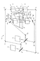
図1は、本実施の形態1の脆性材料基板の分断方法を実施するための分断装置1を示す模式図であり、シングルビームを脆性材料基板Sの表裏に照射することを特徴とするものである。
【0023】
この分断装置1は、所定の波長域のレーザービームを発振するレーザービーム発振装置2を有している。また、このレーザービーム発振装置2のレーザービーム出射側には、発振されたレーザービームの出力を分割するビームスプリッタ3が設けられている。
【0024】
脆性材料基板Sの表裏のそれぞれの側には、脆性材料基板Sに対して対称となるように、レーザスポット形成装置4が設けられている。ビームスプリッター3と各レーザスポット形成装置4との間には、ミラー等のビーム反射手段5が各所の適切な位置に設けられており、各レーザスポット形成装置4に、ビームスプリッタ3により分離されたそれぞれのレーザビームが入射されるようになっている。脆性材料基板Sの表裏のそれぞれの側に設けられたレーザスポット形成装置4は、入射されたレーザビームを所望の形状、例えば、スクライブ予定ラインに沿って長い長円形状等の形状にレーザスポットを調整する。
【0025】
各レーザスポット形成装置4は、脆性材料基板Sに対して対称である関係を維持しながら、脆性材料基板Sに対して一定の方向に相対的に移動可能になっている。ここで、相対的に移動可能とは、レーザスポット形成装置4を固定して脆性材料基板Sを移動させる場合、または、脆性材料基板Sを固定してレーザスポット形成装置4を移動させる場合、さらには、脆性材料基板S及びレーザスポット形成装置4を共に移動させる場合がある。
【0026】
また、脆性材料基板Sの表裏各面には、脆性材料基板Sの表裏面のそれぞれに冷却媒体を吹きつける冷却ノズル6が設けられている。各冷却ノズル6は、各レーザスポット形成装置4から照射されたレーザスポットAに対して、レーザスポットAの移動方向の後方側の近傍位置に、冷却媒体の吹き付けによる冷却領域Bが形成されるようになっている。各冷却ノズル6から吹き付けられる冷却媒体としては、使用が容易である点で冷却水が代表的であるが、冷却CO2ガス、N2ガス、Heガス等の気体状の冷却媒体、冷却有機溶媒等の他の液状の冷却媒体に変更することが可能である。
【0027】
次に、上記構成の分断装置1を用いた脆性材料基板Sの分断方法について説明する。
【0028】
レーザービーム発振装置2を駆動すると、所定の照射エネルギーを有するレーザービームが発振される。発振されたレーザービームは、ビームスプリッター3にて2方向のレーザービームに分離され、各分離されたレーザービームは、それぞれ、各所に配置されたビーム反射手段5にて反射されて、各レーザスポット形成装置4にそれぞれ入射される。レーザスポット形成装置4では、入射されたレーザービームが、長円形状等の所定の形状に形成されて、脆性材料基板Sの表裏面にそれぞれ照射される。脆性材料基板Sの表裏各面では、照射されたレーザービームのレーザスポットAに対応した加熱領域が形成される。
【0029】
ここで、脆性材料基板Sの表裏各面に形成される加熱領域の加熱温度は、レーザービームが照射された脆性材料基板Sの表裏各面が溶融することを防止するため、脆性材料基板Sが溶融される温度より低い、すなわち、脆性材料基板Sの軟化点よりも低い温度とされる。
【0030】
冷却ノズル6からは、レーザビームが照射される加熱領域のレーザスポットAの移動方向の後方側の近傍位置に、各冷却ノズル6から冷却媒体が吹き付けられて、冷却領域Bが形成される。
【0031】
また、分断対象となる脆性材料基板Sの表裏の各面のスクライブ予定ラインの端部位置には、図示しないカッターホィール等の機械的手段やYAGレーザー等の光学的手段により切れ目が形成されている。脆性材料基板Sの表裏の各面に形成されたレーザビーム照射による加熱領域では、圧縮応力が発生し、冷却媒体が吹き付けられた冷却領域には、引張り応力が発生する。このようなレーザービーム照射による圧縮応力及びその後方側に形成される冷却媒体による冷却領域の引張り応力を脆性材料基板S上のスクライブ予定ライン上に形成させ、これらの加熱領域及び冷却領域をスクライブ予定ライン上に順次移動させることにより、脆性材料基板Sの端部に予め形成された切れ目から垂直方向のクラックが連続して形成され、所望のスクライブラインが形成される。
【0032】
本実施の形態1では、このようなスクライブラインの形成を脆性材料基板Sの両面から実施するので、1回のスクライブ工程にて、垂直クラックが脆性材料基板Sの表裏を貫通した状態とすることができる。脆性材料基板が貼り合わせ脆性材料基板である場合は、レーザースポットA及び冷却スポットBの脆性材料基板Sに対しての移動速度(以下、相対速度と呼ぶ)を低速にすることで、上下の脆性材料基板を貫通する垂直クラックを得ることができ、一回のスクライブ工程で貼り合わせ脆性材料基板を分断することができる。したがって、従来、このスクライブ工程に引き続いて行われてきたブレイク工程を実施することが不要であり、脆性材料基板Sを分断するための工程数を低減することができる。また、各工程を実施することに伴う脆性材料基板Sの搬送及び反転を行った場合に発生していた脆性材料基板Sの落下等の不具合を回避することができ、歩留まりを向上させることができる。
【0033】
(実施の形態2)
図2は、本発明の脆性材料基板の分断方法を実施するための実施の形態2の分断装置10を示す模式図であり、脆性材料基板Sの表裏各面にそれぞれ2つのビームスポットを形成することを特徴とするものである。
【0034】
この分断装置10は、上記の図1に示す実施の形態1の分断装置1と概略同一の構成を有するものであり、図1の分断装置1の構成に加えて、レーザービームを照射することによる加熱領域のさらに前方に、余熱領域を形成するための構成を追加したものである。したがって、以下の実施の形態2の分断装置の説明では、図1に示す分断装置と同一の構成については、同一の参照符号を付して、詳しい説明は省略し、異なる構成についてのみ説明する。
【0035】
本実施の形態2の分断装置では、余熱ビームを発振する余熱ビーム発振装置11を有している。この余熱ビーム発振装置11から発振される余熱ビームは、脆性材料基板Sにレーザビームを照射して加熱領域を形成する前に、予め、ある程度余熱するために用いられるものであるので、レーザビーム発振装置2から発振されるレーザビームのエネルギーよりも幾分低エネルギーになるように設定される。
【0036】
この余熱ビーム発振装置11の余熱ビーム出射側には、発振された余熱ビームの出力を分割するビームスピリッター12が設けられている。
【0037】
脆性材料基板Sの表裏のそれぞれの側には、レーザスポット形成装置4のさらに前方側になるように、余熱スポット形成装置13が設けられている。ビームスプリッター12と各余熱スポット形成装置13との間には、ミラー等のビーム反射手段14が各所の適切な位置に設けられており、各余熱スポット形成装置13に、ビームスプリッター12により分離されたそれぞれの成分の余熱ビームが入射されるようになっている。脆性材料基板Sの表裏のそれぞれの側に設けられた余熱スポット形成装置13は、入射された余熱ビームを所望の形状、例えば、スクライブ予定ラインに沿って長い長円形状等の形状に余熱ビームスポットを調節する。さらに、この余熱ビームスポット形成装置13により形成される余熱スポットCは、脆性材料基板Sの所望の広範囲にわたって余熱を行うために、ビームスポット形成装置4によるレーザスポットAよりも大きい領域を占めるように形成される。図2に示す例では、レーザスポット形成装置4により形成されたレーザスポットAが、スクライブ予定ラインの方向に沿って長い長円形状に形成されており、余熱スポット形成装置13により形成される余熱スポットCが、この長円形状のビームスポットよりもさらに長い長円形状の形状とされている。
【0038】
次いで、脆性材料基板Sの分断方法について説明する。この分断方法についても、図1に示す分断装置を用いた方法と概略同様であるので共通する方法については詳しい説明は省略する。
【0039】
この実施の形態2では、余熱スポット形成装置13により、レーザスポット形成装置4により形成される加熱領域のさらに前方側に余熱領域を形成する。これにより、レーザスポット形成装置4からレーザービームが照射されても、予め、余熱領域が形成されているので、脆性材料基板Sが急激に温度上昇することを避けることができ、所望でない方向のクラックが発生することを避けることができる。また、レーザビームによる加熱を円滑に行うことができるので、レーザビームによる加熱領域を、脆性材料基板Sの厚み方向へより深く形成することが可能になる。このため、実施の形態1と比較して、相対速度を速くしてスクライブラインを形成させることができ、スクライブラインの形成を脆性材料基板Sの両面から実施するので1回のスクライブ工程にて垂直クラックが脆性材料基板Sの表裏を貫通した状態とすることができる。脆性材料基板が貼り合わせ脆性材料基板の場合は、上下の脆性材料基板を貫通する垂直クラックを得ることができ、1回のスクライブ工程にて貼り合わせ脆性材料基板を分断することができる。
【0040】
(実施の形態3)
図3は、本発明の脆性材料基板の分断方法を実施するめの実施の形態3の分断装置20を示す模式図であり、脆性材料基板Sの表裏各面に目的が異なるそれぞれ2つのビームスポットを形成することを特徴とするものである。
【0041】
この分断装置20は、上記の図1に示す実施の形態1の分断装置と概略同一の構成を有するものであり、図1の分断装置の構成に加えて、冷却ノズル6から冷却媒体を吹き付けることによる冷却領域のさらに後方に、第二加熱領域を形成するための構成を追加したものである。したがって、以下の実施の形態3の分断装置の説明では、図1に示す分断装置と同一の構成については、同一の参照符号を付して、詳しい説明は省略し、異なる構成についてのみ説明する。
【0042】
本実施の形態3の分断装置では、第二レーザービームを発振する第二レーザービーム発振装置21を有している。この第二レーザービーム発振装置21から発振される第二レーザービームは、前方側での引張り応力の発生により形成された垂直クラックに対して、さらに、冷却領域の後方側に第二の加熱領域を形成することにより、前方側にて形成された垂直クラックを脆性材料基板Sの厚み方向にさらに深く進展させるために用いられるものである。このため、第二レーザービーム発振装置21から発振される第二レーザービームのエネルギーは、レーザビーム発振装置2から発振されるレーザビームのエネルギーと同程度とされてもよいが、分断対象となる脆性材料基板Sの厚さ、硬度の相違により、レーザビームのエネルギーよりも高エネルギーとするか、低エネルギーとするかは、適宜設定される。
【0043】
この第二レーザービーム発振装置21の第二レーザービーム出射側には、発振された第二レーザービームの出力を分割するビームスピリッター22が設けられている。
【0044】
脆性材料基板Sの表裏のそれぞれの側には、冷却ノズル6の設置位置のさらに後方側になるように、第二レーザースポット形成装置23が設けられている。ビームスプリッター22と各第二レーザースポット形成装置23との間には、ミラー等のビーム反射手段24が各所の適切な位置に設けられており、第二レーザースポット形成装置23に、ビームスプリッター22により分離されたそれぞれの第二レーザービームが入射されるようになっている。脆性材料基板Sの表裏のそれぞれの側に設けられた第二レーザースポット形成装置23は、入射された第二レーザービームを所望の形状に調節する。さらに、この第二レーザースポット形成装置23により形成される第二レーザースポットの形状は、既に形成された垂直クラックをさらに深く進展させることが目的であるため、任意の形状でよい。例えば、図3に示す例では、小円形状に形成されている。
【0045】
次いで、脆性材料基板Sの分断方法について説明する。この分断方法についても、図1に示す分断装置を用いた方法と概略同様であるので共通する方法については詳しい説明は省略する。
【0046】
この実施の形態3では、第二レーザースポット形成装置23により、冷却ノズル6から吹き出されることにより形成された冷却領域Bの後方側に第二の加熱領域を形成する。これにより、前方のレーザースポットAによる加熱領域と冷却媒体吹き付けにより形成された冷却領域Bとによる熱応力により既に形成されたスクライブラインに沿う垂直クラックに対して、さらに、より深いクラックを脆性材料基板Sの厚み方向に進展させることが可能となる。
【0047】
このため、実施の形態2と比較して、相対速度を速くしてスクライブラインを形成させることができ、スクライブラインの形成を脆性材料基板Sの両面から実施するので、1回のスクライブ工程にて、垂直クラックが脆性材料基板Sの表裏を貫通した状態とすることができる。脆性材料基板が貼り合わせ脆性材料基板の場合は、上下の脆性材料基板を貫通する垂直クラックを得ることができ、1回のスクライブ工程にて貼り合わせ脆性材料基板を分断することができる。
【0048】
(実施の形態4)
図4は、本発明の脆性材料基板Sの分断方法を実施するための実施の形態4の分断装置30を示す模式図であり、3点以上の多点ビームを脆性材料基板の表裏に照射することを特徴とするものである。
【0049】
この分断装置30は、上記の図1に示す実施の形態1の分断装置1と概略同一の構成を有するものであり、図1の分断装置1の構成に加えて、レーザービームを照射することによる加熱領域のさらに前方に、余熱領域を形成するための構成を追加すると共に、冷却ノズル6から冷却媒体を吹き付けることによる冷却領域のさらに後方に、第二加熱領域を形成するための構成を追加したものである。レーザービームを照射することによる加熱領域のさらに前方に、余熱領域を形成するための構成は、上述の実施の形態2に詳述されており、また、冷却ノズル6から冷却媒体を吹き付けることによる冷却領域のさらに後方に、第二加熱領域を形成するための構成は、上述の実施の形態3に詳述されている。すなわち、本実施の形態4の分断装置30は、図1に示す分断装置1に、実施の形態2及び実施の形態3の構成を組み合わせて加えた構成となっているので、上述の図1〜図3の分断装置と同一の構成については、同一の参照符号を付して、詳しい説明は省略する。
【0050】
本実施の形態4の分断装置30では、実施の形態2の分断装置10と同様に、余熱スポット形成装置13により、レーザスポット形成装置4により形成される加熱領域Aのさらに前方側に余熱領域Cを形成する。これにより、レーザスポット形成装置4からレーザービームが照射されても、予め、余熱領域Cが形成されているので、脆性材料基板Sが急激に温度上昇することを避けることができ、所望でない方向のクラックが発生することを避けることができる。また、レーザビームによる加熱を円滑に行うことができるので、レーザビームによる加熱領域を、脆性材料基板の厚み方向により深く形成することが可能になる。
【0051】
また、実施の形態3の分断装置20と同様に、第二レーザースポット形成装置23により、冷却ノズル6から吹き出されることにより形成された冷却領域の後方側に第二の加熱領域Dを形成する。これにより、前方のレーザースポットによる加熱領域Aと冷却媒体吹き付けにより形成された冷却領域Bとによる熱応力により既に形成されたスクライブラインに沿う垂直クラックに対して、さらに、より深い垂直クラックを脆性材料基板Sの厚み方向に進展することが可能となる。
【0052】
このため、実施の形態2と比較して、相対速度を速くしてスクライブラインを形成させることができ、スクライブラインの形成を脆性材料基板Sの両面から実施するので、1回のスクライブ工程にて、垂直クラックが脆性材料基板Sの表裏を貫通した状態とすることができる。脆性材料基板が貼り合わせ脆性材料基板の場合は、上下の脆性材料基板を貫通する垂直クラックを得ることができ、1回のスクライブ工程にて貼り合わせ脆性材料基板を分断することができる。
【0053】
したがって、本実施の形態4の分断装置では、上記の実施の形態1〜3の分断装置に比較して、さらに、分断面の品質に優れた脆性材料基板の分断を実施することが可能になる。
【0054】
(実施の形態5)
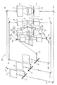
図5は、本発明の脆性材料基板の分断方法を実施するめの実施の形態5の分断装置40を示す模式図であり、3点以上の多点ビームを脆性材料基板の表裏に照射することを特徴とするものである。
【0055】
この分断装置40は、上記の図1に示す実施の形態1の分断装置1と概略同一の構成を有するものであり、図1の分断装置1の構成に加えて、冷却ノズル6から冷却媒体を吹き付けることによる冷却領域Bのさらに後方に、第二加熱領域を形成するための構成を追加したものである。したがって、以下の実施の形態5の分断装置の説明では、図1に示す分断装置1と同一の構成については、同一の参照符号を付して、詳しい説明は省略し、異なる構成についてのみ説明する。
【0056】
本実施の形態5の分断装置40では、第二レーザービームを発振する第二レーザービーム発振装置41を有している。この第二レーザービーム発振装置41から発振される第二レーザービームは、前方側での引張り応力の発生により形成された垂直クラックに対して、さらに、冷却領域Bの後方側に第二の加熱領域を形成することにより、その位置にも引張り応力を発生されることにより、前方側にて形成された垂直クラックを脆性材料基板の厚み方向にさらに深く形成するために用いられるものである。このため、第二レーザービーム発振装置41から発振される第二レーザービームのエネルギーは、レーザビーム発振装置2から発振されるレーザビームのエネルギーと同程度とされてもよいが、分断対象となる脆性材料基板の厚さ、硬度の相違により、レーザビームのエネルギーよりも高エネルギーとするか、低エネルギーとするかは、適宜設定される。
【0057】
この第二レーザービーム発振装置41の第二レーザービーム出射側には、発振された第二レーザービームの出力を分割するビームスピリッター42が設けられている。
【0058】
脆性材料基板Sの表裏のそれぞれの側には、冷却ノズル6の設置位置のさらに後方側になるように、第二レーザースポット形成装置43が設けられている。この第二レーザースポット形成装置43は、さらに、右側レーザースポット形成装置43aと左側レーザースポット形成装置43bとから構成されている。この右側及び左側レーザースポット形成装置43a及び43bのそれぞれは、スクライブ予定ラインを中心軸として、スクライブ予定ラインに対して左右対称になるように設けられている。ビームスプリッター42と、右側及び左側レーザースポット形成装置43a及び43bとの間には、第二のビームスプリッター44がそれぞれ設けられており、ビームスプリッター42により分離された第二レーザービームがさらに分割されるようになっている。第二ビームスプリッター44にて分離されたそれぞれの第二レーザービームは、ミラー等のビーム反射手段45によって、右側及び左側レーザスポット形成装置43a及び43bに導かれるようになっている。脆性材料基板Sの表裏のそれぞれの側に設けられた右側及び左側レーザースポット形成装置43a及び43bは、入射された第二レーザービームを所望の形状に調節する。右側及び左側レーザースポット形成装置43a及び43bから出射された第二レーザービームは、スクライブライン上に照射されるように調整されている。右側及び左側レーザースポット形成装置43a及び43bによりそれぞれ形成されるレーザースポットの形状は、既に形成された垂直クラックをさらに深く形成することが目的であるため、任意の形状でよい。例えば、図5に示す例では、スクライブラインに沿って長い長円形状に形成されている。
【0059】
次いで、脆性材料基板Sの分断方法について説明する。この分断方法についても、図1に示す分断装置1を用いた方法と概略同様であるので共通する方法については詳しい説明は省略する。
【0060】
この実施の形態5では、右側及び左側レーザースポット形成装置43a及び43bにより、冷却ノズル6から吹き出されることにより形成された冷却領域Bの後方側に第二の加熱領域を形成する。これにより、前方のレーザースポットによる加熱領域と冷却媒体吹き付けにより形成された冷却領域とによる熱応力により既に形成されたスクライブラインに沿う垂直クラックに対して、左右両側から、引張り応力を発生させて、より深い垂直クラックを脆性材料基板Sの厚み方向に進展させることが可能となる。
【0061】
このため、実施の形態2と比較して、相対速度を速くしてスクライブラインを形成させることができ、スクライブラインの形成を脆性材料基板Sの両面から実施するので、1回のスクライブ工程にて、垂直クラックが脆性材料基板Sの表裏を貫通した状態とすることができる。脆性材料基板が貼り合わせ脆性材料基板の場合は、上下の脆性材料基板を貫通する垂直クラックを得ることができ、1回のスクライブ工程にて貼り合わせ脆性材料基板を分断することができる。
(実施の形態6)
図6は、本発明の脆性材料基板の分断方法を実施するための実施の形態6の分断装置を示す模式図であり、3点以上の多点ビームを脆性材料基板の表裏に照射することを特徴とするものである。
【0062】
この分断装置50は、上記の図5に示す実施の形態5の分断装置40と概略同一の構成を有するものであり、図5の分断装置40の構成に加えて、レーザービームを照射することによる加熱領域のさらに前方に、余熱領域を形成するための構成を追加する構成を追加したものである。レーザービームを照射することによる加熱領域のさらに前方に、余熱領域を形成するための構成は、上述の実施の形態2に詳述されている。すなわち、本実施の形態6の分断装置50は、図5に示す分断装置40に、実施の形態2の構成を組み合わせて加えた構成となっているので、上述の実施の形態2及び5の分断装置と同一の構成については、同一の参照符号を付して、詳しい説明は省略する。
【0063】
本実施の形態6の分断装置50では、実施の形態2の分断装置10と同様に、余熱スポット形成装置13により、レーザスポット形成装置4により形成される加熱領域Aのさらに前方側に余熱領域Cを形成する。これにより、レーザスポット形成装置4からレーザービームが照射されても、予め、余熱領域Cが形成されているので、脆性材料基板Sが急激に温度上昇することを避けることができ、所望でない方向のクラックが発生することを避けることができる。また、レーザビームによる加熱を円滑に行うことができるので、レーザビームによる加熱領域を、脆性材料基板Sの厚み方向により深く形成することが可能になる。
【0064】
また、実施の形態5の分断装置40と同様に、右側及び左側レーザースポット形成装置43a及び43bにより、冷却ノズル6から吹き出されることにより形成された冷却領域Bの後方側に第二の加熱領域を形成する。これにより、前方のレーザースポットによる加熱領域と冷却媒体吹き付けにより形成された冷却領域とによる熱応力により既に形成されたスクライブラインに沿う垂直クラックに対して、左右両側から引張り応力を発生させて、垂直クラックを脆性材料基板の厚み方向に進展させることが可能となる。
【0065】
このため、実施の形態2と比較して、相対速度を速くしてスクライブラインを形成させることができ、スクライブラインの形成を脆性材料基板Sの両面から実施するので、1回のスクライブ工程にて、垂直クラックが脆性材料基板Sの表裏を貫通した状態とすることができる。脆性材料基板が貼り合わせ脆性材料基板の場合は、上下の脆性材料基板を貫通する垂直クラックを得ることができ、1回のスクライブ工程にて貼り合わせ脆性材料基板を分断することができる。
【0066】
したがって、本実施の形態6の分断装置では、上記の実施の形態2及び5の分断装置に比較して、さらに、分断面の品質が優れた脆性材料基板の分断を実施することが可能になる。
【0067】
なお、脆性材料基板の単板として、ガラス基板、石英、サファイヤ基板、半導体ウエハ、セラミックス等に、本発明の分断方法及び分断装置が適用され、貼り合わせ脆性材料基板として、フラットパネルディスプレイの一種である液晶表示基板、プラズマディスプレイパネル基板、有機EL基板、無機EL基板等の製造に本発明の分断方法及び分断装置が適用される。さらに、透過型プロジェクタ基板、反射型プロジェクタ基板等の製造にも本発明の分断方法及び分断装置が適用される。
【0068】
【発明の効果】
以上説明したように、本発明は、脆性材料基板の表面および裏面における相互に対応するように形成されるスクライブ予定ラインに沿って、該脆性材料基板の軟化点より低い温度でそれぞれ連続して同時に加熱して、加熱領域をそれぞれ形成しつつ、各加熱領域の近傍に冷却領域をそれぞれ連続して形成することにより、脆性材料基板の表面および裏面から該脆性材料基板を貫通する垂直クラックを形成して、該脆性材料基板を分断することを特徴とする。本発明では、脆性材料基板の両面に対してスクライブ工程を実施することにより、1回のスクライブ工程により脆性材料基板を垂直クラックが貫通したフルボディカットして、脆性材料基板が分断された状態とすることにより、従来方法において実施されていたスクライブ工程に続くブレイク工程を省略することができる。これにより、脆性材料基板を分断するための工程数を低減することができる。さらに、特に、貼り合わせ脆性材料基板を分断する場合には、貼り合わせ脆性材料基板の一対の脆性材料基板のそれぞれに対して行ってきたスクライブ工程及びブレイク工程のうちブレイク工程を省略することができるので、これに関連して、スクライブ工程からブレイク工程への搬送及び脆性材料基板の反転を行う必要がないので、脆性材料基板の搬送及び反転途中で脆性材料基板が落下する等のおそれを防止することができる。この結果、脆性材料基板の分断の歩留まりを向上することが可能になる。
【図面の簡単な説明】
【図1】実施の形態1の分断装置1を示す模式図である。
【図2】実施の形態2の分断装置10を示す模式図である。
【図3】実施の形態3の分断装置20を示す模式図である。
【図4】実施の形態4の分断装置30を示す模式図である。
【図5】実施の形態5の分断装置40を示す模式図である。
【図6】実施の形態6の分断装置50を示す模式図である。
【図7】レーザービーム照射を用いた脆性材料基板の分断方法を説明する模式図である。
【符号の説明】
1 分断装置
2 レーザービーム発振装置
3 ビームスプリッター
4 レーザスポット形成装置
5 ビーム反射手段
6 冷却ノズル
10 分断装置
11 余熱ビーム発振装置
12 ビームスプリッター
13 余熱スポット形成装置
14 ビーム反射手段
20 分断装置
21 第二レーザービーム発振装置
22 ビームスプリッター
23 第二レーザスポット形成装置
30 分断装置
40 分断装置
41 第二レーザービーム発振装置
42 ビームスプリッター
43 第二レーザースポット形成装置
44 第二ビームスプリッター
45 ビーム反射手段[0001]
BACKGROUND OF THE INVENTION
The present invention relates to a method for cutting a brittle material substrate such as a glass substrate used in a display device such as a liquid crystal display device, and a cutting device used for carrying out the cutting method.
[0002]
The brittle material substrate described in this specification includes a bonded brittle material substrate obtained by bonding a glass substrate or the like.
[0003]
[Prior art]
In order to cut a brittle material substrate typified by a glass substrate or the like, a scribing process for forming a scribe line in which vertical cracks, which are cracks formed at a predetermined depth from the surface on the brittle material substrate, are continued in a desired direction. And, following this scribing process, a break process for dividing the brittle material substrate along a scribe line formed in the scribing process by applying a pressing force to the brittle material substrate is generally performed. It has become a method.
[0004]
In a scribing process performed when a brittle material substrate is cut, a method of forming a scribe line using a wheel cutter made of cemented carbide or sintered diamond is known. However, in the method using such a wheel cutter, the cullet generated during the formation of the scribe line may adhere to the surface of the brittle material substrate, which causes display defects when used in a display device or the like. Moreover, when performing the break process which divides | segments a brittle material board | substrate, an undesired chip | tip may arise in the end surface part of a brittle material board | substrate, and there exists a possibility that the quality of the brittle material board | substrate after division | segmentation may become defective.
[0005]
On the other hand, in recent years, a method of forming a scribe line using a laser beam has been put into practical use. In the method of forming a scribe line using this laser beam, the laser beam LB is irradiated from the
[0006]
Further, a cooling medium such as cooling water is sprayed from the
[0007]
In the method of forming a scribe line using the laser beam as described above, the occurrence of cullet is extremely small, and thermal strain stress is used to form the scribe line. Chipping is difficult to occur.
[0008]
[Problems to be solved by the invention]
When the brittle material substrate to be divided is a single plate configured in a single plate shape, a scribe line is formed after performing the scribing process using the laser beam on one side of the brittle material substrate. After flipping the front and back of the brittle material substrate so that the back surface on which the scribe line is not formed is on the upper side, the scribe line and the back surface on the opposite side to the side on which the scribe line is formed A single brittle material substrate is divided by performing a breaking process in which a pressing force is applied along the opposing lines.
[0009]
In this case, the brittle material substrate can be surely divided in the break process following the scribe process, and in order to obtain a good sectional surface, the vertical crack of the scribe line formed in the scribe process is It is preferable to form deeply. However, when the vertical crack is deep, before carrying out the breaking process, when the brittle material substrate is transported and the front and back are reversed, the brittle material substrate is in a divided state, and the divided brittle material substrate is scribed. There is a possibility that it will be left in the apparatus for carrying out the process, and there is also a possibility that the brittle material substrate may fall during transportation.
[0010]
On the other hand, when the brittle material substrate to be divided is a bonded brittle material substrate formed by bonding a pair of brittle material substrates for use in a liquid crystal display device or the like, a pair of bonded brittle material substrates Since it is necessary to carry out a scribing process and a breaking process for each of these, the process for dividing is multi-step compared to a single plate, and each process is carried out, so that the brittle material substrate is transported and reversed Must be repeated.
[0011]
Therefore, when a bonded brittle material substrate, which is a type of brittle material substrate, is divided, the process for carrying out the division takes many steps, and the brittle material substrate is transferred and reversed each time each step is completed. Therefore, there is a higher risk that problems such as dropping of the brittle material substrate will occur during the transfer as compared with the case of a single plate.
[0012]
Therefore, regardless of whether the brittle material substrate to be divided is a single plate or a bonded substrate, the brittle material substrate is divided during the conveyance of the substrate after the scribing process, and falls to damage the substrate. There is a problem that the yield decreases.
[0013]
The present invention has been made to solve the above-described problems, and is capable of reducing the number of steps and improving the yield of the product, and a method for dividing a brittle material substrate and the method for dividing the same. An object is to provide a cutting device.
[0014]
[Means for Solving the Problems]
In order to solve the above-described problem, the brittle material substrate cutting method according to the present invention is based on the softening point of the brittle material substrate along the scribe lines formed so as to correspond to each other on the front surface and the back surface of the brittle material substrate. The brittle material substrate is formed from the front surface and the back surface of the brittle material substrate by continuously heating each at a low temperature and simultaneously forming a heating region, and continuously forming a cooling region in the vicinity of each heating region. The brittle material substrate is divided by forming vertical cracks penetrating through the substrate.
[0015]
In addition, the brittle material substrate cutting apparatus of the present invention includes a heating means for heating the brittle material substrate at a temperature lower than the softening point of the brittle material substrate to form a heating region, and cooling and cooling a position near the heating region. The cooling means for forming the region are respectively disposed on the front and back surfaces of the brittle material substrate to be divided so as to correspond to each other and to be relatively movable in a predetermined scribe line direction. The vertical stress that pierces the brittle material substrate from both sides of the brittle material substrate and divides the brittle material substrate is formed by the thermal stress formed by the heating region and the cooling region. To do.
[0016]
In the brittle material substrate cutting apparatus of the present invention, it is preferable that preheating means for preheating the front of the heating region is further provided.
[0017]
In the brittle material substrate cutting apparatus of the present invention, it is preferable that a second heating means for heating the rear of the cooling region is further provided.
[0018]
In the brittle material substrate cutting apparatus according to the present invention, it is preferable that the second heating unit is configured to be separated into two so that the direction along the scribe line is a symmetrical axis.
[0019]
DETAILED DESCRIPTION OF THE INVENTION
Hereinafter, the cutting method of the brittle material substrate of the present invention and the cutting device used for the cutting method will be described in detail.
[0020]
The method for dividing a brittle material substrate according to the present invention is characterized in that a scribing process is performed in which both the front and back surfaces of the brittle material substrate are simultaneously irradiated with a laser beam and sprayed with a cooling medium in the same direction. In the method for dividing a brittle material substrate according to the present invention, by performing a scribing process on both sides of the brittle material substrate, a full body cut in which vertical cracks penetrate the upper and lower surfaces of the brittle material substrate in one scribing process. In this state, the brittle material substrate is completely divided, and the break process following the scribe process performed in the conventional method can be omitted. Thereby, the number of processes for dividing a brittle material substrate can be reduced. Further, particularly when the bonded brittle material substrate, which is a kind of brittle material substrate, is divided, among the scribing process and the breaking process performed for each of the pair of brittle material substrates of the bonded brittle material substrate Since the break process can be omitted, there is no need to transfer the brittle material substrate from the scribe process to the break process and to reverse the brittle material substrate. The fear of falling etc. can be prevented. As a result, it becomes possible to improve the cutting yield of the brittle material substrate.
[0021]
Next, a specific cutting apparatus for carrying out the brittle material substrate cutting method of the present invention will be described with reference to the drawings in the following embodiments.
[0022]
(Embodiment 1)
FIG. 1 is a schematic diagram showing a cutting apparatus 1 for carrying out the method for cutting a brittle material substrate according to the first embodiment, which is characterized by irradiating the front and back of a brittle material substrate S with a single beam. is there.
[0023]
The cutting device 1 has a laser
[0024]
A laser spot forming device 4 is provided on each of the front and back sides of the brittle material substrate S so as to be symmetric with respect to the brittle material substrate S. Between the beam splitter 3 and each laser spot forming device 4, a beam reflecting means 5 such as a mirror is provided at an appropriate position in each place, and each laser spot forming device 4 is separated by the beam splitter 3. Each laser beam is incident. The laser spot forming device 4 provided on each of the front and back sides of the brittle material substrate S converts the incident laser beam into a desired shape, for example, a long oval shape along a scribe line. adjust.
[0025]
Each laser spot forming device 4 is movable relative to the brittle material substrate S in a fixed direction while maintaining a symmetrical relationship with the brittle material substrate S. Here, “relatively movable” means that when the laser spot forming device 4 is fixed and the brittle material substrate S is moved, or when the brittle material substrate S is fixed and the laser spot forming device 4 is moved, May move both the brittle material substrate S and the laser spot forming apparatus 4 together.
[0026]
Further, on each of the front and back surfaces of the brittle material substrate S, cooling
[0027]
Next, a method for cutting the brittle material substrate S using the cutting apparatus 1 having the above configuration will be described.
[0028]
When the laser
[0029]
Here, the heating temperature of the heating regions formed on the front and back surfaces of the brittle material substrate S prevents the front and back surfaces of the brittle material substrate S irradiated with the laser beam from melting. The temperature is lower than the melting temperature, that is, lower than the softening point of the brittle material substrate S.
[0030]
From the cooling
[0031]
In addition, cuts are formed at end positions of the scribe lines on the front and back surfaces of the brittle material substrate S to be divided by mechanical means (not shown) such as a cutter wheel or optical means such as a YAG laser. . Compressive stress is generated in the heating region by laser beam irradiation formed on the front and back surfaces of the brittle material substrate S, and tensile stress is generated in the cooling region to which the cooling medium is sprayed. The compressive stress caused by the laser beam irradiation and the tensile stress in the cooling region due to the cooling medium formed behind the laser beam are formed on the scribe line on the brittle material substrate S, and the heating region and the cooling region are scheduled to be scribed. By sequentially moving on the line, cracks in the vertical direction are continuously formed from the cuts formed in advance at the end of the brittle material substrate S, and a desired scribe line is formed.
[0032]
In the first embodiment, such a scribe line is formed from both sides of the brittle material substrate S, so that the vertical crack penetrates the front and back of the brittle material substrate S in one scribing process. Can do. When the brittle material substrate is a bonded brittle material substrate, the upper and lower brittleness can be obtained by lowering the moving speed of the laser spot A and the cooling spot B with respect to the brittle material substrate S (hereinafter referred to as relative speed). Vertical cracks penetrating the material substrate can be obtained, and the bonded brittle material substrate can be divided by a single scribing process. Therefore, it is not necessary to carry out the breaking process that has been conventionally performed following the scribing process, and the number of processes for dividing the brittle material substrate S can be reduced. In addition, it is possible to avoid problems such as dropping of the brittle material substrate S, which has occurred when the brittle material substrate S is transported and reversed in accordance with each step, and the yield can be improved. .
[0033]
(Embodiment 2)
FIG. 2 is a schematic view showing a cutting
[0034]
This cutting
[0035]
The cutting apparatus according to the second embodiment includes a residual
[0036]
A
[0037]
A preheating
[0038]
Next, a method for dividing the brittle material substrate S will be described. Since this cutting method is also substantially the same as the method using the cutting apparatus shown in FIG. 1, detailed description of common methods is omitted.
[0039]
In the second embodiment, the residual heat
[0040]
(Embodiment 3)
FIG. 3 is a schematic diagram showing a cutting
[0041]
The cutting
[0042]
The cutting device according to the third embodiment includes a second laser
[0043]
On the second laser beam emitting side of the second laser
[0044]
A second laser
[0045]
Next, a method for dividing the brittle material substrate S will be described. Since this cutting method is also substantially the same as the method using the cutting apparatus shown in FIG. 1, detailed description of common methods is omitted.
[0046]
In this third embodiment, the second laser
[0047]
Therefore, the scribe line can be formed at a higher relative speed than in the second embodiment, and the scribe line is formed from both sides of the brittle material substrate S. The vertical cracks can penetrate the front and back of the brittle material substrate S. When the brittle material substrate is a bonded brittle material substrate, vertical cracks penetrating the upper and lower brittle material substrates can be obtained, and the bonded brittle material substrate can be divided in one scribing process.
[0048]
(Embodiment 4)
FIG. 4 is a schematic diagram showing a cutting
[0049]
This cutting
[0050]
In the
[0051]
Similarly to the
[0052]
Therefore, the scribe line can be formed at a higher relative speed than in the second embodiment, and the scribe line is formed from both sides of the brittle material substrate S. The vertical cracks can penetrate the front and back of the brittle material substrate S. When the brittle material substrate is a bonded brittle material substrate, vertical cracks penetrating the upper and lower brittle material substrates can be obtained, and the bonded brittle material substrate can be divided in one scribing process.
[0053]
Therefore, in the cutting apparatus according to the fourth embodiment, it is possible to further cut the brittle material substrate having superior divided cross section quality as compared with the cutting apparatuses according to the first to third embodiments. .
[0054]
(Embodiment 5)
FIG. 5 is a schematic view showing a cutting
[0055]
This cutting
[0056]
The cutting
[0057]
On the second laser beam emitting side of the second laser
[0058]
A second laser
[0059]
Next, a method for dividing the brittle material substrate S will be described. Since this cutting method is also substantially the same as the method using the cutting apparatus 1 shown in FIG. 1, detailed description of common methods is omitted.
[0060]
In the fifth embodiment, the second heating region is formed on the rear side of the cooling region B formed by blowing from the cooling
[0061]
Therefore, the scribe line can be formed at a higher relative speed than in the second embodiment, and the scribe line is formed from both sides of the brittle material substrate S. The vertical cracks can penetrate the front and back of the brittle material substrate S. When the brittle material substrate is a bonded brittle material substrate, vertical cracks penetrating the upper and lower brittle material substrates can be obtained, and the bonded brittle material substrate can be divided in one scribing process.
(Embodiment 6)
FIG. 6 is a schematic diagram showing a cutting apparatus according to a sixth embodiment for carrying out the method for cutting a brittle material substrate according to the present invention, and irradiating the front and back of the brittle material substrate with three or more multi-point beams. It is a feature.
[0062]
This cutting
[0063]
In the
[0064]
Further, similarly to the
[0065]
Therefore, the scribe line can be formed at a higher relative speed than in the second embodiment, and the scribe line is formed from both sides of the brittle material substrate S. The vertical cracks can penetrate the front and back of the brittle material substrate S. When the brittle material substrate is a bonded brittle material substrate, vertical cracks penetrating the upper and lower brittle material substrates can be obtained, and the bonded brittle material substrate can be divided in one scribing process.
[0066]
Therefore, in the cutting apparatus according to the sixth embodiment, it is possible to further cut the brittle material substrate, which is superior in the quality of the cross section, as compared with the cutting apparatuses according to the second and fifth embodiments. .
[0067]
Note that the cutting method and the cutting apparatus of the present invention are applied to a glass substrate, quartz, sapphire substrate, semiconductor wafer, ceramics, etc. as a single plate of a brittle material substrate, and as a bonded brittle material substrate, it is a kind of flat panel display. The cutting method and the cutting apparatus of the present invention are applied to the production of a certain liquid crystal display substrate, plasma display panel substrate, organic EL substrate, inorganic EL substrate and the like. Furthermore, the cutting method and the cutting apparatus of the present invention are applied to the manufacture of a transmissive projector substrate, a reflective projector substrate, and the like.
[0068]
【The invention's effect】
As described above, according to the present invention, each of the brittle material substrates can be simultaneously and continuously performed along the planned scribe lines formed on the front and back surfaces of the brittle material substrate at temperatures lower than the softening point of the brittle material substrate. By forming each heating region by heating and forming a cooling region continuously in the vicinity of each heating region, vertical cracks penetrating the brittle material substrate from the front and back surfaces of the brittle material substrate are formed. Then, the brittle material substrate is divided. In the present invention, by carrying out a scribing process on both surfaces of the brittle material substrate, a full body cut through the vertical cracks through the brittle material substrate by one scribing process, and the brittle material substrate is divided. By doing so, the break process following the scribe process performed in the conventional method can be omitted. Thereby, the number of processes for dividing a brittle material substrate can be reduced. Further, particularly when the bonded brittle material substrate is divided, the breaking step can be omitted among the scribing process and the breaking process performed on each of the pair of brittle material substrates of the bonded brittle material substrate. Therefore, there is no need to transfer from the scribing process to the breaking process and inversion of the brittle material substrate in this connection, thus preventing the possibility of the brittle material substrate falling during the conveyance and inversion of the brittle material substrate. be able to. As a result, it becomes possible to improve the cutting yield of the brittle material substrate.
[Brief description of the drawings]
FIG. 1 is a schematic diagram showing a cutting apparatus 1 according to a first embodiment.
FIG. 2 is a schematic diagram showing a cutting
FIG. 3 is a schematic diagram showing a cutting
FIG. 4 is a schematic diagram showing a
FIG. 5 is a schematic diagram showing a
FIG. 6 is a schematic diagram showing a cutting
FIG. 7 is a schematic diagram for explaining a method of dividing a brittle material substrate using laser beam irradiation.
[Explanation of symbols]
1 Cutting device
2 Laser beam oscillator
3 Beam splitter
4 Laser spot forming device
5 Beam reflection means
6 Cooling nozzle
10 cutting device
11 Residual heat beam oscillator
12 Beam splitter
13 Heating spot forming device
14 Beam reflection means
20 cutting device
21 Second laser beam oscillator
22 Beam splitter
23 Second laser spot forming apparatus
30 cutting device
40 cutting device
41 Second laser beam oscillator
42 Beam splitter
43 Second laser spot forming device
44 Second beam splitter
45 Beam reflection means
Claims (5)
Priority Applications (1)
| Application Number | Priority Date | Filing Date | Title |
|---|---|---|---|
| JP2002193919A JP2004035315A (en) | 2002-07-02 | 2002-07-02 | Method and apparatus for dividing brittle material substrates |
Applications Claiming Priority (1)
| Application Number | Priority Date | Filing Date | Title |
|---|---|---|---|
| JP2002193919A JP2004035315A (en) | 2002-07-02 | 2002-07-02 | Method and apparatus for dividing brittle material substrates |
Publications (2)
| Publication Number | Publication Date |
|---|---|
| JP2004035315A true JP2004035315A (en) | 2004-02-05 |
| JP2004035315A5 JP2004035315A5 (en) | 2005-10-20 |
Family
ID=31702779
Family Applications (1)
| Application Number | Title | Priority Date | Filing Date |
|---|---|---|---|
| JP2002193919A Pending JP2004035315A (en) | 2002-07-02 | 2002-07-02 | Method and apparatus for dividing brittle material substrates |
Country Status (1)
| Country | Link |
|---|---|
| JP (1) | JP2004035315A (en) |
Cited By (11)
| Publication number | Priority date | Publication date | Assignee | Title |
|---|---|---|---|---|
| KR100656397B1 (en) * | 2005-01-07 | 2006-12-13 | 엘지전자 주식회사 | Glass cutting device for flat panel display |
| JP2007043100A (en) * | 2005-06-30 | 2007-02-15 | Semiconductor Energy Lab Co Ltd | Method for fabricating semiconductor device |
| JP2008246808A (en) * | 2007-03-30 | 2008-10-16 | Japan Steel Works Ltd:The | Processing method for workpiece made of high brittle non-metal material and device thereof |
| JP2009504432A (en) * | 2005-08-06 | 2009-02-05 | イェーノプティク アウトマティジールングステヒニーク ゲゼルシャフト ミット ベシュレンクテル ハフツング | A method of tearing a fragile flat member with a laser beam using a previously created trace |
| JP2010067350A (en) * | 2008-09-08 | 2010-03-25 | Hitachi Displays Ltd | Organic el display device and its manufacturing method |
| KR101010125B1 (en) * | 2004-03-31 | 2011-01-24 | 엘지디스플레이 주식회사 | Apparatus for cutting substrate and method for cutting thereof |
| US8710403B2 (en) * | 2008-02-19 | 2014-04-29 | M-Solv Ltd. | Laser processing a multi-device panel |
| CN103831527A (en) * | 2014-02-28 | 2014-06-04 | 华中科技大学 | Method and device for quickly separating optical crystals by using laser light |
| WO2014175146A1 (en) * | 2013-04-26 | 2014-10-30 | 旭硝子株式会社 | Method for cutting glass plate |
| WO2014175147A1 (en) * | 2013-04-26 | 2014-10-30 | 旭硝子株式会社 | Method for cutting glass plate |
| CN114274384A (en) * | 2021-12-24 | 2022-04-05 | 唐山国芯晶源电子有限公司 | Quartz wafer cutting process method |
-
2002
- 2002-07-02 JP JP2002193919A patent/JP2004035315A/en active Pending
Cited By (13)
| Publication number | Priority date | Publication date | Assignee | Title |
|---|---|---|---|---|
| KR101010125B1 (en) * | 2004-03-31 | 2011-01-24 | 엘지디스플레이 주식회사 | Apparatus for cutting substrate and method for cutting thereof |
| KR100656397B1 (en) * | 2005-01-07 | 2006-12-13 | 엘지전자 주식회사 | Glass cutting device for flat panel display |
| JP2007043100A (en) * | 2005-06-30 | 2007-02-15 | Semiconductor Energy Lab Co Ltd | Method for fabricating semiconductor device |
| KR101323078B1 (en) * | 2005-08-06 | 2013-10-29 | 예놉틱 아우토마티지어룽스테히닉 게엠베하 | Method for servering brittle flat material by laser beam, with traces produced prior to separation |
| JP2009504432A (en) * | 2005-08-06 | 2009-02-05 | イェーノプティク アウトマティジールングステヒニーク ゲゼルシャフト ミット ベシュレンクテル ハフツング | A method of tearing a fragile flat member with a laser beam using a previously created trace |
| JP2008246808A (en) * | 2007-03-30 | 2008-10-16 | Japan Steel Works Ltd:The | Processing method for workpiece made of high brittle non-metal material and device thereof |
| US8710403B2 (en) * | 2008-02-19 | 2014-04-29 | M-Solv Ltd. | Laser processing a multi-device panel |
| JP2010067350A (en) * | 2008-09-08 | 2010-03-25 | Hitachi Displays Ltd | Organic el display device and its manufacturing method |
| WO2014175146A1 (en) * | 2013-04-26 | 2014-10-30 | 旭硝子株式会社 | Method for cutting glass plate |
| WO2014175147A1 (en) * | 2013-04-26 | 2014-10-30 | 旭硝子株式会社 | Method for cutting glass plate |
| CN103831527A (en) * | 2014-02-28 | 2014-06-04 | 华中科技大学 | Method and device for quickly separating optical crystals by using laser light |
| CN103831527B (en) * | 2014-02-28 | 2016-01-20 | 华中科技大学 | A kind of laser quick separating optical crystal method and device |
| CN114274384A (en) * | 2021-12-24 | 2022-04-05 | 唐山国芯晶源电子有限公司 | Quartz wafer cutting process method |
Similar Documents
| Publication | Publication Date | Title |
|---|---|---|
| JP4156513B2 (en) | Scribing method and scribing apparatus for brittle material substrate | |
| US11053156B2 (en) | Method of closed form release for brittle materials using burst ultrafast laser pulses | |
| JP5113462B2 (en) | Method for chamfering a brittle material substrate | |
| KR100849696B1 (en) | Brittle material scribing method and scribing apparatus | |
| JP5345334B2 (en) | Thermal stress cleaving method for brittle materials | |
| JP3787073B2 (en) | Method and apparatus for cutting non-metal substrate using laser beam | |
| JP4337050B2 (en) | Glass plate cutting device {GLASS-PLATECHTINGMACHINE} | |
| US6713720B2 (en) | Method for cutting a non-metallic substrate | |
| JP5325209B2 (en) | Processing method of brittle material substrate | |
| JP5887929B2 (en) | Method for dividing workpiece and method for dividing substrate with optical element pattern | |
| JP2005132694A (en) | Glass cutting method | |
| KR100551526B1 (en) | Device and method for scribing fragile material substrate | |
| JP2011230940A (en) | Cutting method for brittle material substrate | |
| TW201334904A (en) | Splitting method of processed object and splitting method of substrate having optical element pattern | |
| WO2010071128A1 (en) | Splitting apparatus and cleavage method for brittle material | |
| JP2009040665A (en) | Full body cutting method of brittle material | |
| KR100647454B1 (en) | Device and method for scribing substrate of brittle material | |
| JP2004035315A (en) | Method and apparatus for dividing brittle material substrates | |
| JP2005212364A (en) | Fracturing system of brittle material and method thereof | |
| WO2004014625A1 (en) | Method and device for scribing fragile material substrate | |
| TWI292352B (en) | ||
| JP2007301631A (en) | Cleaving apparatus and cleaving method | |
| JP2009107304A (en) | Thermal stress cutting method for brittle material | |
| JP5444158B2 (en) | Cleaving method of brittle material substrate | |
| JP2009262408A (en) | Method for scribing brittle material substrate and device therefor |
Legal Events
| Date | Code | Title | Description |
|---|---|---|---|
| A521 | Written amendment |
Free format text: JAPANESE INTERMEDIATE CODE: A523 Effective date: 20050627 |
|
| A621 | Written request for application examination |
Free format text: JAPANESE INTERMEDIATE CODE: A621 Effective date: 20050627 |
|
| A977 | Report on retrieval |
Free format text: JAPANESE INTERMEDIATE CODE: A971007 Effective date: 20071109 |
|
| A131 | Notification of reasons for refusal |
Free format text: JAPANESE INTERMEDIATE CODE: A131 Effective date: 20080212 |
|
| A521 | Written amendment |
Free format text: JAPANESE INTERMEDIATE CODE: A523 Effective date: 20080407 |
|
| A02 | Decision of refusal |
Free format text: JAPANESE INTERMEDIATE CODE: A02 Effective date: 20080704 |
|
| A521 | Written amendment |
Free format text: JAPANESE INTERMEDIATE CODE: A523 Effective date: 20080902 |
|
| A911 | Transfer of reconsideration by examiner before appeal (zenchi) |
Free format text: JAPANESE INTERMEDIATE CODE: A911 Effective date: 20081023 |
|
| A912 | Removal of reconsideration by examiner before appeal (zenchi) |
Free format text: JAPANESE INTERMEDIATE CODE: A912 Effective date: 20081121 |
|
| A521 | Written amendment |
Free format text: JAPANESE INTERMEDIATE CODE: A523 Effective date: 20110817 |