JP2005212364A - Fracturing system of brittle material and method thereof - Google Patents
Fracturing system of brittle material and method thereof Download PDFInfo
- Publication number
- JP2005212364A JP2005212364A JP2004023636A JP2004023636A JP2005212364A JP 2005212364 A JP2005212364 A JP 2005212364A JP 2004023636 A JP2004023636 A JP 2004023636A JP 2004023636 A JP2004023636 A JP 2004023636A JP 2005212364 A JP2005212364 A JP 2005212364A
- Authority
- JP
- Japan
- Prior art keywords
- substrate
- processed
- cleaving
- unit
- cutting line
- Prior art date
- Legal status (The legal status is an assumption and is not a legal conclusion. Google has not performed a legal analysis and makes no representation as to the accuracy of the status listed.)
- Pending
Links
Images


Abstract
Description
本発明は、脆性材料(硬く脆い材料)からなる被加工基板を局部的に加熱し、その熱応力によって当該被加工基板に亀裂を生じさせて割断加工を行う割断加工システムに係り、とりわけ、脆性材料の高品位でかつ高速な割断加工を実現することができる、脆性材料の割断加工システム及びその方法に関する。 The present invention relates to a cleaving system in which a substrate to be processed made of a brittle material (hard and brittle material) is locally heated, and the substrate to be processed is cracked by the thermal stress, and is particularly brittle. The present invention relates to a brittle material cleaving system and method capable of realizing high-quality and high-speed cleaving of a material.
従来から、脆性材料からなる被加工基板に対して割断加工を行う方法として、(a)ダイヤモンドなどの硬質材料を用いて被加工基板の表面を引っかくなどの作業を行って、被加工基板の表面に連続的でかつ微細な線状の亀裂や加工溝などを形成した後、その亀裂や加工溝などを拡げるように圧力または衝撃荷重を加えることにより被加工基板を割断する方法、(b)ダイヤモンド砥石などの研削砥石を用いて被加工基板の表面にスクライビング加工を施し、その加工線に沿って被加工基板を割断する方法が知られている。このうち、後者の(b)の方法は、液晶ディスプレイやプラズマディスプレイパネル(PDP)、フィールドエミッションディスプレイ(FED)などを製造するための製造プロセスにおいてガラス基板などを割断するために一般的に用いられている。 Conventionally, as a method of cleaving a work substrate made of a brittle material, (a) a surface of the work substrate is obtained by scratching the surface of the work substrate using a hard material such as diamond. A method of cleaving a substrate to be processed by forming a continuous and fine linear crack or processed groove on the substrate and then applying a pressure or impact load so as to expand the crack or processed groove; (b) Diamond A method is known in which a surface of a substrate to be processed is scribed using a grinding wheel such as a grindstone, and the substrate to be processed is cut along the processing line. Among these, the latter method (b) is generally used for cleaving glass substrates and the like in a manufacturing process for manufacturing a liquid crystal display, a plasma display panel (PDP), a field emission display (FED) and the like. ing.
しかしながら、上記(a)の方法では、被加工基板の割断面に応力集中の原因となる不規則な微細な亀裂が残存しやすく、割断加工を行った後に端面の研磨などの仕上げ加工が必要になるなどの問題がある。 However, in the above method (a), irregular fine cracks that cause stress concentration are likely to remain on the cut surface of the substrate to be processed, and finishing processing such as polishing of the end face is necessary after cleaving. There are problems such as becoming.
また、上記(b)の方法では、スクライビング加工を施すために加工しろが必要になるという問題がある。また、硬い脆性材料からなる被加工基板ではスクライビング加工を施すこと自体が難しいという問題もある。さらに、被加工基板の割断面の表面にバリなどの不規則な面が発生しやすく、質の高い加工面を形成するのが困難であるなどの問題もある。 Further, the method (b) has a problem in that a machining margin is required to perform the scribing process. In addition, there is a problem that it is difficult to perform a scribing process on a workpiece substrate made of a hard brittle material. Furthermore, there is a problem that irregular surfaces such as burrs are easily generated on the surface of the cut surface of the substrate to be processed, and it is difficult to form a high-quality processed surface.
特に、上記(b)の方法を利用して、液晶ディスプレイやプラズマディスプレイパネル、フィールドエミッションディスプレイなどに用いられるガラス基板を割断する場合には、(1)研削砥石などによってスクライビング加工を施すための刃の寿命が短い、(2)刃を交換する際の再調整に時間がかかり、製造プロセスを停止するための無駄な時間が必要になる、(3)被加工基板の割断面の表面に生じるバリやゴミなどを除去するための洗浄工程や仕上げのための研磨工程などが別途必要になる、(4)近年一般的になりつつある薄厚のガラス基板(例えば、0.1mm〜0.数mm程度の厚さの基板)に対しての割断が難しく、スクライビング加工中に破損やチッピングなどを生じるおそれがある、という問題がある。 In particular, when cleaving a glass substrate used for a liquid crystal display, a plasma display panel, a field emission display, etc. by using the method (b), (1) a blade for scribing with a grinding wheel (2) It takes time to readjust when replacing the blade, and wasteful time is required to stop the manufacturing process. (3) Burrs generated on the surface of the cut surface of the substrate to be processed (4) A thin glass substrate (for example, about 0.1 mm to about several millimeters) that is becoming common in recent years. (Thickness substrate) is difficult to cut, and there is a possibility that breakage or chipping may occur during scribing.
このような事情の下で、液晶ディスプレイやプラズマディスプレイパネル、フィールドエミッションディスプレイなどに用いられるガラス基板を割断する方法としては、(c)CO2レーザ(炭酸ガスレーザ)などのレーザビームを用いて脆性材料からなる被加工基板を局部的に加熱し、その熱応力によって当該被加工基板に亀裂を生じさせて割断する方法が提案されている(特許文献1〜5参照)。
Under such circumstances, as a method of cleaving a glass substrate used for a liquid crystal display, a plasma display panel, a field emission display, etc., (c) a brittle material using a laser beam such as a CO 2 laser (carbon dioxide laser) A method has been proposed in which a substrate to be processed is heated locally, and the substrate to be processed is cracked by the thermal stress (see
この(c)の方法では、ガラス基板を割断する場合でも、(1)研削砥石などを用いないことから刃の交換などに伴う問題がなく、(2)被加工基板の割断面の表面にバリやゴミなどが生じないことから洗浄工程や研磨工程などを省略することができ、さらに、(3)薄厚のガラス基板を割断する場合でも破損やチッピングなどが生じるおそれがない、という利点がある。
しかしながら、上記(c)の方法(レーザビームを用いて被加工基板を割断する方法)では、被加工基板に損傷(溶融や変形、変質など)を与えないという条件下でレーザビームの投入可能なエネルギーに制約があり、脆性材料の高品位な割断加工を高速に実現することが困難であった。具体的には例えば、1mmオーダの厚さのガラス基板では、表面割断(Micro Crack Method)(ガラス基板の表面のみを割断する方法)の場合にはその速度を数百mm/秒以下程度に抑え、全割断(Full Body Crack Method)(ガラス基板の表面から裏面までを貫通した状態で割断する方法)の場合にはその速度は数十mm/秒以下程度に抑える必要があった。 However, in the method (c) (a method of cleaving the substrate to be processed using a laser beam), the laser beam can be injected under the condition that the substrate to be processed is not damaged (melted, deformed, altered, etc.). Due to energy limitations, it was difficult to achieve high-quality cleaving of brittle materials at high speed. Specifically, for example, in the case of a glass substrate having a thickness on the order of 1 mm, in the case of surface cracking (micro crack method) (a method of cleaving only the surface of the glass substrate), the speed is suppressed to about several hundred mm / second or less. In the case of the Full Body Crack Method (a method of cleaving with the glass substrate penetrating from the front surface to the back surface), the speed has to be suppressed to about several tens of mm / second or less.
本発明はこのような点を考慮してなされたものであり、脆性材料の高品位でかつ高速な割断加工を実現することができる、脆性材料の割断加工システム及びその方法を提供することを目的とする。 The present invention has been made in consideration of such points, and an object of the present invention is to provide a brittle material cleaving system and method capable of realizing high-quality and high-speed cleaving of a brittle material. And
本発明は、第1の解決手段として、脆性材料からなる被加工基板を局部的に加熱し、その熱応力によって当該被加工基板に亀裂を生じさせて割断加工を行う割断加工システムにおいて、割断予定線に沿う方向に延びる線状の照射パターンを有するレーザビームを前記被加工基板上に照射して当該被加工基板を局部的に加熱する割断ユニットと、前記割断ユニットに対して前記被加工基板を相対的に移動させ、前記割断ユニットにより前記被加工基板上で局部的に加熱が行われる領域を前記割断予定線に沿って移動させる移動ユニットとを備え、前記割断ユニットにより前記被加工基板上に照射される前記レーザビームの照射パターンは、前記割断予定線に沿う方向に関して均一な強度分布を有することを特徴とする、脆性材料の割断加工システムを提供する。 As a first solution, the present invention provides a cleaving schedule in a cleaving system in which a substrate to be processed made of a brittle material is locally heated, and the substrate to be processed is cracked by the thermal stress. A cleaving unit that irradiates the substrate to be processed with a laser beam having a linear irradiation pattern extending in a direction along the line to locally heat the substrate to be processed, and the substrate to be processed with respect to the cleaving unit. A moving unit that moves the region that is heated locally on the substrate to be processed by the cleaving unit along the planned cutting line, and is arranged on the substrate to be processed by the cleaving unit. The irradiation pattern of the laser beam to be irradiated has a uniform intensity distribution in a direction along the planned cutting line, and the cutting processing system of the brittle material is characterized in that To provide a beam.
なお、上述した第1の解決手段において、前記割断ユニットにより前記被加工基板上に照射される前記レーザビームの照射パターンは、前記割断予定線に沿って基準ビームを所定の長さに亘って繰り返し走査することにより生成されることが好ましい。また、前記割断ユニットにより前記被加工基板上に照射される前記レーザビームの照射パターンのうち前記割断予定線に沿う方向の長さは前記被加工基板の厚さの10倍を越えることが好ましい。 In the first solving means described above, the irradiation pattern of the laser beam irradiated onto the substrate to be processed by the cleaving unit is such that the reference beam is repeated over a predetermined length along the planned cutting line. It is preferably generated by scanning. Moreover, it is preferable that the length of the irradiation pattern of the laser beam irradiated on the substrate to be processed by the cleaving unit in the direction along the planned cutting line exceeds 10 times the thickness of the substrate to be processed.
また、上述した第1の解決手段においては、前記割断ユニットにより前記被加工基板上で局部的に加熱が行われる領域を予熱して当該領域の温度を上昇させる予熱ユニットをさらに備えることが好ましい。ここで、前記予熱ユニットは、前記割断予定線に沿う方向に延びる線状の照射パターンであってその強度分布が前記割断予定線に沿う方向に関して均一である照射パターンを有するレーザビームを前記被加工基板上に照射して当該被加工基板を局部的に予熱することが好ましい。また、前記予熱ユニットにより前記被加工基板上に照射される前記レーザビームは、前記割断予定線に沿って基準ビームを所定の長さに亘って繰り返し走査することにより生成されることが好ましい。 Moreover, in the 1st solution means mentioned above, it is preferable to further provide the preheating unit which preheats the area | region where heating is locally performed on the said to-be-processed substrate by the said cleaving unit, and raises the temperature of the said area | region. Here, the preheating unit has a linear irradiation pattern extending in a direction along the planned cutting line, and a laser beam having an irradiation pattern whose intensity distribution is uniform with respect to the direction along the planned cutting line. It is preferable to preheat the substrate to be processed by irradiating the substrate. The laser beam irradiated onto the substrate to be processed by the preheating unit is preferably generated by repeatedly scanning a reference beam over a predetermined length along the planned cutting line.
さらに、上述した第1の解決手段においては、前記割断ユニットにより前記被加工基板上で局部的に加熱が行われた領域に冷却剤を吹き付けて当該領域を冷却する冷却ユニットをさらに備えることが好ましい。 Furthermore, in the first solving means described above, it is preferable to further include a cooling unit that sprays a coolant onto a region heated locally on the substrate to be processed by the cleaving unit to cool the region. .
本発明は、第2の解決手段として、脆性材料からなる被加工基板を局部的に加熱し、その熱応力によって当該被加工基板に亀裂を生じさせて割断加工を行う割断加工方法において、割断対象となる被加工基板を準備する準備工程と、割断予定線に沿う方向に延びる線状の照射パターンを有するレーザビームを前記被加工基板上に照射して当該被加工基板を局部的に加熱しつつ、当該被加工基板上で局部的に加熱が行われる領域を前記割断予定線に沿って移動させる割断工程とを含み、前記割断工程において前記被加工基板上に照射される前記レーザビームの照射パターンは、前記割断予定線に沿う方向に関して均一な強度分布を有することを特徴とする、脆性材料の割断加工方法を提供する。 As a second solution, the present invention provides a cleaving method in which a substrate to be processed made of a brittle material is locally heated and a crack is generated in the substrate to be processed by the thermal stress. A preparatory step for preparing a substrate to be processed, and a laser beam having a linear irradiation pattern extending in a direction along the planned cutting line is irradiated on the substrate to be heated while locally heating the substrate to be processed An irradiation pattern of the laser beam irradiated onto the substrate to be processed in the cleaving step, and a cleaving step of moving a region where heating is locally performed on the substrate to be processed along the planned cutting line Provides a method for cleaving a brittle material, characterized by having a uniform strength distribution in a direction along the planned cutting line.
なお、上述した第2の解決手段において、前記割断工程において前記被加工基板上に照射される前記レーザビームは、前記割断予定線に沿って基準ビームを所定の長さに亘って繰り返し走査することにより生成されることが好ましい。また、前記割断工程において前記被加工基板上に照射される前記レーザビームの照射パターンのうち前記割断予定線に沿う方向の長さは前記被加工基板の厚さの10倍を越えることが好ましい。 In the second solving means described above, the laser beam irradiated onto the substrate to be processed in the cleaving step repeatedly scans a reference beam over a predetermined length along the planned cutting line. It is preferable that it is produced | generated by. Moreover, it is preferable that the length of the irradiation pattern of the laser beam irradiated on the substrate to be processed in the cleaving step in the direction along the planned cutting line exceeds 10 times the thickness of the substrate to be processed.
また、上述した第2の解決手段においては、前記割断工程において前記被加工基板上で局部的に加熱が行われる領域を予熱して当該領域の温度を上昇させる予熱工程をさらに含むことが好ましい。ここで、前記予熱工程において、前記割断予定線に沿う方向に延びる線状の照射パターンであってその強度分布が前記割断予定線に沿う方向に関して均一である照射パターンを有するレーザビームを前記被加工基板上に照射して当該被加工基板を局部的に予熱することが好ましい。また、前記予熱工程において前記被加工基板上に照射される前記レーザビームは、前記割断予定線に沿って基準ビームを所定の長さに亘って繰り返し走査することにより生成されることが好ましい。 Further, the second solving means described above preferably further includes a preheating step of preheating a region where heating is locally performed on the substrate to be processed in the cleaving step to increase the temperature of the region. Here, in the preheating step, a laser beam having an irradiation pattern which is a linear irradiation pattern extending in a direction along the planned cutting line and whose intensity distribution is uniform in the direction along the predetermined cutting line is processed. It is preferable to preheat the substrate to be processed by irradiating the substrate. Further, it is preferable that the laser beam irradiated on the substrate to be processed in the preheating step is generated by repeatedly scanning a reference beam over a predetermined length along the planned cutting line.
さらに、上述した第2の解決手段においては、前記割断工程において前記被加工基板上で局部的に加熱が行われた領域に冷却剤を吹き付けて当該領域を冷却する冷却工程をさらに含むことが好ましい。 Furthermore, the second solving means described above preferably further includes a cooling step of cooling the region by spraying a coolant on the region heated locally on the workpiece substrate in the cleaving step. .
本発明によれば、割断予定線に沿う方向に延びる線状の照射パターンであってその強度分布が割断予定線に沿う方向に関して均一である照射パターンを有するレーザビームを被加工基板上に照射して当該被加工基板を局部的に加熱しつつ、当該被加工基板上で局部的に加熱が行われる領域を割断予定線に沿って移動させるようにしているので、被加工基板に損傷を与えない範囲で被加工基板に照射されるレーザビームのビーム強度を限界まで上げることができる。このため、ビーム強度がガウス分布をとる従来のレーザビームの場合に比べて、被加工基板の亀裂部分に対してより大きな熱応力(引張応力)を加えることができ、脆性材料のより高品位でかつ高速な割断加工を実現することができる。 According to the present invention, a processing target substrate is irradiated with a laser beam having a linear irradiation pattern extending in a direction along the planned cutting line, the intensity distribution of which is uniform in the direction along the planned cutting line. Since the region to be locally heated on the substrate to be processed is moved along the planned cutting line while locally heating the substrate to be processed, the substrate to be processed is not damaged. The beam intensity of the laser beam irradiated onto the substrate to be processed can be increased to the limit. For this reason, it is possible to apply a larger thermal stress (tensile stress) to the cracked portion of the substrate to be processed than in the case of a conventional laser beam having a Gaussian beam intensity. Moreover, high-speed cleaving can be realized.
また、本発明によれば、ビーム強度がガウス分布をとる従来のレーザビームの場合に比べて、被加工基板の亀裂部分に対してより大きな熱応力(引張応力)を加えることができるので、被加工基板として2枚のガラス基板がシール材を介して貼り合わされたような液晶基板が用いられる場合であっても高品位でかつ高速な割断加工を実現することができる。 In addition, according to the present invention, a larger thermal stress (tensile stress) can be applied to the cracked portion of the substrate to be processed than in the case of a conventional laser beam having a Gaussian beam intensity. Even when a liquid crystal substrate in which two glass substrates are bonded together with a sealing material is used as a processed substrate, high-quality and high-speed cleaving can be realized.
さらに、本発明によれば、被加工基板に対してレーザビームを照射することにより割断加工を行っているので、被加工基板の割断面の表面にバリやゴミなどが生じず、洗浄工程や仕上げのための研磨工程などを省略することができる。また、薄厚基板を割断する場合でも破損やチッピングなどが生じるおそれがない。 Furthermore, according to the present invention, since the cleaving process is performed by irradiating the substrate to be processed with a laser beam, the surface of the cut section of the substrate to be processed does not generate burrs or dust, and the cleaning process or finish The polishing process for the purpose can be omitted. Further, even when the thin substrate is cleaved, there is no risk of damage or chipping.
以下、図面を参照して本発明の実施の形態について説明する。 Embodiments of the present invention will be described below with reference to the drawings.
まず、図1により、本発明の一実施の形態に係る割断加工システムの全体構成について説明する。 First, the overall configuration of the cleaving system according to one embodiment of the present invention will be described with reference to FIG.
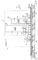
図1に示すように、割断加工システム1は、脆性材料からなる被加工基板60を局部的に加熱し、その熱応力によって被加工基板60に亀裂を生じさせて割断加工を行うものであり、被加工基板60に対して割断加工を行うための加工部ユニット5と、被加工基板60を支持するとともに加工部ユニット5に対して被加工基板60を相対的に移動させる移動ユニット50とを備えている。なおここでは、割断対象となる被加工基板60として、2枚のガラス基板(上基板61及び下基板62)がシール材(図示せず)を介して貼り合わされた液晶基板を用いるものとする。
As shown in FIG. 1, the
このうち、加工部ユニット5は、割断線リードユニット10、予熱ユニット20、割断ユニット30及び冷却ユニット40を含み、これらの各ユニットが被加工基板60上で割断予定線71に沿って相対的に移動するように構成されている。なお、割断線リードユニット10、予熱ユニット20、割断ユニット30及び冷却ユニット40は、被加工基板60上での移動方向に関して先頭側から後尾側へ向かってこの順番で一直線状に配置されている。
Among these, the
以下、割断線リードユニット10、予熱ユニット20、割断ユニット30及び冷却ユニット40の詳細について説明する。
The details of the cutting
割断線リードユニット10は、被加工基板60の表面に圧痕(微細なクラック)を形成するためのものであり、支持部材(図示せず)に固定された固定部11と、固定部11に対して上下方向(Z方向)に相対的に移動する可動部12と、可動部12の先端部に装着され被加工基板60の表面に接触する円盤13とを有している。ここで、円盤13は、タングステンカーバイトやチタンカーバイト、超硬、タイヤモンドなどの硬質材料で作られた部材からなることが好ましい。また、円盤13の接触面は30°〜150°程度の山形をなしていることが好ましい。なおここで、円盤13の被加工基板60への接触条件としては、可動部12による下方への押し付け態様によって各種の条件(押し付け力、変位量など)を選択することができる。
The cutting
予熱ユニット20は、割断線リードユニット10により圧痕が形成された被加工基板60上にレーザビームLB1を照射して被加工基板60を局部的に予熱するためのものであり、200W〜300W程度のCO2レーザ(円形状の照射パターンを有する基準ビーム)を出射するレーザ発振器21と、レーザ発振器21により出射された基準ビームを反射する反射ミラー22と、反射ミラー22により反射された基準ビームを被加工基板60上で走査するポリゴンミラー23とを有している。これにより、レーザ発振器21により出射された基準ビームが反射ミラー22を経てポリゴンミラー23で反射され、被加工基板60上で割断予定線71に沿って所定の長さL1に亘って繰り返し走査されることにより、線状のレーザビームLB1が生成される。なお、図2に示すように、線状のレーザビームLB1は、割断予定線71に沿う方向に延びる線状の照射パターン65を有するものであり、その強度分布は後述するように割断予定線71に沿う方向に関して均一である。
The preheating
割断ユニット30は、予熱ユニット20により局部的に予熱された被加工基板60上にレーザビームLB2を照射して被加工基板60を局部的に加熱するためのものであり、数十W〜百数十W程度のCO2レーザ(円形状の照射パターンを有する基準ビーム)を出射するレーザ発振器31と、レーザ発振器31により出射された基準ビームを反射する反射ミラー32と、反射ミラー32により反射された基準ビームを被加工基板60上で走査するポリゴンミラー33とを有している。これにより、レーザ発振器31により出射された基準ビームが反射ミラー32を経てポリゴンミラー33で反射され、被加工基板60上で割断予定線71に沿って所定の長さL2に亘って繰り返し走査されることにより、線状のレーザビームLB2が生成される。なお、図2に示すように、線状のレーザビームLB2は、割断予定線71に沿う方向に延びる線状の照射パターン66を有するものであり、その強度分布は後述するように割断予定線71に沿う方向に関して均一である。
The cleaving
冷却ユニット40は、割断ユニット30により局部的に加熱された被加工基板60に冷却剤Cを吹き付けて被加工基板60を局部的に冷却するためのものであり、水や霧(水と気体との混合物)、窒素などの気体、二酸化炭素粒子などの微粒子固体、アルコールなどの液体、霧状のアルコールなどの冷却剤Cを被加工基板60の表面に噴射する冷却ノズル41を有している。なお、冷却ノズル41は、その直径(内径)が数mm以下であることが好ましい。
The cooling
以上において、加工部ユニット5に含まれる割断線リードユニット10、予熱ユニット20、割断ユニット30及び冷却ユニット40はいずれも移動ステージ(図示せず)により被加工基板60に沿う方向(X方向及びY方向)に移動することができるようになっており、割断線リードユニット10、予熱ユニット20、割断ユニット30及び冷却ユニット40がいずれも被加工基板60上で割断予定線71に沿って適切な間隔で一直線状に配置されるようにアライメント調整を行うことができるようになっている。
In the above, the cutting
一方、移動ユニット50は、割断線リードユニット10、予熱ユニット20、割断ユニット30及び冷却ユニット40を含む加工部ユニット5に対して被加工基板60を相対的に移動させるためのものであり、被加工基板60を支持するホルダ51と、ホルダ51により支持された被加工基板60を位置決めするための位置決めピン52と、ホルダ51を加工部ユニット5に対してXY平面内で相対的に移動させる移動ステージ53とを有している。なお、ホルダ51上には、被加工基板60の裏面のうち割断予定線71に対応する部分を支持する直線状の支え54が設けられている。ここで、支え54は、その断面形状が三角山形、半球状山形、楕円状山形、四角形山形、多角形山形をなしており、テフロン(登録商標)などのフッ素系樹脂や、PEEK(登録商標)などのポリアリルエーテルエーテルケトン系樹脂、アクリル、軟質ガラスなどのように、被加工基板60を傷つけない程度の硬度の材料で作られた部材からなっていることが好ましい。
On the other hand, the moving
次に、このような構成からなる本実施の形態の作用について説明する。 Next, the operation of the present embodiment having such a configuration will be described.
図1に示す割断加工システム1において、割断対象となる被加工基板60を移動ユニット50の移動ステージ53上に搭載されたホルダ51上に位置決めする。具体的には、被加工基板60に付けられたアライメントマーク(図示せず)をCCD力メラ(図示せず)により撮像し、画像処理装置(図示せず)による撮像結果に基づいて被加工基板60のアライメントマークがホルダ51上の所定の場所にくるように両者の相対的な位置関係を変化させる。これにより、被加工基板60がホルダ51上の所定の場所に位置決めされる。なお、このようにしてホルダ51上に位置決めされた被加工基板60は位置決めピン52により固定される。
In the
そして、移動ユニット50の移動ステージ53によりホルダ51を移動させ、ホルダ51上に位置決めされた被加工基板60の割断予定線71上に加工部ユニット5を位置付ける。なお、加工部ユニット5に含まれる割断線リードユニット10、予熱ユニット20、割断ユニット30及び冷却ユニット40は、被加工基板60の割断予定線71上に位置付けられたときに当該割断予定線71に沿って適切な間隔で一直線状に配置されるように予めアライメント調整が行われている。
Then, the
この状態で、移動ユニット50の移動ステージ53により、ホルダ51上に位置決めされた被加工基板60を加工部ユニット5に対して相対的に移動させ、加工部ユニット5に含まれる割断線リードユニット10、予熱ユニット20、割断ユニット30及び冷却ユニット40を被加工基板60上で割断予定線71に沿ってこの順番で相対的に移動させる。
In this state, the
これにより、図1及び図2に示すように、まず、割断線リードユニット10が、被加工基板60の表面に円盤13が接触した状態で割断予定線71に沿って相対的に移動し、被加工基板60の表面に百分の数μm〜数十μm程度の深さの圧痕(微細なクラック)を形成する。この圧痕の深さDは、被加工基板60の厚さHとの関係でいうと、D=35μm(H=0.2mm)、D=45μm(H=0.4mm)、D=65μm(H=0.7mm)、D=90μm(H=1mm)などの深さを越えないようにする。これは、被加工基板60はあくまでも割断ユニット30により照射されるレーザビームLB2によって発生する熱応力によって割断されるのであって、割断線リードユニット10により形成される圧痕の役割は主として、実割断線である亀裂68を割断予定線71に近付けるためのものに過ぎないからである。なお、被加工基板60はガラスなどの脆性材料からなるので、このようにして形成される圧痕に伴う被加工基板60の変形量は極めて僅かであり、また、そのような変形は塑性流動(塑性変形)により得られている。このため、被加工基板60の割断面の表面にバリやゴミ、チッピングなどはほとんど発生せず、また、仮に発生しても製造プロセスに影響を与えるほど大きなサイズとはならない。
Thereby, as shown in FIGS. 1 and 2, first, the cutting
次に、このようにして割断線リードユニット10により圧痕が形成された被加工基板60上で割断予定線71に沿って予熱ユニット20が相対的に移動し、被加工基板60上の圧痕線を含む線状の領域に線状のレーザビームLB1を照射することにより、被加工基板60を所定の温度(30℃〜200℃程度)で局部的に予熱する。なおこのとき、予熱ユニット20においては、レーザ発振器21により出射された基準ビームが反射ミラー22を経てポリゴンミラー23で反射され、被加工基板60上で割断予定線71に沿って所定の長さL1に亘って繰り返し走査されることにより、照射パターン65を有する線状のレーザビームLB1が生成される。
Next, the preheating
そして、このようにして予熱ユニット20により局部的に予熱された被加工基板60上で割断予定線71に沿って割断ユニット30が相対的に移動し、予熱ユニット20により被加工基板60上で局部的に予熱が行われた領域よりも幅の狭い線状の領域に線状のレーザビームLB2を照射することにより、被加工基板60を所定の温度(100℃〜400℃程度)で局部的に加熱する。なおこのとき、割断ユニット30においては、レーザ発振器31により出射された基準ビームが反射ミラー32を経てポリゴンミラー33で反射され、被加工基板60上で割断予定線71に沿って所定の長さL2に亘って繰り返し走査されることにより、照射パターン66を有する線状のレーザビームLB2が生成される。
Then, the cleaving
その後、このようにして割断ユニット30により局部的に加熱された被加工基板60上で割断予定線71に沿って冷却ユニット40が相対的に移動し、割断ユニット30により被加工基板60上で局部的に加熱が行われた領域よりも幅の広い円形状の領域に冷却剤Cを吹き付けることにより、被加工基板60を局部的に冷却する。なおこのとき、冷却ユニット40においては、冷却ノズル41から噴射された冷却剤Cが被加工基板60の表面に所定の吹付パターン67で吹き付けられる。
Thereafter, the cooling
以上のようにして、被加工基板60上で割断予定線71に沿って割断線リードユニット10による圧痕の形成、予熱ユニット20による予熱、割断ユニット30による加熱及び冷却ユニット40による冷却が順次行われると、主として被加工基板60の加熱により発生した熱応力(引張応力)と被加工基板60の冷却により発生した引張応力とによって亀裂68が形成され、かつ、割断線リードユニット10、予熱ユニット20、割断ユニット30及び冷却ユニット40が被加工基板70上で割断予定線71に沿って相対的に移動することに伴って割断予定線71に沿って亀裂68が進展する。
As described above, formation of an indentation by the breaking
具体的には、割断ユニット30により被加工基板60を局部的に加熱すると、被加工基板60の加熱により発生した熱応力(引張応力)によって被加工基板60に亀裂68が生じる。そして、この状態で、被加工基板60上で局部的に加熱が行われる領域66を割断予定線71に沿って移動させると、割断ユニット30による加熱により発生した熱応力が被加工基板60の亀裂68の先端部に順次加えられ、この亀裂68の先端部での応力拡大効果(破壊工学でいう「亀裂先端周りの持つ特異的効果」)によって領域66の移動に追従する形で亀裂68が進展する。
Specifically, when the
このとき、割断ユニット30により被加工基板60を局部的に加熱するのに続いて、冷却ユニット40により、割断ユニット30により被加工基板60上で局部的に加熱が行われた領域(照射パターン66に対応)よりも幅の広い円形状の領域(吹付パターン67に対応)に冷却剤Cを吹き付けると、被加工基板60の冷却により発生した引張応力が、割断ユニット30による加熱により発生した引張応力と重ね合わされる。これにより、割断ユニット30による加熱のみにより発生した引張応力がさらに拡大され、被加工基板60の亀裂68の先端部で生じる応力拡大効果がより大きくなって亀裂68をより高速に進展させることができる。なお、このようにして被加工基板60の加熱により発生した熱応力(引張応力)と被加工基板60の冷却により発生した引張応力とによって亀裂68を進展させる場合には、亀裂68の先端部は通常、冷却ユニット40の近傍に位置付けられる。
At this time, after the
さらに、この状態で、割断ユニット30により被加工基板60を局部的に加熱するのに先行して、割断ユニット30により被加工基板60上で局部的に加熱が行われる領域(割断ユニット30により実際に加熱が行われる領域と同程度の大きさかそれよりも広い領域)(照射パターン65に対応)を局部的に予熱すると、割断ユニット30により被加工基板60上で局部的に加熱が行われる領域の温度を予め上昇させておくことができ、割断ユニット30により行われる割断のための加熱を効果的に補助することができる。
Furthermore, in this state, prior to locally heating the
なお、以上において、予熱ユニット20により被加工基板60上に照射される線状のレーザビームLB1は、図2に示すように、割断予定線71に沿う方向に延びる線状の照射パターン65を有するものであり、その幅W1(割断予定線71に直交する方向の長さ)を十分の数mm〜十数mm程度とし、その長さL1(割断予定線71に沿う方向の長さ)を数十mmから被加工基板60の全長に達する長さ程度とすることが好ましい。
In the above, the linear laser beam LB1 irradiated on the
また、割断ユニット30により被加工基板60上に照射される線状のレーザビームLB2は、図2に示すように、割断予定線71に沿う方向に延びる線状の照射パターン66を有するものであり、その幅W2(割断予定線71に直交する方向の長さ)を十分の数mm〜十数mm程度とし、その長さL2(割断予定線71に沿う方向の長さ)を数mm〜百mm程度とすることが好ましい。
Further, the linear laser beam LB2 irradiated onto the
なお、このような線状のレーザビームLB2の照射パターン66の長さL2は被加工基板60の厚さHに対して十分に長く、具体的には厚さHの10倍を越えることが好ましい。
Note that the length L2 of the
これは、線状のレーザビームLB2の照射パターン66の長さL2を被加工基板60の厚さHに対して十分に長くとるようにすることにより、レーザビームLB2に加えられた熱を被加工基板60の表面から内部を通って裏面まで十分に伝えることができ、これに伴って熱応力も被加工基板60の表面だけでなく内部及び裏面まで作用させることができる、ということが、本発明者らによる種々の実験により判明した結果による。
This is because the length L2 of the
一般に、割断ユニット30のレーザ発振器31から出射されたCO2レーザは被加工基板60の材料であるガラスに極めてよく吸収されるので、CO2レーザが照射された表面から波長オーダの深さ(約10μm程度)のところで吸収されてしまう。このため、CO2レーザが被加工基板60の内部に侵入されることはなく、被加工基板60の裏面まで熱を伝えるには被加工基板60の表面で発生した熱が裏面まで伝導するのを待つしかない。しかしながら、被加工基板60の材料であるガラスは金属などとは異なって熱伝導率が小さく、このため、ガラスの表面で発生した熱を裏面まで伝達するためには一定のパワーのレーザを比較的長い照射時間に亘って照射する必要がある。ここで、大きな熱応力を得ようとしてレーザのパワーを上げても、照射時間が短いと、熱応力はガラスの内部には十分に伝わらず、その表面だけが割断されてしまう。また、レーザのパワーを上げ過ぎると、ガラスの表面は熱により融点を越えて溶融してしまい、「割断」ではなく、「溶断」ないし「切断」になってしまう。なお、「溶断」ないし「切断」は物質の消失を伴う現象であり、物質の消失がない「割断」に比べて、加工面の粗さや表面性状などの点で劣っており、加工を行った後に、バリやゴミなどを除去するための洗浄工程や仕上げのための研磨工程などが必要になる。
In general, the CO 2 laser emitted from the
ここで、予熱ユニット20及び割断ユニット30により被加工基板60上に照射される線状のレーザビームLB1,LB2は互いに重なり合わないようにすることが好ましい。これは、レーザビームLB1,LB2が被加工基板60上で互いに重なり合うと、その重なり合った部分でエネルギー密度が高くなるからである。すなわち、予熱ユニット20により照射されるレーザビームLB1のエネルギー密度をP1、割断ユニット30により照射されるレーザビームLB2のエネルギー密度をP2とすると、重なり合った部分でのエネルギー密度はP1+P2になる。ここで、被加工基板60の表面が融点に達するエネルギー密度をWとすると、割断の現象が発生する条件としてW>P1+P2が必要であり、もしW<P1+P2であるならば、溶断ないし切断になってしまう。このため、割断の速度を速くするためには、W>P2という条件の下で可能な限りP2を大きくすることが好ましく、そのためには互いに重なり合わないようにすることが有利だからである。
Here, it is preferable that the linear laser beams LB1 and LB2 irradiated onto the
また、予熱ユニット20及び割断ユニット30により被加工基板60上に照射される線状のレーザビームLB1,LB2の照射パターン65,66は、割断予定線71に沿う方向に関して均一な強度分布を有している。これは、レーザビームを空間的に拡げた場合には、その拡げた場所により強度分布のムラが生じるのに対して、被加工基板60上で基準ビームを割断予定線71に沿って所定の長さL1,L2に亘って走査することによりレーザビームを生成した場合には、場所による強度分布のムラが少ないことによる。
Further, the
図3(b)において、基準ビームの照射パターン(ビームスポット)は符号SPで表されており、このビームスポットSPがS−U区間で繰り返し走査されることにより線状のレーザビームLB1,LB2が生成される。 In FIG. 3B, the irradiation pattern (beam spot) of the reference beam is represented by the symbol SP, and the linear laser beams LB1 and LB2 are obtained by repeatedly scanning the beam spot SP in the SU section. Generated.
以下、図8(a)(b)を用いて具体的に説明する。いま、基準ビームが被加工基板60上で走査速度Vbで走査され、被加工基板60が速度Vsで移動しているものとする。なお、基準ビームの走査速度Vbは十分な速さとなるように設計されており、Vb=N・Vs…(1)、となるものとする(ここで、Nは例えば100〜1000の定数(設計値)である)。
Hereinafter, a specific description will be given with reference to FIGS. It is assumed that the reference beam is scanned on the
次に、走査される基準ビームのS−U区間の長さをL、基準ビームがその区間を走査する時間をδτとすると、δτ≒L/Vb…(2)、となる。さらに、δτ時間ごとの、この繰り返し走査の状態を被加工基板60を基準にして表すと、図8(c)に示すようなものとなる。図8(c)に示すように、基準ビームの毎回の走査で被加工基板60がεだけ移動し(基準ビームがεだけ相対的に移動し)、多重照射回数(あるスポットに基準ビームが繰り返しが照射される回数)Mで被加工基板60が照射されることとなる。ここで、基準ビームは時間δτで繰り返し走査されるので、ε=Vs・δt…(3)となる。ここで、Mを求めると、M=L/εであり、上記の(1)〜(3)式を用いれば、M=Nとなる。すなわち、図8(c)に示すような任意の領域Gに基準ビームが照射される回数Mは、基準ビームの走査速度Vbの被加工基板60の速度Vsに対する倍率Nと等しくなる。ここで、Nは例えば100〜1000と十分に大きい定数であるので、基準ビームが照射される回数Mも十分に大きい。領域Gに対して、一回の基準ビームの照射により与えられるエネルギーをδEとし、δEが統計的なゆらぎを持っていて、平均値がEav、標準偏差がδavのガウス分布であるものとすると、N(=M)回の繰り返し走査により与えられる全エネルギーEは、平均値がN・Eav、標準偏差が(N1/2)・δavのガウス分布となる。
Next, assuming that the length of the SU section of the scanned reference beam is L, and the time during which the reference beam scans the section is δτ, δτ≈L / Vb (2). Furthermore, when the state of this repeated scanning every δτ time is expressed with reference to the
このことから分かるように、結果的に、線状のレーザビームLB1,LB2により与えられる全エネルギーEはN倍になるが、統計的なゆらぎはN1/2にしかならない。すなわち、全エネルギーEの平均値に対する統計的なゆらぎはN1/2に軽減することができる。なお、このことは、図8(c)に示す領域Gだけでなく、基準ビームを走査した全ての領域について成り立つ。 As can be seen from this, as a result, the total energy E given by the linear laser beams LB1 and LB2 is N times, but the statistical fluctuation is only N1 / 2 . That is, the statistical fluctuation with respect to the average value of the total energy E can be reduced to N1 / 2 . This is true not only for the region G shown in FIG. 8C, but also for all regions scanned with the reference beam.
従って、上述したようにして、Nを十分に大きくとって基準ビームを繰り返し走査すれば、線状のレーザビームLB1,LB2のビーム強度の持つ統計的なゆらぎはN1/2に軽減することができ、均一でかつ時間的に安定したレーザビームの照射が可能となる。 Therefore, as described above, if the reference beam is repeatedly scanned with sufficiently large N, the statistical fluctuations of the beam intensities of the linear laser beams LB1 and LB2 can be reduced to N1 / 2. It is possible to irradiate a laser beam that is uniform and time-stable.
すなわち、線状のレーザビームLB1,LB2の照射パターンのA−A′断面の強度分布(ビーム強度のプロファイル)は、図3(a)に示すように、矩形状のプロファイルA0となり、S−U区間で略一定のビーム強度をとる。 That is, (the profile of the beam intensity) intensity distribution of the A-A 'cross section of the radiation pattern of the linear laser beam LB1, LB2, as shown in FIG. 3 (a), rectangular profile A 0 becomes, S- A substantially constant beam intensity is taken in the U section.
これに対し、線状のレーザビームLB1,LB2と同様に割断予定線71に沿った所定の長さ(S−U区間)をカバーするような楕円ビーム(楕円形状の照射パターンを有するレーザビーム)を想定し(図3(c)参照)、この楕円ビームの照射パターン(ビームスポット)のB−B′断面の強度分布(ビーム強度のプロファイル)をとると、図3(a)に示すように、ガウス分布のプロファイルB0となる。これは、レーザ発振器から出射されるレーザビームは一般的にガウス分布の特性を持ち、この特性が被加工基板60上に照射された場合でも保存されるからである。
On the other hand, an elliptical beam (a laser beam having an elliptical irradiation pattern) that covers a predetermined length (SU section) along the
ここで、このような楕円ビームのビームスポット内の一点Pを考える。この点Pに単位時間δτあたりに照射されるビームエネルギーEpはビーム強度をI0とすると、Ep=I0・δτとなる。ここで、被加工基板60に単位面積及び単位時間あたりに投入されるエネルギーが大きくなると、被加工基板60は溶融して損傷し、また溶融しないまでも変形や変質などの損傷を受けることとなる。 Here, a point P in the beam spot of such an elliptical beam is considered. The beam energy E p irradiated to this point P per unit time δτ is E p = I 0 · δτ, where I 0 is the beam intensity. Here, when the energy input to the substrate to be processed 60 per unit area and unit time increases, the substrate to be processed 60 is melted and damaged, and even if it is not melted, it is damaged such as deformation and alteration. .
今、被加工基板60に損傷が生じる限界のビーム強度をL0とする。
Now, let L 0 be the critical beam intensity at which damage is caused to the
この場合、ビーム強度がガウス分布をとるレーザビームにおいて、プロファイルがB0である場合には、I0<L0であるので、投入可能なエネルギーにはまだ余裕がある。従って、点Pについてだけ考えるならば、ビーム強度を全体的に強くしてプロファイルB1までビーム強度を強くすることが可能である。しかしながら、実際にはプロファイルがB1になった場合、ガウス分布の特性からP−Q区間ではビーム強度はI0>L0となり、この領域で被加工基板60に損傷が与えられてしまうことになる。従って、ビーム強度がガウス分布をとるレーザビームを被加工基板60に照射する場合には、ガウス分布のピーク値がL0に一致するビーム強度が、投入できる最大のビーム強度となる。
In this case, in a laser beam having a Gaussian beam intensity, when the profile is B 0 , I 0 <L 0 , so that there is still room for energy that can be input. Thus, if only think about the point P, it is possible to increase the beam intensity until the profile B 1 strongly beam intensity overall. However, when the profile is actually B 1 , the beam intensity is I 0 > L 0 in the PQ section due to the characteristics of the Gaussian distribution, and the
これに対し、S−U区間でビーム強度が一定であるプロファイルA0の場合には、その一定の部分がL0と一致する状態まで被加工基板60に損傷を与えることなくビーム強度を上げることができるので、被加工基板60の亀裂部分に対してより大きな熱応力(引張応力)を加えることができる。
On the other hand, in the case of the profile A 0 in which the beam intensity is constant in the SU section, the beam intensity is increased without damaging the
以上の点につき、図4(a)(b)を用いてさらに詳細に説明する。ここで、図4(a)は被加工基板60上の一点Pをレーザビームが通過した場合の、その点Pでの温度の変化(時間変化)を示し、図4(b)は被加工基板60上の一点Pをレーザビームが通過した場合の、その点Pでのビーム強度の変化(時間変化)を示している。
The above points will be described in more detail with reference to FIGS. 4 (a) and 4 (b). 4A shows the temperature change (time change) at the point P when the laser beam passes through one point P on the
図4(a)に示すように、被加工基板60上をレーザビームが移動し、時間T1で点Pに照射されるものとすると、その時点で温度がθ0からθ1に上昇する。 As shown in FIG. 4 (a), the substrate to be processed 60 on the laser beam is moved, when it is assumed to be irradiated to the point P at time T 1, the temperature at that time rises theta 1 from theta 0.
ここで、レーザビームのビーム強度がガウス分布をとり、そのプロファイルがB0である場合(図4(b)参照)には、被加工基板60の温度は曲線Θbのように変化し、レーザビームのビーム強度が一定で、そのプロファイルがA0である場合(図4(b)参照)には、被加工基板60の温度は曲線Θaのように変化する。この場合、曲線Θaの最大温度はθ3、曲線Θbの最大温度はθ2であり、被加工基板60の融点がθLであるものとすると、θL>θ3>θ2の関係になっている。このため、温度変化の曲線がΘaである場合(ビーム強度のプロファイルがA0である場合)に得られる引張応力は、温度変化の曲線がΘbである場合(ビーム強度のプロファイルがB0である場合)の引張応力よりも大きくなり、結果的に被加工基板60の割断速度及び割断品位をより向上させることができる。
Here, when the beam intensity of the laser beam has a Gaussian distribution and the profile is B 0 (see FIG. 4B), the temperature of the
このように本実施の形態によれば、割断予定線71に沿う方向に延びる線状の照射パターン66であってその強度分布が割断予定線71に沿う方向に関して均一である照射パターン66を有するレーザビームLB2を被加工基板60上に照射して当該被加工基板60を局部的に加熱しつつ、当該被加工基板60上で局部的に加熱が行われる領域を割断予定線71に沿って移動させるようにしているので、被加工基板60に損傷を与えない範囲で被加工基板60に照射されるレーザビームLB2のビーム強度を限界まで上げることができる。このため、ビーム強度がガウス分布をとる従来のレーザビームの場合に比べて、被加工基板60の亀裂部分に対してより大きな熱応力(引張応力)を加えることができ、被加工基板60のより高品位でかつ高速な割断加工を実現することができる。具体的には例えば、1mmオーダの厚さのガラス基板を例にとると、表面割断の場合にはその速度として数百mm/秒〜1000mm/秒程度の速度を達成し、全割断の場合にはその速度として数百mm/秒程度以上の速度を達成することができる。
As described above, according to the present embodiment, the laser includes the
また、本実施の形態によれば、ビーム強度がガウス分布をとる従来のレーザビームの場合に比べて、被加工基板60の亀裂部分に対してより大きな熱応力(引張応力)を加えることができるので、被加工基板60として2枚のガラス基板(上基板61及び下基板62)がシール材(図示せず)を介して貼り合わされたような液晶基板が用いられる場合であっても高品位でかつ高速な割断加工を実現することができる。一般に、このような液晶基板では、シール材と基板との間の結合により割断加工を行うことが非常に困難であるが、本実施の形態では、被加工基板60の亀裂部分に対してより大きな熱応力(引張応力)を加えることができるので、単一の基板からなる被加工基板の場合と同様に高品位でかつ高速な割断加工を容易に実現することができる。
Further, according to the present embodiment, it is possible to apply a larger thermal stress (tensile stress) to the cracked portion of the
さらに、本実施の形態によれば、被加工基板60に対してレーザビームを照射することにより割断加工を行っているので、割断面の表面にバリやゴミなどが生じず、洗浄工程や仕上げのための研磨工程などを省略することができ、また、薄厚基板(例えば0.4mm以下)に対しても破損やチッピングなどが生じるおそれがない。特に、薄厚基板の場合には、レーザビームの熱が基板の裏面に伝わるまでの時間が短くなるので、レーザビームのパワーが同じであれば、より高速に割断を行うことができ、一方、レーザビームの移動速度(割断速度)が同じであれば、より小さなパワーのレーザビームにより割断を行うことができ、システムを小型でかつ安価に実現することができる。
Furthermore, according to the present embodiment, since the cleaving process is performed by irradiating the
なお、上述した実施の形態においては、予熱ユニット20及び割断ユニット30において、被加工基板60上で基準ビームを走査するための光学部品としてポリゴンミラー23,33を用いているが、これに限らず、例えば、図5(a)に示すようなガルバノミラー35を用いたり、図5(b)に示すような円筒型反射鏡36などを用いるようにしてもよい。なお、このような光学部品としては、透過型、非透過型(反射型)のいずれのものも用いることができる。
In the above-described embodiment, the polygon mirrors 23 and 33 are used as optical components for scanning the reference beam on the
また、上述した実施の形態において、冷却ユニット40には、図6(a)に示すように、冷却ノズル41を被加工基板60に沿う方向(例えばY方向)に移動させるためのYステージ42とともに、冷却ノズル41を被加工基板60に垂直な方向(Z方向)に移動させるZステージ43を設けるようにするとよい。このようにすると、冷却ノズル41の先端と被加工基板60との間の距離(Z方向のギャップ)を適宜調整することが可能となり、被加工基板60上に吹き付けられる冷却剤Cの吹付パターン67(冷却スポット)を変化させることができる。すなわち、冷却ノズル41の先端と被加工基板60との間の距離が小さくなると、図6(b)に示すように、被加工基板60上に吹き付けられる冷却剤Cの吹付パターン67′が小さくなる。これに対し、冷却ノズル41の先端と被加工基板60との間の距離が大きくなると、図6(c)に示すように、被加工基板60上に吹き付けられる冷却剤Cの吹付パターン67″が大きくなる。このため、このような関係を利用して、割断ユニット30により被加工基板60上に照射されるレーザビームLB2のパワーなどに応じて冷却ノズル41の先端と被加工基板60との間の距離を適宜調整することにより、割断ユニット30により行われる加熱の程度及び範囲に応じた最適な程度及び範囲で冷却ユニット40による冷却を行うことができる。
In the above-described embodiment, the cooling
さらに、上述した実施の形態においては、ホルダ51上に設けられた支え54により被加工基板60を支持するようにしているが、これに限らず、図7に示すように、ホルダ51上にエアーパッド55を設け、エアーパッド55から空気やその他のガス(窒素や酸素などを含む)を噴出させることによって被加工基板60を浮上させて支持するようにしてもよい。また、被加工基板60の裏面を吸着保持する吸着パッド56を設けるようにしてもよい。さらに、エアーパッド55と吸着パッド56とを共に設けることにより、被加工基板60を浮上させることでその面内の拘束力が極めて小さくなる被加工基板60を吸着パッド56を用いて効果的に固定することが可能となり、割断加工システム1の稼動に伴う振動や外部の振動などによる被加工基板60の位置ずれを効果的に防止することができる。なお、エアーパッド55から噴出されるガスの温度は大気温度である必要はなく、被加工基板60に損傷を与えない程度の高温(例えば70℃程度)のガスを用いるようにしてもよい。これにより、エアーパッド55から噴出されるガスにより被加工基板60を予熱しておくことが可能となり、被加工基板60の割断速度及び割断品位をより向上させることができる。
Furthermore, in the above-described embodiment, the substrate to be processed 60 is supported by the
さらに、上述した実施の形態においては、割断線リードユニット10により割断予定線71に沿って被加工基板60の表面に圧痕を形成するようにしているが、外乱の要因などが小さく実割断線である亀裂68と割断予定線71との間の誤差が所望の精度以内である場合には、割断線リードユニット10自体を省略することも可能である。
Further, in the above-described embodiment, an indentation is formed on the surface of the
さらに、上述した実施の形態においては、移動ユニット50の移動ステージ53により加工部ユニット5に対して被加工基板60側(ホルダ51側)を移動させることにより加工部ユニットと被加工基板60との相対的な移動を実現するようにしているが、これに限らず、加工部ユニット5側を移動させることにより加工部ユニット5と被加工基板60との相対的な移動を実現するようにしてもよい。
Furthermore, in the above-described embodiment, the
さらにまた、上述した実施の形態においては、割断対象となる被加工基板60として、2枚のガラス基板(上基板61及び下基板62)がシール材(図示せず)を介して貼り合わされた液晶基板を用いているが、上基板61及び下基板62の間に液晶材が注入された状態の液晶基板に対しても同様に高品位でかつ高速な割断加工を行うことができる。具体的には例えば、このような液晶基板のうち液晶を封止するためのシール材の外側の部位(基板の面内方向で液晶端から約1mm、基板の厚さ方向で基板の厚さ分(約1mm〜0.5mm)だけ離れた部位)を割断する。ただし、この場合には、ガラス基板の表面温度がガラス歪点を越えることがなく、かつ、ガラス基板の裏面の液晶接触部分において液晶が損傷を受けて正常な動作をしなくなる温度(約80℃)にならないように、予熱ユニット20及び割断ユニット30により照射されるレーザビームLB1,LB2のパワーや照射時間、冷却ユニット30により吹き付けられる冷却剤Cの量や温度などのパラメータを設定し、予熱温度や加熱温度、冷却温度などを調整することが好ましい。
Furthermore, in the above-described embodiment, a liquid crystal in which two glass substrates (an
1 割断加工システム
5 加工部ユニット
10 割断線リードユニット
11 固定部
12 可動部
13 円盤
20 予熱ユニット
21 レーザ発振器
22 反射ミラー
23 ポリゴンミラー
30 割断ユニット
31 レーザ発振器
32 反射ミラー
33 ポリゴンミラー
35 ガルバノミラー
36 円筒型反射鏡
40 冷却ユニット
41 冷却ノズル
42 Yステージ
43 Zステージ
50 移動ユニット
51 ホルダ
52 位置決めピン
53 移動ステージ
54 支え
55 エアーパッド
56 吸着パッド
60 被加工基板
61 上基板
62 下基板
65,66 レーザビームの照射パターン
67,67′,67″ 冷却剤の吹付パターン
68 亀裂(割断線)
71 割断予定線
LB1,LB2 レーザビーム
C 冷却剤
DESCRIPTION OF
71 Scheduled cutting line LB1, LB2 Laser beam C Coolant
Claims (14)
割断予定線に沿う方向に延びる線状の照射パターンを有するレーザビームを前記被加工基板上に照射して当該被加工基板を局部的に加熱する割断ユニットと、
前記割断ユニットに対して前記被加工基板を相対的に移動させ、前記割断ユニットにより前記被加工基板上で局部的に加熱が行われる領域を前記割断予定線に沿って移動させる移動ユニットとを備え、
前記割断ユニットにより前記被加工基板上に照射される前記レーザビームの照射パターンは、前記割断予定線に沿う方向に関して均一な強度分布を有することを特徴とする割断加工システム。 In the cleaving processing system that heats the processing substrate made of a brittle material locally and cleaves the processing substrate by generating a crack in the processing substrate,
A cleaving unit that irradiates the substrate to be processed with a laser beam having a linear irradiation pattern extending in a direction along the planned cutting line, and locally heats the substrate to be processed;
A moving unit that moves the substrate to be processed relative to the cleaving unit, and moves a region that is locally heated on the substrate to be processed by the cleaving unit along the planned cutting line. ,
The cleaving processing system, wherein the irradiation pattern of the laser beam irradiated onto the substrate to be processed by the cleaving unit has a uniform intensity distribution in a direction along the planned cutting line.
割断対象となる被加工基板を準備する準備工程と、
割断予定線に沿う方向に延びる線状の照射パターンを有するレーザビームを前記被加工基板上に照射して当該被加工基板を局部的に加熱しつつ、当該被加工基板上で局部的に加熱が行われる領域を前記割断予定線に沿って移動させる割断工程とを含み、
前記割断工程において前記被加工基板上に照射される前記レーザビームの照射パターンは、前記割断予定線に沿う方向に関して均一な強度分布を有することを特徴とする割断加工方法。 In the cleaving method of locally heating a substrate to be processed made of a brittle material and performing cleaving by generating a crack in the substrate to be processed by the thermal stress,
A preparation step of preparing a substrate to be cut;
While the substrate to be processed is irradiated with a laser beam having a linear irradiation pattern extending in a direction along the planned cutting line, the substrate to be processed is locally heated, and the substrate is locally heated on the substrate to be processed. A cleaving step of moving the area to be performed along the planned cutting line,
The cleaving method, wherein an irradiation pattern of the laser beam irradiated on the substrate to be processed in the cleaving step has a uniform intensity distribution in a direction along the cleaving line.
Priority Applications (1)
| Application Number | Priority Date | Filing Date | Title |
|---|---|---|---|
| JP2004023636A JP2005212364A (en) | 2004-01-30 | 2004-01-30 | Fracturing system of brittle material and method thereof |
Applications Claiming Priority (1)
| Application Number | Priority Date | Filing Date | Title |
|---|---|---|---|
| JP2004023636A JP2005212364A (en) | 2004-01-30 | 2004-01-30 | Fracturing system of brittle material and method thereof |
Publications (2)
| Publication Number | Publication Date |
|---|---|
| JP2005212364A true JP2005212364A (en) | 2005-08-11 |
| JP2005212364A5 JP2005212364A5 (en) | 2007-03-08 |
Family
ID=34906585
Family Applications (1)
| Application Number | Title | Priority Date | Filing Date |
|---|---|---|---|
| JP2004023636A Pending JP2005212364A (en) | 2004-01-30 | 2004-01-30 | Fracturing system of brittle material and method thereof |
Country Status (1)
| Country | Link |
|---|---|
| JP (1) | JP2005212364A (en) |
Cited By (20)
| Publication number | Priority date | Publication date | Assignee | Title |
|---|---|---|---|---|
| JP2007059825A (en) * | 2005-08-26 | 2007-03-08 | Eco & Engineering Co Ltd | Hybrid type light converging heater and connecting method for solar battery element using same |
| JP2007055000A (en) * | 2005-08-23 | 2007-03-08 | Japan Steel Works Ltd:The | Method and device for cutting article to be processed made of nonmetal material |
| JP2007246298A (en) * | 2006-03-13 | 2007-09-27 | Shibuya Kogyo Co Ltd | Method and apparatus for cutting brittle material |
| JP2007268597A (en) * | 2006-03-31 | 2007-10-18 | Pioneer Electronic Corp | Laminate cutting method |
| WO2008012924A1 (en) * | 2006-07-24 | 2008-01-31 | Kuraray Co., Ltd. | Method of and device for manufacturing display |
| JP2008132616A (en) * | 2006-11-27 | 2008-06-12 | Shibuya Kogyo Co Ltd | Method and apparatus for cutting brittle material |
| JP2008307562A (en) * | 2007-06-13 | 2008-12-25 | Shibuya Kogyo Co Ltd | Fracture apparatus of brittle material |
| CN101559626A (en) * | 2008-04-08 | 2009-10-21 | 镭美科技股份有限公司 | Thermal stress cut-off method for brittle material |
| JP2010111568A (en) * | 2008-09-29 | 2010-05-20 | Corning Inc | Laser separation method of glass sheet |
| JP2010520083A (en) * | 2007-02-28 | 2010-06-10 | セラムテック アクチエンゲゼルシャフト | Method for manufacturing a component using asymmetric energy introduction along a separation line or target break line |
| WO2010071128A1 (en) * | 2008-12-16 | 2010-06-24 | 株式会社レミ | Splitting apparatus and cleavage method for brittle material |
| JP2010228005A (en) * | 2009-03-25 | 2010-10-14 | Samsung Mobile Display Co Ltd | Substrate cutting apparatus and method of cutting substrate using the same |
| JP2010253752A (en) * | 2009-04-23 | 2010-11-11 | Lemi Ltd | Device and method of cutting brittle material |
| JP2011051014A (en) * | 2009-09-02 | 2011-03-17 | Samsung Mobile Display Co Ltd | Substrate cutting apparatus and method for cutting substrate |
| WO2012011445A1 (en) * | 2010-07-22 | 2012-01-26 | 日本電気硝子株式会社 | Glass film cutting method, glass roll production method, and glass film cutting device |
| WO2012172960A1 (en) * | 2011-06-15 | 2012-12-20 | 旭硝子株式会社 | Method for cutting glass plate |
| JP5108886B2 (en) * | 2007-07-13 | 2012-12-26 | 三星ダイヤモンド工業株式会社 | Method for processing brittle material substrate and crack forming apparatus used therefor |
| US8383983B2 (en) | 2009-03-25 | 2013-02-26 | Samsung Display Co., Ltd. | Substrate cutting apparatus and method of cutting substrate using the same |
| CN104882773A (en) * | 2015-06-18 | 2015-09-02 | 中国工程物理研究院激光聚变研究中心 | Device for improving LD pumping homogeneity, and method |
| JP7417837B2 (en) | 2020-01-24 | 2024-01-19 | 株式会社東京精密 | Crack propagation device and crack propagation method |
Citations (4)
| Publication number | Priority date | Publication date | Assignee | Title |
|---|---|---|---|---|
| JPS62104692A (en) * | 1985-11-01 | 1987-05-15 | Fuji Electric Corp Res & Dev Ltd | Laser beam device |
| JPH0639572A (en) * | 1991-01-11 | 1994-02-15 | Souei Tsusho Kk | Wafer cutting device |
| JPH07323385A (en) * | 1994-06-02 | 1995-12-12 | Souei Tsusho Kk | Method for cutting brittle material |
| JP2002178179A (en) * | 2000-12-12 | 2002-06-25 | Sony Corp | Cracking device and method for the same |
-
2004
- 2004-01-30 JP JP2004023636A patent/JP2005212364A/en active Pending
Patent Citations (4)
| Publication number | Priority date | Publication date | Assignee | Title |
|---|---|---|---|---|
| JPS62104692A (en) * | 1985-11-01 | 1987-05-15 | Fuji Electric Corp Res & Dev Ltd | Laser beam device |
| JPH0639572A (en) * | 1991-01-11 | 1994-02-15 | Souei Tsusho Kk | Wafer cutting device |
| JPH07323385A (en) * | 1994-06-02 | 1995-12-12 | Souei Tsusho Kk | Method for cutting brittle material |
| JP2002178179A (en) * | 2000-12-12 | 2002-06-25 | Sony Corp | Cracking device and method for the same |
Cited By (32)
| Publication number | Priority date | Publication date | Assignee | Title |
|---|---|---|---|---|
| JP2007055000A (en) * | 2005-08-23 | 2007-03-08 | Japan Steel Works Ltd:The | Method and device for cutting article to be processed made of nonmetal material |
| JP2007059825A (en) * | 2005-08-26 | 2007-03-08 | Eco & Engineering Co Ltd | Hybrid type light converging heater and connecting method for solar battery element using same |
| JP4588580B2 (en) * | 2005-08-26 | 2010-12-01 | 有限会社エコ&エンジニアリング | Hybrid condensing heater and method for connecting solar cell elements using the same |
| JP2007246298A (en) * | 2006-03-13 | 2007-09-27 | Shibuya Kogyo Co Ltd | Method and apparatus for cutting brittle material |
| JP2007268597A (en) * | 2006-03-31 | 2007-10-18 | Pioneer Electronic Corp | Laminate cutting method |
| WO2008012924A1 (en) * | 2006-07-24 | 2008-01-31 | Kuraray Co., Ltd. | Method of and device for manufacturing display |
| JP5181274B2 (en) * | 2006-07-24 | 2013-04-10 | 株式会社クラレ | Display device manufacturing method and display device manufacturing apparatus |
| JP2008132616A (en) * | 2006-11-27 | 2008-06-12 | Shibuya Kogyo Co Ltd | Method and apparatus for cutting brittle material |
| JP2010520083A (en) * | 2007-02-28 | 2010-06-10 | セラムテック アクチエンゲゼルシャフト | Method for manufacturing a component using asymmetric energy introduction along a separation line or target break line |
| JP2008307562A (en) * | 2007-06-13 | 2008-12-25 | Shibuya Kogyo Co Ltd | Fracture apparatus of brittle material |
| JP5108886B2 (en) * | 2007-07-13 | 2012-12-26 | 三星ダイヤモンド工業株式会社 | Method for processing brittle material substrate and crack forming apparatus used therefor |
| US8791385B2 (en) | 2008-04-08 | 2014-07-29 | Lemi Co., Ltd. | High speed laser scribing method of fragile material |
| CN101559626A (en) * | 2008-04-08 | 2009-10-21 | 镭美科技股份有限公司 | Thermal stress cut-off method for brittle material |
| JP2010111568A (en) * | 2008-09-29 | 2010-05-20 | Corning Inc | Laser separation method of glass sheet |
| KR101404250B1 (en) | 2008-12-16 | 2014-06-09 | 가부시키가이샤 레미 | Splitting apparatus and cleavage method for brittle material |
| CN102239034A (en) * | 2008-12-16 | 2011-11-09 | 镭美科技股份有限公司 | Splitting apparatus and cleavage method for brittle material |
| JP5562254B2 (en) * | 2008-12-16 | 2014-07-30 | 株式会社レミ | Brittle material splitting apparatus and splitting method |
| WO2010071128A1 (en) * | 2008-12-16 | 2010-06-24 | 株式会社レミ | Splitting apparatus and cleavage method for brittle material |
| JP2010228005A (en) * | 2009-03-25 | 2010-10-14 | Samsung Mobile Display Co Ltd | Substrate cutting apparatus and method of cutting substrate using the same |
| US8383983B2 (en) | 2009-03-25 | 2013-02-26 | Samsung Display Co., Ltd. | Substrate cutting apparatus and method of cutting substrate using the same |
| US8445814B2 (en) | 2009-03-25 | 2013-05-21 | Samsung Display Co., Ltd. | Substrate cutting apparatus and method of cutting substrate using the same |
| JP2010253752A (en) * | 2009-04-23 | 2010-11-11 | Lemi Ltd | Device and method of cutting brittle material |
| US9174307B2 (en) | 2009-09-02 | 2015-11-03 | Samsung Display Co., Ltd. | Substrate cutting apparatus and method for cutting substrate using the same |
| JP2011051014A (en) * | 2009-09-02 | 2011-03-17 | Samsung Mobile Display Co Ltd | Substrate cutting apparatus and method for cutting substrate |
| TWI498296B (en) * | 2010-07-22 | 2015-09-01 | Nippon Electric Glass Co | Cutting method of glass film, manufacturing method of glass roll and cutting device of glass film |
| US8312741B2 (en) | 2010-07-22 | 2012-11-20 | Nippon Electric Glass Co., Ltd. | Cleaving method for a glass film |
| JP2012025614A (en) * | 2010-07-22 | 2012-02-09 | Nippon Electric Glass Co Ltd | Method for cleaving glass film, method for manufacturing glass roll, and apparatus for cleaving glass film cleaving apparatus for glass film |
| WO2012011445A1 (en) * | 2010-07-22 | 2012-01-26 | 日本電気硝子株式会社 | Glass film cutting method, glass roll production method, and glass film cutting device |
| WO2012172960A1 (en) * | 2011-06-15 | 2012-12-20 | 旭硝子株式会社 | Method for cutting glass plate |
| CN104882773A (en) * | 2015-06-18 | 2015-09-02 | 中国工程物理研究院激光聚变研究中心 | Device for improving LD pumping homogeneity, and method |
| CN104882773B (en) * | 2015-06-18 | 2019-05-14 | 中国工程物理研究院激光聚变研究中心 | A kind of device improving LD pumping homogeneity |
| JP7417837B2 (en) | 2020-01-24 | 2024-01-19 | 株式会社東京精密 | Crack propagation device and crack propagation method |
Similar Documents
| Publication | Publication Date | Title |
|---|---|---|
| JP2005212364A (en) | Fracturing system of brittle material and method thereof | |
| JP5345334B2 (en) | Thermal stress cleaving method for brittle materials | |
| EP3363771B1 (en) | Method of machining and releasing closed forms from a transparent substrate using burst of ultrafast laser pulses | |
| JP5245819B2 (en) | Method and apparatus for chamfering glass substrate | |
| US6211488B1 (en) | Method and apparatus for separating non-metallic substrates utilizing a laser initiated scribe | |
| JP5325209B2 (en) | Processing method of brittle material substrate | |
| JP5256658B2 (en) | Glass substrate chamfering method and apparatus, chamfered glass substrate | |
| US20050029239A1 (en) | Method for scribing substrate of brittle material and scriber | |
| JP4815444B2 (en) | Brittle material cleaving system and method | |
| JP2007090860A (en) | System and method for cutting and working fragile material | |
| JP5050099B2 (en) | Processing method of brittle material substrate | |
| JP5314674B2 (en) | Processing method of brittle material substrate | |
| JP4619024B2 (en) | Brittle material cleaving system and method | |
| JP2011230940A (en) | Cutting method for brittle material substrate | |
| KR100551526B1 (en) | Device and method for scribing fragile material substrate | |
| JP4134033B2 (en) | Scribing apparatus and scribing method for brittle material substrate | |
| JP4080484B2 (en) | Scribing method and scribing apparatus for brittle material substrate | |
| JP2007260749A (en) | Laser beam machining method and apparatus, and machined product of brittle material | |
| JP2010138046A (en) | Method and device for working material to be cut | |
| JP2007301631A (en) | Cleaving apparatus and cleaving method | |
| JP5590642B2 (en) | Scribing apparatus and scribing method | |
| CN116568644A (en) | Ceramic cutting method and device | |
| JP5444158B2 (en) | Cleaving method of brittle material substrate | |
| JP5554158B2 (en) | Cleaving method of brittle material substrate | |
| JP2009262408A (en) | Method for scribing brittle material substrate and device therefor |
Legal Events
| Date | Code | Title | Description |
|---|---|---|---|
| A521 | Written amendment |
Free format text: JAPANESE INTERMEDIATE CODE: A523 Effective date: 20070122 |
|
| A621 | Written request for application examination |
Free format text: JAPANESE INTERMEDIATE CODE: A621 Effective date: 20070122 |
|
| A977 | Report on retrieval |
Free format text: JAPANESE INTERMEDIATE CODE: A971007 Effective date: 20090312 |
|
| A131 | Notification of reasons for refusal |
Free format text: JAPANESE INTERMEDIATE CODE: A131 Effective date: 20100205 |
|
| A521 | Written amendment |
Free format text: JAPANESE INTERMEDIATE CODE: A523 Effective date: 20100331 |
|
| A02 | Decision of refusal |
Free format text: JAPANESE INTERMEDIATE CODE: A02 Effective date: 20100528 |