JP2004017150A - Method and apparatus for reducing volume of wastes - Google Patents
Method and apparatus for reducing volume of wastes Download PDFInfo
- Publication number
- JP2004017150A JP2004017150A JP2002208910A JP2002208910A JP2004017150A JP 2004017150 A JP2004017150 A JP 2004017150A JP 2002208910 A JP2002208910 A JP 2002208910A JP 2002208910 A JP2002208910 A JP 2002208910A JP 2004017150 A JP2004017150 A JP 2004017150A
- Authority
- JP
- Japan
- Prior art keywords
- waste
- compression
- heating
- heat
- container
- Prior art date
- Legal status (The legal status is an assumption and is not a legal conclusion. Google has not performed a legal analysis and makes no representation as to the accuracy of the status listed.)
- Pending
Links
Images


Classifications
-
- Y—GENERAL TAGGING OF NEW TECHNOLOGICAL DEVELOPMENTS; GENERAL TAGGING OF CROSS-SECTIONAL TECHNOLOGIES SPANNING OVER SEVERAL SECTIONS OF THE IPC; TECHNICAL SUBJECTS COVERED BY FORMER USPC CROSS-REFERENCE ART COLLECTIONS [XRACs] AND DIGESTS
- Y02—TECHNOLOGIES OR APPLICATIONS FOR MITIGATION OR ADAPTATION AGAINST CLIMATE CHANGE
- Y02W—CLIMATE CHANGE MITIGATION TECHNOLOGIES RELATED TO WASTEWATER TREATMENT OR WASTE MANAGEMENT
- Y02W30/00—Technologies for solid waste management
- Y02W30/50—Reuse, recycling or recovery technologies
- Y02W30/62—Plastics recycling; Rubber recycling
Abstract
Description
【0001】
【産業上の利用分野】
本発明は家庭又は業務で発生する廃プラスチック、紙屑、生ゴミ等の可燃ゴミ或はガラス、金属薄板等等の廃物の乾燥、殺菌、脱臭、清潔化減容、による経済的集積、収集、運搬、リサイクル資源化、街路美観維持、鳥獣害防止と環境対策と加工、手芸用に適した技術で利便性家庭電器、業務用機器として有用である。
【0002】
【従来の技術】従来、ゴミは不潔な混合ゴミとしてゴミ収集システムに渡すのが普通で分別収集の収集費、輸送費ともコスト高で資源化を阻害している。
しかも家庭や事業所で消毒、減容してから出すという概念もなかった。生ゴミコンポスト化減量、紙屑、廃プラスチック処理とも従来法は不潔、臭気、電力多消費でゴミ運搬は実質的には空車同然での輸送もあった。焼却、ゴミ発電、リサイクル技術等、中間処理、終末処理技術開発は多いが、コストの大きい部分を占める発生源での対策、即ち減量、減容、家庭内置場節、減清潔化、消費末端での小口運搬頻度減、公共集積場所の単位面積当りの貯蔵可能量増、車両積載能力増、積替省略等では効率的輸送と大量集積回収、運搬を組合わせた経済化技術開発は少なく、ゴミ、コスト高、車運行の混雑渋滞、排気ガス、化学物質による環境悪化と経済効率の低さは種々の面で不都合を生じ車乗り入れ制限、車種制限あるいは廃プラスチック等の埋め立て、不法投棄の原因となり環境汚染の原因にもなっていた。分散小型装置で発生源で資源再生を考慮した種類別処理技術システムも実施されるものは少なく資源再利用システムの経済化は難しいものとされていた。
【0003】
【発明が解決しようとする課題】
発明者らは先の発明で熱分解温度以下、比較的低圧加圧による殺菌減容で混合ゴミ発生を予防し、収集運搬システムを可能にする小型簡易なゴミ減容提案をしたが形態、質が多様な屑、廃棄物処理の大幅減容のため機器機構をさらに軽量化、経済化したい。脱臭における薬剤、紫外線利用、オゾンによる殺菌は活性炭による後処理が必要であった。悪臭発生前処理の脱水、加熱殺菌、乾燥により異物、有害物分離において、脱水、減容圧縮機構では加圧用錘、加圧面移動、蓋開閉、廃物の投入、圧縮物の取出し簡便化が必要であった。
【0004】
【問題を解決するための手段】
発明者らは、さきの発明でゴミ処理、資源再利用のために家庭、小事業所等ゴミ発生源での再資源化の経済化技術を提案してきた。本発明は部分的にこれらを利用することを含める。本発明は廃物圧縮装置の操作、廃物、圧縮物の投入又は取り出しを便利にし、装置を軽量化、省力化する。圧縮、圧縮加熱減容、圧縮加熱乾燥、圧縮加熱乾燥の後に炭化又はガス化燃焼或いは再生利用を容易にする。廃物圧縮装置装置又は取り出し容器の内部に軸を設けて、振れ止め、取り出し容器骨格、伝熱促進を兼ねて容器差し入れ取り出しに使用することができる。容器又は底板に解除自在に固定し容器を貫通する圧縮軸方向の1本以上の軸、柱或いはガイドを設け、加圧又は加圧加熱面、錘等の滑動部分との嵌め合いにより芯振れを防ぎ、圧縮物形状を制御し、同時に圧縮室内壁との接触による破損防止、材料制約を少く、薄い壁厚、軽量化を可能にする。内壁と加圧面側面との隙間を均一に保持できるので取扱いに有害なバリはみだしも防ぐ効果を発見した。軸等は中空管、棒、板、異形断面材、線等であってよい。材料は鉄、不銹鋼、銅、アルミニウム等或いは合金の金属材料、無機有機の耐熱複合材料が適当である。加圧面は盤状、開閉蓋、スライド蓋、であっても、外蓋を兼ねてもよい。廃物である軟化温度があるプラスチック、ゴムの他、紙屑、生ゴミ、金属屑、繊維屑、から選ばれた廃物の1つまたは組み合わせを加熱殺菌減容する場合に機器減容能率を改善するものである。取り出し用容器は縦格子と多孔又は網状底、底骨格の桁を回転嵌め込み機構で中央付近で留める構造が適当である。この構造は取り出し容器に回転のひねり与えると側面が鼓状に絞られ、底面は周辺が上へと引っ張られて圧縮密着した底面を浮きあがらせて、粘着があればその剥離を容易にする。可撓底面枠自体か軸との取付部付近が可撓性であるのが適当である。粘着防止のフッソ加工、離型剤塗布は側壁、底、加圧面の粘着防止になるが条件と時間経過で劣化するが対策としても有用である。縦格子を主骨格とする容器は縦方向の伝熱効果があるだけでなく過熱時には粘着障害部からの剥離引き抜きを容易にする。
【0005】廃物に単位時間に与える熱量は屑あるいは付着物の熱分解による劣化や酸化による有害物の発生を防ぐためにできるだけ低温かつ短時間が望ましい。このために加熱の効率化もはかるものである。発明者らのさきの発明では生ゴミを伝熱面を介して加熱し撹拌乾燥し電熱、排気熱等の熱で、廃プラスチック、ゴム、紙屑等廃物を加熱面に押付け圧縮し、バネを介する圧縮、廃熱又は別の加熱系での廃プラスチック、活性炭加熱(特許第2727452、特願昭63−37759)、上又は下にある加熱面に融着せず又は部分的融着に止め熱分解しない温度での廃プラスチツク、紙、生ゴミ圧縮(特願平3−287403)、処理に便利な出し入れ容器使用(特願平11−238754)、廃熱利用(特願平11−315787)、特願平11−237364、特願平11−253402、特願2001−130323、特願2001−280713、等があった。
【0006】本発明は加圧機構として加圧室内部特に好ましくは室中心付近に加圧面を誘導する軸又はガイドを設けること、又は加熱促進用構造物を設けて簡易化する。装置姿勢、圧縮方向は縦乃至横方向で断面も丸、3角乃至多角にできる特徴を有する。出し入れ蓋は側壁に設けてもよく、相応して取り出し容器又は枠の側面開口を設けることができる。両者いずれかの選択もできる。これに上記特願も利用できる。また加圧用錘に軟質乃至硬質の錘袋又は容器に、砂、鉄鉱石、鋼片、磁石、鎖、金属管、金属環+炭、活性炭入り錘を単独又は梃子、ネジ機構等と併用してもよい。砂、鉄鉱石の袋は例えば厨房の簡易な消火材料としても使える利点がある。廃プラスチックの減容は60乃至180℃程度で全面溶融しない軟化変形温度で、0.01乃至10kg/cm2程度の圧を加えることができる。特に0.01乃至0.2kg/cm2程度の比較的低圧で圧縮して嵩比重0.05乃至0.15の廃プラスチックを0.2乃至0.6程度に1/2乃至1/30に減容できる。部分的に焼結したり溶融しても差し支えないが実質的に熱分解がない比較的低温で減容できるのが特徴である。紙屑加熱減容は分解開始温度例えば200℃以下が再生利用には適当である。プラスチック、紙の種類、加工、汚損の程度によって実験によって加熱温度と加熱時間、圧あるいは錘荷重、バネ強度・長さを決めることができる。生ゴミの加熱殺菌は100℃で操作できる。ゴミ、廃物は袋入り、バラ、成型ゴミ、半成型ゴミの形で取り出し容器に入れ、またはバラで圧縮室に投入し又は詰め込むことができる。廃プラスチックフイルム、シート状の紙屑、或は紙屑、生ゴミをプラスチックフイルム袋、紙袋等に入れてロールに巻き取って減容できる特願「厨房システム」(2002年3月8日出願)に加えて上面に1本以上の糸、又は1枚以上のフイルムを添えて巻き取る。これに加え上下に糸、紐、フイルム、テープを添えて、巻き取ることができる。また加熱するとプラスチックフイルム、紐、糸等は延伸が戻る現象を利用して収縮させて巻締めし、減容率を高めた。軸を圧縮室中心付近、又は任意位置に設け、単純圧縮と、回転して巻きつつの周方向圧縮減容、しかも軸方向にも圧縮できる。全表面又は全面溶融は必要ない。上下方向圧縮から説明する。
【0007】図1は加熱圧縮減容機1である。圧縮室又は加熱圧縮室中心軸4と錘兼用加圧板又は加圧加熱板5、内挿の取り出し容器7からなる。中心軸は取り出し容器心にあり容器とともに引き出すことができる。容器7は中心構造を持つか中心構造を内挿できる縦格子7又は篭状容器に網ないし放射状の桁枠28に多孔板又は網23を張った底構造を付け又は付けることができる容器7に、廃物34を入れて処理する。例えば中心軸を持つ枠又は篭容器に仕立てた容器7に廃物34を入れ、これを加熱減容室に装入し、加熱圧縮減容の後取り出し用容器のまま取り出して冷却することができる。或いは加熱圧縮減容機1を廃物箱として使用することもできる。加圧加熱室2内の容器7に廃物をまた容器中心の底に軸用の孔を持つ篭を廃物入れの複数の配置容器として利用し1台の中心軸を持つ減容機に差し込み処理し熱い状態で取り出すこともでき、高能率で次々と複数の容器を処理できる。容器は円筒又は角筒が適当である。底部構造は棒、枠、網、多孔板、エクスパンドメタル、線で構成して底の加熱面との接触熱伝導、輻射伝熱をよくする。側壁も同様に構成し加熱を促進する。加熱圧縮室内にある上加熱圧縮面27は室の内部に挿入し廃物と接触圧迫し、出し入れ方向に軸に沿い滑って底面に向かって移動する。通常の機械における摺動と異なり隙間24はガタがある方がよいことが分かった。廃物の加熱圧縮用面と、廃物取り出し用の底部は金網又は線23自身で支持するか、格子又は放射状の骨8の構造面を設けて強度を維持できる。側面枠或いは格子、網等の筒は底面構造8、23とピン、留め、或いは嵌め込みによることができ、圧縮物を容器7に入ったまま取り出し、放冷してから嵌込み等を外し容器から圧縮物を取り出すことができる。廃プラスチック廃物は溶融温度に達しない温度に加熱しつつ圧縮用面を底面に向かって移動して圧縮し、次に冷却し又は冷却後に、少なくとも1本の軸と連結している底部構造とともに廃物を加熱圧縮室から取り出す。減容した廃物はドーナツ状の板又は中空筒になる。底部枠を型として成型廃物に型押し、刻み目を付けることができる。刻み目は成型廃物をゴミ燃料や成型材料にする時に破砕を容易にする。
【0008】枠8の中心軸付近の底加熱面6に枠の嵌合金具9を設け、軸4を回転して容器7を固定できる。加圧面又は底部構造を圧縮時の軸回転と突起によりロック又はラチエット留めする軸機構を付けることができる。中心軸4は伝熱促進に役立つ、太く、かつ中空であってもよい。熱伝導のよい金属、金属粒を充填してもよいし、ヒートパイプに仕立ててもよい。中空軸は軽量化かつ伝導伝熱面積を増加し、又は対流伝熱、輻射伝熱を利用し、又は沸騰水からの蒸気による凝縮伝熱で冷たい廃物を急熱できる。加熱圧縮後の取り出しでは取り出し容器操作ハンドルを軸上端の穴33に着脱自在にし、軸自体を公知の繰り出し繰り込み軸又はつなぎ軸とすることができる。横姿勢ではバネ、梃子、ネジを使う。
【0009】図2は図1の側面視相当断面である。両図において、取手19を外してロープ16を引き、面27を11面に付けて蓋裏空間に納めた後に、蝶番31側にある留め鉤18に取手19を28で留め、蓋10を開く。図1のロープ引きだし部13は滑車14を使用したもので取手19で錘又は錘を兼ねた上加熱圧縮面27を上下して加圧し、また、錘又は面を引き上げ、蓋10の裏側空間に反射面11に密着させて納めることができ、錘、面の収納も便利にした。面27を引上げ、出入れ容器7の軸に取手又は棒を差し込み、回転して止め具9を外し容器7をひき上げて熱い圧縮物35とともに取り出し放冷すると、ドーナツ状板または中心穴のある廃物の板を分離できる。100℃到達後の乾燥では発生水蒸気排気は公知の凝縮器、脱臭器を経て大気放出、吸入口と連結できる。
凹部29は突出して取り付けた場合の輻射ヒータ20を納める部分である。
【0010】図3は操作開始時に圧縮用バネを手で取手19を押して留め具40に取手を引っ掛けて加圧室2内に廃物或いは被処理物を押し込み直ちに蓋をすると同時に錘を兼ねた加圧面又は追加してもよい錘45を補強する。46は脱臭剤袋のリングでOリング同様に押え48のような公知手段で取り付けできる。バネ41は取手19と加圧面29に固定し差し込み、引き出しに使用できる。
枠7の引き出しは伸縮できる軸4の穴33に棒、鉤等を差し込んで引き出せる。図4は中空の軸4を回転可能にして、廃プラスチックの長尺フイルム、長尺プラスチック袋に収容した廃物を巻き取り、又は中空ロールに巻き取った廃物を差し込んで両者とも軸方向の図3に示したような加圧板27で加熱加圧して減容する例である。軸と差し込み廃物或いはダンボール芯と軸の固定は穴33を利用することもでき慣用の方法が使える。軸4及び内壁5からの伝熱によって加熱できる。軸4の加熱には回転しない管で軸中空部に100乃至180℃程度以下のの排気、熱風、蒸気等を送り、又は排気ダクトから吸引し、或いは電熱による。これらは必ずしも密封のための摺動部を要せず簡便に低コストで実施できる特徴がある。また、図1,図2同様に蓋をして熱損失を防ぐことができる。装置一部又は全体を適温の排気の雰囲気に於いて断熱材等を節減することもできる。
【0011】図5は軸4が2本ある場合の軸配置又は相当する加圧面の平面見取り図である。図6は加圧面と吊り上げ用ワイヤロープ、鎖、線材等の加圧面への固定用鉤の配置例を示している。図7は片面が面に平行して滑動して開閉し、加圧面を室2にセットした状態で廃物を室2に投入する加圧面構造の略図である。図8は加圧面に切欠を入れたもので、軸4を避けて加圧面をセットできる。棹型台秤の分銅と同形である。ピン、格子或は図7同様のスライド蓋等で切欠部を塞いでもよい。図9は角型の加圧加熱室2又は相当する角型の加圧板の平面見取り図である。図10は加圧面開閉用蝶番46と切欠部を穴53に変えた強化縁を有する加圧板で、強化縁は薄板とするのが開閉に好都合である。
【0012】図11は竪格子の取り出し容器で底も格子で加圧装置の中心軸を通す穴59がある。図12は上部がコイル状の容器壁で下部は環状格子、中心柱が提げ蔓取付けができる。格子部分が伸縮し独立の屑、廃物容器として使用できそのまま圧縮室又は加熱圧縮室に装入処理ができる。中心軸を付ける時には中心軸はバネを内蔵する多重の伸縮筒からなる。図13はコイル状容器壁で竪格子を編み込む形である。図14は側壁を構成するコイル58と竪格子7を環状金具60で滑動自在に留める。図15は側壁コイル58を輪に巻いて竪格子7に滑動自在に留めている。図16はコイル58と竪格子7を金具60で滑動自在で留めている。図17は金具60を鋼線の曲げもので製作している。図18は側壁コイル58を間隔維持のために縦乃至斜めの鋼線61で補強したものである。
図19は装置及び容器の底部の固定構造である。中心軸4は時計方向の回転では連結具63を外して、加圧加熱室2内の容器7の底部桁8を外すことができ、反時計方向の回転では容器7を枠付きで底加熱面6の嵌合金具9から外して持ち上げて取り出し、取り出し後に枠8又は容器7の底部分を外して圧縮減容物を取り出すことができる。容器底部分の嵌込み、取り外しは既に述べた構造又は公知の篏合構造、ねじ,楔等を組み合わせて利用できる。
【0013】図20はプラスチック袋入りの廃プラスチックを軸に圧縮しながら巻き取る減容装置である。廃プラスチック34入りのプラスチック袋67を圧縮面66と68の間で挟んで取手19、69で押して手圧縮し、プラスチック袋67の縁を支持枠73から外しつつ、ロール64で引き込み対向ロール74との間で圧縮しつつ巻き取る。ロール64にはプラスチック袋の底77を固定する窪み75と押さえ76で押さえ込んで引っ張る。加圧面66,68は加熱面であってもよく、表面はフッソ系樹脂加工等の低摩擦加工、減摩材、離型材塗布等の低摩擦面である。粘着異物の付着、加熱の場合の融着防止に役立つ。ロールは手動でも電動機駆動でもよい。ロール64と74は同径でもよく独立駆動、ベルト、タイミングベルトで連動できる。図21は図20にロール引っ張りを強くするために金網ベルト、プラスチックメッシベルト、摩擦ベルト等77を付加したものである。図のように圧縮後に紐79で引き戻し或いはキャタピラ状にして摩擦力を増加してもよい。ロールに巻き取ったものは図4で述べたようにロールを外し又はロールから外して図1乃至図4の加熱圧縮装置で追加の圧縮又は加熱圧縮減容してよい。図3は篭容器7の上部が取り外し自在で満杯の容器内容を手で圧縮し、篭上部を外し取手を装置の加熱加圧室2の縁にある鉤、ねじ込み等慣用の手段で止め加熱圧縮室に加圧して装入する。
【0014】
【作用】
加熱加圧室内に廃物入りの取出し用容器を入れ又は加熱加圧室内の取出し用容器に廃物を投入し、移動可能に設置した加熱加圧面を1本以上の軸に沿って振れを防止しつつ移動して圧縮し廃物の形状の整合性を保ち、装置の損傷を防ぎつつ廃プラスチック、廃紙、生ゴミ、金属薄板、ガラス、セラミック類を圧縮減容する。
【0015】
【実施例1】図1において、固定型の輻射ヒーター、加熱面ヒーターと熱電対を内蔵し、温度調節計を付属するリサイクル用廃物処理装置1で内法寸法幅20cm×厚み高さ20cm、中心軸径42mmの容器7に押し込み、加熱面温度を160℃付近に調節した底加熱面又はホットプレートにのせ、加熱軟化圧縮成型した。偏心もバリもなく減容率は1/10であった。単一質の廃プラスチックは再生又は他用途、ゴミ燃料に利用できる。ゴム、不飽和ポリエステル片も減容できた。
【実施例2】実施例1同様に塩化ビニル収縮フイルムの廃包装材料(嵩比重0.18)は最高の加熱系温度を140℃以下に抑制し、錘荷重6kgで120分、加圧加熱した。溶けることなく容易に厚み50mm、穴開き円盤状で無臭の再利用可能なブロックが得られた。
【0016】
【実施例3】ロール巻き取り圧縮において同様の温度条件で巻き取り、次に回転軸の軸方向に圧縮した。廃包装フイルム或はシート製品を高密度ポリエチレン袋にいれた直径10cm、約4リットル50グラム、嵩比重0.013を処理した減容率は1/10であった。
【実施例4】温室に使用した農業用長尺ポリエチレンフイルムに100乃至150℃以下の温風を吹き付けながら溶けない条件で図4に示した型の内径、高さとも450mm、軸径60mm装置で軸回転しつつ巻き取り、室2に詰め込んだ後、熱風加熱し、実施例1同様に軸方向に加圧加熱減容した。堆積廃物は嵩比重0.015であったが60分の加熱圧縮によって0.4と1/25になった。圧縮物は溶融せず取り出しは取り出し容器によって容易であった。
【実施例5】塩化ビニルフイルムを実施例3同様に処理した。加熱系の最高温度は140℃以下で60分を要した。嵩比重は0.6になった。
【実施例6】発泡ポリスチレン皿を実施例1同様に処理した。加熱面温度は140℃とした。60分で、嵩比重は0.6、1/10に減容できた。
【実施例7】発泡ポリスチレンの納豆容器を実施例1同様に処理した。嵩比重は1個当り0.011、集積して0.005が、0.5になった。30分処理では0.2になり減容率はそれぞれ1/100及び1/40であった。
【実施例8】事務用箋の丸めた紙屑(嵩比重0.08)を実施例1同様に加熱圧縮した。0.005kg/cm2加圧で嵩比重0.13となり1/1.5に、加熱加圧によって0.25となり1/3に減容できた。
【実施例9】図3に示す内径12cm、高さ30cm圧縮加熱乾燥装置で生ゴミを加圧脱水し乾燥した。50kg重の錘又はバネ荷重をかけた。初容積1.3リットルが10分で0.4リットルに脱水減容できた。水は加圧面隙間及び底の排水孔から排出できた。次に上下各200ワットヒータ計400ワットで加熱し3時間で水分15%まで乾燥できた。容積は1/3になった。慣用の水分凝縮脱臭系を使用した。排気は少量の熱膨張分で付近の排気臭はなかった。
(対照例)加圧も予備脱水もせず加熱乾燥した時には9時間を要した。
【0017】
【実施例10】図1の装置で発泡PS皿嵩比重0.015を150℃で1時間加熱圧縮し嵩比重は0.4と1/25に減容した。PS系乳酸飲料ビンも1/20以下に減容できた。活性炭吸着剤利用で無臭であった。PET瓶、繊維、天然又は合成ゴム、ガラス繊維強化プラスチック、不飽和ポリエステル等熱硬化性でも170℃付近以下の軟化温度のものは同様に170℃で加熱加圧減容できた。
【0018】
【実施例11】PPの荷造り用紐、ポリエチレンフイルム廃物を140℃で加熱圧縮減容した。加熱面と廃物の間にフッソ系フイルムを置いた。加熱面と廃物間に粘着はなかった。フッソ系フイルムを使用しない時には部分的粘着があった。
【0019】
【効果】
特に低温・低圧で加熱圧縮減容、殺菌、脱臭する小型家庭電器、業務用機器の併用に適し、生活、事業に密着している廃物リサイクルと併せて発生源での自発的資源分別、清潔化、医療、介護廃物処理、廃物の経済的再資源化、ゴミ収集運搬の低コスト化、労働力不足対策、車両燃料節減、地球温暖化対策にも有効である。なお既に述べた本発明の特徴を保有する限り変換、相互の組合わせ、省略は差し支えなく、公知技術との組合せによっても効果を増すことができる。
【図面の簡単な説明】
【図1】錘兼用加熱面引上げ機能付き加熱圧縮減容機の縦断面正面図
【図2】同縦断面側面図
【図3】加熱圧縮減容機の加圧取手付伸縮軸縦断面正面図
【図4】加熱圧縮減容機の軸による加熱構造縦断面側面図
【図5】加熱面の2本の軸配置又は加圧面の平面見取り図
【図6】加熱面の吊り上げ鉤の配置平面見取り図
【図7】加圧面の片面が開閉する平面見取り図
【図8】切欠を入れ加圧面を開閉する平面見取り図
【図9】角型の加熱圧縮室、加圧板の平面見取り図
【図10】強化縁を有する加圧板平面見取り図
【図11】竪格子、底も格子の取り出し容器平面見取り図
【図12】上部コイル状壁で下部環状格子容器同正面図
【図13】竪格子を編み込むコイル状容器壁平面見取り図
【図14】側壁コイルと竪格子を環状金具で留めた側面見取り図
【図15】側壁コイルと竪格子をコイルで留めた側面見取り図
【図16】側壁コイルと竪格子を板金具を留めた側面見取り図
【図17】側壁コイルと竪格子を線で留めた側面見取り図
【図18】側壁コイルを斜めの鋼線で留めた側面見取り図
【図19】装置及び容器の底部の固定構造見取り図
【図20】巻取り型加熱圧縮減容機の横視説明図
【図21】メッシベルト利用巻取り型加熱圧縮減容機の横視説明図
【符号の説明】
1 加熱圧縮減容機、2 圧縮室又は加熱圧縮室、4 中心軸又はガイド、
5 加圧又は加圧加熱板、7 取り出し容器、容器8 格子又は放射状の骨、
19、69 取手、28 桁枠、23 多孔板又は網、24 隙間、
27 加熱圧縮用面、34 廃プラスチック、紙等の廃物、
64 巻取りロール、74 引き込み用対向ロール、
66と68 圧縮面、加熱圧縮面、67 プラスチック袋、2つ折りフイルム、
76 押さえ、77 プラスチック袋の底。[0001]
[Industrial applications]
The present invention economically accumulates, collects, and transports by drying, sterilizing, deodorizing, cleaning, and reducing the volume of combustible waste such as waste plastic, paper waste, garbage, and the like, or glass, metal sheet, and the like generated at home or in business. The technology is suitable for recycling, recycling, maintaining the beauty of streets, preventing birds and beasts and harming the environment, processing and handicrafts, and is useful as convenient home appliances and business equipment.
[0002]
2. Description of the Related Art Conventionally, refuse is usually delivered to a refuse collection system as filthy mixed refuse, and both collection and transportation costs for separate collection are high, which hinders resource recycling.
In addition, there was no concept of disinfecting and reducing the volume at home or office. The conventional method was unclean, odor, and power consumption was high for waste reduction, garbage composting, paper waste, and waste plastic treatment. Although there are many developments of intermediate treatment and final treatment technologies such as incineration, garbage power generation, recycling technologies, etc., countermeasures at sources that account for a large part of the cost, such as weight loss, volume reduction, home storage section, cleanliness, and consumption end. The frequency of small-scale transportation of small lots, the increase in the storage capacity per unit area of public accumulation places, the increase in vehicle loading capacity, the omission of transshipment, etc., have resulted in little development of economical technology combining efficient transportation, mass collection and transportation, and waste. High costs, high traffic congestion, exhaust gas and chemical substances deteriorating the environment and low economic efficiency cause inconveniences in various aspects, resulting in restrictions on vehicle entry, restrictions on vehicle types, landfilling of waste plastic, etc., and illegal dumping. It also caused environmental pollution. There are only a few distributed small-scale apparatuses in which a type-specific processing technology system that considers resource regeneration at the source is also implemented, and it has been considered difficult to economically utilize a resource recycling system.
[0003]
[Problems to be solved by the invention]
The inventors have proposed a compact and simple garbage reduction system that prevents the generation of mixed garbage by sterilizing and reducing the volume by pressurizing at a relatively low pressure below the pyrolysis temperature and that enables a collection and transportation system. Wants to further reduce the weight and cost of the equipment mechanism to greatly reduce the volume of waste and waste disposal. Post-treatment with activated carbon was required for the use of chemicals, ultraviolet rays, and ozone for deodorization. Dewatering, heat sterilization, and drying for the separation of foreign substances and harmful substances by the pretreatment of odor generation require dehydration, volume reduction and compression mechanism, which require simple operation of pressurizing weight, pressing surface movement, opening and closing of lids, input of waste, and removal of compressed material. there were.
[0004]
[Means to solve the problem]
The inventors have proposed an economical technology for recycling at a garbage source such as a home or a small business establishment for the purpose of garbage disposal and resource reuse by the invention of the above. The present invention includes partially utilizing these. The present invention facilitates the operation of the waste compression apparatus, and the loading or unloading of waste and compressed materials, and reduces the weight and labor of the apparatus. It facilitates carbonization or gasification combustion or recycling after compression, compression heat reduction, compression heat drying, compression heat drying. A shaft is provided inside the waste compression device or the take-out container, and it can be used for inserting and taking out the container while also serving as a steady rest, a take-out container skeleton, and heat transfer enhancement. Provide one or more shafts, pillars or guides in the direction of the compression axis that are releasably fixed to the container or the bottom plate and penetrate the container, and the center runout is caused by fitting to a sliding part such as a pressurized or pressurized heating surface, weight, etc. Control the shape of the compressed material, and at the same time, prevent damage due to contact with the inner wall of the compression chamber, reduce material restrictions, enable thinner wall thickness, and reduce weight. Since the gap between the inner wall and the side surface of the pressurized surface can be kept uniform, we have found the effect of preventing burrs that are harmful to handling. The shaft or the like may be a hollow tube, a rod, a plate, a profiled material, a wire, or the like. As the material, a metal material such as iron, stainless steel, copper, aluminum or the like or an alloy, and an inorganic-organic heat-resistant composite material are suitable. The pressing surface may be a disk-shaped, openable / closable lid, slide lid, or may also serve as an outer lid. In addition to plastics and rubbers with softening temperature as wastes, which improve the volume reduction efficiency of equipment when one or a combination of wastes selected from paper waste, garbage, metal waste, and fiber waste is heat sterilized and reduced in volume. It is. It is appropriate that the take-out container has a structure in which a vertical lattice, a perforated or mesh bottom, and a girder of the bottom skeleton are fastened near the center by a rotary fitting mechanism. In this structure, when a rotation twist is given to the take-out container, the side surface is squeezed like a drum, and the bottom surface is pulled upward to lift up the bottom surface that has been compressed and adhered, and facilitates peeling off if there is stickiness. It is appropriate that the flexible bottom frame itself or the vicinity of the mounting portion to the shaft is flexible. Fluorine treatment and application of a release agent to prevent sticking prevent sticking of the side wall, bottom, and pressurized surface, but are degraded over time and conditions, but are also useful as countermeasures. The container having the vertical lattice as the main skeleton not only has a heat transfer effect in the vertical direction, but also facilitates peeling and pulling out from the adhesion failure portion when overheated.
The amount of heat applied to the waste per unit time is desirably as low as possible and for a short time in order to prevent the generation of harmful substances due to the thermal decomposition of debris or attached substances and the oxidation. For this reason, the efficiency of heating is also improved. In the invention of the inventors, the garbage is heated through a heat transfer surface, stirred and dried, and waste plastic, rubber, paper waste, and the like are pressed against the heated surface by heat such as electric heat and exhaust heat, and compressed via a spring. Waste plastic in compression, waste heat or another heating system, activated carbon heating (Japanese Patent No. 2727452, Japanese Patent Application No. 63-37759), does not fuse to the upper or lower heating surface or does not thermally decompose due to partial fusion Waste plastic, paper, garbage compression at temperature (Japanese Patent Application No. Hei 3-287403), use of convenient container for disposal (Japanese Patent Application No. 11-238754), use of waste heat (Japanese Patent Application No. Hei 11-315787), Japanese Patent Application Japanese Patent Application No. 11-237364, Japanese Patent Application No. 11-253402, Japanese Patent Application No. 2001-130323, and Japanese Patent Application No. 2001-280713.
According to the present invention, the pressure mechanism is simplified by providing a shaft or a guide for guiding the pressurized surface inside the pressurized chamber, particularly preferably near the center of the chamber, or by providing a heating promoting structure. The apparatus is characterized in that the device posture and compression direction can be vertical or horizontal and the cross section can be round, triangular or polygonal. The access lid may be provided on the side wall, and a side opening of the removal container or frame may be provided correspondingly. Either of the two can be selected. The above-mentioned patent application can also be used for this. In addition, sand, iron ore, steel slab, magnet, chain, metal pipe, metal ring + charcoal, activated carbon-containing weight alone or in combination with a lever, screw mechanism, etc. in a soft or hard weight bag or container for the pressing weight Is also good. Sand and iron ore bags have the advantage that they can be used, for example, as simple fire extinguishing materials for kitchens. The volume of the waste plastic is reduced at a softening deformation temperature at which the entire surface is not melted at about 60 to 180 ° C. and a pressure of about 0.01 to 10 kg /
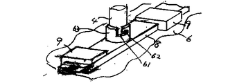
FIG. 1 shows a heating compression volume reducing machine 1. It comprises a compression chamber or heating / compression chamber central axis 4, a weight pressurizing plate or pressurizing and heating plate 5, and an insertion take-out
A
FIG. 2 is a cross-sectional view corresponding to FIG. In both figures, the
The
FIG. 3 shows that at the start of the operation, the compression spring is pushed by hand to push the
The drawer of the
FIG. 5 is a plan view of a shaft arrangement or a corresponding pressing surface when there are two shafts 4. FIG. 6 shows an example of the arrangement of fixing hooks on the pressing surface such as a pressing surface and a lifting wire rope, a chain, a wire, or the like. FIG. 7 is a schematic diagram of a pressurized surface structure in which one side slides in parallel with the surface to open and close, and a waste is put into the
FIG. 11 shows a container for taking out a vertical lattice. The bottom is also a lattice and has a hole 59 through which the central axis of the pressurizing device passes. In FIG. 12, the upper part is a coil-shaped container wall, the lower part is an annular lattice, and the center pillar is hangable for mounting. The lattice part expands and contracts and can be used as an independent waste and waste container, and can be directly charged into a compression chamber or a heating compression chamber. When the central axis is attached, the central axis is composed of multiple telescopic cylinders with a built-in spring. FIG. 13 shows a shape in which a vertical lattice is woven in the coiled container wall. In FIG. 14, the
FIG. 19 shows the fixing structure of the bottom of the device and the container. The central shaft 4 can remove the connecting member 63 in the clockwise rotation and remove the
FIG. 20 shows a volume reducing device for winding and compressing waste plastic in a plastic bag around a shaft. The plastic bag 67 containing the
[0014]
[Action]
Put the waste container with waste in the heating and pressurizing chamber or put the waste in the container for removal in the heating and pressurizing chamber, and prevent the movable heating and pressing surface from swaying along one or more axes. It moves and compresses to maintain the shape consistency of the waste, and to reduce the volume of waste plastic, waste paper, garbage, metal sheet, glass and ceramics while preventing damage to the equipment.
[0015]
EXAMPLE 1 In FIG. 1, a fixed-type radiant heater, a heating surface heater and a thermocouple are built in, and a waste disposal apparatus 1 for recycling with a temperature controller is attached. It was pressed into a
Example 2 Similarly to Example 1, the waste packaging material (bulk specific gravity 0.18) of the vinyl chloride shrink film was heated at a maximum heating system temperature of 140 ° C. or less and heated under a 6 kg weight for 120 minutes. . An odorless reusable block having a thickness of 50 mm, a perforated disk and easily was obtained without melting.
[0016]
Example 3 Roll-up and compression were performed under the same temperature conditions and then compressed in the axial direction of the rotating shaft. A waste packaging film or sheet product was put into a high-density polyethylene bag, and was treated at a diameter of 10 cm, about 4 liters and 50 g, and a bulk specific gravity of 0.013. The volume reduction ratio was 1/10.
Example 4 A long-diameter agricultural polyethylene film used in a greenhouse was blown with hot air of 100 to 150 ° C. or less under the condition that it did not melt, and the inside diameter and height of the mold shown in FIG. 4 were 450 mm and the shaft diameter was 60 mm. After being wound up while rotating the shaft and packed in the
Example 5 A vinyl chloride film was treated in the same manner as in Example 3. The maximum temperature of the heating system was 140 ° C. or less and required 60 minutes. The bulk specific gravity became 0.6.
Example 6 An expanded polystyrene dish was treated as in Example 1. The heating surface temperature was 140 ° C. In 60 minutes, the bulk specific gravity could be reduced to 0.6 and 1/10.
Example 7 A natto container made of expanded polystyrene was treated in the same manner as in Example 1. The bulk specific gravity was 0.011, and the accumulated specific gravity became 0.005 to 0.5. In the 30-minute treatment, the volume became 0.2, and the volume reduction rates were 1/100 and 1/40, respectively.
Example 8 As in Example 1, rolled paper dust (bulk specific gravity: 0.08) of an office note was heated and compressed. The bulk specific gravity was 0.13 by applying a pressure of 0.005 kg / cm2, which was reduced to 1 / 1.5.
Example 9 Garbage was dehydrated under pressure by a compression heating and drying apparatus having an inner diameter of 12 cm and a height of 30 cm shown in FIG. A 50 kg weight or a spring load was applied. The initial volume of 1.3 liters could be dehydrated and reduced to 0.4 liters in 10 minutes. Water could be drained from the pressurized surface gap and the bottom drain hole. Next, the upper and lower heaters were heated with a 200-watt heater in total, 400 watts, and dried to 15% moisture in 3 hours. The volume was reduced to 1/3. A conventional water condensation and deodorization system was used. The exhaust gas had a small amount of thermal expansion and no exhaust odor in the vicinity.
(Comparative Example) It took 9 hours to heat and dry without applying pressure or preliminary dehydration.
[0017]
Example 10 The foamed PS dish bulk specific gravity 0.015 was heated and compressed at 150 ° C. for 1 hour by the apparatus shown in FIG. 1 to reduce the bulk specific gravity to 0.4 and 1/25. The volume of PS-based lactic acid beverage bottles could also be reduced to 1/20 or less. Odorless by using activated carbon adsorbent. Thermosetting materials such as PET bottles, fibers, natural or synthetic rubbers, glass fiber reinforced plastics, unsaturated polyesters and the like having a softening temperature of around 170 ° C. or less could similarly be heated and pressed at 170 ° C. to reduce the volume.
[0018]
Example 11 PP packing string and polyethylene film waste were heated and compressed at 140 ° C. to reduce the volume. A fluorinated film was placed between the heated surface and the waste. There was no stickiness between the heated surface and the waste. When the fluorine-based film was not used, there was partial adhesion.
[0019]
【effect】
Especially suitable for use with small household appliances and commercial equipment that can be heated and compressed at low temperatures and low pressures, sterilized, and deodorized. It is also effective for medical and nursing care waste treatment, economical recycling of waste, low cost of garbage collection and transportation, labor shortage countermeasures, vehicle fuel saving, and global warming countermeasures. It should be noted that conversion, mutual combination, and omission may be performed as long as the features of the present invention described above are retained, and the effect can be increased by a combination with a known technique.
[Brief description of the drawings]
FIG. 1 is a vertical cross-sectional front view of a heating / compression volume reducing machine having a heating surface lifting function also serving as a weight. FIG. 2 is a vertical cross-sectional side view of the heating / compression volume reducing machine. FIG. FIG. 4 is a vertical sectional side view of a heating structure using a shaft of a heating compression volume reducing machine. FIG. 5 is a plan view of an arrangement of two heating surfaces or a pressing surface. FIG. 6 is a plan view of an arrangement of lifting hooks on the heating surface. FIG. 7 is a plan view in which one side of the pressing surface is opened and closed. FIG. 8 is a plan view in which a notch is formed to open and close the pressing surface. FIG. 9 is a plan view of a square heating / compression chamber and a pressing plate. Pressing plate plan view [Figure 11] Vertical grid, bottom also takes out grid, container plan view [Figure 12] Upper coiled wall, lower annular grid container same front view [Figure 13] Coiled container wall plan view, in which vertical grid is woven Fig. 14 Side view where the side wall coil and the vertical lattice are fastened with an annular bracket [Figure 15] Side view of side wall coil and vertical lattice fixed by coil [Figure 16] Side view of side wall coil and vertical lattice fixed to sheet metal [Figure 17] Side view of side wall coil and vertical lattice fixed by wire Outline drawing [FIG. 18] Side elevation drawing in which side wall coils are fastened with oblique steel wires [FIG. 19] Outline drawing of the fixing structure of the bottom of the apparatus and the container [FIG. 20] Lateral explanatory view of the winding type heat compression volume reduction machine [FIG. ] Side view explanatory diagram of a winding type heat compression volume reduction machine using a Messibelt [Description of symbols]
1 heating compression volume reduction machine, 2 compression chamber or heating compression chamber, 4 central shaft or guide,
5 pressurized or pressurized heating plates, 7 extraction containers,
19, 69 handle, 28 girder frame, 23 perforated plate or net, 24 gap,
27 Heat compression surface, 34 Waste plastic, waste such as paper,
64 take-up roll, 74 pull-in facing roll,
66 and 68 Compressed surface, Heated compressed surface, 67 Plastic bag, Folded film,
76 Hold down, 77 Bottom of plastic bag.
Claims (10)
Priority Applications (1)
| Application Number | Priority Date | Filing Date | Title |
|---|---|---|---|
| JP2002208910A JP2004017150A (en) | 2002-06-14 | 2002-06-14 | Method and apparatus for reducing volume of wastes |
Applications Claiming Priority (1)
| Application Number | Priority Date | Filing Date | Title |
|---|---|---|---|
| JP2002208910A JP2004017150A (en) | 2002-06-14 | 2002-06-14 | Method and apparatus for reducing volume of wastes |
Publications (1)
| Publication Number | Publication Date |
|---|---|
| JP2004017150A true JP2004017150A (en) | 2004-01-22 |
Family
ID=31184316
Family Applications (1)
| Application Number | Title | Priority Date | Filing Date |
|---|---|---|---|
| JP2002208910A Pending JP2004017150A (en) | 2002-06-14 | 2002-06-14 | Method and apparatus for reducing volume of wastes |
Country Status (1)
| Country | Link |
|---|---|
| JP (1) | JP2004017150A (en) |
Cited By (4)
| Publication number | Priority date | Publication date | Assignee | Title |
|---|---|---|---|---|
| CN105235252A (en) * | 2015-10-29 | 2016-01-13 | 黄霞 | Environment-friendly equipment for recycling kitchen waste |
| CN106238454A (en) * | 2016-09-21 | 2016-12-21 | 上海环境工程技术有限公司 | A kind of method removing heavy metal in soil for renovation agent with changing food waste organic acid fermentation liquid |
| KR101731207B1 (en) * | 2016-02-15 | 2017-04-27 | 건양대학교산학협력단 | An apparatus supplying and returning operating gowms |
| CN109127703A (en) * | 2018-10-30 | 2019-01-04 | 中国矿业大学 | A kind of contaminated soil in-situ remediation system and method |
-
2002
- 2002-06-14 JP JP2002208910A patent/JP2004017150A/en active Pending
Cited By (4)
| Publication number | Priority date | Publication date | Assignee | Title |
|---|---|---|---|---|
| CN105235252A (en) * | 2015-10-29 | 2016-01-13 | 黄霞 | Environment-friendly equipment for recycling kitchen waste |
| KR101731207B1 (en) * | 2016-02-15 | 2017-04-27 | 건양대학교산학협력단 | An apparatus supplying and returning operating gowms |
| CN106238454A (en) * | 2016-09-21 | 2016-12-21 | 上海环境工程技术有限公司 | A kind of method removing heavy metal in soil for renovation agent with changing food waste organic acid fermentation liquid |
| CN109127703A (en) * | 2018-10-30 | 2019-01-04 | 中国矿业大学 | A kind of contaminated soil in-situ remediation system and method |
Similar Documents
| Publication | Publication Date | Title |
|---|---|---|
| JP4085366B2 (en) | Waste recycling method and equipment | |
| JP2004050160A6 (en) | Waste recycling method and equipment | |
| EP0524608B1 (en) | Refuse compression apparatus | |
| JP2003053299A (en) | Method and apparatus for thermal compression treatment of waste | |
| JP2004017150A (en) | Method and apparatus for reducing volume of wastes | |
| WO2017109806A1 (en) | Device for prolonging the storage of organic waste | |
| JP7437052B2 (en) | Collection method for used sanitary products and collection tools used in this collection method | |
| GB2278311A (en) | Compactor | |
| JP3364803B2 (en) | Paper and waste plastic processing | |
| JP2004105936A (en) | Cooking range and waste disposal method | |
| FI103274B (en) | Procedure for collection of biowaste from households | |
| JP3089736B2 (en) | Plastic waste treatment equipment | |
| JP3177368B2 (en) | Plastic waste treatment equipment | |
| JP2002282828A (en) | Garbage heat processing method and equipment | |
| JP2003250878A (en) | Apparatus and method for disposing of diaper | |
| JP2006130132A (en) | Treatment apparatus of used nursing care goods | |
| JP2020108876A (en) | Waste plastic small-sized volume reduction apparatus and processing method | |
| JP2020131695A (en) | Waste plastic volume-reduction small device and processing method | |
| JP2563680B2 (en) | Garbage disposal | |
| JP2002059134A (en) | Method of treating organic waste | |
| JPH08168739A (en) | Method for reducing volume of waste and device for reducing volume of waste | |
| JPH07124949A (en) | Disposal device and method of plastic waste | |
| JPH11138538A (en) | Volume reducing machine of pet bottle | |
| JPH04317909A (en) | Refuge disposal apparatus | |
| JP2001047008A (en) | Method and apparatus for heating or pressuring treatment of waste |
Legal Events
| Date | Code | Title | Description |
|---|---|---|---|
| A621 | Written request for application examination |
Free format text: JAPANESE INTERMEDIATE CODE: A621 Effective date: 20050609 |
|
| A977 | Report on retrieval |
Free format text: JAPANESE INTERMEDIATE CODE: A971007 Effective date: 20071214 |
|
| A131 | Notification of reasons for refusal |
Free format text: JAPANESE INTERMEDIATE CODE: A131 Effective date: 20071225 |
|
| A02 | Decision of refusal |
Free format text: JAPANESE INTERMEDIATE CODE: A02 Effective date: 20080513 |