JP2004013401A - Communication system for vehicle, vehicle, and communication device for vehicle - Google Patents
Communication system for vehicle, vehicle, and communication device for vehicle Download PDFInfo
- Publication number
- JP2004013401A JP2004013401A JP2002164267A JP2002164267A JP2004013401A JP 2004013401 A JP2004013401 A JP 2004013401A JP 2002164267 A JP2002164267 A JP 2002164267A JP 2002164267 A JP2002164267 A JP 2002164267A JP 2004013401 A JP2004013401 A JP 2004013401A
- Authority
- JP
- Japan
- Prior art keywords
- light
- vehicle
- signal
- light emitting
- emitting device
- Prior art date
- Legal status (The legal status is an assumption and is not a legal conclusion. Google has not performed a legal analysis and makes no representation as to the accuracy of the status listed.)
- Pending
Links
Images


Classifications
-
- G—PHYSICS
- G08—SIGNALLING
- G08G—TRAFFIC CONTROL SYSTEMS
- G08G1/00—Traffic control systems for road vehicles
- G08G1/16—Anti-collision systems
- G08G1/164—Centralised systems, e.g. external to vehicles
-
- B—PERFORMING OPERATIONS; TRANSPORTING
- B60—VEHICLES IN GENERAL
- B60Q—ARRANGEMENT OF SIGNALLING OR LIGHTING DEVICES, THE MOUNTING OR SUPPORTING THEREOF OR CIRCUITS THEREFOR, FOR VEHICLES IN GENERAL
- B60Q1/00—Arrangement of optical signalling or lighting devices, the mounting or supporting thereof or circuits therefor
- B60Q1/26—Arrangement of optical signalling or lighting devices, the mounting or supporting thereof or circuits therefor the devices being primarily intended to indicate the vehicle, or parts thereof, or to give signals, to other traffic
- B60Q1/50—Arrangement of optical signalling or lighting devices, the mounting or supporting thereof or circuits therefor the devices being primarily intended to indicate the vehicle, or parts thereof, or to give signals, to other traffic for indicating other intentions or conditions, e.g. request for waiting or overtaking
- B60Q1/503—Arrangement of optical signalling or lighting devices, the mounting or supporting thereof or circuits therefor the devices being primarily intended to indicate the vehicle, or parts thereof, or to give signals, to other traffic for indicating other intentions or conditions, e.g. request for waiting or overtaking using luminous text or symbol displays in or on the vehicle, e.g. static text
- B60Q1/5035—Arrangement of optical signalling or lighting devices, the mounting or supporting thereof or circuits therefor the devices being primarily intended to indicate the vehicle, or parts thereof, or to give signals, to other traffic for indicating other intentions or conditions, e.g. request for waiting or overtaking using luminous text or symbol displays in or on the vehicle, e.g. static text electronic displays
-
- G—PHYSICS
- G08—SIGNALLING
- G08G—TRAFFIC CONTROL SYSTEMS
- G08G1/00—Traffic control systems for road vehicles
- G08G1/09—Arrangements for giving variable traffic instructions
- G08G1/091—Traffic information broadcasting
- G08G1/092—Coding or decoding of the information
-
- G—PHYSICS
- G08—SIGNALLING
- G08G—TRAFFIC CONTROL SYSTEMS
- G08G1/00—Traffic control systems for road vehicles
- G08G1/09—Arrangements for giving variable traffic instructions
- G08G1/0962—Arrangements for giving variable traffic instructions having an indicator mounted inside the vehicle, e.g. giving voice messages
- G08G1/0967—Systems involving transmission of highway information, e.g. weather, speed limits
- G08G1/096766—Systems involving transmission of highway information, e.g. weather, speed limits where the system is characterised by the origin of the information transmission
- G08G1/096783—Systems involving transmission of highway information, e.g. weather, speed limits where the system is characterised by the origin of the information transmission where the origin of the information is a roadside individual element
-
- G—PHYSICS
- G08—SIGNALLING
- G08G—TRAFFIC CONTROL SYSTEMS
- G08G1/00—Traffic control systems for road vehicles
- G08G1/16—Anti-collision systems
- G08G1/161—Decentralised systems, e.g. inter-vehicle communication
Abstract
Description
【0001】
【発明の属する技術分野】
本発明は車両用通信システム、車両、および車両用通信装置に係り、とくに光を用いて情報の伝達を行なう車両用通信システム、車両、および車両用通信装置に関する。
【0002】
【従来の技術】
例えば特開平9−51309号公報には、車両前方に対してレーザ光信号を受信又は発信する前方投受光部と、車両後方に対してレーザ光信号を受信又は発信する後方投受光部と、前方投受光部により受信した信号を含むレーザ光信号を後方投受光部から発信するとともに、後方投受光部により受信した信号を含むレーザ光信号を前方投受光部から発信するように、前方投受光部と後方投受光部の間の信号の中継を行なう信号中継手段とを設けることにより、車両間の信号の順送りを可能にし、例えば道路が渋滞し走行方向に多数の車両が列をなすような場合でも、また高速道路等において車間距離が非常に長い場合や、車車間の大気の透過性が雨や霧等により悪化している場合でも、特定の車両の有する情報が確実に他の車両に伝えられるようにした車車間通信システムが提案されている。
【0003】
また特開2001−158390号公報には、乗員が鞍乗する鞍乗型車両において、車両間で情報交換可能な送受信機を備えた通信装置を、ライト手段に隣接して配置することによって、通信装置の配置スペースを容易に確保でき、しかも通信装置の位置の調整が容易で、受信性能が向上する車両間通信装置が開示されている。
【0004】
【発明が解決しようとする課題】
特開平9−51309号公報によって提案されている車車間通信システムは、レーザ光信号を用いて車車間での情報の伝達を行なうために、専用のレーザ光を発光する投受光部を車両の前後に備えなければならず、これによってコストが増大する。しかもこのような装置は、レーザ光によって情報の伝達を行なうために、上記投受光部から発光されたレーザ光が人体に当ると、当該部分が損傷される可能性があり、安全性に問題を生ずる。
【0005】
また特開2001−158390号公報に開示されている車車間通信装置は、ライト手段に隣接して別の送受信機を備えるために、複数の光源手段が新たに必要になって装置が複雑になる。またこれによってコストが増大する欠点がある。
【0006】
本発明はこのような問題点に鑑みてなされたものであって、新たな専用の発光手段を設けることなく、しかも光によって車両用通信を可能にする車両用通信システム、車両、および車両用通信装置を提供することを目的とする。
【0007】
【課題を解決するための手段】
本願の主要な発明は、固定配置された発光装置と、
該発光装置が発光する光に所定の信号を重畳する変調器と、
車両側に設けられ、前記発光装置によって発光されかつ信号が重畳された光を受光する受光装置と、
前記受光装置によって受光された光に重畳された信号を読出すデコーダと、
前記デコーダによって読出された信号に基く情報を報知する報知手段と、
を具備する車両用通信システムに関するものである。
【0008】
ここで前記発光装置が信号機の信号灯、街路灯、踏切りの警報灯、路面に埋込まれた埋込み式の信号灯、軌道に設置された信号機の信号灯であってよい。とくに軌道に設置された信号機の信号灯である場合には、この信号灯が鉄道車両の受光装置によって受光されることになる。また前記変調器が前記発光装置の駆動電流にコードパルスを重畳して変調するものであってよい。
【0009】
本願の別の主要な発明は、外に向って光を発する発光装置と、
前記発光装置が発光する光に所定の信号を重畳する変調器と、
他の車両の前記発光装置によって発光されかつ信号が重畳された光を受光する受光装置と、
前記受光装置によって受光された光に重畳された信号を読出すデコーダと、
前記デコーダによって読出された信号を出力する出力手段と、
を具備する車両に関するものである。
【0010】
ここで前記発光装置がヘッドランプ、テールランプ、ブレーキランプ、方向指示灯等のような車両に設けられておりかつ外部に向って照明光または警報光を発するランプであってよい。また前記複数の車両間の情報の伝達を行なうものであってよい。
【0011】
またここで前記デコーダが受信した信号を識別する識別手段を具備し、識別符号が一致した信号のみを読出して出力するようにしてもよい。また前記デコーダが受信した信号の種類を判別する判別手段を具備し、種類に応じて信号処理することが好適である。また前記判別手段が信号に付加されたカテゴリ信号によって種類を判別することが好ましい。またキー操作手段を備え、該キー操作手段の単一の操作に応じて前記車両に設けられた複数の発光装置からの光に異なる信号を重畳してそれぞれの発光装置から光を発することが好適である。
【0012】
本願のさらに別の主要な発明は、固定配置された発光装置と、
該発光装置が発光する光に所定の信号を重畳する変調器とを備え、
該変調器によって変調された光を外部車両に発光することにより通信を行なう車両用通信装置に関するものである。
【0013】
ここで前記発光装置がLEDから成ることが好ましい。また前記発光装置が信号機の信号灯あるいは踏切りの警報灯であることが好適である。
【0014】
本願のさらに別の主要な発明は、所定の信号が重畳された光を受光する受光装置と、
前記受光装置によって受光した光に重畳された信号を読出すデコーダと、
前記デコーダによって読出された信号に基く情報を報知する報知手段と、
を具備する車両用通信装置に関するものである。なおここで前記報知手段が表示装置であことが好適である。
【0015】
本願に含まれる発明の好ましい態様は、固車間または車車間の送受信を可能な装置と、ユーザインターフェースとなる表示部と、操作部とを有し、固定側あるいは車両の発光機器を用いて信号を授受する送受信システムに関する。このようなシステムによれば、比較的近傍に位置する固定装置と車両との間あるいは車両と車両との間の情報の伝達による通話が可能となる。また固定装置あるいは車両が発生する光に変調をかけて信号を重畳させることにより信号を授受するために、固定装置あるいは車両の発光装置の本来の機能がそのまま保持され、新たな発光装置を必要としない。
【0016】
【発明の実施の形態】
(1)実施の形態1(固定装置と車両との間の通信装置、図1〜図8)
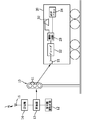
第1の実施の形態の典型的な例を図1〜図4によって説明する。この装置は固定配置された信号機と車両との間で情報の伝達を行なう車両用通信装置に関する。図1に示すように道路の交差点等に配置された信号機10は青色、黄色、赤色の3つの信号灯11を備えている。信号灯11の発光部は例えばLED(Light Emitting Diode)によって構成される。これらの信号灯11は従来公知の信号機駆動回路12によって駆動される。そしてこの駆動回路12と信号灯11との間に変調器13が接続される。変調器13はさらに受信機14と接続され、この受信機14がアンテナ15を介して外部から指令信号を受信する。
【0017】
これに対して自動車20側には受光器21と、デコーダ22と、駆動回路23と、表示パネル24が設けられる。
【0018】
図2は上記通信装置のより具体的な構成を示しており、その左側の部分が信号機10側の装置を示している。ここでシステムはCPU16を備え、このCPU16が受信機14と信号機駆動回路12と変調器13との間に介在され、これらを制御するようになっている。
【0019】
また図2において右側のシステムが車両20側のシステムであって、ここではCPU25がデコーダ22に接続されている。そしてCPU25には操作入力部26とメモリ27と、ドライバ23とが接続されている。ドライバ23が表示パネル24を駆動する。
【0020】
以上のような構成において、信号機10側の受信機14はアンテナ15を通して指令装置から無線で指令信号を受信する。そしてこの指令信号を変調器13に伝達する。変調器13は信号機駆動回路12によって発生される信号灯11の駆動電流に上記指令信号を重畳する。従って信号灯11は表示点灯のための光に指令信号を重畳した状態で発光する。
【0021】
上記の指令信号を重畳した光が車両20の受光器21によって受光され、デコーダ22によって信号の復調が行なわれる。従ってこのような信号を駆動回路23に供給し、表示パネル24によって表示させる。
【0022】
ここで信号灯11の光に重畳される情報としては、交通規制に関する情報や、右折禁止の情報、あるいは一方通行に関する情報であってよい。あるいはまた信号が後どの位の時間経過すると青になって通行できるか等の時間を表示するものであってよい。またこの情報は一定時間毎に、あるいは必要に応じて発せられる。
【0023】
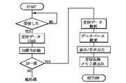
図3はこのような車両用通信装置の動作の1例を示しており、ここでは車両20側のデコーダ22に接続されたCPU25が信号を受信したかどうかの判別を行なうとともに、受信した場合にはその受信データをCPU25のD−RAM上にロードする。そして受信データとのIDの照合比較を行なうとともに、IDが一致した場合にのみ受信データを解析し、メモリ27に蓄えられているデータベースの検索を行なう。そしてデータベースによって与えられる表示内容を表示パネル24によってドライバ23が表示動作する。なおここでIDの照合を行なうのは、不要な情報の表示を省略し、あるいはまた不要な情報をカットするためである。なおこのIDの照合の動作は必要に応じて省略できる。
【0024】
ここで信号灯11の駆動電流に変調器13によって信号を変調する変調方式には、各種の変調方式が可能であって、AM変調、FM変調、パルス幅変調、パルスコード変調等の各種の変調方式が適宜採用される。
【0025】
図4はパルスコード変調方式による信号の構成例を示しており、ここでは1つのフレームを45msの時間のサイクルフレームとして構成した例を示している。ここでそれぞれのフレームはガイドパルスとデータコードとカテゴリコードとから構成される。これらのパルスの具体的な構成例は表1に示される。
【0026】
【表1】

上記の表1から明らかなように、ガイドパルスは2.4msのパルス幅を有し、これに対してデータコードは“0”を示す0.6msのパルス幅のパルスと“1”を示す1.2msのパルスとを順次形成して所定の情報の伝達を行なう。なおこのような変調器13によるパルスの形成はあくまでも一例であって、目的や情報の長さに応じて各種の形態のものが採用可能である。
【0028】
また上記のようなパルスコード方式で信号灯11の発生する光に信号を重畳する場合には、応答性に優れたLEDによって信号灯11を構成することが好ましい。なお信号機10の形態については各種のものに応用でき、また車両用信号機10のみならず、横断歩道に設置される歩行者用信号に適用してもよい。
【0029】
次に上記実施の形態の変形例を図5によって説明する。この実施の形態は道路に配置された街路灯30と車両20との間での通信を行なうための装置である。ここでも街路灯30には照明灯駆動回路12に変調器13が接続され、しかもこの変調器13が受信機14に接続されている。そして受信機14はアンテナ15を備え、指令基地から信号を受信する。なおここで街路灯30としてはLED、キセノンランプ、放電管、HID等のような光源を用いることが好適であって、変調器13による変調に対して応答性が確保できる。これに対して車両20側には受光器21と、デコーダ22と、駆動回路23と、表示パネル24とが設けられる。
【0030】
従って変調器13によって信号が重畳された光を街路灯30が発することになり、この光を車両20の受光器21によって受光し、デコーダ22によって読出して駆動回路23を通して表示パネル24に表示する。従って表示パネル24によって所定の表示が行なわれる。なおここで行なわれる表示としては、この街路灯が設置された位置の表示や、道路の一方通行等の交通規制の内容、あるいはまた道路の渋滞状況等の情報であってよい。また信号が重畳された光を発する街路灯としては、図5に示すものの他各種の形態の街路灯に広く適用可能である。
【0031】
図6はさらに別の実施の形態を示している。ここでは踏切りに設けられている警報灯31と車両20との間で情報の伝達を行なうための通信装置に関するものである。すなわちここでは踏切りの警報灯31には警報灯駆動回路12と変調器13とが接続される。これに対して車両側には受光器21と、デコーダ22と、駆動回路23と、表示パネル24とが設けられる。警報灯31の発光部は例えばLEDで構成される。
【0032】
従って変調器13によって信号が重畳された光を警報灯31が発するようになり、この光を車両20側の受光器21によって受光し、デコーダ22によって復調して駆動回路23で表示パネル24に表示を行なわせる。従って警報灯31に重畳された信号が表示パネル24に表示されるようになる。
【0033】
このような踏切りの警報灯31による表示の内容は、例えばこの踏切りが開くまでの時間や、事故に関する情報等であってよい。
【0034】
また図6に示す踏切りの警報灯31の代りに、図7に示すように踏切りの遮断バー33に警報灯31を取付け、この警報灯31によって信号が重畳された光を発生することも可能である。この場合にも、警報灯31が発する光が車両20の受光器21によって受光されると、デコーダ22によって信号の内容が読出され、駆動回路23によって表示パネル24に表示が行なわれる。
【0035】
図8に示す変形例は、道路の交差点等の部分に埋込まれた信号灯11であってよく、この信号灯11を駆動する駆動回路12と信号灯11との間に変調器13を接続している。これに対して車両20側には受光器21と、デコーダ22と、駆動回路23と、表示パネル24とが接続される。信号灯11の発光部は例えばLEDで構成される。
【0036】
従って車両20が交差点に差しかかると、車両の先端部に設けられた受光器21が信号を重畳した光を信号灯11から受光器21によって受光する。そしてこの受光した光中の信号の内容をデコーダ22によって読出し、駆動回路23で表示パネル24によって表示できるようになる。ここでは車両が通過する方向が優先なのかどうか、あるいはまた右折あるいは左折の規制の有無等に関する情報を伝達することができる。
【0037】
次に別の実施の形態を図9によって説明する。この実施の形態は鉄道の軌道上の信号機10と鉄道車両20との間での通信に適用したものである。すなわち軌道上に設けられた信号機10の信号灯11と信号機駆動回路12との間に変調器13が接続され、しかもこの変調器13は受信機14と接続される。受信機14はアンテナ15を備え、指令基地からの指令信号を受ける。これに対して車両20側には受光器21と、デコーダ22と、駆動回路23と、表示パネル24と、さらにスピーカ32とが設けられる。信号灯11の発光部は例えばLEDによって構成される。
【0038】
従ってこの車両20が軌道上を走行し、信号機10の近傍に達すると、信号機10の信号灯11からの光を受光部21が受けるようになり、この光に重畳された信号をデコーダ22によって読出し、駆動回路23によって表示パネル24あるいはスピーカ32を駆動し、表示動作あるいは音声の出力動作を行なう。なおここで行なわれる表示の内容としては、車両20に対する運行の指示動作であってよい。なおその他の事故情報をも併せて伝達することができる。
【0039】
(2)実施の形態2(車両と車両との間の通信装置、図10〜図16)
この実施の形態は、車両間での光による情報の伝達を行なうための通信装置である。すなわち図10に示すように車両に予め設けられているヘッドランプ35あるいはテールランプ36が用いられる。そしてこれらのランプ35、36に対して信号を重畳するための変調器13が接続される。また車両20には光を受信するための受光器21がこの前部と後部とに設けられる。そしてこれらの受光器21はデコーダ22に接続される。なおこれらのランプ35、36にはLED、キセノンランプ等の光源が用いられ、変調器13による変調に対する応答性が確保される。
【0040】
図11はこのような車両用の通信装置のシステム構成を示しており、受光器21にデコーダ22が接続され、このデコーダ22はさらにCPU25に接続される。そしてCPU25が変調器側のCPU16に接続されるようになっている。変調器13は駆動回路23とヘッドランプ35との間に接続される。そして上記CPU16にキー操作部26と表示パネル24とメモリ27とが接続されている。
【0041】
このように車両間の通信に用いられるシステムは、受光部21によって外部からの信号を受けるようになっている。ここでは可視光領域の光を受けるフォトトランジスタによって受光部21が構成される。そしてデコーダ22によって受信した内容がCPU25を通してCPU16に送られ、データまたはプログラムの処理を行なった後に、メモリ27に蓄えられる。なおメモリ27にデータベースを有し、送信側の情報を検索し、送信者氏名や企業名等の詳細を表示パネル24によって表示するようにしてもよい。また音声データ蓄積によって送信内容を音声で再生することも可能である。
【0042】
図12は図11に示すシステムの受信動作を示しており、CPU25がデコーダ22が受信したかどうかの検出を行なう。そして受信した場合にはそのデータをCPU25のD−RAMにロードし、ID照合の比較を行なう。ID照合の比較を行なう理由は、不要な通信データを受信した場合に、IDの照合によって表示すべきもののみを抽出するためである。そしてIDが一致した場合には受信データを解析し、メモリ27上のデータベースを検索し、この後表示あるいは音声出力を行なう。さらに必要に応じて受信記録を行ない、メモリ27に書込むようにする。
【0043】
このように本実施の形態の通信装置は、受信データに含まれるIDデータによって受取り側が許可を確認する。許可が確認された場合にはデータを解析し、データが音声コードであった場合にはコードに適応する音声データを、例えばCD−ROM等のデータベースから検索して発声する。音声データ自体が受信された場合に、音声データを発声することも可能である。表示データの場合には、文字データであればそのまま表示する。ここで表示としては「ありがとう」、「お先にどうぞ」、「右折して下さい」、「止まります」等が挙げられる。自車に既存のデータベースから発信者のデータを同時に表示することも可能である。
【0044】
図13は車両20側でヘッドランプ35やテールランプ36を用いて情報を発信する動作を示す。ここではCPU16が発信指令があったかどうかの判断を行なう。なお発信指令の判断は、キー操作部26に運転者が入力操作を行なったかどうかによって行なう。そして発信指令があった場合にはCPU16のD−RAMに入力データのローディングを行ない、しかもCPU16はIDデータとカテゴリデータの付加を行なう。そしてこの後に発信すべきデータを変調器13に送信する。変調器13はこの信号を駆動回路23からの駆動電流に重畳して変調する。従って信号が重畳された電流によってヘッドランプ35が発光動作を行なうことになる。なおこのときに発信記録をCPU16に接続されたメモリ27によって蓄えておくことができる。
【0045】
なお車両20間の通信において、複数の車両から同時に信号が送られた場合には、これらを互いに識別する必要がある。そこで図14に示すように、このような場合の誤動作を防止するために、デコーダ22の前段であって受光器21の後段に互いに並列に互いに別々の周波数にロックされた複数のPLL37、38、39、40を接続することができる。PLLは位相比較器とLPF(ローパスフィルタ)とVCO(Voltage controlled oscillator)とから構成され、同期検波を行なうために、これによって複数の信号を識別して所定の信号のみを抽出し、これをデコーダ22に取出することが可能になる。従って複数の車両20から同時に信号を受取った場合の受信側の誤動作が防止される。
【0046】
図15は変形例を示している。ここでは単一の操作に基いて複数の車両に対して互いに別々の信号を送出する例である。例えば、交差点に自車(図15の車両20)が近づいたときに対向車で右折を待っている車両(図15の左側の車両50)があり、自車20が一旦停止してその対向車50に右折を許容する場合がある。このような場合に後続車両(図15の右側の車両51)には予め停止する意思を表示しておけば、後続車両51による追突や急ブレーキ操作を回避できる。
【0047】
従って対向車50に右折を許容する意思表示を行なう場合に、1つのキー操作に応じて、真中に位置する車両20はその変調器13によって前方の車両50に対して右折を許容する「右折どうぞ」の内容の信号をヘッドランプ35の光に重畳して送信する。同時に後方の車両51に対しては、テールランプ36によって変調器13が、停止の意思表示に当る「止まります」の信号を送信する。
【0048】
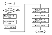
図16はこのような動作を示しており、例えば1つのキー操作に応答して図11に示すCPU16が発信指令を受取った場合に、前方の車両に対する第1の入力データをロードし、次いで後方の車両に送信する第2のデータをロードする。そしてこれらのデータに対してIDデータを付加し、第1入力データを変調器13によって変調してヘッドランプ35の駆動電流に重畳する。これによってヘッドランプ35が変調光を発光する。次いでCPU16は第2入力データを変調器13に供給し、テールランプ36を駆動する駆動電流に上記の第2データの信号を重畳する。従ってテールランプ36は後方の車両に対する伝達情報を重畳した変調光を発生する。これによって前方の車両50と後方の車両51とに互いに別々のデータをほぼ同時に供給することが可能になる。
【0049】
以上本願に含まれる発明を図示の実施の形態によって説明したが、本願の発明は上記実施の形態によって限定されることなく、本願に含まれる発明の技術的思想の範囲内で各種の変更が可能である。例えば本発明は、例示した以外の固定式の発光装置と車両との間での通信に利用することができる。あるいはまた本発明は、例示した発光装置以外の発光装置を用いて車両と車両との間での情報の伝達を行なうようにしてもよい。また情報を表示する表示パネルの代りにスピーカを用いて音声によって報知してもよい。
【0050】
また本願に含まれる発明は信号灯、警告灯、車両のヘッドランプ等の発光装置の発光に変調光を重畳し該重畳された変調光を受光するため、外界の光の影響を受けることが考えられる。従って、発光装置の出力光の波長を抽出し得る偏光フィルタ、バンドパスフィルタ回路等を用いると効果的である。あるいは、例えば太陽光を遮るための遮光板や、受光部を車体から引っ込んだ位置に設置する等の変形も考えられる。
【0051】
【発明の効果】
本願の主要な発明は、固定配置された発光装置と、該発光装置が発光する光に所定の信号を重畳する変調器と、車両側に設けられ、発光装置によって発光されかつ信号が重畳された光を受光する受光装置と、受光装置によって受光された光に重畳された信号を読出すデコーダと、デコーダによって読出された信号を出力する出力手段と、を具備するものである。
【0052】
従ってこのような車両用通信装置によれば、固定配置された発光装置の機能を損うことなくそのまま利用して車両との間での通信による情報の伝達を確立することが可能になる。
【0053】
本願の別の主要な発明は、車両に設けられ、外に向って光を発する発光装置と、発光装置が発光する光に所定の信号を重畳する変調器と、車両に設けられ、他の車両の発光装置によって発光されかつ信号が重畳された光を受光する受光装置と、受光装置によって受光された光に重畳された信号を読出すデコーダと、デコーダによって読出された信号を出力する出力手段と、を具備するものである。
【0054】
従ってこのような車両によれば、車両に設けられ、外に向って光を発する発光装置の機能を損うことなくそのまま用いて車両と車両との間での通信を行なうことが可能になる。従って新たな発光装置を必要とせず、構成が簡潔になるばかりでなく、コスト的にも有利な通信装置を備える車両が提供される。
【0055】
本願のさらに別の主要な発明は、固定配置された発光装置と、該発光装置が発光する光に所定の信号を重畳する変調器とを備え、該変調器によって変調された光を外部車両に発光することにより通信を行なうようにしたものである。
【0056】
従ってこのような車両用通信装置によれば、固定配置された発光装置を用いて固定装置から車両に対して信号を送信して情報の伝達を行なうことが可能になる。
【0057】
本願のさらに別の主要な発明は、所定の信号が重畳された光を受光する受光装置と、受光装置によって受光した光に重畳された信号を読出すデコーダと、デコーダによって読出された信号に基く情報を報知する報知手段と、を具備するようにしたものである。
【0058】
従ってこのような車両用通信装置によれば、受光装置によって受光された信号に重畳されている信号をデコーダによって読出すとともに、その信号を報知手段によって報知することによって信号に基く情報を車両側に伝達することが可能になる。
【図面の簡単な説明】
【図1】第1の実施の形態の車両用通信装置のシステム構成を示す正面図である。
【図2】通信装置のシステム構成を示すブロック図である。
【図3】通信装置の動作を示すフローチャートである。
【図4】送信される情報パルスの構成を示す波形図である。
【図5】変形例のシステムの正面図である。
【図6】別の変形例のシステムの正面図である。
【図7】さらに別の変形例のシステム構成を示す正面図である。
【図8】さらに別の変形例のシステムの構成を示す正面図である。
【図9】さらに別の変形例のシステムを示す正面図である。
【図10】第2の実施の形態の車両間の通信装置を示す正面図である。
【図11】車両に設けられている通信装置のシステム構成を示すブロック図である。
【図12】受信動作を示すフローチャートである。
【図13】発信動作を示すフローチャートである。
【図14】検波機能を備える受信部のブロック図である。
【図15】変形例に係る通信装置を示す正面図である。
【図16】同変形例の動作を示すフローチャートである。
【符号の説明】
10‥‥信号機、11‥‥信号灯、12‥‥信号機駆動回路、13‥‥変調器、14‥‥受信機、15‥‥アンテナ、16‥‥CPU、20‥‥車両(自動車)、21‥‥受光器、22‥‥デコーダ、23‥‥駆動回路、24‥‥表示パネル、25‥‥CPU、26‥‥操作入力部、27‥‥メモリ、28‥‥CPU、30‥‥街路灯、31‥‥警報灯、32‥‥スピーカ、33‥‥遮断バー、35‥‥ヘッドランプ、36‥‥テールランプ、37〜40‥‥PLL、50、51‥‥車両[0001]
TECHNICAL FIELD OF THE INVENTION
The present invention relates to a vehicle communication system, a vehicle, and a vehicle communication device, and particularly to a vehicle communication system, a vehicle, and a vehicle communication device that transmit information using light.
[0002]
[Prior art]
For example, Japanese Patent Application Laid-Open No. Hei 9-51309 discloses a front light emitting / receiving unit for receiving or transmitting a laser light signal to the front of a vehicle, a rear light emitting / receiving unit for receiving or transmitting a laser light signal to the rear of the vehicle, The front light emitting and receiving unit transmits the laser light signal including the signal received by the light emitting and receiving unit from the rear light emitting and receiving unit and transmits the laser light signal including the signal received by the rear light emitting and receiving unit from the front light emitting and receiving unit. And signal relay means for relaying signals between the rear light-receiving and light-receiving units, thereby enabling forward transmission of signals between vehicles, for example, when a road is congested and a large number of vehicles line up in the traveling direction. However, even when the inter-vehicle distance is extremely long on a highway, etc., or when the permeability of the air between vehicles is deteriorating due to rain, fog, etc., the information possessed by a specific vehicle can be transmitted to other vehicles without fail. Be Unishi was vehicle-to-vehicle communication systems have been proposed.
[0003]
Japanese Patent Application Laid-Open No. 2001-158390 discloses a straddle-type vehicle in which an occupant straddles a communication device provided with a transceiver capable of exchanging information between the vehicles adjacent to the light means. There is disclosed an inter-vehicle communication device that can easily secure an arrangement space for the device, easily adjust the position of the communication device, and improve reception performance.
[0004]
[Problems to be solved by the invention]
The inter-vehicle communication system proposed in Japanese Patent Application Laid-Open No. 9-51309 discloses an inter-vehicle communication system that transmits and receives information between vehicles by using a laser light signal. To increase the cost. In addition, since such a device transmits information using laser light, if the laser light emitted from the light emitting and receiving unit hits a human body, the relevant part may be damaged, and there is a problem in safety. Occurs.
[0005]
Further, the inter-vehicle communication device disclosed in Japanese Patent Application Laid-Open No. 2001-158390 includes another transceiver adjacent to the light means, so that a plurality of light source means are newly required and the apparatus becomes complicated. . This also has the disadvantage of increasing costs.
[0006]
SUMMARY OF THE INVENTION The present invention has been made in view of such a problem, and a vehicle communication system, a vehicle, and a vehicle communication that enable vehicle communication by light without providing a new dedicated light emitting unit. It is intended to provide a device.
[0007]
[Means for Solving the Problems]
The main invention of the present application is a light emitting device fixedly arranged,
A modulator that superimposes a predetermined signal on light emitted by the light emitting device;
A light receiving device provided on the vehicle side and receiving light emitted by the light emitting device and having a signal superimposed thereon,
A decoder for reading a signal superimposed on the light received by the light receiving device;
Notifying means for notifying information based on the signal read by the decoder;
The present invention relates to a communication system for a vehicle comprising:
[0008]
Here, the light emitting device may be a signal light of a traffic light, a street light, a warning light of a railroad crossing, a recessed signal light embedded in a road surface, or a signal light of a traffic light installed on a track. In particular, in the case of a signal light of a traffic light installed on a track, this signal light is received by the light receiving device of the railway vehicle. Further, the modulator may modulate the driving current of the light emitting device by superimposing a code pulse on the driving current.
[0009]
Another main invention of the present application is a light emitting device that emits light outward,
A modulator that superimposes a predetermined signal on light emitted by the light emitting device,
A light receiving device that receives light emitted by the light emitting device of another vehicle and on which a signal is superimposed;
A decoder for reading a signal superimposed on the light received by the light receiving device;
Output means for outputting a signal read by the decoder;
The present invention relates to a vehicle including:
[0010]
Here, the light emitting device may be a lamp such as a head lamp, a tail lamp, a brake lamp, a direction indicator lamp, etc., which is provided in the vehicle and emits illumination light or warning light to the outside. Further, information may be transmitted between the plurality of vehicles.
[0011]
The decoder may further include an identification unit for identifying the signal received by the decoder, and may read and output only the signal whose identification code matches. It is preferable that the decoder further includes a determination unit that determines a type of a signal received by the decoder, and performs signal processing according to the type. Preferably, the determination means determines the type based on a category signal added to the signal. Further, it is preferable that a key operation unit is provided, and different signals are superimposed on light from a plurality of light emitting devices provided in the vehicle in accordance with a single operation of the key operation unit to emit light from each light emitting device. It is.
[0012]
Still another main invention of the present application is a fixedly arranged light emitting device,
A modulator for superimposing a predetermined signal on light emitted by the light emitting device,
The present invention relates to a vehicle communication device that performs communication by emitting light modulated by the modulator to an external vehicle.
[0013]
Here, it is preferable that the light emitting device is composed of an LED. Further, it is preferable that the light emitting device is a signal light of a traffic light or a warning light of a railroad crossing.
[0014]
Still another main invention of the present application is a light receiving device that receives light on which a predetermined signal is superimposed,
A decoder for reading a signal superimposed on the light received by the light receiving device;
Notifying means for notifying information based on the signal read by the decoder;
The present invention relates to a vehicular communication device comprising: Here, it is preferable that the notification means is a display device.
[0015]
A preferred embodiment of the invention included in the present application includes a device capable of transmitting and receiving between a fixed vehicle and a vehicle, a display unit serving as a user interface, and an operation unit, and transmits a signal using a fixed side or a light emitting device of the vehicle. The present invention relates to a transmitting and receiving system. According to such a system, it is possible to communicate by transmitting information between a vehicle and a fixed device located relatively close to each other or between vehicles. Also, in order to transmit and receive signals by modulating the light generated by the fixing device or the vehicle and superimposing the signal, the original function of the fixing device or the light emitting device of the vehicle is maintained as it is, and a new light emitting device is required. do not do.
[0016]
BEST MODE FOR CARRYING OUT THE INVENTION
(1) Embodiment 1 (communication device between fixed device and vehicle, FIGS. 1 to 8)
A typical example of the first embodiment will be described with reference to FIGS. BACKGROUND OF THE
[0017]
On the other hand, a
[0018]
FIG. 2 shows a more specific configuration of the communication device, and a left portion thereof shows a device on the
[0019]
The system on the right side in FIG. 2 is the system on the
[0020]
In the above-described configuration, the
[0021]
The light on which the command signal is superimposed is received by the
[0022]
Here, the information superimposed on the light of the
[0023]
FIG. 3 shows an example of the operation of such a vehicle communication device. Here, the
[0024]
Here, as a modulation method for modulating a signal to the driving current of the
[0025]
FIG. 4 shows a configuration example of a signal based on the pulse code modulation method. Here, an example is shown in which one frame is configured as a cycle frame having a time of 45 ms. Here, each frame is composed of a guide pulse, a data code, and a category code. Table 1 shows a specific configuration example of these pulses.
[0026]
[Table 1]
As apparent from Table 1 above, the guide pulse has a pulse width of 2.4 ms, whereas the data code has a pulse width of 0.6 ms indicating "0" and a pulse width of 1 indicating "1". .2 ms are sequentially formed to transmit predetermined information. The formation of the pulse by the
[0028]
Further, when a signal is superimposed on light generated by the
[0029]
Next, a modification of the above embodiment will be described with reference to FIG. This embodiment is an apparatus for performing communication between a
[0030]
Therefore, the
[0031]
FIG. 6 shows still another embodiment. Here, the present invention relates to a communication device for transmitting information between a warning
[0032]
Therefore, the
[0033]
The content of the display by the
[0034]
Also, instead of the
[0035]
The modified example shown in FIG. 8 may be a
[0036]
Therefore, when the
[0037]
Next, another embodiment will be described with reference to FIG. This embodiment is applied to communication between a
[0038]
Therefore, when the
[0039]
(2) Embodiment 2 (communication device between vehicles, FIGS. 10 to 16)
This embodiment is a communication device for transmitting information by light between vehicles. That is, as shown in FIG. 10, a
[0040]
FIG. 11 shows a system configuration of such a communication device for a vehicle. A
[0041]
As described above, the system used for communication between vehicles receives a signal from the outside by the
[0042]
FIG. 12 shows the reception operation of the system shown in FIG. 11, in which the
[0043]
As described above, in the communication device according to the present embodiment, the receiving side confirms permission based on the ID data included in the received data. If the permission is confirmed, the data is analyzed. If the data is a voice code, voice data corresponding to the code is retrieved from a database such as a CD-ROM, and uttered. When the voice data itself is received, the voice data can be uttered. In the case of display data, if it is character data, it is displayed as it is. Here, the display includes "Thank you", "Please go ahead", "Please turn right", "Stop". It is also possible to simultaneously display the caller's data from the existing database on the vehicle.
[0044]
FIG. 13 shows an operation of transmitting information using the
[0045]
In the communication between the
[0046]
FIG. 15 shows a modification. In this example, different signals are transmitted to a plurality of vehicles based on a single operation. For example, there is a vehicle (
[0047]
Therefore, when an intention to permit a right turn to the oncoming
[0048]
FIG. 16 shows such an operation. For example, when the
[0049]
Although the invention included in the present application has been described with reference to the illustrated embodiment, the invention of the present application is not limited to the above embodiment, and various changes can be made within the technical idea of the invention included in the present application. It is. For example, the present invention can be used for communication between a fixed light emitting device other than the illustrated one and a vehicle. Alternatively, in the present invention, information may be transmitted between vehicles using a light emitting device other than the light emitting device illustrated. Alternatively, the information may be notified by voice using a speaker instead of the display panel for displaying information.
[0050]
In addition, the invention included in the present application superimposes modulated light on light emitted from a light emitting device such as a signal light, a warning light, or a headlamp of a vehicle, and receives the superimposed modulated light, and thus may be affected by external light. . Therefore, it is effective to use a polarizing filter, a bandpass filter circuit, or the like that can extract the wavelength of the output light of the light emitting device. Alternatively, for example, deformation such as installation of a light blocking plate for blocking sunlight or a light receiving unit at a position retracted from the vehicle body can be considered.
[0051]
【The invention's effect】
The main invention of the present application is a light emitting device that is fixedly arranged, a modulator that superimposes a predetermined signal on light emitted by the light emitting device, and a light emitting device that is provided on the vehicle side and emitted by the light emitting device and the signal is superimposed. A light receiving device for receiving light, a decoder for reading a signal superimposed on the light received by the light receiving device, and an output unit for outputting a signal read by the decoder.
[0052]
Therefore, according to such a vehicle communication device, it is possible to establish the transmission of information by communication with the vehicle using the light emitting device fixedly arranged without impairing the function thereof.
[0053]
Another main invention of the present application is provided in a vehicle, a light emitting device that emits light outward, a modulator that superimposes a predetermined signal on light emitted by the light emitting device, and a vehicle that is provided in another vehicle A light receiving device for receiving light emitted by the light emitting device and having a signal superimposed thereon, a decoder for reading a signal superimposed on the light received by the light receiving device, and an output means for outputting a signal read by the decoder , Is provided.
[0054]
Therefore, according to such a vehicle, it is possible to perform communication between the vehicles by using the light emitting device provided on the vehicle and emitting light outward without impairing the function thereof. Therefore, a vehicle including a communication device that does not require a new light-emitting device, has a simplified configuration, and is cost-effective is provided.
[0055]
Still another main invention of the present application includes a fixedly arranged light emitting device, and a modulator that superimposes a predetermined signal on light emitted by the light emitting device, and transmits the light modulated by the modulator to an external vehicle. Communication is performed by emitting light.
[0056]
Therefore, according to such a vehicle communication device, it is possible to transmit information by transmitting a signal from the fixed device to the vehicle using the fixedly arranged light emitting device.
[0057]
Still another main invention of the present application is a light receiving device that receives light on which a predetermined signal is superimposed, a decoder that reads out a signal that is superimposed on the light received by the light receiving device, and a decoder that is based on the signal that is read out by the decoder. And notifying means for notifying information.
[0058]
Therefore, according to such a vehicle communication device, the signal superimposed on the signal received by the light receiving device is read by the decoder, and the signal is reported by the reporting device, whereby the information based on the signal is transmitted to the vehicle. It becomes possible to communicate.
[Brief description of the drawings]
FIG. 1 is a front view illustrating a system configuration of a vehicle communication device according to a first embodiment.
FIG. 2 is a block diagram illustrating a system configuration of the communication device.
FIG. 3 is a flowchart illustrating an operation of the communication device.
FIG. 4 is a waveform diagram showing a configuration of a transmitted information pulse.
FIG. 5 is a front view of a system according to a modified example.
FIG. 6 is a front view of a system according to another modification.
FIG. 7 is a front view showing a system configuration of still another modified example.
FIG. 8 is a front view showing a configuration of a system according to still another modified example.
FIG. 9 is a front view showing a system according to still another modified example.
FIG. 10 is a front view illustrating a communication device between vehicles according to a second embodiment.
FIG. 11 is a block diagram illustrating a system configuration of a communication device provided in a vehicle.
FIG. 12 is a flowchart showing a receiving operation.
FIG. 13 is a flowchart showing a calling operation.
FIG. 14 is a block diagram of a receiving unit having a detection function.
FIG. 15 is a front view showing a communication device according to a modification.
FIG. 16 is a flowchart showing the operation of the modification.
[Explanation of symbols]
10 traffic light, 11 traffic light, 12 traffic light drive circuit, 13 modulator, 14 receiver, 15 antenna, 16 CPU, 20 vehicle (automobile), 21 traffic Light receiver, 22 decoder, 23 drive circuit, 24 display panel, 25 CPU, 26 operation input unit, 27 memory, 28 CPU, 30 street light, 31 ‥ Warning light, 32 ‥‥ speaker, 33 ‥‥ blocking bar, 35 ‥‥ head lamp, 36 ‥‥ tail lamp, 37-40 ‥‥ PLL, 50, 51 ‥‥ vehicle
Claims (24)
該発光装置が発光する光に所定の信号を重畳する変調器と、
車両側に設けられ、前記発光装置によって発光されかつ信号が重畳された光を受光する受光装置と、
前記受光装置によって受光された光に重畳された信号を読出すデコーダと、
前記デコーダによって読出された信号に基く情報を報知する報知手段と、
を具備する車両用通信システム。A fixedly arranged light emitting device,
A modulator that superimposes a predetermined signal on light emitted by the light emitting device;
A light receiving device provided on the vehicle side and receiving light emitted by the light emitting device and having a signal superimposed thereon,
A decoder for reading a signal superimposed on the light received by the light receiving device;
Notifying means for notifying information based on the signal read by the decoder;
A communication system for vehicles comprising:
前記発光装置が発光する光に所定の信号を重畳する変調器と、
他の車両の前記発光装置によって発光されかつ信号が重畳された光を受光する受光装置と、
前記受光装置によって受光された光に重畳された信号を読出すデコーダと、
前記デコーダによって読出された信号を出力する出力手段と、
を具備する車両。A light emitting device that emits light to the outside,
A modulator that superimposes a predetermined signal on light emitted by the light emitting device,
A light receiving device that receives light emitted by the light emitting device of another vehicle and on which a signal is superimposed;
A decoder for reading a signal superimposed on the light received by the light receiving device;
Output means for outputting a signal read by the decoder;
A vehicle comprising:
該発光装置が発光する光に所定の信号を重畳する変調器とを備え、
該変調器によって変調された光を外部車両に発光することにより通信を行なう車両用通信装置。A fixedly arranged light emitting device,
A modulator for superimposing a predetermined signal on light emitted by the light emitting device,
A vehicle communication device for performing communication by emitting light modulated by the modulator to an external vehicle.
前記受光装置によって受光した光に重畳された信号を読出すデコーダと、
前記デコーダによって読出された信号に基く情報を報知する報知手段と、
を具備する車両用通信装置。A light receiving device that receives light on which a predetermined signal is superimposed,
A decoder for reading a signal superimposed on the light received by the light receiving device;
Notifying means for notifying information based on the signal read by the decoder;
A communication device for vehicles comprising:
Priority Applications (5)
| Application Number | Priority Date | Filing Date | Title |
|---|---|---|---|
| JP2002164267A JP2004013401A (en) | 2002-06-05 | 2002-06-05 | Communication system for vehicle, vehicle, and communication device for vehicle |
| US10/515,335 US7548172B2 (en) | 2002-06-05 | 2003-06-03 | Communication system for vehicle, vehicle, and communication device for vehicle |
| EP03730800A EP1515292B1 (en) | 2002-06-05 | 2003-06-03 | Communication system for vehicle, vehicle, and communication device for vehicle |
| DE60323638T DE60323638D1 (en) | 2002-06-05 | 2003-06-03 | COMMUNICATION SYSTEM FOR A VEHICLE, VEHICLE AND COMMUNICATION DEVICE FOR A VEHICLE |
| PCT/JP2003/007021 WO2003105107A1 (en) | 2002-06-05 | 2003-06-03 | Communication system for vehicle, vehicle, and communication device for vehicle |
Applications Claiming Priority (1)
| Application Number | Priority Date | Filing Date | Title |
|---|---|---|---|
| JP2002164267A JP2004013401A (en) | 2002-06-05 | 2002-06-05 | Communication system for vehicle, vehicle, and communication device for vehicle |
Publications (1)
| Publication Number | Publication Date |
|---|---|
| JP2004013401A true JP2004013401A (en) | 2004-01-15 |
Family
ID=29727567
Family Applications (1)
| Application Number | Title | Priority Date | Filing Date |
|---|---|---|---|
| JP2002164267A Pending JP2004013401A (en) | 2002-06-05 | 2002-06-05 | Communication system for vehicle, vehicle, and communication device for vehicle |
Country Status (5)
| Country | Link |
|---|---|
| US (1) | US7548172B2 (en) |
| EP (1) | EP1515292B1 (en) |
| JP (1) | JP2004013401A (en) |
| DE (1) | DE60323638D1 (en) |
| WO (1) | WO2003105107A1 (en) |
Cited By (18)
| Publication number | Priority date | Publication date | Assignee | Title |
|---|---|---|---|---|
| WO2005074311A1 (en) * | 2004-02-02 | 2005-08-11 | Nakagawa Laboratories, Inc. | Position information communication apparatus |
| JP2006014019A (en) * | 2004-06-28 | 2006-01-12 | Auto Network Gijutsu Kenkyusho:Kk | Information communication system and light emitting device |
| WO2006008825A1 (en) * | 2004-07-16 | 2006-01-26 | Fourie | Road condition informing system and road condition informing method |
| JP2007131213A (en) * | 2005-11-11 | 2007-05-31 | Toyota Motor Corp | Vehicle communication device |
| JP2007148524A (en) * | 2005-11-24 | 2007-06-14 | Toyota Motor Corp | Driving support device |
| JP2007264905A (en) * | 2006-03-28 | 2007-10-11 | Casio Comput Co Ltd | Information transmission system, guidance apparatus, guidance method and guidance program |
| JP2007310476A (en) * | 2006-05-16 | 2007-11-29 | Mitsubishi Electric Corp | In-vehicle communication device |
| JP2007320339A (en) * | 2006-05-30 | 2007-12-13 | Honda Motor Co Ltd | Lamp body for vehicle |
| JP2008152437A (en) * | 2006-12-15 | 2008-07-03 | Kyoritsu Denki Kk | Display device |
| DE102008007494A1 (en) | 2007-02-06 | 2008-09-04 | Denso Corp., Kariya | A communication device for use in a vehicle for receiving information transmitted by modulated light from a signal lamp of a light signal device |
| JP2008234134A (en) * | 2007-03-19 | 2008-10-02 | Nagoya Institute Of Technology | Led-type pedestrian signal light device |
| JP2008282253A (en) * | 2007-05-11 | 2008-11-20 | Toyota Central R&D Labs Inc | Optical transmission device, optical reception device and optical communication device |
| KR100913840B1 (en) | 2007-09-27 | 2009-08-26 | 경희대학교 산학협력단 | Visible light transmissing/receiving apparatus using floodlight |
| JP2012043302A (en) * | 2010-08-20 | 2012-03-01 | Toshiba Corp | Visible light information processor, visible light information processing method and program thereof |
| JP2012068821A (en) * | 2010-09-22 | 2012-04-05 | Mitsubishi Heavy Ind Ltd | Control situation notification system, on-board device, and control method |
| JP2013065138A (en) * | 2011-09-16 | 2013-04-11 | Panasonic Corp | Collision prevention system and electric vehicle |
| KR101330556B1 (en) | 2011-12-27 | 2013-11-18 | 한국철도기술연구원 | A Railway Collision Prevent System For Using Visible Light Communication |
| CN105679063A (en) * | 2016-03-14 | 2016-06-15 | 奇瑞汽车股份有限公司 | Vehicle driving security prompting device |
Families Citing this family (36)
| Publication number | Priority date | Publication date | Assignee | Title |
|---|---|---|---|---|
| DE102005012984A1 (en) * | 2005-03-21 | 2006-10-05 | Siemens Ag | Data e.g. street and traffic condition information, transmission device for road traffic, has control device blanking light emitting diode according to data protocol, where data is provided in form of protocol into control device |
| FR2893172A1 (en) * | 2005-11-04 | 2007-05-11 | Renault Sas | Motor vehicle e.g. truck, driving assistance system, has light emitting device positioned on target vehicle, and receiving device with two reception units tuned at respective frequencies of light signal emitted by emitting device |
| FR2893171A1 (en) * | 2005-11-04 | 2007-05-11 | Renault Sas | Motor vehicle e.g. truck, driving assistance system, has light emitting device positioned on target vehicle, and receiving device placed in front of assisted vehicle, where emitting device includes light sources with two modulation levels |
| DE102006039183A1 (en) * | 2006-08-21 | 2008-03-20 | Siemens Ag | Driver assistance system for local and temporal evaluation and prediction of the driving dynamics of a vehicle |
| DE102006055344A1 (en) | 2006-11-23 | 2008-05-29 | Vdo Automotive Ag | Method for wireless communication between vehicles |
| US20080219319A1 (en) * | 2007-01-05 | 2008-09-11 | Jay Buckalew | Biological parameter monitoring system and method therefor |
| DE102007045259A1 (en) * | 2007-09-21 | 2009-04-02 | Continental Automotive Gmbh | Method and device for detecting the light output emitted by an LED light source |
| US20090212722A1 (en) * | 2007-10-23 | 2009-08-27 | International Truck Intellectual Property Company, Llc | Adaptive rv chassis tail lamp and tow lamp configuration |
| US20090199317A1 (en) * | 2008-02-08 | 2009-08-13 | Identec Solutions Ag | Hard hat involving wireless data transmission |
| JP4483958B2 (en) * | 2008-03-12 | 2010-06-16 | トヨタ自動車株式会社 | Driving support device |
| US20100145587A1 (en) * | 2008-11-07 | 2010-06-10 | Myunghee Son | Method and apparatus for managing traffic information using light communication |
| US8395524B2 (en) * | 2008-11-11 | 2013-03-12 | Hussmann Corporation | Data communication for refrigerated merchandisers |
| WO2010146897A1 (en) * | 2009-06-19 | 2010-12-23 | ボッシュ株式会社 | Vehicle braking control device |
| US9677530B2 (en) * | 2009-09-21 | 2017-06-13 | Ford Global Technologies, Llc | Assisted direct start engine control for enhanced launch performance |
| DE102010020461A1 (en) * | 2010-05-10 | 2011-11-10 | Siemens Aktiengesellschaft | Method and device for transmitting data from an LED light signal to a receiving device |
| DE102011108579B4 (en) * | 2011-07-27 | 2020-04-23 | Sew-Eurodrive Gmbh & Co Kg | Plant, comprising handsets, and method for transmitting information in a plant |
| CN102653279A (en) * | 2011-09-15 | 2012-09-05 | 徐菲 | Train signal system device and train feasible distance detection method |
| JP5874972B2 (en) * | 2012-01-11 | 2016-03-02 | いすゞ自動車株式会社 | Road-to-vehicle communication system |
| DE102012217013B3 (en) | 2012-09-21 | 2014-03-06 | Continental Automotive Gmbh | Method and device for vehicle communication |
| ITRI20120001A1 (en) * | 2012-11-13 | 2013-02-12 | Italiachericorda Srl | FINAL CODING APPLIANCE, TO CONDENSATE THE DATA OF A COMPLEX OR COMPOSITE TRAFFIC SIGNAL, OR A VEHICLE TRAFFIC TRAFFIC LANTERN OR FOR REVERSIBLE FRAMES OR A VARIABLE MESSAGE PANEL, IN ONE REGISTRATION |
| EP2827622B1 (en) * | 2013-07-15 | 2019-09-04 | Harman Becker Automotive Systems GmbH | Techniques of Establishing a Wireless Data Connection |
| DE102015103360A1 (en) * | 2014-03-22 | 2015-09-24 | Ford Global Technologies, Llc | NOTFALLFAHRZEUGMANÖVRIERKOMMUNIKATIONSMITTEL |
| US9318021B2 (en) * | 2014-06-26 | 2016-04-19 | Jassem M. Al-Jasem Al-Qaneei | Vehicle mounted traffic light and system |
| CN104966415A (en) * | 2015-06-15 | 2015-10-07 | 上海交通大学 | Vehicle safety control method and system based on LED visible light communication technology |
| FR3049526A1 (en) * | 2016-04-05 | 2017-10-06 | Valeo Vision | METHOD FOR CONTROLLING AUTOMATIC DISPLAY OF A PICTOGRAM REPRESENTING A SITUATION BASED ON A SIGNAL RECEIVED FROM A REMOTE TERMINAL |
| DE102016107211A1 (en) * | 2016-04-19 | 2017-10-19 | Voith Patent Gmbh | DEVICE FOR DATA AND / OR SIGNAL TRANSMISSION |
| FR3065296B1 (en) * | 2017-02-17 | 2020-08-28 | Valeo Vision | COMMUNICATION DEVICE, ESPECIALLY FOR MOTOR VEHICLES |
| US10266111B2 (en) * | 2017-05-24 | 2019-04-23 | Ford Global Technologies, Llc | Method of generating warnings using a vehicle motor |
| US11245469B2 (en) * | 2017-07-27 | 2022-02-08 | The Regents Of The University Of Michigan | Line-of-sight optical communication for vehicle-to-vehicle (v2v) and vehicle-to-infrastructure (v2i) mobile communication networks |
| CN108648484A (en) * | 2018-05-10 | 2018-10-12 | 芜湖致新信息科技有限公司 | A kind of intelligent vehicle-carried traffic lights |
| US11249487B2 (en) * | 2018-10-26 | 2022-02-15 | Waymo Llc | Railroad light detection |
| CN113453956A (en) * | 2019-02-28 | 2021-09-28 | 深圳市大疆创新科技有限公司 | Apparatus and method for transmitting vehicle information |
| DE102020205805A1 (en) | 2020-05-08 | 2021-11-11 | Robert Bosch Gesellschaft mit beschränkter Haftung | Procedure for transferring information during coordinated driving |
| EP4179515A1 (en) * | 2020-07-10 | 2023-05-17 | Consiglio Nazionale Delle Ricerche | A road anti-collision system, and a method for preventing road collisions |
| CN112084636B (en) * | 2020-08-24 | 2024-03-26 | 北京交通大学 | Multi-train cooperative control method and device |
| CN115102808B (en) * | 2022-06-23 | 2024-03-26 | 阿维塔科技(重庆)有限公司 | Information interaction method and device and automobile |
Family Cites Families (28)
| Publication number | Priority date | Publication date | Assignee | Title |
|---|---|---|---|---|
| US2355607A (en) * | 1940-03-25 | 1944-08-15 | Shepherd Judson O'd | Control system |
| IT1183820B (en) * | 1985-05-06 | 1987-10-22 | Fiat Auto Spa | AUTOMATIC COMMUNICATION AND SIGNALING SYSTEM AMONG A MULTI-PURPOSE OF VEHICLES |
| FR2597241B1 (en) * | 1986-04-14 | 1988-09-09 | Baloutch Essacq | ROAD SAFETY IN A VEHICLE THANKS TO INFRARED SPOKES (SERVE) |
| AU7639187A (en) * | 1986-07-23 | 1988-01-28 | Robert Joseph Curwood | Emergency signal system |
| US4878050A (en) * | 1987-03-06 | 1989-10-31 | Kelley William L | Motor vehicle remote control system |
| JPH0372079U (en) * | 1989-11-17 | 1991-07-22 | ||
| JPH04131000A (en) | 1990-09-21 | 1992-05-01 | Komatsu Ltd | Traffic information system |
| JPH05225493A (en) * | 1992-02-17 | 1993-09-03 | Toshiba Corp | Communication equipment |
| JP3401026B2 (en) | 1992-03-19 | 2003-04-28 | 株式会社日立製作所 | Driving control device by inter-vehicle communication |
| US5635920A (en) * | 1994-11-29 | 1997-06-03 | J. B. Pogue | Remote traffic signal indicator |
| JPH08198013A (en) | 1995-01-27 | 1996-08-06 | Mamoru Takeshima | Automobile room mirror |
| US5633629A (en) * | 1995-02-08 | 1997-05-27 | Hochstein; Peter A. | Traffic information system using light emitting diodes |
| JPH08324429A (en) | 1995-06-01 | 1996-12-10 | Nec Home Electron Ltd | Automatic tracking operation control method |
| JPH0951309A (en) * | 1995-08-04 | 1997-02-18 | Omron Corp | Inter vehicle communication system |
| JPH09135205A (en) | 1995-11-09 | 1997-05-20 | Matsushita Electric Ind Co Ltd | Information transmitter |
| US5784006A (en) * | 1996-07-05 | 1998-07-21 | Hochstein; Peter A. | Annunciator system with mobile receivers |
| JP3818722B2 (en) | 1997-03-21 | 2006-09-06 | 富士通テン株式会社 | Vehicle group formation control device |
| JP3374042B2 (en) | 1997-05-16 | 2003-02-04 | 本田技研工業株式会社 | Inter-vehicle communication method |
| DE19816004A1 (en) * | 1998-04-09 | 1999-10-14 | Daimler Chrysler Ag | Arrangement for road condition detection |
| JPH11321380A (en) | 1998-05-15 | 1999-11-24 | Fujitsu Ten Ltd | Vehicle group formation control device and method therefor |
| JP2000067377A (en) * | 1998-08-25 | 2000-03-03 | Nippon Signal Co Ltd:The | Information transmitter-receiver |
| DE19904110B4 (en) * | 1999-02-02 | 2006-03-02 | Osram Opto Semiconductors Gmbh | Method and device for transmitting information to a vehicle |
| JP2000233686A (en) | 1999-02-15 | 2000-08-29 | Kiriyama Seisakusho:Kk | Luminescence signal transmitting device for automobile |
| JP2001158390A (en) | 1999-11-30 | 2001-06-12 | Yamaha Motor Co Ltd | Inter-vehicular communication device for saddle type vehicle |
| JP2001334867A (en) | 2000-05-25 | 2001-12-04 | Yoshimitsu Takahara | Indicator system for displaying intention to give way to car |
| US6262673B1 (en) * | 2000-05-30 | 2001-07-17 | Charleen L. Kalina | Roadway warning system |
| US6765495B1 (en) * | 2000-06-07 | 2004-07-20 | Hrl Laboratories, Llc | Inter vehicle communication system |
| US6879263B2 (en) * | 2000-11-15 | 2005-04-12 | Federal Law Enforcement, Inc. | LED warning light and communication system |
-
2002
- 2002-06-05 JP JP2002164267A patent/JP2004013401A/en active Pending
-
2003
- 2003-06-03 US US10/515,335 patent/US7548172B2/en not_active Expired - Fee Related
- 2003-06-03 WO PCT/JP2003/007021 patent/WO2003105107A1/en active IP Right Grant
- 2003-06-03 DE DE60323638T patent/DE60323638D1/en not_active Expired - Lifetime
- 2003-06-03 EP EP03730800A patent/EP1515292B1/en not_active Expired - Fee Related
Cited By (21)
| Publication number | Priority date | Publication date | Assignee | Title |
|---|---|---|---|---|
| WO2005074311A1 (en) * | 2004-02-02 | 2005-08-11 | Nakagawa Laboratories, Inc. | Position information communication apparatus |
| JP2006014019A (en) * | 2004-06-28 | 2006-01-12 | Auto Network Gijutsu Kenkyusho:Kk | Information communication system and light emitting device |
| US7817064B2 (en) | 2004-07-16 | 2010-10-19 | Fourie | Road-condition informing apparatus and road-condition informing method |
| WO2006008825A1 (en) * | 2004-07-16 | 2006-01-26 | Fourie | Road condition informing system and road condition informing method |
| JP2007131213A (en) * | 2005-11-11 | 2007-05-31 | Toyota Motor Corp | Vehicle communication device |
| JP4604971B2 (en) * | 2005-11-11 | 2011-01-05 | トヨタ自動車株式会社 | Vehicle communication device |
| JP2007148524A (en) * | 2005-11-24 | 2007-06-14 | Toyota Motor Corp | Driving support device |
| JP2007264905A (en) * | 2006-03-28 | 2007-10-11 | Casio Comput Co Ltd | Information transmission system, guidance apparatus, guidance method and guidance program |
| JP2007310476A (en) * | 2006-05-16 | 2007-11-29 | Mitsubishi Electric Corp | In-vehicle communication device |
| JP2007320339A (en) * | 2006-05-30 | 2007-12-13 | Honda Motor Co Ltd | Lamp body for vehicle |
| JP2008152437A (en) * | 2006-12-15 | 2008-07-03 | Kyoritsu Denki Kk | Display device |
| DE102008007494A1 (en) | 2007-02-06 | 2008-09-04 | Denso Corp., Kariya | A communication device for use in a vehicle for receiving information transmitted by modulated light from a signal lamp of a light signal device |
| US7764194B2 (en) | 2007-02-06 | 2010-07-27 | Denso Corporation | Vehicle-use communication apparatus for receiving information transmitted by modulated light from signal lamp of traffic signal apparatus |
| JP2008234134A (en) * | 2007-03-19 | 2008-10-02 | Nagoya Institute Of Technology | Led-type pedestrian signal light device |
| JP2008282253A (en) * | 2007-05-11 | 2008-11-20 | Toyota Central R&D Labs Inc | Optical transmission device, optical reception device and optical communication device |
| KR100913840B1 (en) | 2007-09-27 | 2009-08-26 | 경희대학교 산학협력단 | Visible light transmissing/receiving apparatus using floodlight |
| JP2012043302A (en) * | 2010-08-20 | 2012-03-01 | Toshiba Corp | Visible light information processor, visible light information processing method and program thereof |
| JP2012068821A (en) * | 2010-09-22 | 2012-04-05 | Mitsubishi Heavy Ind Ltd | Control situation notification system, on-board device, and control method |
| JP2013065138A (en) * | 2011-09-16 | 2013-04-11 | Panasonic Corp | Collision prevention system and electric vehicle |
| KR101330556B1 (en) | 2011-12-27 | 2013-11-18 | 한국철도기술연구원 | A Railway Collision Prevent System For Using Visible Light Communication |
| CN105679063A (en) * | 2016-03-14 | 2016-06-15 | 奇瑞汽车股份有限公司 | Vehicle driving security prompting device |
Also Published As
| Publication number | Publication date |
|---|---|
| EP1515292A1 (en) | 2005-03-16 |
| DE60323638D1 (en) | 2008-10-30 |
| EP1515292A4 (en) | 2006-01-18 |
| WO2003105107A1 (en) | 2003-12-18 |
| US7548172B2 (en) | 2009-06-16 |
| EP1515292B1 (en) | 2008-09-17 |
| US20060119489A1 (en) | 2006-06-08 |
Similar Documents
| Publication | Publication Date | Title |
|---|---|---|
| JP2004013401A (en) | Communication system for vehicle, vehicle, and communication device for vehicle | |
| US20050187701A1 (en) | Traffic communication system | |
| US6765495B1 (en) | Inter vehicle communication system | |
| US7383121B2 (en) | Optical communication equipment and vehicle control method | |
| US7961086B2 (en) | System and method for vehicular communications | |
| US20080122606A1 (en) | System and Method for Vehicular Communications | |
| US20130038461A1 (en) | Dynamic road markers to provide visual feedback as to vehicle speed | |
| GB2485652A (en) | Motor vehicle safety system | |
| US7657184B2 (en) | Interactive vehicular communication system, particular between cars and its method of use | |
| KR101885519B1 (en) | Infrastructure device, vehicle and jaywalking prevention system having the same and controlling method | |
| JP5003449B2 (en) | Driving support device | |
| JP2004258867A (en) | Signal information communication system | |
| CN113724515A (en) | System for transmitting emergency traffic events by using street lamps | |
| JP5034421B2 (en) | Road-to-vehicle communication system and method, and optical beacon, in-vehicle device and vehicle used therefor | |
| JP2009271615A (en) | Road-vehicle communication system and method, and on-vehicle machine used for it | |
| JPH05205193A (en) | Traffic signal controller | |
| JP2007086981A (en) | Traffic control information transmitting device, traffic control information notifying device, and traffic control system | |
| KR20120027695A (en) | System and method for controlling vehicle using wireless optical communication | |
| JP2008027067A (en) | Information providing apparatus using led light emitting device, and vehicle control apparatus | |
| CN113724516A (en) | System for transmitting emergency traffic events | |
| JP4788595B2 (en) | Road-to-vehicle communication system, lane number recognition method for road-to-vehicle communication system, and in-vehicle device used therefor | |
| CN116844355B (en) | Traffic control method for improving traffic efficiency of emergency vehicles | |
| KR20120062435A (en) | System and apparatus for providing information about signal lamp | |
| JP4930075B2 (en) | Road-to-vehicle communication system and optical beacon used therefor | |
| JPH04131000A (en) | Traffic information system |
Legal Events
| Date | Code | Title | Description |
|---|---|---|---|
| A621 | Written request for application examination |
Free format text: JAPANESE INTERMEDIATE CODE: A621 Effective date: 20040426 |
|
| A131 | Notification of reasons for refusal |
Free format text: JAPANESE INTERMEDIATE CODE: A131 Effective date: 20060517 |
|
| A521 | Request for written amendment filed |
Free format text: JAPANESE INTERMEDIATE CODE: A523 Effective date: 20060718 |
|
| A02 | Decision of refusal |
Free format text: JAPANESE INTERMEDIATE CODE: A02 Effective date: 20060920 |
|
| A521 | Request for written amendment filed |
Free format text: JAPANESE INTERMEDIATE CODE: A523 Effective date: 20061120 |
|
| A911 | Transfer to examiner for re-examination before appeal (zenchi) |
Free format text: JAPANESE INTERMEDIATE CODE: A911 Effective date: 20061127 |
|
| A912 | Re-examination (zenchi) completed and case transferred to appeal board |
Free format text: JAPANESE INTERMEDIATE CODE: A912 Effective date: 20061215 |