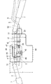
前輪操舵ユニット10は、一個の前輪24と前輪24の操舵システムとにより構成される。パイプ材からなる二本のハンドル軸25,25下端には前輪24を回転自在に軸架すると共に、その若干上方二ヶ所には平面視逆三角形状のブラケット26,26を夫々その底辺側を該二本のハンドル軸25,25に溶着し、その頂点側を後方へ突出させてある。27は軸受であり、サイドフレーム9,9前部の取付部11にキャスタ角を有して後傾して溶着してあり、軸受27上下面を上記、上下のブラケット26,26で挟み、該ブラケット26,26と軸受27を貫通する枢支軸28により前輪24を操舵可能に連結してある。
ハンドルポスト1は、アルミ製の鋳物で上下部材36,37に分割して構成され、その下部部材37には二本のハンドル軸25,25を挿通しネジ止めしてある。又、該ハンドルポスト1の上下部材36,37の合せ面には、バーハンドル2中央をUの字状に屈曲してその下部に形成される取付軸29と嵌合可能の嵌合溝30,30を幅方向に形成してあり、バーハンドル2の角度を調節可能に構成してある。
又、該取付軸29には下方に突出するピン31を設けるとともに、ハンドルポスト1の下部部材36の嵌合溝30中央に前後に形成する縦溝32と嵌合させ、該縦溝32の前後端によって、バーハンドル2の前後回動範囲を略々直立位置と後方の椅子16上面近傍位置との間に規制してある。
又、嵌合溝30,30の中央付近は若干肉取を行い、取付軸29回動時の摩擦抵抗を減少させてある。
ハンドルポスト1の下部部材36の前部両側部には、横方向に挿通孔33を形成する円筒部34,34を、又、該左右の円筒部34,34間には円筒凹部35を形成し、又、上部部材37の対向合せ面には、下部部材36に対応して中央に挿通孔33を有する円筒部34をその両側に円筒凹部35を形成すると共に、該上下部材36,37の合せ面を嵌合させ側方から挿通孔33,33内にピン38を挿通可能に構成してある。
又、上下部材36,37の後方側を突設し、これらを上下方向に貫通する通しボルト39を設けるとともに把手付ナット40で締付けることにより、上部部材36後部を前部のピン38を中心に回動させ、嵌合溝30,30に嵌合するバーハンドル取付軸29を締付固定可能に構成してある。
バーハンドル2は、前述の如く中央部をUの字状に屈曲し、中央部に大きなUの字状空間Aを形成し、その下部をその取付軸29をハンドルポスト1に回動自在に取着されるとともに、Uの字状屈曲部間上部を丸軸で形成される連結杆41で連結し、該連結杆41から左右の取付板42,42を固着して後方へ向け斜設垂下しその下部折曲部に操作ボックス3の下部ケース43をネジ止してある。
該左右の取付板42,42の上下略々中間部には、操作軸5を回動自在に保持させてある。
又、左側の取付板42は、前方に延設され、該延設部に電動車の速度指令信号を発生するポテンショメータ4を取着し、その軸に取軸のギヤ44と操作軸5に取着のギヤ45とを噛合させてある。又、操作軸5に取着のピン23と連結杆41の嵌合溝との間にはトルクスプリング46を巻装し、操作軸5を常にニュートラル位置であるストッパー47へ向け弾発してある。ストッパー47は、左側の取付板42前端から右方向に折曲される取付板48に取着されるボルトにて構成され、その接当位置を調節可能に構成してある。61は補強板であり、連結杆41と溶着し、下部ケース43とネジ止めしてある。
操作軸5は、バーハンドル2と略々一直線状に配置される連結杆41から後方に斜設される取付板42,42間に軸架されており、平面視バーハンドル2に対し操作軸5が後方側に位置しており、更にその両端を下部ケース43両側の通孔から操作ボックス3外へ突出させその延長部を前方外方へ屈曲させバーハンドル2の下方を迂回する槓杆6を形成し、更に外方上方へ向け屈曲させてグリップ7に沿うアクセルレバー8に構成してある。従って、操作装置がバーハンドル2,2の近傍でしかもその下方をも利用して配置され、槓杆6やアクセルレバー8の突出量を極力短く構成してあり、操縦者の乗降の際の接当や、他の障害物との接当を極力少なくでき安全である。なお、操作軸5は、操作ボックス3外方位置で槓杆6との間を分割して嵌合着脱自在に構成し、ボルト止めしてある。
又、アクセルレバー8はグリップ7の長さ方向内方側に接当させて、アクセルレバー8の最大操作位置を規制するストッパー機能を有させてあり、特別のストッパーを設ける必要がなく、又、比較的操作ボックス3から近い位置で規制する為、構成部材の製作誤差による回動範囲のバラツキを少なくできる。
更に、該アクセルレバー8は、グリップ7の長さの約内側半分で平行に接当させ、外側半分をグリップ7から離して回動範囲を規制するものであるから、その規制が確実であるとともに、グリップ7外側部をアクセルレバー8と共に握れば、アクセルレバー8が若干弾性力を有し、その操作フィーリングがよい。
操作ボックス3の下部ケース43は、平面視左側部分を前後方向に長く右側部分の前後幅を短く構成し、左側部分には連結杆41上に取付枠48を介してバッテリメータであるLEDランプを備える表示基板49を取着してある。下部ケース43は、下方を絞った漏斗状に形成すると共に、配線コードの挿通口50をその下部に設け、この挿通口50を排水および通気口としてある。
上記連結杆41の両側部には、環状溝51,51を形成し、操作ボックス3の上部ケース52と下部ケース43両側板に形成の半円状切欠部を上下から嵌合させ、雨水当の侵入を防止可能に構成してある。
上部ケース52は、下部ケース43と対応して、左側部分を前後方向に長く(L)、右側部分の前後幅を短く(l)、又、左右幅はそれらよりも長く横長状に形成して、バーハンドル2中央のUの字状空間A内にその主体部を下部ケース43と共に位置させてある。
53は、表示窓であり、上部ケース52の中央傾斜面54に位置して透明材で形成され、前記表示基板49上のLEDランプを目視可能に構成してある。
55は、最高速度設定用のノブであり、その回転操作によりポテンショメータ56を調節可能に構成してあり、又、57は前後進切替スイッチであり、これらは上部ケース52の左側部分の手前側上面に設けてある。
58は、キースイッチであり、上部ケース52の右側部分の手前側略垂直面に設けてある。従って、該上部ケース52の左側部分より突出することがなく、乗降時等にも支障となることがない。
59は、緊急停止スイッチであり、右側部分上面に設けられ、走行中に緊急停止を行う際に、操作を行うとモータ66への通電を断って電動車を停止可能に構成してある。又、該緊急停止スイッチ59を停止中に操作した場合には、モータ66軸に設ける電磁ブレーキを解除して手押し走行可能に構成してある。
この様に、各種操作スイッチを上部ケース52上面若しくは、突出しない位置に設けてあり、乗降の際等に支障となることがない。
後輪駆動ユニット13は、両サイドフレーム9,9と、補強パイプ60後部に溶着のL字型ブラケット12を介して、後輪63,63の車軸ケース64を取着してあり、該車軸ケース64中央にはデフ装置を内装するギヤボックス65とモータ66が一体に設けられている。
67は、バンパーであり、サイドフレーム9,9及びブラケット12,12に溶着され、後方に延出されると共に、その前後中間でギヤボックス65を支持させてある。68はバッテリ、69はコントローラ収納ケースであり、ステップ70下方に設けてある。
The front wheel steering unit 10 is composed of one front wheel 24 and a steering system for the front wheels 24. The front wheels 24 are rotatably mounted on the lower ends of the two handle shafts 25 and 25 made of pipe material, and the brackets 26 and 26 having an inverted triangular shape in a plan view are attached to the bottom two positions slightly above the front wheels 24, respectively. It is welded to the two handle shafts 25 and 25, and the apex side thereof is projected rearward. Reference numeral 27 denotes a bearing, which is welded to the mounting portion 11 at the front of the side frames 9 and 9 by tilting backward with a caster angle, and the upper and lower surfaces of the bearing 27 are sandwiched between the upper and lower brackets 26 and 26. The front wheels 24 are steerably connected by a pivot shaft 28 penetrating the brackets 26 and 26 and the bearing 27.
The handle post 1 is made of cast aluminum and is divided into upper and lower members 36 and 37, and two handle shafts 25 and 25 are inserted and screwed to the lower members 37 thereof. Further, on the mating surfaces of the upper and lower members 36 and 37 of the handle post 1, a fitting groove 30 which can be fitted with a mounting shaft 29 formed by bending the center of the bar handle 2 into a U shape and forming a lower portion thereof, 30 is formed in the width direction, and the angle of the bar handle 2 can be adjusted.
Further, the mounting shaft 29 is provided with a pin 31 projecting downward, and is fitted with a vertical groove 32 formed in the front and rear of the fitting groove 30 of the lower member 36 of the handle post 1 in the front and rear of the vertical groove 32. The front-rear rotation range of the bar handle 2 is restricted by the end between the substantially upright position and the position near the upper surface of the rear chair 16.
Further, the fitting grooves 30 and 30 are slightly lightened in the vicinity of the center to reduce the frictional resistance when the mounting shaft 29 is rotated.
Cylindrical portions 34, 34 forming insertion holes 33 in the lateral direction are formed on both front sides of the lower member 36 of the handle post 1, and cylindrical recesses 35 are formed between the left and right cylindrical portions 34, 34. Further, on the facing mating surface of the upper member 37, a cylindrical portion 34 having an insertion hole 33 in the center corresponding to the lower member 36 is formed on both sides thereof, and cylindrical recesses 35 are formed, and the upper and lower members 36 and 37 are aligned. The surfaces are fitted so that the pins 38 can be inserted into the insertion holes 33 and 33 from the side.
Further, by projecting the rear side of the upper and lower members 36 and 37, providing a through bolt 39 penetrating them in the vertical direction and tightening with a nut 40 with a handle, the rear part of the upper member 36 is centered on the front pin 38. The bar handle mounting shaft 29 that is rotated and fitted into the fitting grooves 30 and 30 is configured to be able to be tightened and fixed.
As described above, the bar handle 2 has its central portion bent in a U shape to form a large U-shaped space A in the central portion, and its mounting shaft 29 is rotatably attached to the handle post 1 at the lower portion thereof. At the same time, the upper part between the U-shaped bent portions is connected by a connecting rod 41 formed by a round shaft, and the left and right mounting plates 42 and 42 are fixed from the connecting rod 41 and slanted backward. The lower case 43 of the operation box 3 is screwed to the lower bent portion.
The operation shaft 5 is rotatably held in the upper and lower intermediate portions of the left and right mounting plates 42, 42.
Further, the mounting plate 42 on the left side is extended forward, and a potentiometer 4 for generating a speed command signal of an electric vehicle is attached to the extended portion, and a gear 44 for an axle and an operating axis 5 are attached to the extension. It is meshed with the wearing gear 45. Further, a torque spring 46 is wound around the operation shaft 5 between the attachment pin 23 and the fitting groove of the connecting rod 41, and the operation shaft 5 is always elastic toward the stopper 47 which is in the neutral position. The stopper 47 is composed of bolts attached to a mounting plate 48 that is bent to the right from the front end of the mounting plate 42 on the left side, and its contact position can be adjusted. Reference numeral 61 denotes a reinforcing plate, which is welded to the connecting rod 41 and screwed to the lower case 43.
The operation shaft 5 is pivotally mounted between the mounting plates 42 and 42 slanted rearward from the connecting lever 41 arranged substantially linearly with the bar handle 2, and the operation shaft 5 is mounted on the plan view bar handle 2 with respect to the operation shaft 5. Is located on the rear side, and both ends thereof are projected to the outside of the operation box 3 from the through holes on both sides of the lower case 43, and the extension portion thereof is bent forward and outward to form a lever 6 that bypasses the lower part of the bar handle 2. The accelerator lever 8 is further bent outward and upward along the grip 7. Therefore, the operating device is arranged in the vicinity of the bar handles 2 and 2 and also by utilizing the lower part thereof, and the protrusion amount of the lever 6 and the accelerator lever 8 is configured to be as short as possible. Also, it is safe because the contact with other obstacles can be minimized. The operation shaft 5 is divided between the operation shaft 5 and the lever 6 at an outer position of the operation box 3 so that it can be fitted and detached, and is bolted.
Further, the accelerator lever 8 is brought into contact with the inner side of the grip 7 in the length direction to have a stopper function for regulating the maximum operating position of the accelerator lever 8, and it is not necessary to provide a special stopper. Since the regulation is performed at a position relatively close to the operation box 3, the variation in the rotation range due to the manufacturing error of the constituent members can be reduced.
Further, since the accelerator lever 8 is brought into parallel contact with the inner half of the length of the grip 7 and the outer half is separated from the grip 7 to regulate the rotation range, the regulation is reliable. If the outer portion of the grip 7 is gripped together with the accelerator lever 8, the accelerator lever 8 has a slight elastic force, and its operation feeling is good.
The lower case 43 of the operation box 3 has a structure in which the left side portion in a plan view is long in the front-rear direction and the front-rear width of the right side portion is short, and an LED lamp which is a battery meter is mounted on the left side portion via a mounting frame 48 on the connecting rod 41. A display board 49 is attached. The lower case 43 is formed in a funnel shape with a narrowed downward portion, and an insertion port 50 for a wiring cord is provided below the insertion port 50, and the insertion port 50 is used as a drainage port and a ventilation port.
Circular grooves 51 and 51 are formed on both sides of the connecting rod 41, and semicircular notches formed in the upper case 52 and the lower case 43 both side plates of the operation box 3 are fitted from above and below to provide rainwater. It is configured to prevent intrusion.
Corresponding to the lower case 43, the upper case 52 is formed so that the left side portion is longer in the front-rear direction (L), the front-rear width of the right side portion is shorter (l), and the left-right width is longer than them in a horizontally long shape. , The main body thereof is positioned together with the lower case 43 in the U-shaped space A at the center of the bar handle 2.
Reference numeral 53 denotes a display window, which is located on the central inclined surface 54 of the upper case 52 and is formed of a transparent material so that the LED lamp on the display board 49 can be visually recognized.
Reference numeral 55 denotes a knob for setting the maximum speed, the potentiometer 56 is configured to be adjustable by the rotation operation thereof, and 57 is a forward / backward changeover switch, which are the upper surface on the front side of the left side portion of the upper case 52. It is provided in.
Reference numeral 58 denotes a key switch, which is provided on a substantially vertical surface on the front side of the right side portion of the upper case 52. Therefore, it does not protrude from the left side portion of the upper case 52 and does not hinder getting on and off.
Reference numeral 59 denotes an emergency stop switch, which is provided on the upper surface of the right side portion, and is configured to be able to stop the electric vehicle by cutting off the power supply to the motor 66 when the operation is performed when the emergency stop is performed during traveling. Further, when the emergency stop switch 59 is operated while stopped, the electromagnetic brake provided on the motor 66 shaft is released so that the vehicle can be pushed by hand.
In this way, various operation switches are provided on the upper surface of the upper case 52 or at a position where they do not protrude, so that they do not interfere with getting on and off.
The rear wheel drive unit 13 has the axle cases 64 of the rear wheels 63 and 63 attached to both side frames 9 and 9 and the rear portion of the reinforcing pipe 60 via a welded L-shaped bracket 12. At the center of 64, a gear box 65 containing a differential device and a motor 66 are integrally provided.
Reference numeral 67 denotes a bumper, which is welded to the side frames 9 and 9 and the brackets 12 and 12 and extends rearward, and supports the gearbox 65 in the middle of the front and rear thereof. 68 is a battery, 69 is a controller storage case, and is provided below step 70.