FR2819280A1 - Log for construction of wooden chalet walls comprises two right angled triangle sections fitted together along respective hypotenuse to form external and internal wall portions - Google Patents
Log for construction of wooden chalet walls comprises two right angled triangle sections fitted together along respective hypotenuse to form external and internal wall portions Download PDFInfo
- Publication number
- FR2819280A1 FR2819280A1 FR0100125A FR0100125A FR2819280A1 FR 2819280 A1 FR2819280 A1 FR 2819280A1 FR 0100125 A FR0100125 A FR 0100125A FR 0100125 A FR0100125 A FR 0100125A FR 2819280 A1 FR2819280 A1 FR 2819280A1
- Authority
- FR
- France
- Prior art keywords
- log
- logs
- wooden
- wall
- bearing surface
- Prior art date
- Legal status (The legal status is an assumption and is not a legal conclusion. Google has not performed a legal analysis and makes no representation as to the accuracy of the status listed.)
- Withdrawn
Links
Classifications
-
- E—FIXED CONSTRUCTIONS
- E04—BUILDING
- E04B—GENERAL BUILDING CONSTRUCTIONS; WALLS, e.g. PARTITIONS; ROOFS; FLOORS; CEILINGS; INSULATION OR OTHER PROTECTION OF BUILDINGS
- E04B2/00—Walls, e.g. partitions, for buildings; Wall construction with regard to insulation; Connections specially adapted to walls
- E04B2/56—Load-bearing walls of framework or pillarwork; Walls incorporating load-bearing elongated members
- E04B2/70—Load-bearing walls of framework or pillarwork; Walls incorporating load-bearing elongated members with elongated members of wood
- E04B2/701—Load-bearing walls of framework or pillarwork; Walls incorporating load-bearing elongated members with elongated members of wood with integrated supporting and obturation function
- E04B2/705—Load-bearing walls of framework or pillarwork; Walls incorporating load-bearing elongated members with elongated members of wood with integrated supporting and obturation function with longitudinal horizontal elements placed between columns
Abstract
Description
<Desc/Clms Page number 1> <Desc / Clms Page number 1>
La présente invention concerne la conception et la réalisation de constructions en bois. Les parois des constructions en bois, telles que des chalets, sont généralement réalisées par un empilement vertical d'éléments de construction longitudinaux ayant la forme générale d'une poutre que l'on appelle rondin. The present invention relates to the design and production of wooden constructions. The walls of wooden constructions, such as chalets, are generally produced by a vertical stack of longitudinal construction elements having the general shape of a beam which is called a log.
Les maisons d'habitation en bois dont les murs sont réalisés par empilage de rondins ont beaucoup de cachet et elles présentent de bonnes propriétés isolantes, avec en particulier une bonne qualité d'isolation thermique, mais elles présentent aussi un certain nombre d'inconvénients. Wooden dwelling houses whose walls are made by stacking logs have a lot of character and they have good insulating properties, with in particular a good quality of thermal insulation, but they also have a certain number of drawbacks.
Tout d'abord, elles n'assurent qu'un très faible degré de sécurité contre l'intrusion, puisqu'il suffit d'utiliser un outil de découpe du bois tel qu'une tronçonneuse pour pénétrer dans ces habitations. Par ailleurs, le profil extérieur des murs en rondins est tel qu'il est facile d'escalader de telles maisons. First of all, they only provide a very low degree of security against intrusion, since it suffices to use a wood cutting tool such as a chainsaw to enter these dwellings. Furthermore, the exterior profile of the log walls is such that it is easy to climb such houses.
D'autre part, la réalisation de construction en bois doit tenir compte du phénomène de retrait du bois, pour des raisons climatiques ou pour des raisons de vieillissement, d'où il peut résulter des imperfections tant sur le plan esthétique que sur le plan du pouvoir isolant des murs. On the other hand, the realization of wooden construction must take into account the phenomenon of shrinkage of the wood, for climatic reasons or for reasons of aging, from which it can result from imperfections both on the aesthetic plan and on the plan. insulating power of walls.
D'autres inconvénients concernent le montage de murs ou parois avec des rondins de type connu, qui est relativement complexe et long du fait qu'il nécessite un positionnement précis et le maintien des rondins. Other disadvantages relate to the mounting of walls or walls with logs of known type, which is relatively complex and long because it requires precise positioning and the maintenance of the logs.
On peut souligner aussi que la nature du bois est habituellement choisie essentiellement pour résister aux agressions extérieures, si bien que le bois choisi n'a pas toujours un aspect esthétique très agréable pour l'intérieur d'une maison d'habitation. It can also be emphasized that the nature of the wood is usually chosen essentially to resist external aggressions, so that the wood chosen does not always have a very pleasant aesthetic appearance for the interior of a dwelling house.
Les habitants peuvent alors être amenés à ajouter des revêtements intérieurs plus agréables, ce qui augmente le coût. Il est également difficile de lutter contre la pénétration de la pluie, et les fuites ne sont pas rares dans le cas de pluies battantes. Enfin, lorsqu'un feu attaque la partie extérieure d'une paroi, il se propage très Residents may then have to add more pleasant interior coverings, which increases the cost. It is also difficult to combat the penetration of rain, and leaks are not uncommon in the case of heavy rain. Finally, when a fire attacks the outside of a wall, it spreads very
<Desc/Clms Page number 2><Desc / Clms Page number 2>
rapidement à l'intérieur de l'habitation dans la mesure où l'intégralité du mur est en bois. quickly inside the house since the entire wall is made of wood.
La présente invention se propose de fournir un rondin pour la réalisation, par empilement vertical, de parois ou de murs en bois qui permet de supprimer les inconvénients des solutions existantes, parmi lesquels ceux précités. The present invention proposes to provide a log for the realization, by vertical stacking, of wooden walls or walls which makes it possible to eliminate the drawbacks of the existing solutions, among which those mentioned above.
Un rondin suivant l'invention est notamment remarquable en ce qu'il est constitué en deux parties, par deux pièces en bois qui ont en section sensiblement la forme d'un triangle rectangle et qui s'assemblent par emboîtement l'une sur l'autre le long de leur hypoténuse suivant des faces diagonales respectives, à savoir une pièce extérieure présentant une portion de mur extérieur et une surface d'appui inférieure et une pièce intérieure présentant une portion de mur intérieur et une surface d'appui supérieure, une plaque métallique étant en outre prévu pour être interposée en pièce intermédiaire entre lesdites faces diagonales des deux pièces en bois du rondin. A log according to the invention is notably remarkable in that it is made up of two parts, by two wooden pieces which have a cross-section substantially in the shape of a right triangle and which are assembled by interlocking one on the other along their hypotenuse along respective diagonal faces, namely an outer part having an outer wall portion and a lower bearing surface and an inner part having an inner wall portion and an upper bearing surface, a plate being also made of metal to be interposed as an intermediate piece between said diagonal faces of the two wooden pieces of the log.
De cette manière, le retrait du bois est absorbé par chacune des pièces de bois, ce qui permet de limiter son effet. Par ailleurs, la plaque métallique constitue une sécurité contre l'intrusion au moyen d'un outil de découpe du bois. L'assemblage par emboîtement permet de faciliter le montage et la réalisation de parois en bois par empilement vertical de rondins successifs. Dans un tel empilement la surface d'appui inférieure de la pièce extérieure de chaque rondin se dispose sensiblement horizontale en coopération avec la surface d'appui supérieure de la pièce intérieure d'un rondin adjacent précédent, qui se dispose également sensiblement horizontale et sur laquelle elle vient reposer. In this way, the shrinkage of the wood is absorbed by each of the pieces of wood, which limits its effect. Furthermore, the metal plate constitutes a security against intrusion by means of a wood cutting tool. The interlocking assembly makes it easier to assemble and produce wooden walls by vertical stacking of successive logs. In such a stack, the lower bearing surface of the outer part of each log is arranged substantially horizontal in cooperation with the upper bearing surface of the inner part of a previous adjacent log, which is also arranged substantially horizontal and on which she comes to rest.
La réalisation du rondin en deux parties essentielles permet d'avoir deux formes différentes entre l'intérieur et l'extérieur du mur et offre la possibilité d'utiliser des essences de bois différentes pour les deux pièces de bois du rondin. En particulier, on peut réaliser une des parties, la pièce intérieure, au moyen de bois lamellé collé ou autres variétés de bois reconstitué qui seraient trop fragiles à l'extérieur, ce qui permet, en faisant varier les différentes The realization of the log in two essential parts allows to have two different shapes between the inside and the outside of the wall and offers the possibility of using different wood essences for the two pieces of wood of the log. In particular, one of the parts, the interior part, can be produced using glued laminated wood or other varieties of reconstituted wood which would be too fragile on the outside, which makes it possible, by varying the different
<Desc/Clms Page number 3><Desc / Clms Page number 3>
essences de bois ainsi que les épaisseurs des lames de bois et des couches de colle, de produire des aspects décoratifs. wood species as well as the thicknesses of the wooden blades and the layers of glue, to produce decorative aspects.
On notera aussi que la présence de la plaque métallique augmente la rigidité du rondin, en empêchant le travail du bois en courbe et l'écrasement des fibres du bois. Par ailleurs, elle s'oppose à la propagation du feu d'un côté du mur à l'autre. It will also be noted that the presence of the metal plate increases the rigidity of the log, preventing the working of curved wood and the crushing of the wood fibers. Furthermore, it opposes the spread of fire from one side of the wall to the other.
Conformément à des modes de réalisation avantageux du rondin suivant l'invention, la surface d'appui supérieure du rondin et la surface d'appui inférieure du rondin disposée au-dessus sont bloquées l'une sur l'autre par emboîtement. De ce fait, il n'est pas nécessaire de prévoir des moyens de fixation et de blocage des rondins l'un sur l'autre, ce blocage étant obtenu de manière automatique par emboîtement. According to advantageous embodiments of the log according to the invention, the upper bearing surface of the log and the lower bearing surface of the log disposed above are locked one on the other by interlocking. Therefore, it is not necessary to provide means for fixing and blocking the logs one on the other, this blocking being obtained automatically by interlocking.
Selon une autre caractéristique de l'invention, la portion de mur extérieur présente, en section, une forme arrondie qui comporte une partie inférieure en surplomb. Cela facilite l'évacuation de la pluie, du fait que les gouttes d'eau qui coulent sur chaque rondin tombent de l'arête curviligne qui précède ce surplomb et ne s'écoulent pas plus loin le long de ce dernier en ayant tendance à pénétrer dans le mur. According to another characteristic of the invention, the exterior wall portion has, in section, a rounded shape which includes an overhanging lower part. This facilitates the evacuation of the rain, because the drops of water which flow on each log fall from the curvilinear edge which precedes this overhang and do not flow further along this last while having a tendency to penetrate in the wall.
Selon un mode de réalisation préféré de l'invention, la plaque métallique est divisée longitudinalement en deux sections dont les bords disposés à l'intérieur du rondin sont en recouvrement. Cette réalisation en deux sections, ou ailes, permet de mieux absorber les mouvements de retrait du bois. Dans ce cas il est avantageux de prévoir la zone de recouvrement entre les deux ailes au fond de la rainure d'emboîtement des pièces en bois, ce qui notamment facilite l'assemblage par empilement des différents éléments constitutifs de rondins successifs. According to a preferred embodiment of the invention, the metal plate is divided longitudinally into two sections whose edges disposed inside the log are overlapped. This realization in two sections, or wings, allows to better absorb the movements of withdrawal of the wood. In this case it is advantageous to provide the overlap zone between the two wings at the bottom of the interlocking groove of the wooden parts, which in particular facilitates the assembly by stacking of the various components of successive logs.
Selon une autre caractéristique de l'invention, la plaque métallique comporte un revêtement d'isolation thermique de manière à améliorer le coefficient d'isolation thermique de l'ensemble du mur. Avantageusement, ce revêtement est en liège, ce matériau According to another characteristic of the invention, the metal plate comprises a thermal insulation coating so as to improve the coefficient of thermal insulation of the entire wall. Advantageously, this covering is made of cork, this material
<Desc/Clms Page number 4><Desc / Clms Page number 4>
représentant un matériau isolant qui, en outre, n'émet pas de gaz toxiques lors de sa combustion. representing an insulating material which, in addition, does not emit toxic gases during its combustion.
Selon encore une autre caractéristique de l'invention, la plaque métallique comporte un prolongement recouvrant partiellement la portion de mur extérieur. Ce prolongement a avantageusement la forme d'une équerre. Il permet tout d'abord de masquer des retraits éventuels du bois ; par ailleurs, il permet l'évacuation de l'eau sur la face extérieure, car ce prolongement arrête la goutte d'eau en cas de grands vents et crée à l'intérieur une petite chambre de décompression. According to yet another characteristic of the invention, the metal plate has an extension partially covering the portion of the exterior wall. This extension advantageously has the shape of a square. First of all, it conceals any shrinkage of the wood; in addition, it allows the evacuation of water on the outside, because this extension stops the drop of water in the event of strong winds and creates inside a small decompression chamber.
Dans des modes de mise en oeuvre préférés de l'invention, au moins une des deux pièces de bois du rondin est réalisée en bois lamellé collé. Dans ce cas, et notamment quand la pièce intérieure répond à une conception en bois lamellé collé, cela offre de larges possibilités de composition et de décoration, tant par le choix des essences de bois (couleurs et épaisseurs variables pour une même densité) que par celui du joint ou de la colle (variations de couleur et d'épaisseur). Par ailleurs, l'utilisation de bois lamellé collé permet de réduire notablement le retrait du rondin. In preferred embodiments of the invention, at least one of the two pieces of wood from the log is made of glued laminated wood. In this case, and in particular when the interior piece responds to a glued laminated wood design, this offers wide possibilities of composition and decoration, both by the choice of wood species (colors and thicknesses varying for the same density) as by that of the joint or glue (variations in color and thickness). In addition, the use of glued laminated timber significantly reduces shrinkage of the log.
L'invention a également pour objet une structure de mur en bois réalisée avec des rondins répondant à une ou plusieurs des particularités précitées. Une telle structure est notamment caractérisée en ce que les extrémités d'au moins une partie des rondins sont montées à coulissement dans des poteaux porteurs comportant une gorge longitudinale ménagée à cet effet. De ce fait, au moins une partie de chaque rondin est bloqué latéralement dans les poteaux porteurs, ce qui assure une mise en place et un maintien en position automatiques des rondins. The invention also relates to a wooden wall structure produced with logs meeting one or more of the above-mentioned features. Such a structure is particularly characterized in that the ends of at least part of the logs are slidably mounted in support posts having a longitudinal groove made for this purpose. As a result, at least a part of each log is blocked laterally in the support posts, which ensures that the logs are automatically placed and maintained in position.
Les deux parties des rondins comporte au moins un trou ou une gorge vertical, les trous ou gorges des deux parties s'alignant verticalement dans l'empilement, et les rondins sont enfilés sur au moins un poteau intermédiaire traversant l'empilement dans lesdits trous ou gorges. The two parts of the logs have at least one vertical hole or groove, the holes or grooves of the two parts aligning vertically in the stack, and the logs are threaded on at least one intermediate post passing through the stack in said holes or gorges.
<Desc/Clms Page number 5> <Desc / Clms Page number 5>

Grâce à ces dispositions, on peut insérer, de manière non visible, des poteaux intermédiaires qui permettent de supporter l'effort de la poutre sablière disposée au-dessus du mur en cas d'un éventuel retrait du bois du mur. Ces poteaux intermédiaires peuvent être en métal, par exemple notamment en acier inoxydable. Thanks to these provisions, it is possible to insert, in a non-visible manner, intermediate posts which make it possible to support the force of the sand beam placed above the wall in the event of a possible withdrawal of the wood from the wall. These intermediate posts can be made of metal, for example in particular stainless steel.
Avantageusement, une lame métallique verticale formant joint est disposée sur le bord extérieur des poteaux porteurs à gorge. Cette lame métallique constitue une protection contre la pénétration de la pluie en cas de vent violent. Advantageously, a vertical metal blade forming a seal is arranged on the outer edge of the support posts with grooves. This metal blade provides protection against the penetration of rain in strong winds.
L'invention sera maintenant plus complètement décrite dans le cadre de caractéristiques préférées et de leurs avantages, en faisant référence aux figures et dessins annexés qui les illustrent et dans lesquels : - la figure 1 est une vue en coupe représentant deux rondins selon l'invention assemblés l'un sur l'autre, chacun étant constitué de deux parties ou pièces coopérantes ; - la figure 2 représente en perspective la pièce constituant une partie extérieure de rondin ; - la figure 3 est une vue en perspective de la pièce constituant une partie intérieure de rondin ; - la figure 4 est une vue en perspective d'un rondin complet constitué par assemblage des deux éléments que constituent respectivement une pièce de partie extérieure et une pièce de partie intérieure, avec en outre interposition d'une plaque intermédiaire suivant leurs faces diagonales coopérantes ; - la figure 5 représente en perspective une structure de mur réalisée par empilement de rondins selon l'invention entre deux poteaux porteurs ; - la figure 6 représente en perspective un tel mur en cours de construction dans le cas où celui-ci comporte un poteau intermédiaire entre les deux poteaux porteurs ; - la figure 7 représente en perspective l'un des poteaux porteurs servant à la construction d'un tel mur ; The invention will now be more fully described in the context of preferred characteristics and their advantages, with reference to the appended figures and drawings which illustrate them and in which: - Figure 1 is a sectional view showing two logs according to the invention assembled one on the other, each consisting of two cooperating parts or parts; - Figure 2 shows in perspective the part constituting an outer part of the log; - Figure 3 is a perspective view of the part constituting an inner part of the log; - Figure 4 is a perspective view of a complete log formed by assembling the two elements that respectively constitute an outer part part and an inner part part, with further interposition of an intermediate plate along their cooperating diagonal faces; - Figure 5 shows in perspective a wall structure produced by stacking logs according to the invention between two load-bearing posts; - Figure 6 shows in perspective such a wall under construction in the case where it comprises an intermediate post between the two supporting posts; - Figure 7 shows in perspective one of the supporting posts used for the construction of such a wall;
<Desc/Clms Page number 6> <Desc / Clms Page number 6>
- la figure 8 est une vue de détail en partie haute de la figure 7, faisant apparaître la forme d'une lame formant joint ; - les figures 9 à 11 montrent des représentations en perspective qui illustrent le montage d'un mur réalisé par empilement de rondins selon l'invention, ; - la figure 12 est une vue en perspective de plaques métalliques venant s'interposer entre les deux pièces de bois constitutives d'un rondin ; - et la figure 13 est une de détail de la figure 12 montrant deux ailes de plaque intermédiaire en recouvrement l'une sur l'autre.
- Figure 8 is a detail view in the upper part of Figure 7, showing the shape of a blade forming a seal; - Figures 9 to 11 show perspective representations which illustrate the mounting of a wall produced by stacking logs according to the invention,; - Figure 12 is a perspective view of metal plates interposed between the two pieces of wood constituting a log; - And Figure 13 is a detail of Figure 12 showing two intermediate plate wings overlapping one on the other.
L'invention est décrite ci-après en se référant à la construction d'un mur extérieur d'une habitation en bois, mais elle n'est pas limitée à ce mode de réalisation ; elle peut également s'appliquer à la réalisation de murs de clôture par exemple. The invention is described below with reference to the construction of an exterior wall of a wooden dwelling, but it is not limited to this embodiment; it can also apply to the construction of enclosure walls for example.
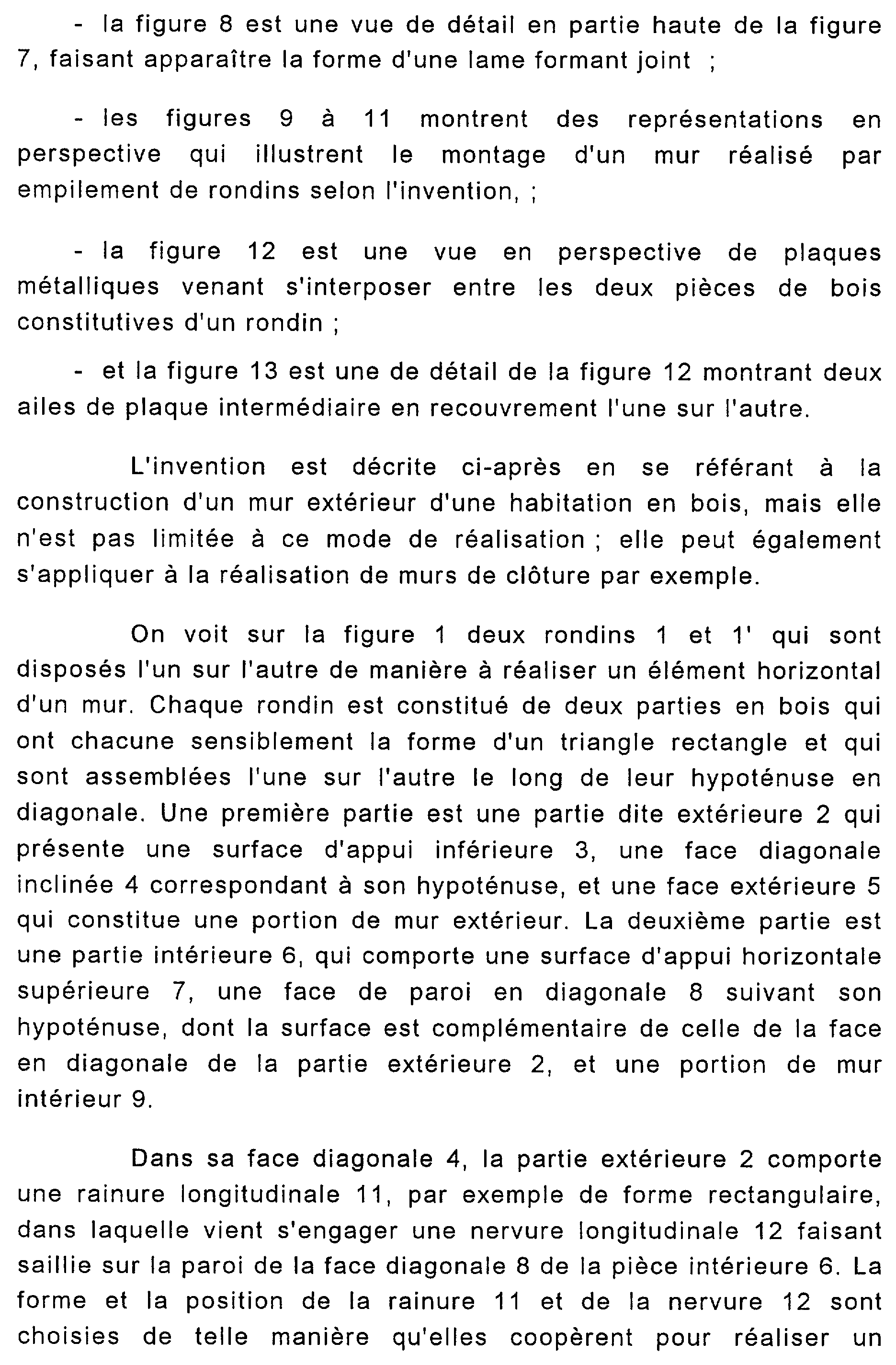
On voit sur la figure 1 deux rondins 1 et l'qui sont disposés l'un sur l'autre de manière à réaliser un élément horizontal d'un mur. Chaque rondin est constitué de deux parties en bois qui ont chacune sensiblement la forme d'un triangle rectangle et qui sont assemblées l'une sur l'autre le long de leur hypoténuse en diagonale. Une première partie est une partie dite extérieure 2 qui présente une surface d'appui inférieure 3, une face diagonale inclinée 4 correspondant à son hypoténuse, et une face extérieure 5 qui constitue une portion de mur extérieur. La deuxième partie est une partie intérieure 6, qui comporte une surface d'appui horizontale supérieure 7, une face de paroi en diagonale 8 suivant son hypoténuse, dont la surface est complémentaire de celle de la face en diagonale de la partie extérieure 2, et une portion de mur intérieur 9. We see in Figure 1 two logs 1 and the which are arranged one on the other so as to produce a horizontal element of a wall. Each log consists of two wooden parts which each have substantially the shape of a right triangle and which are assembled one on the other along their hypotenuse diagonally. A first part is a so-called external part 2 which has a lower bearing surface 3, an inclined diagonal face 4 corresponding to its hypotenuse, and an external face 5 which constitutes a portion of the external wall. The second part is an inner part 6, which has an upper horizontal bearing surface 7, a diagonal wall face 8 along its hypotenuse, the surface of which is complementary to that of the diagonal face of the outer part 2, and a portion of interior wall 9.
Dans sa face diagonale 4, la partie extérieure 2 comporte une rainure longitudinale 11, par exemple de forme rectangulaire, dans laquelle vient s'engager une nervure longitudinale 12 faisant saillie sur la paroi de la face diagonale 8 de la pièce intérieure 6. La forme et la position de la rainure 11 et de la nervure 12 sont choisies de telle manière qu'elles coopèrent pour réaliser un In its diagonal face 4, the outer part 2 has a longitudinal groove 11, for example of rectangular shape, in which engages a longitudinal rib 12 projecting from the wall of the diagonal face 8 of the inner part 6. The shape and the position of the groove 11 and the rib 12 are chosen in such a way that they cooperate to produce a
<Desc/Clms Page number 7><Desc / Clms Page number 7>
blocage par emboîtement de la pièce intérieure 6 dans la pièce extérieure 2. locking by fitting of the inner part 6 into the outer part 2.
De manière analogue, la face d'appui inférieure 3 de la pièce extérieure 2 comporte une nervure longitudinale 13 qui présente en section une forme complémentaire de celle d'une encoche ou rainure longitudinale 14 qui est ménagée dans la surface d'appui 7 supérieure de la partie extérieure 6. La forme et la position de la nervure 13 et de la rainure 14 sont déterminées de manière à faire coopérer par elles deux rondins superposés 1 et 1', la nervure de la partie supérieure 2'du rondin l'se fixant par emboîtement dans la rainure de la partie inférieure 6 du rondin 1. Similarly, the lower bearing face 3 of the outer part 2 comprises a longitudinal rib 13 which has in section a shape complementary to that of a notch or longitudinal groove 14 which is formed in the upper bearing surface 7 of the outer part 6. The shape and position of the rib 13 and the groove 14 are determined so as to make them cooperate with two superimposed logs 1 and 1 ', the rib of the upper part 2' of the log securing it by fitting into the groove of the lower part 6 of the log 1.
Dans cette position des deux rondins reposant l'un sur l'autre, les surfaces d'appui respectives sont orientées horizontalement. Les deux faces qui constituent sur chaque rondin les portions de mur 5 et 9 sont alors sensiblement verticales. Toutefois ces faces 5 et 9 des deux parties 1 et 2 ont une forme arrondie. In this position of the two logs resting on each other, the respective bearing surfaces are oriented horizontally. The two faces which constitute the wall portions 5 and 9 on each log are then substantially vertical. However, these faces 5 and 9 of the two parts 1 and 2 have a rounded shape.
De plus, la face 5 formant une portion de paroi de mur extérieure présente un rayon de courbure faible, de telle manière que l'on obtient, en dessous d'une arête extérieure arrondie 15, une partie en surplomb 16 par rapport à la surface d'appui inférieure correspondante. De ce fait, les gouttes d'eau qui coulent le long de la paroi extérieure du mur tombent lorsqu'elles parviennent à l'arête 15 d'un rondin, sans glisser le long de la partie en surplomb 16. In addition, the face 5 forming a portion of the outer wall wall has a small radius of curvature, so that there is obtained, below a rounded outer edge 15, an overhanging part 16 relative to the surface. corresponding lower support. As a result, the drops of water flowing along the outer wall of the wall fall when they reach the edge 15 of a log, without sliding along the overhanging part 16.
L'eau ne peut donc pénétrer entre les deux rondins 1 et 1'. Par ailleurs, il n'y a pas de possibilité de prise pour une personne tentant d'escalader le mur. Water cannot therefore penetrate between the two logs 1 and 1 '. In addition, there is no possibility of catch for a person trying to climb the wall.
Entre la pièce extérieure 2 et la pièce intérieure 6 qui constituent les deux pièces en bois d'un même rondin, il est interposé une pièce intermédiaire, constituée par une plaque métallique qui s'étend tout le long des faces diagonales 4 et 8, en épousant la forme de la rainure 11 et de la nervure 12. Cette plaque métallique est avantageusement réalisée au moyen de deux sections ou ailes 17 et 18 (voir figures 12 et 13) qui se rejoignent le long d'une ligne horizontale, de préférence au niveau de la rainure 11 et Between the outer part 2 and the inner part 6 which constitute the two wooden parts of the same log, there is interposed an intermediate part, constituted by a metal plate which extends all along the diagonal faces 4 and 8, in conforming to the shape of the groove 11 and the rib 12. This metal plate is advantageously produced by means of two sections or wings 17 and 18 (see FIGS. 12 and 13) which join together along a horizontal line, preferably at level of groove 11 and
<Desc/Clms Page number 8><Desc / Clms Page number 8>
de la nervure 12. Avantageusement, ces deux ailes de plaque intermédiaire 17 et 18 sont en recouvrement l'une sur l'autre, et ce de préférence dans le fond de la rainure 11. Pour éviter des différences d'épaisseur, les extrémités du bord 19 de l'aile 17 et du bord 21 de l'aile 18 qui se trouvent superposées au fond de la rainure 11 ont une épaisseur égale à la moitié de l'épaisseur du reste des ailes 17 et 18. of the rib 12. Advantageously, these two intermediate plate wings 17 and 18 are overlapped one on the other, and this preferably in the bottom of the groove 11. To avoid differences in thickness, the ends of the edge 19 of wing 17 and edge 21 of wing 18 which are superimposed on the bottom of groove 11 have a thickness equal to half the thickness of the rest of the wings 17 and 18.
La plaque 17-18 comporte, à l'extérieur des faces diagonales en vis-à-vis 4 et 8, un prolongement 22 qui a la forme d'une équerre (fig. 1). L'extrémité libre de la plaque 18, c'est-à-dire le petit côté de l'équerre 22, est en contact avec la face arrondie de la portion de mur constituée par la partie de rondin extérieure 2. De la sorte, le prolongement 22 de la plaque 18 permet d'arrêter les gouttes d'eau projetées en cas de grand vent. Il a aussi pour effet de créer, entre la portion de paroi extérieure 5 de la pièce extérieure 2 et le prolongement 22, une petite chambre de décompression 10 qui contribue à éviter la pénétration de l'eau de pluie entre les deux rondins 1 et 1'. The plate 17-18 has, on the outside of the diagonal faces opposite 4 and 8, an extension 22 which has the shape of a square (fig. 1). The free end of the plate 18, that is to say the short side of the bracket 22, is in contact with the rounded face of the wall portion formed by the outer log part 2. In this way, the extension 22 of the plate 18 makes it possible to stop the drops of water projected in the event of a strong wind. It also has the effect of creating, between the outer wall portion 5 of the outer part 2 and the extension 22, a small decompression chamber 10 which contributes to preventing the penetration of rainwater between the two logs 1 and 1 .
La face inférieure d'appui 3 de la pièce extérieure 2 comporte un évidement longitudinal 23 dont les dimensions correspondent au prolongement 22 de l'aile 18, laquelle vient se loger dans cet évidement lorsque deux rondins sont assemblés, comme représenté sur la figure 1. The lower support face 3 of the outer part 2 has a longitudinal recess 23 whose dimensions correspond to the extension 22 of the wing 18, which is housed in this recess when two logs are assembled, as shown in FIG. 1.
On voit sur la figure 4, représenté partiellement en perspective, un rondin selon l'invention tel qu'il se dispose après l'assemblage de la pièce intérieure 6 sur la pièce extérieure 2 et avant son assemblage avec un autre rondin similaire. We see in Figure 4, partially shown in perspective, a log according to the invention as it is arranged after the assembly of the inner part 6 on the outer part 2 and before its assembly with another similar log.
Pour réaliser un mur, les rondins 1, tous constitués comme les rondins 1 et l'de la figure 1, sont montés et assemblés les uns sur les autres comme représenté sur les figures 5 et 6. Les extrémités des parties extérieures 2 des rondins 1 sont montées à coulissement dans deux poteaux porteurs 25 qui forment l'encadrement du mur et dans lesquels il est ménagé une gorge longitudinale 24 à cet effet. On voit sur la figure 5 une poutre sablière 26 qui est disposée sur le dessus de la pile de rondins pour To make a wall, the logs 1, all made up like the logs 1 and the one in FIG. 1, are mounted and assembled one on the other as shown in FIGS. 5 and 6. The ends of the outer parts 2 of the logs 1 are slidably mounted in two support posts 25 which form the frame of the wall and in which a longitudinal groove 24 is provided for this purpose. We see in Figure 5 a sand beam 26 which is arranged on top of the stack of logs for
<Desc/Clms Page number 9><Desc / Clms Page number 9>
terminer le mur. Un module de base 27, de section rectangulaire, est disposé sur le sol en dessous du premier rondin de l'empilement constituant le mur. La forme de ce module évite que les eaux de ruissellement du mur ne soient absorbées entre le mur et le sol. finish the wall. A base module 27, of rectangular section, is placed on the ground below the first log of the stack constituting the wall. The shape of this module prevents the wall runoff from being absorbed between the wall and the ground.
On voit également sur la figure 6 un poteau intermédiaire 28, qui est fixé sur le sol au moyen d'une platine 29 et qui traverse le module de base 27 et l'ensemble des rondins 1. A cet effet, la pièce extérieure 2 comporte un trou vertical 31 et la pièce intérieure 6 comporte une gorge verticale 32. Par ailleurs, l'aile supérieure 18 de la plaque de protection contre l'intrusion comporte un trou 38 de section oblongue dans le sens transversal de l'aile 18. Les trous 31 38 et les gorges 32 sont alignés comme représenté sur les figures 1 à 3. Plus précisément, les différents trous et gorges des pièces extérieures et intérieures et des ailes supérieures 18 des différents rondins s'alignent dans l'empilement suivant une droite verticale pour recevoir le poteau intermédiaire 28. Ce dernier soutient la poutre sablière 26. On peut prévoir, si la longueur du mur est importante, plusieurs poteaux intermédiaires de renforcement 28 de ce type. Also seen in Figure 6 an intermediate post 28, which is fixed to the ground by means of a plate 29 and which passes through the base module 27 and all the logs 1. For this purpose, the outer part 2 comprises a vertical hole 31 and the inner part 6 has a vertical groove 32. Furthermore, the upper wing 18 of the intrusion protection plate has a hole 38 of oblong section in the transverse direction of the wing 18. The holes 31 38 and the grooves 32 are aligned as shown in FIGS. 1 to 3. More specifically, the different holes and grooves of the external and internal parts and of the upper flanges 18 of the various logs are aligned in the stack along a vertical line to receive the intermediate post 28. The latter supports the sand beam 26. It is possible to provide, if the length of the wall is large, several intermediate reinforcing posts 28 of this type.
La figure 7 représente en perspective un poteau porteur 25. FIG. 7 is a perspective view of a support post 25.
On peut notamment y voir la gorge 24, qui s'étend verticalement, et un épaulement 33 qui sert à recevoir la poutre sablière 26. Par ailleurs, on prévoit, sur la face 34 du poteau porteur 25 qui est dirigée vers l'extérieur, un joint 35 qui est placé sur l'arête extérieure du poteau porteur 25. Enfin, chaque poteau porteur 25 est réalisé en deux parties verticales entre lesquelles est interposée, sur toute la hauteur du poteau, une plaque métallique 30 qui sert de protection contre l'intrusion comme les deux ailes 17 et 18 de la plaque métallique interposée entre les deux parties de chaque rondin. We can see in particular the groove 24, which extends vertically, and a shoulder 33 which serves to receive the sand beam 26. Furthermore, provision is made on the face 34 of the support post 25 which is directed outwards, a seal 35 which is placed on the outer edge of the support post 25. Finally, each support post 25 is made in two vertical parts between which is interposed, over the entire height of the post, a metal plate 30 which serves as protection against the 'intrusion like the two wings 17 and 18 of the metal plate interposed between the two parts of each log.
Comme on peut le voir en particulier sur la figure 8, qui est une vue de détail montrant le haut de la gorge 24, le joint 35 est une lame métallique constituée par un profilé dont la section en partie courante a la forme générale d'un T dont la barre horizontale vient recouvrir le bord de la face 34 du poteau porteur 25 et l'extrémité As can be seen in particular in FIG. 8, which is a detail view showing the top of the groove 24, the seal 35 is a metal strip formed by a profile, the cross section of which in common part has the general shape of a T whose horizontal bar covers the edge of the face 34 of the support post 25 and the end
<Desc/Clms Page number 10><Desc / Clms Page number 10>
des rondins 1. Ce joint 35 est en métal, de préférence en acier inoxydable. Il permet de masquer les conséquences d'un éventuel retrait du bois des rondins 1. logs 1. This seal 35 is made of metal, preferably stainless steel. It masks the consequences of a possible removal of the wood from the logs 1.
Les plaques métalliques 17 et 18 comportent, sur leurs faces supérieures, un revêtement 20 qui est constitué en un matériau isolant du point de vue thermique, tel que du liège, et qui est appliqué sur la face supérieure des deux plaques 17 et 18 (voir figures 12 et 13). Cette disposition permet d'améliorer le coefficient d'isolation thermique du mur, sans introduire de matières pouvant dégager des vapeurs toxiques lors d'un incendie. The metal plates 17 and 18 have, on their upper faces, a coating 20 which is made of a thermally insulating material, such as cork, and which is applied to the upper face of the two plates 17 and 18 (see Figures 12 and 13). This arrangement makes it possible to improve the coefficient of thermal insulation of the wall, without introducing materials which can give off toxic vapors during a fire.
Les figures 9 à 11, auxquelles on fera maintenant également référence, illustrent le procédé de montage d'un mur réalisé conformément à l'invention. Figures 9 to 11, which will now also be referred to, illustrate the method of mounting a wall produced in accordance with the invention.
Sur la figure 9, on voit un module de base 27 et une pièce extérieure 2 de rondin qui a été engagée en coulissement dans les gorges 24 ménagées dans les deux poteaux porteurs 25 pour venir en appui sur le module de base 27. S'il y a un poteau intermédiaire 28, la pièce extérieure 2 est enfilée sur ce dernier par le trou 31. On voit apparaître la rainure 11 de la pièce extérieure 2. On pose ensuite par dessus l'aile inférieure 17 en plaçant le bord 19 dans la rainure 11. L'aile inférieure 17 n'est pas engagée dans les gorges 24 et elle est donc mise en place directement en la faisant passer entre les deux poteaux porteurs 25. In Figure 9, we see a base module 27 and an outer piece 2 of log which has been slidably engaged in the grooves 24 formed in the two support posts 25 to come to bear on the base module 27. If there is an intermediate post 28, the external part 2 is threaded on the latter through the hole 31. We see the groove 11 of the external part appear 2. We then place over the lower wing 17 by placing the edge 19 in the groove 11. The lower wing 17 is not engaged in the grooves 24 and it is therefore put in place directly by passing it between the two support posts 25.
L'aile supérieure 18 est ensuite engagée dans les gorges 24 et, le cas échéant, enfilée sur le poteau intermédiaire 28 par le trou 38. On notera que chaque extrémité des plaques 18 est pourvue d'un épaulement 36 et 37 (figure 10) qui permet de délimiter les parties saillantes des plaques 18 qui s'engagent dans chaque gorge 24. Pour la mise en place du bord 21, on fait pivoter l'aile 18 grâce au fait que le trou 38 est oblong. The upper wing 18 is then engaged in the grooves 24 and, if necessary, threaded onto the intermediate post 28 through the hole 38. It will be noted that each end of the plates 18 is provided with a shoulder 36 and 37 (FIG. 10) which makes it possible to delimit the projecting parts of the plates 18 which engage in each groove 24. For the establishment of the edge 21, the wing 18 is pivoted thanks to the fact that the hole 38 is oblong.
Ensuite, on place une pièce intérieure de rondin 6 sur les ailes 17 et 18 directement sans l'engager dans les gorges 24. S'il y a un poteau intermédiaire 28, il se loge dans la gorge 32. On obtient alors la disposition de la figure 11, dans laquelle un rondin complet Then, place an interior piece of log 6 on the wings 17 and 18 directly without engaging it in the grooves 24. If there is an intermediate post 28, it is housed in the groove 32. We then obtain the arrangement of Figure 11, in which a complete log
<Desc/Clms Page number 11><Desc / Clms Page number 11>
1, résultant de l'assemblage d'une pièce de partie extérieure 2 et d'une pièce de partie intérieure 6 (avec interposition d'une plaque métallique suivant leur diagonale commune), est placé sur le module de base 27. Puis on continue d'empiler successivement une partie extérieure 2, les plaques 17 et 18 et une partie intérieure 6, ces différents éléments étant maintenus longitudinalement et s'emboîtant automatiquement les uns dans les autres, les pièces extérieures 2 et les ailes 18 étant maintenus en place dans les gorges 24. 1, resulting from the assembly of an outer part part 2 and an inner part part 6 (with the interposition of a metal plate along their common diagonal), is placed on the basic module 27. Then we continue successively stack an outer part 2, the plates 17 and 18 and an inner part 6, these various elements being held longitudinally and automatically interlocking with one another, the outer pieces 2 and the wings 18 being held in place in the gorges 24.
On obtient donc un positionnement précis automatique et le maintien des différents rondins du mur, ce qui réduit fortement le temps nécessaire pour réaliser un mur en rondins. We thus obtain an automatic precise positioning and the maintenance of the different logs of the wall, which greatly reduces the time necessary to make a log wall.
On voit que l'invention permet la réalisation de murs ou de parois par empilement de rondins de manière très facile, tout en assurant un assemblage efficace. Le fait de prévoir un rondin comportant deux pièces de bois assemblées permet de mieux absorber les retraits éventuels du bois. Cela permet également de pouvoir utiliser des essences différentes pour la paroi extérieure et pour la paroi intérieure du mur, en adaptant chacune en fonction de sa destination propre, supposée ici être respectivement à l'extérieur et à l'intérieur d'un bâtiment. We see that the invention allows the realization of walls or walls by stacking logs very easily, while ensuring efficient assembly. The fact of providing a log comprising two pieces of assembled wood makes it possible to better absorb any shrinkage of the wood. This also makes it possible to be able to use different species for the outer wall and for the inner wall of the wall, each adapting according to its own destination, assumed here to be respectively outside and inside a building.
La forme extérieure galbée de la pièce extérieure des différents rondins ne présente pas de prise permettant une escalade facile. De plus, la forme en surplomb de la partie inférieure de cette pièce extérieure permet d'éviter l'écoulement de l'eau sur le mur. The curved external shape of the external part of the various logs does not have a grip allowing easy climbing. In addition, the overhanging shape of the lower part of this external part makes it possible to avoid the flow of water on the wall.
La ou les ailes formant une plaque métallique interposée entre les deux pièces constitutives du rondin permettent d'obtenir sur toute la hauteur du mur une structure métallique continue qui s'oppose à toute intrusion au moyen d'un outil de découpe du bois. Le prolongement 22 d'une telle plaque permet en outre d'assurer que l'humidité ne pénètre pas dans les murs, en particulier entre deux rondins successifs, même dans le cas de bourrasques de vent. The wing or wings forming a metal plate interposed between the two constituent parts of the log make it possible to obtain over the entire height of the wall a continuous metal structure which prevents any intrusion by means of a wood cutting tool. The extension 22 of such a plate also makes it possible to ensure that moisture does not penetrate the walls, in particular between two successive logs, even in the case of gusts of wind.
Le fait de prévoir une plaque métallique séparative constituée de deux ailes adjacentes extérieures qui se superposent dans la rainure 11 entre les deux pièces constitutives du rondin The fact of providing a separating metal plate consisting of two adjacent external wings which are superimposed in the groove 11 between the two constituent parts of the log
<Desc/Clms Page number 12><Desc / Clms Page number 12>
permet de mieux absorber les éventuels retraits du bois et de faciliter le montage d'une paroi.. allows better absorption of any shrinkage of the wood and facilitates the mounting of a wall.
L'isolation thermique est améliorée par le revêtement des plaques métalliques avec du liège, matériau qui travaille bien en compression et ne présente pas de danger en cas d'incendie. La présence de l'intermédiaire métallique constitué par les plaques 17- 18 permet également d'éviter que dans le cas où le feu prend sur l'une des faces du mur, il ne se propage de l'autre côté. En effet, si par exemple la partie extérieure du mur est enflammée, le feu ne pourra pas se propager à la partie intérieure, ce qui évitera la propagation du feu et assurera la protection de l'intérieur de la maison. L'invention permet aussi de limiter la propagation du feu du fait que la structure obtenue ne forme aucun caisson d'air intérieur pouvant créer des cheminées d'appel d'air, tant redoutées. Thermal insulation is improved by coating the metal plates with cork, a material which works well in compression and does not present any danger in the event of fire. The presence of the metallic intermediary constituted by the plates 17-18 also makes it possible to avoid that in the case where the fire takes on one of the faces of the wall, it does not spread to the other side. Indeed, if for example the exterior part of the wall is ignited, the fire will not be able to spread to the interior part, which will prevent the spread of fire and ensure the protection of the interior of the house. The invention also makes it possible to limit the spread of fire due to the fact that the structure obtained does not form any interior air box capable of creating so much feared air intake chimneys.
En outre, l'empilage des rondins permet d'obtenir une bonne stabilité sans rigidité excessive de l'ensemble. Ceci est particulièrement important pour la construction de bâtiments devant résister aux phénomènes sismiques. In addition, stacking the logs provides good stability without excessive rigidity of the assembly. This is particularly important for the construction of buildings which have to resist seismic phenomena.
Toutefois, et comme d'ailleurs il ressort déjà de ce qui précède, l'invention n'est pas limitée aux modes de mise en oeuvre qui ont été spécifiquement décrits et expliqués dans le courant des exemples ci-dessus, et elle s'étend au contraire à toutes variantes, y compris celles passant par le biais de moyens équivalents. However, and as is moreover apparent from the foregoing, the invention is not limited to the modes of implementation which have been specifically described and explained in the course of the examples above, and it extends on the contrary to all variants, including those passing through equivalent means.
En particulier, on peut prévoir une seule plaque métallique entre les deux parties du rondin. On peut aussi noter ici que les deux parties du rondin peuvent être réalisées en bois lamellé collé. In particular, a single metal plate can be provided between the two parts of the log. It can also be noted here that the two parts of the log can be made of glued laminated wood.
Le bois lamellé collé présente l'avantage qu'il travaille très peu en retrait, mais aussi, cette disposition permet de réaliser des murs présentant un bel aspect esthétique en faisant varier les essences de bois et les colles tout en conservant approximativement la même densité.Glued laminated wood has the advantage that it works very little behind, but also, this arrangement makes it possible to produce walls with a beautiful aesthetic appearance by varying the species of wood and the glues while retaining approximately the same density.
Claims (10)
Priority Applications (1)
| Application Number | Priority Date | Filing Date | Title |
|---|---|---|---|
| FR0100125A FR2819280A1 (en) | 2001-01-05 | 2001-01-05 | Log for construction of wooden chalet walls comprises two right angled triangle sections fitted together along respective hypotenuse to form external and internal wall portions |
Applications Claiming Priority (1)
| Application Number | Priority Date | Filing Date | Title |
|---|---|---|---|
| FR0100125A FR2819280A1 (en) | 2001-01-05 | 2001-01-05 | Log for construction of wooden chalet walls comprises two right angled triangle sections fitted together along respective hypotenuse to form external and internal wall portions |
Publications (1)
| Publication Number | Publication Date |
|---|---|
| FR2819280A1 true FR2819280A1 (en) | 2002-07-12 |
Family
ID=8858551
Family Applications (1)
| Application Number | Title | Priority Date | Filing Date |
|---|---|---|---|
| FR0100125A Withdrawn FR2819280A1 (en) | 2001-01-05 | 2001-01-05 | Log for construction of wooden chalet walls comprises two right angled triangle sections fitted together along respective hypotenuse to form external and internal wall portions |
Country Status (1)
| Country | Link |
|---|---|
| FR (1) | FR2819280A1 (en) |
Citations (2)
| Publication number | Priority date | Publication date | Assignee | Title |
|---|---|---|---|---|
| BE354198A (en) * | ||||
| EP0743404A1 (en) * | 1990-01-25 | 1996-11-20 | TANNER, John Kelway | Wall panels, methods of construction thereof and buildings constructed therefrom |
-
2001
- 2001-01-05 FR FR0100125A patent/FR2819280A1/en not_active Withdrawn
Patent Citations (2)
| Publication number | Priority date | Publication date | Assignee | Title |
|---|---|---|---|---|
| BE354198A (en) * | ||||
| EP0743404A1 (en) * | 1990-01-25 | 1996-11-20 | TANNER, John Kelway | Wall panels, methods of construction thereof and buildings constructed therefrom |
Similar Documents
| Publication | Publication Date | Title |
|---|---|---|
| CH661082A5 (en) | ASSEMBLY OF CONSTRUCTION ELEMENTS, PARTICULARLY FOR THE MAKING OF HOUSES, GARAGES, SHELTERS. | |
| CA2437211A1 (en) | Rigid above-ground pool | |
| EP1741872B1 (en) | Roller shutter system | |
| BE1012550A6 (en) | Safe shutter, plays and profile of recovery for safe. | |
| EP0975843B1 (en) | Wall panel with device for assembling superposed wooden planks of the panel | |
| FR2819280A1 (en) | Log for construction of wooden chalet walls comprises two right angled triangle sections fitted together along respective hypotenuse to form external and internal wall portions | |
| FR2960578A1 (en) | Modular construction element for constructing portable temporary buildings i.e. shelters, has sealing joint extending between perpendicular surface and beveled junction surface, and framework comprising horizontal crosspieces | |
| FR2479878A1 (en) | Shingles secured by asymmetric U=section rails - are rebated to half house onto shingle below which are fixed via rebate groove housing onto lesser rail leg | |
| WO2020144441A1 (en) | Trim structure for a door | |
| WO2016071747A2 (en) | New insulating connecting element between composite building panels, new matching panels and method for building walls | |
| WO2007118953A1 (en) | Corner assembly comprising a male element preformed to a predetermined angle and bordered by returns | |
| FR2900428A1 (en) | QUICK CONTROL ELEMENT | |
| FR2865750A1 (en) | Framed building constructing process, involves prefabricating wooden frame panels that form peripheral wall of framed building and have connecting parts partially occupying their thickness | |
| FR3014934A1 (en) | PANEL ENHANCEMENT FRAME THAT COULD BE CONNECTED BY CLOSING TO A SEALED COVER AND CEILING TRAPPER COMPRISING SUCH A BOOT FRAME | |
| FR2743595A1 (en) | Security door for e.g. flat | |
| FR2724409A1 (en) | Casing for roller shutter or blind | |
| EP1185745B1 (en) | Beam arrangement comprising a linking element for dwelling | |
| FR2931497A1 (en) | METALLIC PROFILE | |
| EP1270838A1 (en) | Partition wall with aluminium framework provided with a wooden rod and architectural structures with fire retardant profiles and partition walls | |
| FR2848579A1 (en) | Mobile construction structure for e.g. domestic use, has carrying framework with hollow sections of synthetic material/light metal alloy, and exterior and interior assemblies associating with respective faces of framework | |
| FR2581410A1 (en) | Novel facing or cladding panels | |
| EP1972750B1 (en) | Roller blind guiderail | |
| FR2718172A1 (en) | Sandwich load-bearing wall panel, profile for such a panel, construction comprising such panels. | |
| FR2598743A1 (en) | Novel doorframe device | |
| FR3101099A1 (en) | Door-type joinery comprising an insulating central core and a removable interior facing |
Legal Events
| Date | Code | Title | Description |
|---|---|---|---|
| ST | Notification of lapse |