EP4582384A1 - Co2-rückgewinnungssystem - Google Patents
Co2-rückgewinnungssystem Download PDFInfo
- Publication number
- EP4582384A1 EP4582384A1 EP22956691.4A EP22956691A EP4582384A1 EP 4582384 A1 EP4582384 A1 EP 4582384A1 EP 22956691 A EP22956691 A EP 22956691A EP 4582384 A1 EP4582384 A1 EP 4582384A1
- Authority
- EP
- European Patent Office
- Prior art keywords
- reaction liquid
- naoh
- target product
- temperature
- nahco
- Prior art date
- Legal status (The legal status is an assumption and is not a legal conclusion. Google has not performed a legal analysis and makes no representation as to the accuracy of the status listed.)
- Pending
Links
Images


Classifications
-
- B—PERFORMING OPERATIONS; TRANSPORTING
- B01—PHYSICAL OR CHEMICAL PROCESSES OR APPARATUS IN GENERAL
- B01D—SEPARATION
- B01D53/00—Separation of gases or vapours; Recovering vapours of volatile solvents from gases; Chemical or biological purification of waste gases, e.g. engine exhaust gases, smoke, fumes, flue gases, aerosols
- B01D53/34—Chemical or biological purification of waste gases
- B01D53/46—Removing components of defined structure
- B01D53/62—Carbon oxides
-
- B—PERFORMING OPERATIONS; TRANSPORTING
- B01—PHYSICAL OR CHEMICAL PROCESSES OR APPARATUS IN GENERAL
- B01D—SEPARATION
- B01D53/00—Separation of gases or vapours; Recovering vapours of volatile solvents from gases; Chemical or biological purification of waste gases, e.g. engine exhaust gases, smoke, fumes, flue gases, aerosols
- B01D53/14—Separation of gases or vapours; Recovering vapours of volatile solvents from gases; Chemical or biological purification of waste gases, e.g. engine exhaust gases, smoke, fumes, flue gases, aerosols by absorption
- B01D53/1456—Removing acid components
- B01D53/1475—Removing carbon dioxide
-
- B—PERFORMING OPERATIONS; TRANSPORTING
- B01—PHYSICAL OR CHEMICAL PROCESSES OR APPARATUS IN GENERAL
- B01D—SEPARATION
- B01D53/00—Separation of gases or vapours; Recovering vapours of volatile solvents from gases; Chemical or biological purification of waste gases, e.g. engine exhaust gases, smoke, fumes, flue gases, aerosols
- B01D53/34—Chemical or biological purification of waste gases
- B01D53/346—Controlling the process
-
- B—PERFORMING OPERATIONS; TRANSPORTING
- B01—PHYSICAL OR CHEMICAL PROCESSES OR APPARATUS IN GENERAL
- B01D—SEPARATION
- B01D53/00—Separation of gases or vapours; Recovering vapours of volatile solvents from gases; Chemical or biological purification of waste gases, e.g. engine exhaust gases, smoke, fumes, flue gases, aerosols
- B01D53/34—Chemical or biological purification of waste gases
- B01D53/74—General processes for purification of waste gases; Apparatus or devices specially adapted therefor
- B01D53/77—Liquid phase processes
- B01D53/78—Liquid phase processes with gas-liquid contact
-
- C—CHEMISTRY; METALLURGY
- C01—INORGANIC CHEMISTRY
- C01D—COMPOUNDS OF ALKALI METALS, i.e. LITHIUM, SODIUM, POTASSIUM, RUBIDIUM, CAESIUM, OR FRANCIUM
- C01D7/00—Carbonates of sodium, potassium or alkali metals in general
- C01D7/07—Preparation from the hydroxides
-
- C—CHEMISTRY; METALLURGY
- C01—INORGANIC CHEMISTRY
- C01D—COMPOUNDS OF ALKALI METALS, i.e. LITHIUM, SODIUM, POTASSIUM, RUBIDIUM, CAESIUM, OR FRANCIUM
- C01D7/00—Carbonates of sodium, potassium or alkali metals in general
- C01D7/14—Preparation of sesquicarbonates
-
- B—PERFORMING OPERATIONS; TRANSPORTING
- B01—PHYSICAL OR CHEMICAL PROCESSES OR APPARATUS IN GENERAL
- B01D—SEPARATION
- B01D2251/00—Reactants
- B01D2251/30—Alkali metal compounds
- B01D2251/304—Alkali metal compounds of sodium
-
- B—PERFORMING OPERATIONS; TRANSPORTING
- B01—PHYSICAL OR CHEMICAL PROCESSES OR APPARATUS IN GENERAL
- B01D—SEPARATION
- B01D2251/00—Reactants
- B01D2251/60—Inorganic bases or salts
- B01D2251/604—Hydroxides
-
- B—PERFORMING OPERATIONS; TRANSPORTING
- B01—PHYSICAL OR CHEMICAL PROCESSES OR APPARATUS IN GENERAL
- B01D—SEPARATION
- B01D2251/00—Reactants
- B01D2251/60—Inorganic bases or salts
- B01D2251/606—Carbonates
-
- B—PERFORMING OPERATIONS; TRANSPORTING
- B01—PHYSICAL OR CHEMICAL PROCESSES OR APPARATUS IN GENERAL
- B01D—SEPARATION
- B01D2257/00—Components to be removed
- B01D2257/50—Carbon oxides
- B01D2257/504—Carbon dioxide
-
- B—PERFORMING OPERATIONS; TRANSPORTING
- B01—PHYSICAL OR CHEMICAL PROCESSES OR APPARATUS IN GENERAL
- B01D—SEPARATION
- B01D2258/00—Sources of waste gases
- B01D2258/02—Other waste gases
- B01D2258/0208—Other waste gases from fuel cells
-
- B—PERFORMING OPERATIONS; TRANSPORTING
- B01—PHYSICAL OR CHEMICAL PROCESSES OR APPARATUS IN GENERAL
- B01D—SEPARATION
- B01D2258/00—Sources of waste gases
- B01D2258/02—Other waste gases
- B01D2258/0283—Flue gases
-
- B—PERFORMING OPERATIONS; TRANSPORTING
- B01—PHYSICAL OR CHEMICAL PROCESSES OR APPARATUS IN GENERAL
- B01D—SEPARATION
- B01D2258/00—Sources of waste gases
- B01D2258/02—Other waste gases
- B01D2258/0283—Flue gases
- B01D2258/0291—Flue gases from waste incineration plants
-
- Y—GENERAL TAGGING OF NEW TECHNOLOGICAL DEVELOPMENTS; GENERAL TAGGING OF CROSS-SECTIONAL TECHNOLOGIES SPANNING OVER SEVERAL SECTIONS OF THE IPC; TECHNICAL SUBJECTS COVERED BY FORMER USPC CROSS-REFERENCE ART COLLECTIONS [XRACs] AND DIGESTS
- Y02—TECHNOLOGIES OR APPLICATIONS FOR MITIGATION OR ADAPTATION AGAINST CLIMATE CHANGE
- Y02C—CAPTURE, STORAGE, SEQUESTRATION OR DISPOSAL OF GREENHOUSE GASES [GHG]
- Y02C20/00—Capture or disposal of greenhouse gases
- Y02C20/40—Capture or disposal of greenhouse gases of CO2
Definitions
- the present disclosure relates to a CO 2 collection system.
- a method for collecting CO 2 there is a method of collecting CO 2 by chemically absorbing it in an alkaline solution such as NaOH.
- an alkaline solution such as NaOH.
- CO 2 produced during L-glutamic acid fermentation is exposed into an aqueous NaOH solution to produce NaHCO 3 or Na 2 CO 3 , thereby immobilizing and collecting CO 2 .
- exhaust gas from a power plant, a chemical plant, etc. is brought into contact with an aqueous NaOH solution to produce NaHCO 3 or Na 2 CO 3 , thereby collecting CO 2 from the exhaust gas. All of these products are useful as resources, and collected CO 2 can effectively be reused without separating CO 2 . Even when separating CO 2 , it is sufficient to add citric acid to the aqueous product solution, and there is no need to increase the temperature. Therefore, energy loss is small.
- the present disclosure provides a CO 2 collection system capable of increasing the purity of a target product.
- One aspect of the present disclosure is a CO 2 collection system configured to collect CO 2 by bringing CO 2 -containing gas into contact with a reaction liquid containing NaOH and stored in a reaction tank to produce a target product.
- the target product to be extracted from the reaction liquid is adjusted according to a maximum temperature of the reaction liquid after production of NaHCO 3 in the reaction liquid, an extraction temperature that is a temperature of the reaction liquid when the target product is extracted from the reaction tank, and an initial concentration of the NaOH in the reaction liquid.
- Another aspect of the present disclosure is a CO 2 collection system configured to collect CO 2 by bringing CO 2 -containing gas into contact with a reaction liquid containing NaOH and stored in a reaction tank to produce a predetermined target product.
- a maximum temperature of the reaction liquid after production of NaHCO 3 in the reaction liquid is determined according to the target product to be extracted from the reaction liquid.
- An initial concentration of the NaOH in the reaction liquid is determined based on the target product to be extracted from the reaction liquid and an extraction temperature that is a temperature of the reaction liquid when the target product is extracted from the reaction tank.
- the target product to be extracted from the reaction liquid is adjusted by adjusting the maximum temperature of the reaction liquid after the production of the NaHCO 3 in the reaction liquid, the extraction temperature that is the temperature of the reaction liquid when the target product is extracted from the reaction tank, and the initial concentration of the NaOH in the reaction liquid.
- the product can selectively be produced easily, and the desired target product can easily be extracted with high purity.
- the maximum temperature of the reaction liquid after the production of the NaHCO 3 is determined according to the predetermined target product, and the initial concentration of the NaOH in the reaction liquid is determined based on the predetermined target product and the extraction temperature.
- a first embodiment of a CO 2 collection system will be described with reference to FIGS. 1 to 3 .
- a target product to be produced by bringing CO 2 -containing gas into contact with a reaction liquid containing NaOH can be an aqueous solution or a solid of NaHCO 3 , an aqueous solution or a solid of Na 2 CO 3 , or an aqueous solution or a solid of sodium sesquicarbonate that is a mixture of NaHCO 3 and Na 2 CO 3 .
- the target product is an aqueous NaHCO 3 solution.
- the CO 2 collection system 1 of the present embodiment is configured to collect CO 2 from exhaust gas that is CO 2 -containing gas emitted from a CO 2 emission facility 100.
- the "CO 2 -containing gas” refers to a gas containing CO 2 as a component.
- the CO 2 -containing gas may be a gas containing only CO 2 as a component, or may be a gas further containing unavoidable impurities.
- the CO 2 -containing gas may be a mixed gas in which CO 2 and other substances are mixed as components.
- the proportion of CO 2 in the mixed gas is not limited, and the main component having the largest proportion in the mixed gas may be CO 2 or a substance other than CO 2 .
- the CO 2 emission facility 100 shown in FIG. 1 is not particularly limited as long as it is a facility that emits CO 2 -containing gas, and examples of the facility include a facility having a boiler, a fuel cell, an incinerator, and a heat treatment facility.
- An exhaust duct 20 is connected to the CO 2 emission facility 100, and exhaust gas G0 that is CO 2 -containing gas is emitted via the exhaust duct 20.
- the temperature of the exhaust gas G0 emitted from the CO 2 emission facility 100 is not particularly limited, and is preferably high. For example, the temperature can be within a range of 100°C to 300°C. In the present embodiment, the exhaust gas G0 emitted from the CO 2 emission facility 100 has a temperature of 140°C.
- the CO 2 -containing gas is supplied to the reaction tank 11 via the pipe 41.
- the tip of the pipe 41 is located near the inner bottom of the reaction tank 11, and is configured to discharge the CO 2 -containing gas into the reaction liquid to cause bubbling.
- the reaction tank 11 is provided with the temperature sensor 12 that detects the temperature (liquid temperature) of the reaction liquid P, and the pH sensor 13 that detects the pH of the reaction liquid P.
- the reaction tank 11 is provided with the liquid temperature adjustment device 50 capable of heating or cooling the reaction liquid in the reaction tank 11.
- a liquid temperature adjustment device control unit 55 that controls the operation of the liquid temperature adjustment device 50 is connected to the liquid temperature adjustment device 50.
- the liquid temperature adjustment device control unit 55 is configured to control the heating or cooling operation of the liquid temperature adjustment device 50 based on the liquid temperature that is the temperature of the reaction liquid P detected by the temperature sensor 12 provided in the reaction tank 11.
- the pump control 45 controls the operation of the air pump 40 and the liquid temperature adjustment device control unit 55 controls the operation of the liquid temperature adjustment device 50 as described above.
- the temperature of the reaction liquid or an aqueous product solution in the reaction tank 11 can be maintained at a predetermined temperature.
- aqueous product solution a product to be obtained with high purity.
- the CO 2 -containing gas supplied from the pipe 41 is brought into contact with the aqueous NaOH solution in the reaction tank 11 by bubbling. Therefore, the reactions can be started.
- the CO 2 -containing gas is preferably discharged in the form of fine bubbles during bubbling.
- the fine bubbles can be formed by a fine bubble forming device (not shown) provided at the tip of the pipe 41.
- a filter (not shown) that removes the substance that inhibits the above reactions is preferably provided at a position upstream of the reaction tank 11, for example, on the gas channel 21, between the moisture removal filter 30 and the air pump 40, or between the air pump 40 and the reaction tank 11. If the exhaust gas emitted from the CO 2 emission facility 100 does not contain any components other than CO 2 , or if it is clear that the exhaust gas does not contain any substance that inhibits the above reactions in the reaction tank 11, there is no need to provide the filter.
- An exhaust unit 14 shown in FIG. 1 discharges, from the reaction tank 11 to the filter 60, CO 2 -removed gas from which CO 2 has been removed in the reaction tank 11.
- the filter 60 captures harmful components in the CO 2 -removed gas.
- the configuration of the filter 60 is not limited.
- the filter 60 is configured to remove watersoluble substances (e.g., NaOH in the reaction liquid that is sprayed by bubbling in the reaction tank 11 and reaches the exhaust unit 14, and nitrogen oxides NO x contained in the exhaust gas) in the CO 2 -removed gas by bubbling the CO 2 -removed gas in water W stored in the filter 60 and passing it through the water W.
- the CO 2 -removed gas that has passed through the filter 60 is released to the outside of the CO 2 collection system 1 via an external release unit 61.
- the target product can be collected as follows.
- the aqueous solution of the target product is discharged to the outside via an openable and closable drain cock 70 provided in the reaction tank 11 and collected in a collection container 75.
- the solid target product is discharged to the outside together with the aqueous solution in the reaction tank 11 via the drain cock 70 provided in the reaction tank 11 and collected in the collection container 75, and then the solid target product is separated and collected by filtration, centrifugation, etc.
- the collected target product can be used as a resource, for example, as a cleaning agent, an antiseptic, or a herbicide.
- the target product to be extracted from the reaction liquid is an aqueous solution of NaHCO 3 (sodium bicarbonate) as described above.
- the initial concentration of NaOH is set to a value more than 0% and equal to or less than a NaOH concentration required to produce NaHCO 3 with saturated solubility at the extraction temperature that is derived based on the correspondence between the temperature of the reaction liquid and the NaOH concentration required to produce NaHCO 3 with saturated solubility.
- a first-order approximation equation for the temperature (liquid temperature) and the NaOH concentration required to produce NaHCO 3 with saturated solubility shown in the lower part of Table 1 can be calculated as shown in formula 3 below, and can be shown as in FIG. 2 .
- y 0.14 4 x + 6.82
- R 2 0.996 (where y is the NaOH concentration required to produce NaHCO 3 with saturated solubility, and x is the liquid temperature)
- the approximation equation shown in formula 3 above is used as the correspondence between the temperature of the reaction liquid and the NaOH concentration required to produce NaHCO 3 with saturated solubility.
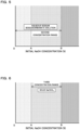
- the initial NaOH concentration is set within a first concentration range shown in FIG. 3 that is a range more than 0% and equal to or less than a NaOH concentration A required to produce NaHCO 3 with saturated solubility at the extraction temperature that is calculated based on the approximation equation of formula 3 above.
- the format of the correspondence between the temperature of the reaction liquid and the NaOH concentration required to produce NaHCO 3 with saturated solubility is not limited, and may be a higher-order approximation equation instead of the first-order approximation equation in the first embodiment, or may be determined by a map or a logical formula.
- the maximum temperature of the reaction liquid after the production of NaHCO 3 in the reaction liquid is set to less than 65°C. Since the above CO 2 immobilization reaction is an exothermic reaction, the temperature of the reaction liquid increases during CO 2 immobilization. However, the temperature (liquid temperature) of the reaction liquid is adjusted to less than 65°C by the above air pump 40 and the above liquid temperature adjustment device 50.
- the extraction temperature that is the liquid temperature when the target product is extracted from the reaction tank 11 can be set within a range of general outside air temperature. In the first embodiment, the extraction temperature is set to 0°C or more and 40°C or less.
- the upper limit A of the first concentration range shown in FIG. 3 can be set to 3.86 to 4.57% when the extraction temperature is 10°C or more and less than 20°C based on the values in the lower part of Table 1 above, and can preferably be set to 3.86%.
- the upper limit A of the first concentration range can be set to 4.57 to 5.29% when the extraction temperature is 20°C or more and less than 30°C, and can preferably be set to 4.57%.
- the upper limit A of the first concentration range can be set to 5.29 to 5.38% when the extraction temperature is 30°C or more and less than 40°C, and can preferably be set to 5.29%.
- the symbol B indicates a NaOH concentration required to produce Na 2 CO 3 with saturated solubility at the extraction temperature that is calculated based on an approximation equation of formula 4 described later.
- the suction operation of the air pump 40 is turned ON to start bubbling CO 2 -containing gas in the reaction tank 11, thereby bringing the CO 2 -containing gas into contact with the reaction liquid having the initial NaOH concentration. In this way, the CO 2 immobilization reaction is started.
- the pH sensor 13 detects that the pH of the reaction liquid in the reaction tank 11 has reached a value corresponding to the pH at which the total amount of NaOH has been converted to NaHCO 3 , the suction operation of the air pump 40 is turned OFF to stop bubbling the CO 2 -containing gas, thereby stopping the CO 2 immobilization reaction. Then, the target product is extracted from the reaction tank 11 via the drain cock 70 and collected in the collection container 75.
- the maximum temperature of the reaction liquid after the production of NaHCO 3 in the reaction liquid is set to less than 65°C, and the initial NaOH concentration is within the above first concentration range. Therefore, NaHCO 3 produced in the reaction tank 11 is not thermally decomposed and is not supersaturated. Thus, NaHCO 3 does not precipitate. As a result, a highly pure aqueous NaHCO 3 solution can be obtained as the target product, and the target product can selectively be produced easily. Since NaHCO 3 does not precipitate, clogging of the fine bubble forming device that is not shown and is provided at the tip of the pipe 41 can be prevented.
- the initial NaOH concentration is determined based on the approximation equation of formula 3 above.
- modification 1-1, 1-2, or 1-3 below can be adopted.
- the extraction temperature is set to 10°C or more and less than 20°C
- the initial concentration of NaOH is set within the first concentration range shown in FIG. 3 and is more than 0%
- the upper limit A can be set to 3.86 to 4.57%.
- the initial concentration of NaOH is preferably more than 0% and 3.86% or less.
- the extraction temperature is set to 20°C or more and less than 30°C
- the initial concentration of NaOH is set within the first concentration range shown in FIG. 3 and is more than 0%
- the upper limit A can be set to 4.57 to 5.29%.
- the initial concentration of NaOH is preferably more than 0% and 4.57% or less.
- the extraction temperature is set to 30°C or more and less than 40°C
- the initial concentration of NaOH is set within the first concentration range shown in FIG. 3 and is more than 0%
- the upper limit A can be set to 5.29 to 5.38%.
- the initial concentration of NaOH is preferably more than 0% and 5.29% or less.
- the configurations of the devices are similar to those in the first embodiment shown in FIG. 1 .
- the target product is the aqueous NaHCO 3 solution.
- the target product is an aqueous sodium sesquicarbonate solution in which NaHCO 3 and Na 2 CO 3 are dissolved in water.
- the initial concentration of NaOH is set to a value more than 0% and equal to or less than a NaOH concentration required to produce Na 2 CO 3 with saturated solubility at the extraction temperature that is derived based on the correspondence between the temperature of the reaction liquid and the NaOH concentration required to produce Na 2 CO 3 with saturated solubility.
- the saturated solubility of Na 2 CO 3 at 10°C intervals from 0°C to 40°C is first shown in an upper part of Table 2 below.
- the NaOH concentration required to produce Na 2 CO 3 with saturated solubility at each temperature is calculated as shown in a lower part of Table 2 below.
- a first-order approximation equation for the temperature (liquid temperature) and the NaOH concentration required to produce NaHCO 3 with saturated solubility shown in the lower part of Table 2 can be calculated as shown in formula 4 below, and can be shown as in FIG. 4 .
- y 1.112 x + 3.70
- R 2 0.966 (where y is the NaOH concentration required to produce Na 2 CO 3 with saturated solubility, and x is the liquid temperature)
- the format of the correspondence between the temperature of the reaction liquid and the NaOH concentration required to produce Na 2 CO 3 with saturated solubility is not limited, and may be a higher-order approximation equation instead of the first-order approximation equation in the first embodiment, or may be determined by a map or a logical formula.
- the maximum temperature of the reaction liquid after the production of NaHCO 3 in the reaction liquid is set to less than 65°C as in the first embodiment.
- the extraction temperature that is the liquid temperature when the target product is extracted from the reaction tank 11 is also set to 0°C or more and 40°C or less as in the first embodiment.
- the other configurations are similar to those in the first embodiment.
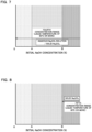
- the upper limit B of the second concentration range shown in FIG. 5 can be set to 9.43 to 16.22% when the extraction temperature is 10°C or more and less than 20°C based on the values in the lower part of Table 2 above, and can preferably be set to 9.43%.
- the upper limit B of the second concentration range can be set to 16.22 to 29.96% when the extraction temperature is 20°C or more and less than 30°C, and can preferably be set to 16.22%.
- the upper limit B of the second concentration range can be set to 29.96 to 36.98% when the extraction temperature is 30°C or more and less than 40°C, and can preferably be set to 29.96%.
- the symbol A indicates the NaOH concentration required to produce NaHCO 3 with saturated solubility at the extraction temperature that is calculated based on the approximation equation of formula 3 described above.
- the suction operation of the air pump 40 is turned ON to start bubbling CO 2 -containing gas in the reaction tank 11, thereby bringing the CO 2 -containing gas into contact with the reaction liquid having the initial NaOH concentration. In this way, the CO 2 immobilization reaction is started.
- the pH sensor 13 detects that the pH of the reaction liquid in the reaction tank 11 has reached a value corresponding to the pH at which the total amount of NaOH has been consumed and the ratio of Na 2 CO 3 to NaHCO 3 is 50:50 as desired, the suction operation of the air pump 40 is turned OFF to stop bubbling the CO 2 -containing gas, thereby stopping the CO 2 immobilization reaction.
- the maximum temperature of the reaction liquid after the production of NaHCO 3 in the reaction liquid is set to less than 65°C. Therefore, NaHCO 3 produced in the reaction tank 11 is not thermally decomposed. Since the initial NaOH concentration is within the above second concentration range, Na 2 CO 3 is not supersaturated and does not precipitate. As a result, a highly pure aqueous sodium sesquicarbonate solution in which NaHCO 3 and Na 2 CO 3 are dissolved in water can be obtained as the target product, and the target product can selectively be produced easily. Since Na 2 CO 3 does not precipitate, the reactivity of the reaction between Na 2 CO 3 and CO 2 for producing NaHCO 3 shown in formula 2 above is prevented from decreasing, and the CO 2 collection rate is improved.
- the initial NaOH concentration is determined based on the approximation equation of formula 4 above.
- modification 2-1, 2-2, or 2-3 below can be adopted.
- the extraction temperature is set to 10°C or more and less than 20°C
- the initial concentration of NaOH is set within the second concentration range shown in FIG. 5 and is more than 0%
- the upper limit B can be set to 9.43 to 16.22%.
- the initial concentration of NaOH is preferably more than 0% and 9.43% or less.
- the extraction temperature is set to 20°C or more and less than 30°C
- the initial concentration of NaOH is set within the second concentration range shown in FIG. 5 and is more than 0%
- the upper limit B can be set to 16.22 to 29.96%.
- the initial concentration of NaOH is preferably more than 0% and 16.22% or less.
- the extraction temperature is set to 30°C or more and less than 40°C
- the initial concentration of NaOH is set within the second concentration range shown in FIG. 5 and is more than 0%
- the upper limit B can be set to 29.96 to 36.98%.
- the initial concentration of NaOH is preferably more than 0% and 29.96% or less.
- the configurations of the devices are similar to those in the first embodiment shown in FIG. 1 .
- the target product is solid NaHCO 3 .
- the initial concentration of NaOH is set to be equal to or more than the NaOH concentration required to produce NaHCO 3 with saturated solubility at the extraction temperature that is derived based on the correspondence between the temperature of the reaction liquid and the NaOH concentration required to produce NaHCO 3 with saturated solubility, and to be equal to or less than the NaOH concentration required to produce Na 2 CO 3 with saturated solubility at the extraction temperature that is derived based on the correspondence between the temperature of the reaction liquid and the NaOH concentration required to produce Na 2 CO 3 with saturated solubility.
- the "NaOH concentration required to produce NaHCO 3 with saturated solubility at the extraction temperature that is derived based on the correspondence between the temperature of the reaction liquid and the NaOH concentration required to produce NaHCO 3 with saturated solubility" is the NaOH concentration A calculated based on the approximation equation of formula 3 above in the first embodiment.
- the "NaOH concentration required to produce Na 2 CO 3 with saturated solubility at the extraction temperature that is derived based on the correspondence between the temperature of the reaction liquid and the NaOH concentration required to produce Na 2 CO 3 with saturated solubility" is the NaOH concentration B calculated based on the approximation equation of formula 4 above in the second embodiment.
- the initial NaOH concentration is set to a third concentration range shown in FIG. 6 that is a range equal to or more than the NaOH concentration A required to produce NaHCO 3 with saturated solubility at the extraction temperature that is calculated based on the approximation equation of formula 3 above and equal to or less than the NaOH concentration B required to produce Na 2 CO 3 with saturated solubility at the extraction temperature that is calculated based on the approximation equation of formula 4 above.
- the maximum temperature of the reaction liquid after the production of NaHCO 3 in the reaction liquid is set to less than 65°C as in the first embodiment.
- the extraction temperature that is the liquid temperature when the target product is extracted from the reaction tank 11 is also set to 0°C or more and 40°C or less as in the first embodiment.
- the other configurations are similar to those in the first embodiment.
- the lower limit A of the third concentration range shown in FIG. 6 can be set to 3.86 to 4.57% when the extraction temperature is 10°C or more and less than 20°C based on the values in the lower part of Table 1 above, and can preferably be set to 3.86%.
- the upper limit B can be set to 9.43 to 16.22% based on the values in the lower part of Table 2 above, and can preferably be set to 9.43%.
- the lower limit A of the third concentration range can be set to 4.57 to 5.29% when the extraction temperature is 20°C or more and less than 30°C based on the values in the lower part of Table 1 above, and can preferably be set to 4.57%.
- the upper limit B can be set to 16.22 to 29.96% based on the values in the lower part of Table 2 above, and can preferably be set to 16.22%.
- the lower limit A of the third concentration range can be set to 5.29 to 5.38% when the extraction temperature is 30°C or more and less than 40°C based on the values in the lower part of Table 1 above, and can preferably be set to 5.29%.
- the upper limit B can be set to 29.96 to 36.98% based on the values in the lower part of Table 2 above, and can preferably be set to 29.96%.
- the suction operation of the air pump 40 is turned ON to start bubbling CO 2 -containing gas in the reaction tank 11, thereby bringing the CO 2 -containing gas into contact with the reaction liquid having the initial NaOH concentration. In this way, the CO 2 immobilization reaction is started.
- the pH sensor 13 detects that the pH of the reaction liquid in the reaction tank 11 has reached a value corresponding to the pH at which the total amount of NaOH has been consumed and the ratio of Na 2 CO 3 to NaHCO 3 is 50:50
- the suction operation of the air pump 40 is turned OFF to stop bubbling the CO 2 -containing gas, thereby stopping the CO 2 immobilization reaction.
- the initial NaOH concentration is determined based on the approximation equations of formulas 3 and 4 above.
- modification 3-1, 3-2, or 3-3 below can be adopted.
- the extraction temperature is set to 10°C or more and less than 20°C
- the initial concentration of NaOH is set within the third concentration range shown in FIG. 6
- the lower limit A can be set to 3.86 to 4.57%
- the upper limit B can be set to 9.43 to 16.22%.
- the initial concentration of NaOH can be set to 3.86% or more and 9.43% or less.
- the extraction temperature is set to 20°C or more and less than 30°C
- the initial concentration of NaOH is set within the third concentration range shown in FIG. 6
- the lower limit A can be set to 4.57 to 5.29%
- the upper limit B can be set to 16.22 to 29.96%.
- the initial concentration of NaOH can be set to 4.57% or more and 16.22% or less.
- the extraction temperature is set to 30°C or more and less than 40°C
- the initial concentration of NaOH is set within the third concentration range shown in FIG. 6
- the lower limit A can be set to 5.29 to 5.38%
- the upper limit B can be set to 29.96 to 36.98%.
- the initial concentration of NaOH can be set to 5.29% or more and 29.96% or less.
- the configurations of the devices are similar to those in the first embodiment shown in FIG. 1 .
- the target product is an aqueous Na 2 CO 3 solution or solid Na 2 CO 3 .
- the initial concentration of NaOH is a value more than 0% and is within a fourth concentration range shown in FIG. 7 .
- the maximum temperature of the reaction liquid after the production of NaHCO 3 in the reaction liquid is set to 65°C or more. Since the above CO 2 immobilization reaction is an exothermic reaction, the temperature of the reaction liquid increases during CO 2 immobilization.
- the temperature (liquid temperature) of the reaction liquid is less than 65°C, heating is performed to a temperature of 65°C or more by the above air pump 40 and the above liquid temperature adjustment device 50.
- the extraction temperature that is the liquid temperature when the target product is extracted from the reaction tank 11 is set to 0°C or more and 40°C or less as in the first embodiment.
- the other configurations are similar to those in the first embodiment.
- the suction operation of the air pump 40 is turned ON to start bubbling CO 2 -containing gas in the reaction tank 11, thereby bringing the CO 2 -containing gas into contact with the reaction liquid having the initial NaOH concentration. In this way, the CO 2 immobilization reaction is started.
- the pH sensor 13 detects the pH of the reaction liquid in the reaction tank 11 indicating that the total amount of NaOH has been consumed, the suction operation of the air pump 40 is turned OFF to stop bubbling the CO 2 -containing gas, thereby stopping the CO 2 immobilization reaction.
- the maximum temperature of the reaction liquid after the production of NaHCO 3 in the reaction liquid is set to 65°C or more. Therefore, NaHCO 3 produced in the reaction tank 11 is thermally decomposed. Therefore, when the initial NaOH concentration is within the above fourth concentration range, that is, the entire range, an aqueous Na 2 CO 3 solution or solid Na 2 CO 3 is present as a product but NaHCO 3 is not present in the reaction tank 11. As a result, highly pure Na 2 CO 3 can be obtained as the target product, and the target product can selectively be produced easily. Since NaHCO 3 is not present, clogging of the fine bubble forming device that is not shown and is provided at the tip of the pipe 41 due to the precipitation of NaHCO 3 can be prevented.
- the configurations of the devices are similar to those in the first embodiment shown in FIG. 1 .
- the target product is solid Na 2 CO 3 .
- the initial concentration of NaOH is set to be equal to or more than the NaOH concentration required to produce Na 2 CO 3 with saturated solubility at the extraction temperature that is derived based on the correspondence between the temperature of the reaction liquid and the NaOH concentration required to produce Na 2 CO 3 with saturated solubility.
- the "NaOH concentration required to produce Na 2 CO 3 with saturated solubility at the extraction temperature that is derived based on the correspondence between the temperature of the reaction liquid and the NaOH concentration required to produce Na 2 CO 3 with saturated solubility" is the NaOH concentration calculated based on the approximation equation of formula 4 above in the second embodiment.
- the initial NaOH concentration is set within a fifth concentration range shown in FIG. 8 that is a range equal to or more than the NaOH concentration required to produce Na 2 CO 3 with saturated solubility at the extraction temperature that is calculated based on the approximation equation of formula 4 above.
- the maximum temperature of the reaction liquid after the production of NaHCO 3 in the reaction liquid is set to 65°C or more as in the fourth embodiment.
- the extraction temperature that is the liquid temperature when the target product is extracted from the reaction tank 11 is also set to 0°C or more and 40°C or less as in the fourth embodiment.
- the other configurations are similar to those in the first embodiment.
- the lower limit B of the fifth concentration range shown in FIG. 8 can be set to 9.43 to 16.22% when the extraction temperature is 10°C or more and less than 20°C based on the values in the lower part of Table 2 above, and can preferably be set to 9.43%.
- the lower limit B of the fifth concentration range can be set to 16.22 to 29.96% when the extraction temperature is 20°C or more and less than 30°C based on the values in the lower part of Table 2 above, and can preferably be set to 16.22%.
- the lower limit B of the fifth concentration range can be set to 29.96 to 36.98% when the extraction temperature is 30°C or more and less than 40°C based on the values in the lower part of Table 2 above, and can preferably be set to 29.96%.
- the maximum temperature of the reaction liquid after the production of NaHCO 3 in the reaction liquid is set to 65°C or more. Therefore, NaHCO 3 produced in the reaction tank 11 is thermally decomposed. Since the initial NaOH concentration is set to the above fifth concentration range, Na 2 CO 3 is supersaturated and precipitates in the reaction tank 11. As a result, the only product that precipitates and becomes a solid in the reaction tank 11 is Na 2 CO 3 . Therefore, highly pure solid Na 2 CO 3 can be obtained as the target product by filtration or centrifugation of the collected matter in the collection container 75, and the target product can selectively be produced easily.
- the initial NaOH concentration is determined based on the approximation equation of formula 4 above.
- modification 5-1, 5-2, or 5-3 below can be adopted.
- the extraction temperature is set to 10°C or more and less than 20°C
- the initial concentration of NaOH is set within the fifth concentration range shown in FIG. 8
- the lower limit B can be set to 9.43 to 16.22%.
- the initial concentration of NaOH is preferably 9.43% or more.
- the extraction temperature is set to 20°C or more and less than 30°C
- the initial concentration of NaOH is set within the fifth concentration range shown in FIG. 8
- the lower limit B can be set to 16.22 to 29.96%.
- the initial concentration of NaOH is preferably 16.22% or more.
- the extraction temperature is set to 30°C or more and less than 40°C
- the initial concentration of NaOH is set within the fifth concentration range shown in FIG. 8
- the lower limit B can be set to 29.96 to 36.98%.
- the initial concentration of NaOH is preferably 29.96% or more.
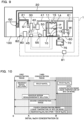
- the CO 2 collection system 1 of the sixth embodiment includes an adjustment unit 80 and an initial NaOH concentration setting unit 81.
- the other configurations in the sixth embodiment are the same as those in the first embodiment shown in FIG. 1 , and therefore the same reference numerals as in the first embodiment are used and the description thereof is omitted.
- the adjustment unit 80 shown in FIG. 9 adjusts the maximum temperature of the reaction liquid after the production of NaHCO 3 in the reaction liquid, the extraction temperature, and the initial concentration of NaOH in the reaction liquid to adjust the target product.
- the adjustment unit 80 adjusts the temperature (liquid temperature) of the reaction liquid by adjusting the flow rate of the air pump 40 through the pump control 45 and by controlling the drive of the liquid temperature adjustment device 50 through the liquid temperature adjustment device control unit 55. Further, the initial NaOH concentration of the reaction liquid to be introduced into the reaction tank 11 is adjusted via the initial NaOH concentration setting unit 81 described later.
- the initial NaOH concentration setting unit 81 shown in FIG. 9 is configured to introduce the reaction liquid having the initial NaOH concentration adjusted by the adjustment unit 80 into the reaction tank 11 from a reaction liquid introduction unit 15 provided in the reaction tank 11.
- the adjustment unit 80 includes a selection unit 82 for a user to select a desired target product, and the product selected by the user via the selection unit 82 is set as the target product. Then, the initial NaOH concentration of the reaction liquid and the temperature (liquid temperature) of the reaction liquid are adjusted according to the set target product.
- the correspondence between the initial NaOH concentration and the target product can be shown as in FIG. 10 .
- the initial NaOH concentration is adjusted within the first concentration range via the initial NaOH concentration setting unit 81 as in the first embodiment, and the maximum temperature of the reaction liquid and the extraction temperature are also adjusted via the air pump 40 and the liquid temperature adjustment device 50 as in the first embodiment.
- the aqueous NaHCO 3 solution can be obtained as the target product as in the first embodiment.
- the aqueous NaHCO 3 solution may be obtained as the target product as in modifications 1-1, 1-2, and 1-3.
- the initial NaOH concentration, the maximum temperature of the reaction liquid, and the extraction temperature are adjusted via the initial NaOH concentration setting unit 81, the air pump 40, and the liquid temperature adjustment device 50 as in the second embodiment.
- the aqueous sodium sesquicarbonate solution can be obtained as the target product as in the second embodiment.
- the initial NaOH concentration, the maximum temperature of the reaction liquid, and the extraction temperature are adjusted via the initial NaOH concentration setting unit 81, the air pump 40, and the liquid temperature adjustment device 50 as in the third embodiment.
- solid NaHCO 3 can be obtained as the target product as in the third embodiment.
- the initial NaOH concentration, the maximum temperature of the reaction liquid, and the extraction temperature are adjusted via the initial NaOH concentration setting unit 81, the air pump 40, and the liquid temperature adjustment device 50 as in the fourth embodiment.
- the aqueous Na 2 CO 3 solution or solid Na 2 CO 3 can be obtained as the target product as in the fourth embodiment.
- the initial NaOH concentration, the maximum temperature of the reaction liquid, and the extraction temperature are adjusted via the initial NaOH concentration setting unit 81, the air pump 40, and the liquid temperature adjustment device 50 as in the fifth embodiment.
- solid Na 2 CO 3 can be obtained as the target product as in the third embodiment.
- the target product to be extracted from the reaction liquid is adjusted by adjusting the maximum temperature of the reaction liquid after the production of NaHCO 3 in the reaction liquid, the extraction temperature that is the temperature of the reaction liquid when the target product is extracted from the reaction tank, and the initial concentration of NaOH in the reaction liquid.
- the product can selectively be produced easily, and the desired target product can be extracted with high purity.
Landscapes
- Chemical & Material Sciences (AREA)
- Engineering & Computer Science (AREA)
- General Chemical & Material Sciences (AREA)
- Environmental & Geological Engineering (AREA)
- Analytical Chemistry (AREA)
- Oil, Petroleum & Natural Gas (AREA)
- Chemical Kinetics & Catalysis (AREA)
- Organic Chemistry (AREA)
- Biomedical Technology (AREA)
- Health & Medical Sciences (AREA)
- Materials Engineering (AREA)
- Inorganic Chemistry (AREA)
- Gas Separation By Absorption (AREA)
- Treating Waste Gases (AREA)
Applications Claiming Priority (1)
| Application Number | Priority Date | Filing Date | Title |
|---|---|---|---|
| PCT/JP2022/032631 WO2024047761A1 (ja) | 2022-08-30 | 2022-08-30 | Co2回収システム |
Publications (2)
| Publication Number | Publication Date |
|---|---|
| EP4582384A1 true EP4582384A1 (de) | 2025-07-09 |
| EP4582384A4 EP4582384A4 (de) | 2025-10-29 |
Family
ID=90098895
Family Applications (1)
| Application Number | Title | Priority Date | Filing Date |
|---|---|---|---|
| EP22956691.4A Pending EP4582384A4 (de) | 2022-08-30 | 2022-08-30 | Co2-rückgewinnungssystem |
Country Status (4)
| Country | Link |
|---|---|
| EP (1) | EP4582384A4 (de) |
| JP (1) | JPWO2024047761A1 (de) |
| CN (1) | CN119744193A (de) |
| WO (1) | WO2024047761A1 (de) |
Family Cites Families (10)
| Publication number | Priority date | Publication date | Assignee | Title |
|---|---|---|---|---|
| JPS4816799B1 (de) * | 1969-06-06 | 1973-05-24 | ||
| AR208406A1 (es) * | 1974-05-22 | 1976-12-27 | Rhone Poulenc Ind | Procedimiento y aparato para obtener bicarbonato de sodio |
| JPS5560021A (en) * | 1978-10-27 | 1980-05-06 | Toyo Soda Mfg Co Ltd | Production of sodium bicarbonate |
| JPS5717424A (en) * | 1980-07-08 | 1982-01-29 | Toyo Soda Mfg Co Ltd | Carbonating apparatus |
| JPS5792517A (en) * | 1980-11-27 | 1982-06-09 | Toyo Soda Mfg Co Ltd | Preparation of sodium carbonate monohydrate |
| JP3070750B2 (ja) * | 1990-03-23 | 2000-07-31 | 旭硝子株式会社 | 重曹の製造方法 |
| JP3114775B2 (ja) * | 1993-03-13 | 2000-12-04 | 戸田工業株式会社 | 炭酸ナトリウム水溶液の製造法 |
| WO2008018928A2 (en) | 2006-04-27 | 2008-02-14 | President And Fellows Of Harvard College | Carbon dioxide capture and related processes |
| JP5196482B2 (ja) * | 2007-09-28 | 2013-05-15 | 一般財団法人電力中央研究所 | 炭酸アルカリ併産タービン設備 |
| JP2012206872A (ja) * | 2011-03-29 | 2012-10-25 | Lion Corp | 炭酸水素ナトリウムの製造方法および製造システム |
-
2022
- 2022-08-30 WO PCT/JP2022/032631 patent/WO2024047761A1/ja not_active Ceased
- 2022-08-30 JP JP2024543663A patent/JPWO2024047761A1/ja active Pending
- 2022-08-30 CN CN202280099331.8A patent/CN119744193A/zh active Pending
- 2022-08-30 EP EP22956691.4A patent/EP4582384A4/de active Pending
Also Published As
| Publication number | Publication date |
|---|---|
| WO2024047761A1 (ja) | 2024-03-07 |
| CN119744193A (zh) | 2025-04-01 |
| EP4582384A4 (de) | 2025-10-29 |
| JPWO2024047761A1 (de) | 2024-03-07 |
Similar Documents
| Publication | Publication Date | Title |
|---|---|---|
| CA2658778C (en) | Retention of noble gases in the exhaled air of ventilated patients by membrane separation | |
| RU2488431C2 (ru) | Способ очистки отходящих газов | |
| JP6262978B2 (ja) | 硫黄酸化物を含むガスの脱硫方法及び脱硫装置 | |
| EP2668993A1 (de) | Kohlendioxidabscheidungssystem und Betriebsverfahren dafür | |
| US9327241B2 (en) | Method and device for treating a contaminated alkaline amino acid saline solution | |
| US10213728B2 (en) | Method for separating carbon dioxide from a gas flow, in particular from a flue gas flow, and separating device for separating carbon dioxide from a gas flow, in particular from a flue gas flow | |
| EP3406318A1 (de) | Kohlendioxidtrenn-/rückgewinnungsvorrichtung, verbrennungssystem damit, thermisches stromerzeugungssystem damit und verfahren zur abscheidung und rückgewinnung von kohlendioxid | |
| EP4582384A1 (de) | Co2-rückgewinnungssystem | |
| KR101590728B1 (ko) | 유해물질 제거 장치 및 방법 | |
| CN109153001A (zh) | 吸附剂、二氧化碳的除去方法、二氧化碳除去器、以及空调装置 | |
| JPH0523535A (ja) | 燃焼排ガスから酸性ガスの除去方法 | |
| CN108624370A (zh) | 沼气膜分离提纯制生物甲烷的方法 | |
| CN109414677A (zh) | 吸附剂及其制造方法、二氧化碳的除去方法、二氧化碳除去器、以及空调装置 | |
| JP3929723B2 (ja) | メタン濃縮装置 | |
| JP2013208533A (ja) | 二酸化炭素回収システム | |
| JPH11243985A (ja) | L−グルタミン酸発酵における二酸化炭素の回収法 | |
| JPH0736886B2 (ja) | ガス回収循環装置 | |
| JP2000140576A (ja) | フッ素系ガス含有混合物の無害化処理システム | |
| JP2010207726A (ja) | ガス精製装置及びガス精製方法 | |
| JP2003205219A (ja) | 排ガスの処理方法及び処理装置 | |
| JP2010207727A (ja) | ガス精製装置及びガス精製方法 | |
| EP4552728A1 (de) | Verfahren und vorrichtung zur sorption/desorption von kohlendioxid | |
| JPH1157395A (ja) | 排煙処理方法及び排煙処理装置 | |
| CN217887509U (zh) | 二氧化碳回收活化利用装置 | |
| CN215610345U (zh) | 一种贵金属酸性废液浓缩废气治理装置 |
Legal Events
| Date | Code | Title | Description |
|---|---|---|---|
| STAA | Information on the status of an ep patent application or granted ep patent |
Free format text: STATUS: THE INTERNATIONAL PUBLICATION HAS BEEN MADE |
|
| PUAI | Public reference made under article 153(3) epc to a published international application that has entered the european phase |
Free format text: ORIGINAL CODE: 0009012 |
|
| STAA | Information on the status of an ep patent application or granted ep patent |
Free format text: STATUS: REQUEST FOR EXAMINATION WAS MADE |
|
| 17P | Request for examination filed |
Effective date: 20250219 |
|
| AK | Designated contracting states |
Kind code of ref document: A1 Designated state(s): AL AT BE BG CH CY CZ DE DK EE ES FI FR GB GR HR HU IE IS IT LI LT LU LV MC MK MT NL NO PL PT RO RS SE SI SK SM TR |
|
| A4 | Supplementary search report drawn up and despatched |
Effective date: 20251001 |
|
| RIC1 | Information provided on ipc code assigned before grant |
Ipc: C01D 7/07 20060101AFI20250925BHEP Ipc: C01D 7/14 20060101ALI20250925BHEP Ipc: B01D 53/14 20060101ALI20250925BHEP Ipc: B01D 53/62 20060101ALI20250925BHEP Ipc: B01D 53/34 20060101ALI20250925BHEP |
|
| DAV | Request for validation of the european patent (deleted) | ||
| DAX | Request for extension of the european patent (deleted) |