EP4582222A1 - Working machine - Google Patents
Working machine Download PDFInfo
- Publication number
- EP4582222A1 EP4582222A1 EP23859927.8A EP23859927A EP4582222A1 EP 4582222 A1 EP4582222 A1 EP 4582222A1 EP 23859927 A EP23859927 A EP 23859927A EP 4582222 A1 EP4582222 A1 EP 4582222A1
- Authority
- EP
- European Patent Office
- Prior art keywords
- unit
- magazine
- working machine
- axis
- motor
- Prior art date
- Legal status (The legal status is an assumption and is not a legal conclusion. Google has not performed a legal analysis and makes no representation as to the accuracy of the status listed.)
- Pending
Links
Images






Classifications
-
- B—PERFORMING OPERATIONS; TRANSPORTING
- B25—HAND TOOLS; PORTABLE POWER-DRIVEN TOOLS; MANIPULATORS
- B25C—HAND-HELD NAILING OR STAPLING TOOLS; MANUALLY OPERATED PORTABLE STAPLING TOOLS
- B25C1/00—Hand-held nailing tools; Nail feeding devices
- B25C1/06—Hand-held nailing tools; Nail feeding devices operated by electric power
-
- B—PERFORMING OPERATIONS; TRANSPORTING
- B25—HAND TOOLS; PORTABLE POWER-DRIVEN TOOLS; MANIPULATORS
- B25C—HAND-HELD NAILING OR STAPLING TOOLS; MANUALLY OPERATED PORTABLE STAPLING TOOLS
- B25C1/00—Hand-held nailing tools; Nail feeding devices
- B25C1/001—Nail feeding devices
-
- B—PERFORMING OPERATIONS; TRANSPORTING
- B25—HAND TOOLS; PORTABLE POWER-DRIVEN TOOLS; MANIPULATORS
- B25C—HAND-HELD NAILING OR STAPLING TOOLS; MANUALLY OPERATED PORTABLE STAPLING TOOLS
- B25C1/00—Hand-held nailing tools; Nail feeding devices
- B25C1/001—Nail feeding devices
- B25C1/003—Nail feeding devices for belts of nails
-
- B—PERFORMING OPERATIONS; TRANSPORTING
- B25—HAND TOOLS; PORTABLE POWER-DRIVEN TOOLS; MANIPULATORS
- B25C—HAND-HELD NAILING OR STAPLING TOOLS; MANUALLY OPERATED PORTABLE STAPLING TOOLS
- B25C1/00—Hand-held nailing tools; Nail feeding devices
- B25C1/04—Hand-held nailing tools; Nail feeding devices operated by fluid pressure, e.g. by air pressure
- B25C1/047—Mechanical details
Definitions
- the present invention relates to a working machine.
- Patent Document 1 International Publication No. WO2021/084993
- the size of the entire working machine tends to increase in order to avoid interference of the roll magazine with the motor housing.
- the increase in size of the working machine leads to degradation of operability and workability for the worker.
- the degradation of operability and workability leads to degradation of usability of the working machine. Therefore, there is a demand for a working machine with improved usability to be provided.
- a working machine includes: a magazine that houses a plurality of fasteners inside; an ejection unit to which the fastener is supplied; a striking unit that moves to one side in a first direction to strike the fastener supplied to the ejection unit; a biasing unit that biases the striking unit toward the one side in the first direction; a winding unit that winds up the striking unit toward the other side in the first direction against a biasing force of the biasing unit; and a motor that generates a driving force for driving the winding unit, and the magazine is provided at a position overlapping with the motor as viewed in a direction of a rotation axis of the motor.
- a working machine includes: a magazine that houses a plurality of fasteners inside; an ejection unit to which the fastener is supplied; a striking unit that moves to one side in a first direction to strike the fastener supplied to the ejection unit; a biasing unit that biases the striking unit toward the one side in the first direction; a winding unit that winds up the striking unit toward the other side in the first direction against a biasing force of the biasing unit by being rotated about a winding axis extending in a direction intersecting with the first direction; and a motor that generates a driving force for driving the winding unit, and the magazine is arranged on the winding axis.
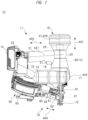
- the upper part of the drawing sheet in FIGS. 1 and 2 may be referred to as an upper side
- the lower part of the drawing sheet may be referred to as a lower side
- the right side of the drawing sheet may be referred to as a front side
- the left side of the drawing sheet may be referred to as a rear side
- the near side of the drawing sheet may be referred to as a right side
- the far side of the drawing sheet may be referred to as a left side
- the up-down direction may be referred to as a first direction AR1
- the lower side may be referred to as one side in the first direction AR1
- the upper side may be referred to as the other side in the first direction AR1.
- the cylinder case 20 supports a cylinder 28.
- the cylinder 28 is made of metal.
- the cylinder 28 is positioned with respect to the cylinder case 20 in a direction of a first center line X1 parallel to the first direction (up-down direction) AR1 and a radial direction (direction orthogonal to the first center line X1).
- an axis AX1 of the handle 21 extends along the second direction (front-rear direction) AR2 of the working machine 10. That is, the axis AX1 of the handle 21 is parallel to the second direction AR2. It can also be said that the axis AX1 of the handle 21 extends in a direction intersecting with the first direction (up-down direction) AR1.
- a trigger 51 is provided on the lower side of the handle 21. A worker, that is, a user can operate the trigger 51 while holding the handle 21.
- a trigger switch (not illustrated) is provided in the handle 21, and outputs an operation signal when an operation force is applied to the trigger 51. When the operation force to the trigger 51 is released, the trigger switch stops outputting the operation signal.
- the motor case 22 is a housing unit that houses the electric motor 15, the gear case 16, and the conversion mechanism 17 described below.
- the motor case 22 has a tubular shape extending along a rotation axis AX2 of the electric motor 15.
- the rotation axis AX2 of the electric motor 15 extends in a direction intersecting with the first direction (up-down direction) AR1.
- the motor case 22 that is, the electric motor 15
- the battery attachment unit 23 is arranged at the rear end (that is, the other side in the second direction AR2) of the handle 21 and the motor case 22.
- the power supply unit 14 described below is detachably attached to the battery attachment unit 23.
- a center axis AX3 of the battery attachment unit 23 is parallel to the axis AX1 of the handle 21, that is, the second direction AR2.
- the center axis AX3 of the battery attachment unit 23 is arranged at a position shifted to one side (right side) in the third direction (right-left direction) AR3 with respect to the handle 21. Therefore, the battery attachment unit 23 is connected to the handle 21 on the left side of the front end surface, and is connected to the motor case 22 on the right side of the front end surface.
- the protruding direction AR5 is a direction orthogonal to the rotation axis AX2 of the electric motor 15. As described above, since the rotation axis AX2 of the electric motor 15 is inclined with respect to the axis AX1 of the handle 21 as viewed in the first direction (as viewed in the up-down direction), the protruding direction AR5 intersects with the axis AX1 of the handle 21 at a non-right angle.
- the nose unit 13 is positioned and arranged in the direction of the first center line X1 and the radial direction of the cylinder 28 with respect to the cylinder case 20.
- the nose unit 13 includes a bumper support unit 31, an ejection unit 32, and a tubular unit 33.
- the bumper support unit 31 has a tubular shape and has a guide hole 34.
- the guide hole 34 is arranged to center on the first center line X1.
- the ejection unit 32 is connected to the bumper support unit 31 and the tubular unit 33, and protrudes to the lower side in the first direction AR1 from the bumper support unit 31.
- the ejection unit 32 has an ejection path 37, and the ejection path 37 is concentrically provided to center on the first center line X1.
- the driver blade 30 is movable along the first direction AR1 inside the ejection path 37.
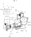
- a nail N (see FIG. 7 ), which is a fastener housed in the magazine 54 described below, is supplied to the ejection path 37 of the ejection unit 32.
- the electric motor 15 receives power supplied from the power supply unit 14 and rotates to drive the striking mechanism 12.
- the electric motor 15 is arranged in the motor case 22.
- the electric motor 15 is a brushless motor having a rotor and a stator. As illustrated in FIG. 1 , the rotation axis AX2, which is the rotation center of the electric motor 15, is orthogonal to the first center line X1 as viewed in the right-left direction (third direction AR3).
- the driver blade 30 descends due to the pressure in the pressure chamber 27 described below, and strikes the nail N supplied to the ejection unit 32. That is, the piston 29 and the driver blade 30 function as striking units that move to one side (lower side) in the first direction AR1 to strike the nail N which is a fastener supplied to the ejection unit 32. As a result, the nail N is struck by the driver blade 30 and driven into the workpiece (driven material).
- the supply mechanism 19 supplies the nail N housed in the magazine 54 described below into the ejection unit 32 along a fourth direction AR4.
- the fourth direction AR4 is a direction that intersects with the first direction AR1 and is not parallel to the rotation axis AX2 (that is, the second direction AR2) of the electric motor 15.
- the supply mechanism 19 includes a spring 59, a solenoid 60, an iron core 61, and a feeder unit 62.
- the feeder unit 62 can reciprocate along the fourth direction AR4 together with the iron core 61.
- the feeder unit 62 is provided with a plurality of feeding claws (not illustrated) at predetermined intervals along the fourth direction AR4.
- the solenoid 60 includes a bobbin, a coil provided in the bobbin, and the like.
- the iron core 61 can reciprocate along the fourth direction AR4 with respect to the bobbin of the solenoid 60.
- the iron core 61 is made of, for example, a magnetic material such as iron.
- the spring 59 is a biasing member that biases the iron core 61 toward the front side in the fourth direction AR4, and positions the feeder unit 62 at an initial position.
- the coil of the solenoid 60 is connected to the power supply unit 14, and generates a magnetic attraction force when current is supplied by the power supply unit 14. Due to this magnetic attraction force, the iron core 61 moves to the rear side in the fourth direction AR4 against the biasing force of the spring 59.
- the feeder unit 62 also moves to a predetermined position (nail attachment position) on the rear side in the fourth direction AR4.
- the feeding claw provided in the feeder unit 62 does not enter a space between the plurality of nails N connected by a connecting element described below. Therefore, the plurality of nails N are not moved to the front side in the fourth direction AR4.
- the feeding claw provided in the feeder unit 62 enters the space between the nails N connected by the connecting element.
- the coil eliminates the magnetic attraction force.
- the iron core 61 moves to the front side in the fourth direction AR4 due to the biasing force of the spring 59.
- the feeder unit 62 also moves from the nail attachment position to the front side in the fourth direction AR4 and moves to the initial position.
- the nail N is supplied to the ejection unit 32 on the front side in the fourth direction AR4 by the feeding claw that moves together with the feeder unit 62.
- the feeder unit 62 positions the nail N, which is located at the head of the connecting element among the nails N housed in the magazine 54, to the lower side of the driver blade 30.
- the magazine 54 has a drum unit 63 and a magazine cover 64, and houses therein the nails N, which are a plurality of fasteners connected to each other, in a roll shape.
- the plurality of nails N are connected to each other by the connecting element such as an adhesive and a wire, and each nail N extends to be parallel to the axis AX5.
- the plurality of connected nails N are arranged in the drum unit 63 in a spiral state, that is, in a rolled state, of being wound around the axis AX5.
- the drum unit 63 is hollow and has a circular plate-shaped bottom surface 63a formed on the lower side and a side surface 63b erecting upward from the right side edge of the bottom surface 63a. In other words, an opening provided with no drum unit 63 is formed on the upper side and the left side of the magazine 54. Through this opening, the plurality of connected nails N are supplied to the inside of the drum unit 63. The plurality of supplied nails N are supported by the bottom surface 63a and the side surface 63b and housed in the drum unit 63. That is, the drum unit 63 functions as a housing unit that houses a plurality of fasteners.
- the front end of the side surface 63b of the drum unit 63 is connected to the supply mechanism 19 and fixed to the housing 11.
- the rear end of the side surface 63b of the drum unit 63 is coupled with the magazine cover 64 described below.
- a rotation axis AX6 of the coupling mechanism 65 is in a direction parallel to the axis AX5 of the magazine 54.
- This coupling mechanism 65 causes the magazine cover 64 to be rotated (that is, opened and closed) with respect to the drum unit 63 fixed to the housing 11 around the rotation axis AX6.
- FIGS. 5 and 7 each illustrate a state in which the magazine cover 64 is open. In this state, a plurality of fasteners are supplied in the drum unit 63 as described above. When the magazine cover 64 is in the open state, as illustrated in FIGS. 5 and 7 , the magazine cover 64 is located on the rear side and the upper side of the drum unit 63 of the magazine 54.
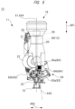
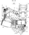
- the magazine 54 is provided at a position overlapping with the electric motor 15 as viewed in the direction of the rotation axis AX2 of the electric motor 15.
- the drum unit 63 of the magazine 54 is provided at a position overlapping with the electric motor 15 as viewed in the direction of the rotation axis AX2 of the electric motor 15 (overlapping portion G1 in FIG. 8 ). That is, the drum unit 63 of the magazine 54 in the front-rear direction (second direction AR2) illustrated in FIG. 1 is arranged further on the rear side than the electric motor 15, and the drum unit 63 of the magazine 54 in the right-left direction (third direction AR3) illustrated in FIG.
- the drum unit 63 of the magazine 54 is arranged at a position overlapping with the electric motor 15 as viewed in the direction of the rotation axis AX2 of the electric motor 15. That is, the drum unit 63 of the magazine 54 is shifted to the rear side and the left side of the electric motor 15 to such an extent that the drum unit 63 is arranged at a position overlapping with the electric motor 15 as viewed in the direction of the rotation axis AX2 of the electric motor 15.
- FIGS. 1 , 2 , 3 , and 9 illustrate a state in which the magazine cover 64 is closed. By closing the magazine cover 64, it is possible to prevent the plurality of fasteners housed in the drum unit 63 from falling off to the outside.
- the motor case 22 has a tubular shape, and a recess 22a is provided in a part of the motor case 22 as illustrated in FIGS. 7 and 9 .
- the recess 22a is formed on the lower rear side of the motor case 22, that is, at a position facing the upper surface 64a of the magazine cover 64 when the magazine cover 64 is in a closed state.
- the upper surface 64a of the magazine cover 64 is formed to have an arc shape around the axis AX5 of the magazine 54 so as to protrude toward the motor case 22, and a wall surface 22b of the recess 22a is formed to have an arc shape so as to be recessed in a direction away from the magazine cover 64.
- An outside diameter D1 of the motor case 22 in the region where the recess 22a is formed is smaller than an outside diameter D2 in the other region of the motor case 22 (see FIG. 9 ). Therefore, a problem that the magazine cover 64 cannot be closed due to interference between the magazine cover 64 and the motor case 22 is prevented from occurring. That is, the motor case 22 is provided with the recess 22a for avoiding the interference with the magazine cover 64.
- the recess 22a enables the motor case 22 and the magazine cover 64 to be arranged close to each other, and a virtual circle 22c coaxial with the motor case 22 and having a diameter equal to the outside diameter D2 comes into contact with the magazine cover 64.
- the center axis AX3 of the battery attachment unit 23 is not limited to the one that is parallel to the axis AX1 of the handle 21, that is, the second direction AR2.
- the center axis AX3 of the battery attachment unit 23 may be parallel to the rotation axis AX2 of the electric motor 15, that is, non-parallel to the second direction AR2.
- the lengths of the battery attachment unit 23 and the power supply unit 14 attached to the battery attachment unit 23 along the second direction AR2 are shorter than those when the center axis AX3 of the battery attachment unit 23 is parallel to the second direction AR2. That is, the entire length of the working machine 10 along the second direction AR2 can be shortened.
- the working machine 10 includes a housing 11, a striking mechanism 12, a nose unit 13, a power supply unit 14, an electric motor 15, a gear case 16, a conversion mechanism 17, a pressure accumulation container 18, a supply mechanism 19, and a magazine 54.
- the magazine 54 includes a drum unit 63 having a substantially cylindrical shape.
- the conversion mechanism 17 illustrated in FIG. 10 is a winding unit that includes a pin wheel 46 illustrated in FIG. 12 and winds up a piston 29 and a driver blade 30 toward the other (upper) side in the up-down direction (first direction AR1) against the biasing force of a biasing unit (pressure chamber 27 illustrated in FIG. 17 ) by being rotated about a winding axis AX8 extending in a direction intersecting with the up-down direction (first direction AR1).
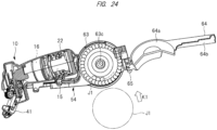
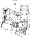
- the magazine 54 is provided at a position overlapping with the electric motor 15 as viewed in the direction of the rotation axis AX2 of the electric motor 15, that is, in the rear external view of the working machine 10.
- the substantially cylindrical drum unit 63 included in the magazine 54 of the working machine 10 of the second embodiment is provided at a position overlapping with the electric motor 15 in the rear external view of the working machine 10 in FIG. 14 .
- the distance of the magazine 54 from the electric motor 15 in the right-left direction can be minimized. This leads to a positional relationship in which the motor axis AX2 passes through the vicinity of the central portion of the drum unit 63 of the magazine 54 in the right-left direction (third direction AR3).
- the magazine 54 is arranged such that the motor axis AX2 passes through the vicinity of the center portion of the drum unit 63 of the magazine 54 in the up-down direction (first direction AR1), so that a distance L1 from the center of the pin wheel 46 (motor axis AX2) to the lower end (ejection port 32a) of the ejection unit 32 can be shortened as illustrated in FIG. 12 .
- the supply mechanism 19 including the magazine 54 illustrated in FIG. 10 is also arranged to be shifted to the upper side.
- the distance L1 from the center of the pin wheel 46 (motor axis AX2) to the lower end (ejection port 32a) of the ejection unit 32 can be shortened, and the height of the working machine 10 can be reduced.
- the coil eliminates the magnetic attraction force.
- the feeder unit 62 moves from the nail attachment position to the front side in the fourth direction AR4, and the nail N is supplied to the ejection unit 32 on the front side in the fourth direction AR4 by the movement of the feeder unit 62.
- the feeder unit 62 positions the nail N, which is located at the head of a connecting element among the nails N housed in the drum unit 63 of the magazine 54, to the lower side of the driver blade 30.
- the air Q1 is applied to the solenoid 60 provided in the solenoid cover 55, whereby the solenoid 60 can be cooled. Thereafter, the fed air Q1 is exhausted as exhaust air P2 from each air exhaust port 55a to the outside of the solenoid cover 55.
- a fan 56 is provided at a rotation shaft 15a of the electric motor 15.
- the fan 56 is rotated by the driving force of the electric motor 15.
- the fan 56 is, for example, a centrifugal fan, and the solenoid 60 and the feeder unit 62 are provided on air paths 57a and 57b of the fan 56.
- the solenoid 60 can be cooled by applying the air Q1 taken in by the rotation of the fan 56 to the solenoid 60. Further, by applying the air Q1 taken in by the rotation of the fan 56 to the solenoid 60 and the feeder unit 62, it is possible to reduce adhesion of dust generated at the time of nailing to the solenoid 60 and the feeder unit 62.
- the head of the worker may hit the wall or the like. Therefore, as in the working machine 10 of the second embodiment, reducing the height of the working machine 10 to reduce the size of the working machine 10 is effective in facilitating the nailing work of the worker.
Landscapes
- Engineering & Computer Science (AREA)
- Mechanical Engineering (AREA)
- Physics & Mathematics (AREA)
- Fluid Mechanics (AREA)
- Portable Nailing Machines And Staplers (AREA)
Applications Claiming Priority (2)
| Application Number | Priority Date | Filing Date | Title |
|---|---|---|---|
| JP2022137828 | 2022-08-31 | ||
| PCT/JP2023/027760 WO2024048158A1 (ja) | 2022-08-31 | 2023-07-28 | 作業機 |
Publications (1)
| Publication Number | Publication Date |
|---|---|
| EP4582222A1 true EP4582222A1 (en) | 2025-07-09 |
Family
ID=90099233
Family Applications (1)
| Application Number | Title | Priority Date | Filing Date |
|---|---|---|---|
| EP23859927.8A Pending EP4582222A1 (en) | 2022-08-31 | 2023-07-28 | Working machine |
Country Status (5)
| Country | Link |
|---|---|
| US (1) | US20260054361A1 (https=) |
| EP (1) | EP4582222A1 (https=) |
| JP (1) | JPWO2024048158A1 (https=) |
| CN (1) | CN119730992A (https=) |
| WO (1) | WO2024048158A1 (https=) |
Family Cites Families (7)
| Publication number | Priority date | Publication date | Assignee | Title |
|---|---|---|---|---|
| US7201303B2 (en) * | 2004-04-30 | 2007-04-10 | Senco Products, Inc. | Cordless fastener driving tool |
| WO2006124498A2 (en) * | 2005-05-12 | 2006-11-23 | Stanley Fastening Systems, L.P. | Fastener driving device |
| JP6100680B2 (ja) * | 2013-12-11 | 2017-03-22 | 株式会社マキタ | 打ち込み工具 |
| JP6586777B2 (ja) * | 2015-05-27 | 2019-10-09 | 工機ホールディングス株式会社 | 打込機 |
| US12186868B2 (en) | 2019-11-01 | 2025-01-07 | Koki Holdings Co., Ltd. | Driving device |
| US12103151B2 (en) * | 2019-11-28 | 2024-10-01 | Koki Holdings Co., Ltd. | Driving device |
| WO2023084622A1 (ja) * | 2021-11-10 | 2023-05-19 | 株式会社フリーク | 釘打ち機 |
-
2023
- 2023-07-28 JP JP2024544041A patent/JPWO2024048158A1/ja active Pending
- 2023-07-28 US US19/104,911 patent/US20260054361A1/en active Pending
- 2023-07-28 EP EP23859927.8A patent/EP4582222A1/en active Pending
- 2023-07-28 WO PCT/JP2023/027760 patent/WO2024048158A1/ja not_active Ceased
- 2023-07-28 CN CN202380060749.2A patent/CN119730992A/zh active Pending
Also Published As
| Publication number | Publication date |
|---|---|
| US20260054361A1 (en) | 2026-02-26 |
| CN119730992A (zh) | 2025-03-28 |
| JPWO2024048158A1 (https=) | 2024-03-07 |
| WO2024048158A1 (ja) | 2024-03-07 |
Similar Documents
| Publication | Publication Date | Title |
|---|---|---|
| US12594655B2 (en) | Driving tool with rotating member to move striking unit | |
| CN110573303B (zh) | 打入机 | |
| US12269150B2 (en) | Driving device | |
| JP6627990B2 (ja) | 打込機 | |
| EP2599591B1 (en) | Nail driving tool | |
| JP7420149B2 (ja) | 打込機 | |
| WO2019208104A1 (ja) | 打込機 | |
| US11654539B2 (en) | Driving tool | |
| TWI869395B (zh) | 釘打機 | |
| WO2019026502A1 (ja) | 打込機 | |
| TW202005755A (zh) | 釘打機 | |
| US20220134524A1 (en) | Driving tool | |
| EP4052850A1 (en) | Fastening tool | |
| EP4582222A1 (en) | Working machine | |
| JP2018167340A (ja) | 打込機 | |
| US12528167B2 (en) | Working machine | |
| JP6673524B2 (ja) | 打込機 | |
| US20260124726A1 (en) | Working machine | |
| JP2024108830A (ja) | 作業機及び作業機の製造方法 | |
| JP2024033908A (ja) | 作業機 | |
| US20250162118A1 (en) | Working machine | |
| JP2023163813A (ja) | 作業機 | |
| CN121398934A (zh) | 作业机 | |
| JP2024094762A (ja) | 作業機 | |
| JP2025006304A (ja) | 電動式打ち込み工具 |
Legal Events
| Date | Code | Title | Description |
|---|---|---|---|
| STAA | Information on the status of an ep patent application or granted ep patent |
Free format text: STATUS: THE INTERNATIONAL PUBLICATION HAS BEEN MADE |
|
| PUAI | Public reference made under article 153(3) epc to a published international application that has entered the european phase |
Free format text: ORIGINAL CODE: 0009012 |
|
| STAA | Information on the status of an ep patent application or granted ep patent |
Free format text: STATUS: REQUEST FOR EXAMINATION WAS MADE |
|
| 17P | Request for examination filed |
Effective date: 20250221 |
|
| AK | Designated contracting states |
Kind code of ref document: A1 Designated state(s): AL AT BE BG CH CY CZ DE DK EE ES FI FR GB GR HR HU IE IS IT LI LT LU LV MC ME MK MT NL NO PL PT RO RS SE SI SK SM TR |
|
| DAV | Request for validation of the european patent (deleted) | ||
| DAX | Request for extension of the european patent (deleted) |