EP4582010A2 - Dispositif médical rotatif - Google Patents
Dispositif médical rotatif Download PDFInfo
- Publication number
- EP4582010A2 EP4582010A2 EP25177519.3A EP25177519A EP4582010A2 EP 4582010 A2 EP4582010 A2 EP 4582010A2 EP 25177519 A EP25177519 A EP 25177519A EP 4582010 A2 EP4582010 A2 EP 4582010A2
- Authority
- EP
- European Patent Office
- Prior art keywords
- distal
- proximal
- channel
- handle
- washer
- Prior art date
- Legal status (The legal status is an assumption and is not a legal conclusion. Google has not performed a legal analysis and makes no representation as to the accuracy of the status listed.)
- Pending
Links
Images




Classifications
-
- A—HUMAN NECESSITIES
- A61—MEDICAL OR VETERINARY SCIENCE; HYGIENE
- A61B—DIAGNOSIS; SURGERY; IDENTIFICATION
- A61B1/00—Instruments for performing medical examinations of the interior of cavities or tubes of the body by visual or photographical inspection, e.g. endoscopes; Illuminating arrangements therefor
- A61B1/00002—Operational features of endoscopes
- A61B1/00039—Operational features of endoscopes provided with input arrangements for the user
- A61B1/00042—Operational features of endoscopes provided with input arrangements for the user for mechanical operation
-
- A—HUMAN NECESSITIES
- A61—MEDICAL OR VETERINARY SCIENCE; HYGIENE
- A61B—DIAGNOSIS; SURGERY; IDENTIFICATION
- A61B1/00—Instruments for performing medical examinations of the interior of cavities or tubes of the body by visual or photographical inspection, e.g. endoscopes; Illuminating arrangements therefor
- A61B1/00064—Constructional details of the endoscope body
- A61B1/00066—Proximal part of endoscope body, e.g. handles
-
- A—HUMAN NECESSITIES
- A61—MEDICAL OR VETERINARY SCIENCE; HYGIENE
- A61B—DIAGNOSIS; SURGERY; IDENTIFICATION
- A61B1/00—Instruments for performing medical examinations of the interior of cavities or tubes of the body by visual or photographical inspection, e.g. endoscopes; Illuminating arrangements therefor
- A61B1/005—Flexible endoscopes
- A61B1/0051—Flexible endoscopes with controlled bending of insertion part
-
- A—HUMAN NECESSITIES
- A61—MEDICAL OR VETERINARY SCIENCE; HYGIENE
- A61B—DIAGNOSIS; SURGERY; IDENTIFICATION
- A61B1/00—Instruments for performing medical examinations of the interior of cavities or tubes of the body by visual or photographical inspection, e.g. endoscopes; Illuminating arrangements therefor
- A61B1/005—Flexible endoscopes
- A61B1/0051—Flexible endoscopes with controlled bending of insertion part
- A61B1/0057—Constructional details of force transmission elements, e.g. control wires
-
- A—HUMAN NECESSITIES
- A61—MEDICAL OR VETERINARY SCIENCE; HYGIENE
- A61B—DIAGNOSIS; SURGERY; IDENTIFICATION
- A61B1/00—Instruments for performing medical examinations of the interior of cavities or tubes of the body by visual or photographical inspection, e.g. endoscopes; Illuminating arrangements therefor
- A61B1/012—Instruments for performing medical examinations of the interior of cavities or tubes of the body by visual or photographical inspection, e.g. endoscopes; Illuminating arrangements therefor characterised by internal passages or accessories therefor
-
- A—HUMAN NECESSITIES
- A61—MEDICAL OR VETERINARY SCIENCE; HYGIENE
- A61B—DIAGNOSIS; SURGERY; IDENTIFICATION
- A61B1/00—Instruments for performing medical examinations of the interior of cavities or tubes of the body by visual or photographical inspection, e.g. endoscopes; Illuminating arrangements therefor
- A61B1/012—Instruments for performing medical examinations of the interior of cavities or tubes of the body by visual or photographical inspection, e.g. endoscopes; Illuminating arrangements therefor characterised by internal passages or accessories therefor
- A61B1/018—Instruments for performing medical examinations of the interior of cavities or tubes of the body by visual or photographical inspection, e.g. endoscopes; Illuminating arrangements therefor characterised by internal passages or accessories therefor for receiving instruments
-
- A—HUMAN NECESSITIES
- A61—MEDICAL OR VETERINARY SCIENCE; HYGIENE
- A61B—DIAGNOSIS; SURGERY; IDENTIFICATION
- A61B1/00—Instruments for performing medical examinations of the interior of cavities or tubes of the body by visual or photographical inspection, e.g. endoscopes; Illuminating arrangements therefor
- A61B1/267—Instruments for performing medical examinations of the interior of cavities or tubes of the body by visual or photographical inspection, e.g. endoscopes; Illuminating arrangements therefor for the respiratory tract, e.g. laryngoscopes, bronchoscopes
- A61B1/2676—Bronchoscopes
-
- A—HUMAN NECESSITIES
- A61—MEDICAL OR VETERINARY SCIENCE; HYGIENE
- A61M—DEVICES FOR INTRODUCING MEDIA INTO, OR ONTO, THE BODY; DEVICES FOR TRANSDUCING BODY MEDIA OR FOR TAKING MEDIA FROM THE BODY; DEVICES FOR PRODUCING OR ENDING SLEEP OR STUPOR
- A61M25/00—Catheters; Hollow probes
- A61M25/01—Introducing, guiding, advancing, emplacing or holding catheters
- A61M25/0105—Steering means as part of the catheter or advancing means; Markers for positioning
- A61M25/0133—Tip steering devices
- A61M25/0136—Handles therefor
-
- A—HUMAN NECESSITIES
- A61—MEDICAL OR VETERINARY SCIENCE; HYGIENE
- A61M—DEVICES FOR INTRODUCING MEDIA INTO, OR ONTO, THE BODY; DEVICES FOR TRANSDUCING BODY MEDIA OR FOR TAKING MEDIA FROM THE BODY; DEVICES FOR PRODUCING OR ENDING SLEEP OR STUPOR
- A61M25/00—Catheters; Hollow probes
- A61M25/01—Introducing, guiding, advancing, emplacing or holding catheters
- A61M25/0105—Steering means as part of the catheter or advancing means; Markers for positioning
- A61M25/0133—Tip steering devices
- A61M25/0147—Tip steering devices with movable mechanical means, e.g. pull wires
Definitions
- This disclosure relates generally to a medical device including a shaft that is rotatable, relative to the handle. At least some embodiments of the disclosure relate to a medical device having a distal portion of a handle that is rotatable relative to a remaining portion of the handle, where the distal portion of the handle houses and is coupled to the shaft.
- bronchoscope or other scope or medical device
- other medical accessory devices In certain medical procedures, physicians and/or technicians need to control a bronchoscope (or other scope or medical device) and other medical accessory devices. Depending on a patient's position relative to that of the physician's, the physician controlling the device may need to contort and/or twist his/her body into exaggerated positions to navigate the medical device to the desired anatomical position. As a result, physicians may be placed in less than ideal ergonomic positions, and/or the procedure may suffer.
- a medical device may comprise a shaft, a handle including a proximal portion and a distal portion, wherein the distal portion is fixed to a proximal portion of the shaft, and a channel extending from the handle into the shaft, wherein the channel includes a proximal channel and a distal channel, the proximal channel being rotatable relative to the distal channel and aligned with the distal channel throughout rotation of the proximal channel, wherein the proximal portion includes the proximal channel and the distal portion includes the distal channel, wherein the distal portion is rotatable relative to the proximal portion of the handle, and the shaft is configured to rotate with the distal portion of the handle.
- the shaft may surround at least a portion of the distal channel, and the distal channel may be configured to rotate with the shaft and the distal portion of the handle.
- the distal portion of the handle may be rotatable relative to the proximal portion of the handle in either a clockwise direction or a counterclockwise direction.
- the rotation of the distal portion of the handle may be limited to a set degree of rotation.
- the distal portion of the handle may remain stationary relative to the proximal portion of the handle by frictional forces generated between a surface of the distal portion abutting a surface of the proximal portion.
- the handle may further include a guide, wherein the guide includes a lumen extending along a central axis of the guide, and wherein the lumen is positioned between the proximal channel and the distal channel, and the lumen is aligned with the proximal channel and the distal channel.
- the guide may be fixed to an inner surface of the proximal portion of the handle.
- the distal portion of the handle may further include a support along an inner surface of the distal portion of the handle, and the proximal portion of the shaft may be fixed to the support.
- a medical device may further comprise a lock having a first configuration and a second configuration, wherein, in the first configuration of the lock, the distal portion of the handle is stationary relative to the proximal portion of the handle, and, in the second configuration of the lock, the distal portion of the handle is rotatable relative to the proximal portion of the handle.
- the lock may include a first washer including a pin protruding proximally, wherein the distal channel extends through the first washer via an opening of the first washer, a second washer including a plurality of openings each configured to receive the pin, and a spring coupling a distal surface of the first washer to a base.
- the first washer may be spring-biased towards the second washer so that the pin of the first washer is engaged with one of the plurality of openings of the second washer, and wherein, the second configuration of the lock, the first washer may be spaced proximally from the second washer, compressing the spring, and so the pin is disengaged from all of the plurality of openings.
- the lock may further include a tube, wherein the tube extends through openings of the first washer and the second washer, wherein the tube sheaths over at least a portion of the distal channel, and wherein the first washer is configured to translate over the tube.
- the medical device may further comprise a first steering wire and a first gyro holding the first steering wire, wherein the first gyro includes a proximal gyro and a distal gyro, and wherein the distal gyro is interlocked with the proximal gyro so that the distal gyro is rotatable about the distal channel or the proximal channel, relative to the proximal gyro.
- the first steering wire may include a proximal wire and a distal wire, wherein a distal end of the proximal wire is coupled to a first enlargement, and a proximal end of the distal wire is coupled to a second enlargement, wherein the first enlargement is anchored to the proximal gyro and the second enlargement is anchored to the distal gyro.
- the distal wire may be pulled when the proximal wire is pulled via an actuation device.
- a medical device may comprise a shaft, a handle connected to a proximal portion of the shaft, and a channel extending from the handle into the shaft, wherein the channel is rotatable relative to the handle, and wherein a side wall of the channel includes an opening at a portion of the channel housed in the handle, wherein the handle defines a lumen in fluid communication with the opening of the channel, and wherein a proximal end of the lumen is configured for fluid communication with a suctioning source.
- the opening may be sealed from portions of the handle by a first seal and a second seal.
- the side wall of the channel may include a plurality of circumferentially distributed openings.
- a method of positioning a shaft of a medical device wherein the medical device further comprises a handle including a proximal portion and a distal portion rotatably attached to the proximal portion, and a channel extending from the second portion into a the shaft, wherein a proximal portion of the shaft is fixed to the distal portion of the handle, may comprise inserting a distal end of a shaft of the medical device into a body of a subject, and after the insertion step, rotating the distal portion of the handle, the shaft, and the channel relative to the proximal portion of the handle.
- the method may further comprise, after the insertion step, unlocking the distal portion of the handle from the proximal portion of the handle, rotating the distal portion of the handle, the shaft, and the channel relative to the proximal portion of the handle, and locking the distal portion of the handle to the proximal portion of the handle.
- distal refers to a portion farthest away from a user when introducing a device into a subject (e.g., a patient).
- proximal refers to a portion closest to the user when placing the device into the subject.
- Embodiments of the disclosure may solve one or more of the limitations in the art.
- the scope of the disclosure is defined by the attached claims and not the ability to solve a specific problem.
- the disclosure is drawn to medical devices including a shaft, which may be rotatable relative to a handle of the medical device.
- the medical devices can be, as examples, any scope (e.g., bronchoscope, duodenoscope, endoscope, colonoscope, ureteroscope, etc.), catheter, tool, instrument, or the like, having a shaft that extends distally from a handle.
- medical devices include a handle having a distal portion rotatable clockwise or counter-clockwise relative to a proximal portion of the handle.
- the medical devices further include a shaft fixedly coupled to and housed within the distal portion of the handle.
- a shaft fixedly coupled to and housed within the distal portion of the handle.
- the distal portion of a handle may be in one of two states or configurations. In a first state, the distal portion may remain stationary, relative to the proximal portion of the handle. In a second state, the distal portion of the handle may be rotating or capable of rotating, relative to the proximal portion of the handle. Alternatively, the proximal portion of the handle may be rotating or capable of rotating, relative to said distal portion.
- the shaft of the medical device rotates or remains stationary, in accordance with the distal portion of the handle.
- Embodiments of medical devices of the disclosure may employ any suitable means, e.g., friction, a locking/unlocking mechanism, etc., to place or maintain the distal portion of a handle in one of the two states described above.
- such medical devices may provide a user the option of rotating the distal portion of the handle (and thus, the shaft) in-procedure, via any suitable manner, e.g., by hand, mechanically, electrically, etc., and an option of maintaining the distal portion of the handle stationary in its current rotational position relative to a remainder of the device.
- a user of the device may comfortably access, view, and/or perform a therapeutic/diagnostic procedure at intended target sites, via rotation of the distal portion of the handle and the shaft, without having to twist and contort his/her wrists or other parts of the body, regardless of a patient's position relative to the user.
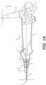
- Medical device 1 includes a flexible shaft 24 (e.g., a catheter) and a handle 5 connected to a proximal end of flexible shaft 24.
- Handle 5, or some other device for actuating or controlling medical device 1 and any tools or devices associated with medical device 1 includes an actuating device 43.
- Actuating device 43 controls articulation of flexible shaft 24, and/or an articulation joint at a distal end of flexible shaft 24, in multiple directions.
- Device 43 may be, for example, a rotatable knob that rotates about its axis to push/pull actuating elements, e.g., steering wires (not shown).
- actuating elements such as cables or wires suitable for medical procedures (e.g., medical grade plastic or metal), extend distally from a proximal end of medical device 1 and connect to a distal portion of flexible shaft 24 to control movement thereof.
- actuating elements independently of handle 5.
- Distal ends of actuating elements may extend through flexible shaft 24 and terminate at an articulation joint and/or a distal tip of flexible shaft 24.
- one or more actuating elements may be connected to an articulation joint, and actuation of actuating elements may control the articulation joint or the distal end of flexible shaft 24 to move in multiple directions (e.g. up/down and or left/right).
- one or more electrical cables may extend from the proximal end of medical device 1 to the distal end of flexible shaft 24 and may provide electrical controls to imaging, lighting, and/or other electrical devices at the distal end of flexible shaft 24, and may transmit imaging signals from the distal end of flexible shaft 24 proximally to be processed and/or displayed on a display.
- Handle 5 may also include ports 11, 46 for introducing and/or removing tools, fluids, or other materials from the patient. Port 11 may be used to introduce tools, via a working channel 12. Port 46 may be connected to an umbilicus for introducing fluid, suction, and/or wiring for electronic components.
- medical device 1 may further include a strain relief 23 that is attached to a distal end of handle 5. Strain relief 23 may be a cover of any suitable soft material that tapers distally and has an opening for shaft 24 at its distal end. Strain relief 23 is not particularly limited, and may assist in preventing shaft 24 from kinking.
- Handle 5 includes a proximal portion 10 and a rotatable distal portion 20.
- Distal portion 20 is a discrete, separate component from proximal portion 10.
- handle 5 is not a single piece, and is instead two distinct pieces, proximal portion 10 and distal portion 20.
- Distal portion 20 is rotatably attached to proximal portion 10, so that portions 10 and 20 are adjacent to one another.
- Proximal portion 10 may be of any suitable shape configured for handling or gripping by a user, and may also be any suitable material, e.g., plastic, steel, etc.
- Proximal portion 10 includes actuating device 43 and ports 46, 11, which are discussed above.
- proximal portion 10 may be the portion of handle 5 that is configured to be connected to additional wirings and tools, via ports 46 and 11.
- Port 11 may lead to proximal working channel 12, through which various tools may be introduced.
- Proximal working channel 12 may be of any suitable form, and is not particularly limited.
- proximal working channel 12 may be a tube, coupled to port 11 and flexible and/or shaped to accommodate the shape of proximal portion 10.
- a hollow, tubular channel may be molded within proximal portion 10 to form proximal working channel 12, which may be of any suitable material, e.g., plastic, steel, etc.
- Channel 12 may be of any suitable diameter or length.
- a distal portion of channel 12 transitions into a lumen 14' of a guide 14.
- Guide 14 may be molded with channel 12, as an integral unit.
- Guide 14 is tubular/cylindrical in shape, and includes lumen 14'.
- Lumen 14' extends along the central axis of guide 14. Lumen 14' has a diameter that is equal or about equal the diameter of channel 12.
- Guide 14 may be a molded feature that is anchored within proximal portion 10, via supports 15 extending from the inner surfaces of proximal portion 10 to guide 14. Supports 15 may also be molded features or supports inserted within proximal portion 10. Supports 15 may also include suitable openings or channels to allow any wires and/or suction or irrigation tubing to pass through supports 15, and toward the distal end of shaft 24. Furthermore, device 1 may also define spaces within portions 10 and 20 to allow the same.
- Guide 14 and lumen 14' serve as a transition between the distal end of channel 12 of proximal portion 10 and the proximal end of a distal working channel 22 of distal portion 20.
- a distal end of guide 14 includes a circular void or recess 16 to accommodate a sealing ring 13.
- Ring 13 e.g. an O-ring
- the diameter of the space within ring 13 may be of the same or about the same diameter as an outer diameter of working channel 22.
- ring 13 fits around channel 22 so that channel 22 may still rotate within ring 13.
- ring 13 and channel 22 may rotate together within recess 16.
- Ring 13 may be of any suitable material that allows for it to seal around distal channel 22and provide for a centering of a proximal end of channel 22 within recess 16 of guide 14.
- Distal portion 20 includes a proximal portion of distal working channel 22.
- Distal working channel 22 may be of any suitable form.
- channel 22 may be a tube extending from the end of lumen 14' of guide 14, as described above, to the distal end of shaft 24.
- the diameter of channel 22 is the same or about the same as channel 12. In other embodiments, the diameter of channel 22 may be less than or greater than the diameter of channel 12.
- proximal channel 12 leads to and is in fluid communication with lumen 14', which leads to and is in fluid communication with distal channel 22.
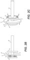
- Medical device 1' may be used in a similar manner as medical device 1, except a user may pull on distal portion 20 distally to unlock lock 30, rotate distal portion 20 (and shaft 24) or proximal portion 10, relative to the other, to a desired degree, and release distal portion 20 to revert lock 30 into a locked configuration.
- FIG. 3A illustrates a rotatable gyro 50 that may be included in medical device embodiments, including devices 1, 1' described above.
- rotatable gyro 50 surrounds a portion of guide 14 and working channel 22, and also holds a steering wire 60.
- Gyro 50 may be fitted around the area in which lumen 14' and working channel 22 meet.
- gyro 50 is not limited to such a position, and may also be fitted around, for example, portions of guide 14 within proximal portion 10.
- a handle may include gyro 50 fitted around guide 14 and channel 22, and lock 30 also fitted around channel 22.
- Each steering wire of a conventional medical device is a single piece routed from the handle to the distal end of a shaft.
- rotation of such steering wires, while rotating the shaft may result in damage to the steering wires due to the twisting from rotation.
- steering wire 60 is of two separate, decoupled wires, proximal wire 61 and distal wire 63, to help enable rotation of distal portion 20 (and shaft 24) without damaging steering wire 60, as described above.
- the proximal end of proximal wire 61 may be connected to any suitable controller, e.g., device 43 shown in FIG. 1 .
- proximal wire 61 is connected to, or integral with, a first termination/ferrule ball 62.
- the distal end of distal wire 63 connects to the distal end of shaft 24 to control articulation thereof.
- the proximal end of distal wire 63 is connected to, or integral with, a second termination/ferrule ball 64.
- Balls 62 and 64 may be of any suitable material, e.g., lead, and is not particularly limited.
- each ball 62, 64 may be a machined or heat treated end of corresponding wire 61, 63.
- ball 62, 64 are not particularly limited to being balls, and may be any suitable enlargement.
- wires 61 and 63 are not particularly limited, and may be any suitable cables or wires used for medical procedures (e.g., medical grade plastic or metal).
- Gyro 50 includes a proximal gyro 51 and a distal gyro 55, which are rotatably interlinked with one another.
- Proximal gyro 51 is a structure surrounding guide 14 and holding proximal wire 61.
- Distal gyro 55 is a structure surrounding distal working channel 22 and holding distal wire 63.
- Distal gyro 55 may be fixed around channel 22 so that it may be rotatable with channel 22, relative to proximal gyro 51.
- Proximal gyro 51 may be fixed to guide 14.
- Proximal gyro 51 includes a recess 52, and a flange 53 that protrudes proximally, thereby partially covering recess 51.
- Proximal gyro 51 further includes a flange 73 that is proximal to recess 52, and protrudes radially outward, relative to the remainder of proximal gyro 51.
- the distance by which flange 73 protrudes is not particularly limited, so long as it may be accommodated within device 1".
- Flange 73 includes a channel 74 at about the midpoint of its radial protrusion. Channel 74 runs parallel or about parallel to a longitudinal axis of guide 14. The width of channel 74 may be such that it accommodates for proximal wire 61, but is narrower than the diameter of first ball 62, which is distal to channel 74.
- Distal gyro 55 holds proximal wire 61 while also anchoring first ball 62, so that proximal wire 61 is inhibited from slipping out of channel 74 when pulled proximally.
- Distal gyro 55 includes a void 56 and a flange 57 that protrudes distally, thereby partially covering void 56.
- Distal gyro 55 also includes a flange 71 that is similar in many respects to flange 73.
- Flange 71 includes a channel 72 at about the midpoint of its radial protrusion.
- Flange 71 similar to flange 73, holds distal wire 63 while also anchoring second ball 64, so that distal wire 63 is inhibited from slipping out of channel 72 when distal gyro 55 is pulled proximally. It is noted that void 56, flange 57, recess 52, and flange 53 are annular, so they are in engagement around the circumferences of proximal gyro 51 and distal gyro 55.
- Proximal gyro 51 and distal gyro 55 may be in constant engagement with one another due to their interlocking.
- Distal gyro 55 is interlocked around flange 53 of proximal gyro 51, such that portions of distal gyro 55 and proximal gyro 51 tightly abut one another, while also allowing rotation of distal gyro 55 or proximal gyro 51, relative to the other.
- Flange 57 of distal gyro 55 and flange 53 of proximal gyro 51 hook against one another, as flange 57 remains within recess 52 of proximal flange 51, and flange 53 remains within void 56 of distal gyro 55.
- the hook-like features of flanges 53 and 57 inhibit proximal gyro 51 and distal gyro 55 from disengaging from one another.
- the dimensions of flanges 53, 57, recess 52, and void 56 are not particularly limited, and may be any suitable dimensions that allow for the above described rotatable, interlocked engagement between proximal gyro 51 and distal gyro 55.
- rotatable gyro 50 enables the rotation of proximal steering wire 61 or distal steering wire 63, as distal portion 20 or proximal portion 10 is rotated, relative to the other. Furthermore, the above configuration of gyro 50 enables the articulation of flexible shaft 24, via steering wire 60.
- Proximal wire 61, including first ball 62 may be pulled via actuation of any suitable controller, e.g., device 43 (not shown), which in turn pulls on proximal gyro 51 due to first ball 62 pulling against flange 73. Pulling on proximal gyro 51 results in distal gyro 53 being pulled, due to their interlocked engagement. This, in turn, pulls on distal steering wire 63, due to flange 71 pushing against second ball 64, and results in steering wire 63 pulling on the distal end of shaft 24, thereby enabling articulation thereof.
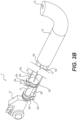
- FIG. 3B illustrates a medical device 1" including two rotatable gyros 50a and 50b, both of which are identical to rotatable gyro 50 of FIG. 3A .
- Gyros 50a and 50b respectively hold the two steering wires, 60a and 60b.
- the number of gyros included in medical devices is not particularly limited, and may be any suitable number that corresponds with the number of steering wires (e.g. one, two, or four) within a medical device embodiment.
- one gyro, rotatable gyro 50a may be positioned around the area in which the lumen (not shown) of guide 14 and working channel 22 meet, as described above for FIG. 3A .
- Suctioning may also be enabled in medical devices that include a rotatable working channel.
- Medical device 1′′′ as shown in FIG. 4 , is similar to device 1 in some respects. Like reference numerals refer to like parts. Differences between device 1 and device 1"' will be described below.
- working channel 12' is a rotatable tube that extends from proximal portion 10, through rotatable distal portion 20", to the distal end of a shaft (not shown). At least a portion of channel 12' may be fixed to the shaft. Thus, channel 12', as a whole, may rotate as distal portion 20" and the shaft also rotate.
- Working channel 12' includes a plurality of circular/oval-shaped openings 120 distributed about its circumference.
- openings 120 are sealed from the remaining, unopened portions of working channel 12', via sealing rings 13a and 13b.
- Rings 13a and 13b are fitted around the portions of working channel 12' that are adjacent to openings 120, with one ring 13a distal to openings 120 and the other ring 13b proximal to openings 120.
- Rings 13a and 13b may be fitted around working channel 12' so that they serve as a seal, while also enabling rotation of channel 12' within rings 13a and 13b.
- Rings 13a and 13b may be of any suitable material used for sealing purposes, e.g., rubber.
Landscapes
- Health & Medical Sciences (AREA)
- Life Sciences & Earth Sciences (AREA)
- Surgery (AREA)
- Engineering & Computer Science (AREA)
- Biophysics (AREA)
- Medical Informatics (AREA)
- Veterinary Medicine (AREA)
- Nuclear Medicine, Radiotherapy & Molecular Imaging (AREA)
- Optics & Photonics (AREA)
- Pathology (AREA)
- Radiology & Medical Imaging (AREA)
- Public Health (AREA)
- General Health & Medical Sciences (AREA)
- Biomedical Technology (AREA)
- Heart & Thoracic Surgery (AREA)
- Physics & Mathematics (AREA)
- Molecular Biology (AREA)
- Animal Behavior & Ethology (AREA)
- Pulmonology (AREA)
- Otolaryngology (AREA)
- Physiology (AREA)
- Mechanical Engineering (AREA)
- Surgical Instruments (AREA)
- Endoscopes (AREA)
- Ultra Sonic Daignosis Equipment (AREA)
Applications Claiming Priority (3)
| Application Number | Priority Date | Filing Date | Title |
|---|---|---|---|
| US202062969925P | 2020-02-04 | 2020-02-04 | |
| PCT/US2021/016386 WO2021158643A1 (fr) | 2020-02-04 | 2021-02-03 | Dispositif médical rotatif |
| EP21708497.9A EP4099887B1 (fr) | 2020-02-04 | 2021-02-03 | Dispositif médical rotatif |
Related Parent Applications (1)
| Application Number | Title | Priority Date | Filing Date |
|---|---|---|---|
| EP21708497.9A Division EP4099887B1 (fr) | 2020-02-04 | 2021-02-03 | Dispositif médical rotatif |
Publications (2)
| Publication Number | Publication Date |
|---|---|
| EP4582010A2 true EP4582010A2 (fr) | 2025-07-09 |
| EP4582010A3 EP4582010A3 (fr) | 2025-08-06 |
Family
ID=74759534
Family Applications (2)
| Application Number | Title | Priority Date | Filing Date |
|---|---|---|---|
| EP21708497.9A Active EP4099887B1 (fr) | 2020-02-04 | 2021-02-03 | Dispositif médical rotatif |
| EP25177519.3A Pending EP4582010A3 (fr) | 2020-02-04 | 2021-02-03 | Dispositif médical rotatif |
Family Applications Before (1)
| Application Number | Title | Priority Date | Filing Date |
|---|---|---|---|
| EP21708497.9A Active EP4099887B1 (fr) | 2020-02-04 | 2021-02-03 | Dispositif médical rotatif |
Country Status (9)
| Country | Link |
|---|---|
| US (3) | US11826018B2 (fr) |
| EP (2) | EP4099887B1 (fr) |
| JP (2) | JP7689969B2 (fr) |
| KR (1) | KR20220137044A (fr) |
| CN (1) | CN115397299A (fr) |
| AU (1) | AU2021217962A1 (fr) |
| CA (1) | CA3168809A1 (fr) |
| MX (1) | MX2022009436A (fr) |
| WO (1) | WO2021158643A1 (fr) |
Families Citing this family (6)
| Publication number | Priority date | Publication date | Assignee | Title |
|---|---|---|---|---|
| CN115460963A (zh) * | 2020-04-24 | 2022-12-09 | 安布股份有限公司 | 用于内窥镜的手柄 |
| EP4405021B1 (fr) * | 2021-09-22 | 2025-08-13 | Entellect Medical Holdings | Ensemble de commande de cathéter rotatif et déviable |
| WO2023049783A1 (fr) * | 2021-09-22 | 2023-03-30 | EnTellect Medical Holdings | Ensemble de commande de cathéter rotatif et pouvant être dévié |
| EP4183310A1 (fr) * | 2021-11-23 | 2023-05-24 | Ambu A/S | Endoscope comprenant un connecteur en y ayant un canal d'insertion d'instrument incurvé |
| CN118203286A (zh) * | 2022-12-15 | 2024-06-18 | 浙江逸镜医疗器械有限公司 | 一种内窥镜结构 |
| US12096922B1 (en) | 2023-10-25 | 2024-09-24 | Krueze Innovations LLC | Apparatus, methods, and systems for improving surgical control with a medical torquing device |
Family Cites Families (33)
| Publication number | Priority date | Publication date | Assignee | Title |
|---|---|---|---|---|
| JPH0628628B2 (ja) * | 1985-05-20 | 1994-04-20 | オリンパス光学工業株式会社 | 内視鏡 |
| US4750477A (en) * | 1987-02-20 | 1988-06-14 | Circon Corporation | Instrument control head |
| JPH065761Y2 (ja) * | 1988-04-25 | 1994-02-16 | 旭光学工業株式会社 | 内視鏡 |
| DE4101472C2 (de) * | 1991-01-19 | 1995-07-13 | Winter & Ibe Olympus | Endoskop zur transurethralen Resektion |
| US5486155A (en) * | 1994-07-15 | 1996-01-23 | Circon Corporation | Rotatable endoscope sheath |
| JPH09149877A (ja) * | 1995-09-27 | 1997-06-10 | Olympus Optical Co Ltd | 内視鏡保持装置 |
| US5810715A (en) * | 1995-09-29 | 1998-09-22 | Olympus Optical Co., Ltd. | Endoscope provided with function of being locked to flexibility of insertion part which is set by flexibility modifying operation member |
| US5810718A (en) * | 1997-02-14 | 1998-09-22 | Fuji Photo Optical Co., Ltd. | Coupler structure for tube units of endoscopes |
| US20020133077A1 (en) * | 2001-03-14 | 2002-09-19 | Edwardsen Stephen Dodge | Transesophageal ultrasound probe having a rotating endoscope shaft |
| JP3938719B2 (ja) * | 2002-05-24 | 2007-06-27 | オリンパス株式会社 | 内視鏡 |
| US6824509B2 (en) * | 2001-07-23 | 2004-11-30 | Olympus Corporation | Endoscope |
| US6692431B2 (en) * | 2001-09-07 | 2004-02-17 | Smith & Nephew, Inc. | Endoscopic system with a solid-state light source |
| WO2005060822A1 (fr) * | 2003-12-18 | 2005-07-07 | Olympus Corporation | Bouchon d'instrument de traitement pour endoscope et corps de bouchon pour instrument de traitement |
| DE202004014828U1 (de) * | 2004-09-21 | 2004-12-02 | Richard Wolf Gmbh | Endoskopisches Instrument |
| EP1887920A1 (fr) * | 2005-05-17 | 2008-02-20 | Wilson-Cook Medical Inc. | Dispositif de rinçage d'hemostase |
| US7648519B2 (en) | 2006-09-13 | 2010-01-19 | Cambridge Endoscopic Devices, Inc. | Surgical instrument |
| WO2008045374A2 (fr) * | 2006-10-05 | 2008-04-17 | Tyco Healthcare Group Lp | Ensemble poignée pour instruments endoscopiques articulés |
| EP2498668A4 (fr) * | 2009-11-13 | 2013-08-07 | Hologic Inc | Système d'accès avec un canal d'évacuation amovible |
| CN102858223B (zh) * | 2010-04-28 | 2015-04-29 | 奥林巴斯医疗株式会社 | 操作机构、内窥镜装置及导引导管 |
| EP2716203B1 (fr) * | 2011-06-01 | 2018-04-04 | Olympus Corporation | Endoscope |
| JP5296952B1 (ja) * | 2011-11-25 | 2013-09-25 | オリンパスメディカルシステムズ株式会社 | 内視鏡 |
| US20150025311A1 (en) * | 2013-03-15 | 2015-01-22 | Jeffrey S. Kadan | Small single-port arthroscopic lavage, directed tissue drying, biocompatible tissue scaffold and autologous regenerated cell placement delivery system |
| US9498112B1 (en) | 2013-03-15 | 2016-11-22 | Brent Stewart | Laryngoscope |
| JP5893812B1 (ja) * | 2014-07-17 | 2016-03-23 | オリンパス株式会社 | 内視鏡 |
| JP5993530B2 (ja) * | 2014-09-16 | 2016-09-14 | オリンパス株式会社 | 内視鏡 |
| US10667802B2 (en) * | 2015-06-05 | 2020-06-02 | Boston Scientific Scimed, Inc. | Devices and methods for joining tissue |
| US10779940B2 (en) * | 2015-09-03 | 2020-09-22 | Boston Scientific Scimed, Inc. | Medical device handle |
| US10765441B2 (en) * | 2016-01-29 | 2020-09-08 | Boston Scientific Scimed, Inc. | Devices for medical procedures and related methods of use |
| GB2553259B (en) * | 2016-05-17 | 2021-07-14 | Creo Medical Ltd | Control device for a surgical instrument |
| US20220273165A1 (en) * | 2017-09-25 | 2022-09-01 | Micronvision Corp | Portable and ergonomic endoscope with disposable cannula |
| US10792466B2 (en) * | 2017-03-28 | 2020-10-06 | Auris Health, Inc. | Shaft actuating handle |
| CN111225595B (zh) * | 2017-11-30 | 2023-01-24 | 奥林巴斯株式会社 | 插入装置、外装部件的连接构造、内窥镜 |
| US11090072B2 (en) * | 2018-03-12 | 2021-08-17 | Boston Scientific Limited | Medical devices and related methods |
-
2021
- 2021-02-03 EP EP21708497.9A patent/EP4099887B1/fr active Active
- 2021-02-03 KR KR1020227029961A patent/KR20220137044A/ko not_active Ceased
- 2021-02-03 MX MX2022009436A patent/MX2022009436A/es unknown
- 2021-02-03 CN CN202180024629.8A patent/CN115397299A/zh active Pending
- 2021-02-03 JP JP2022547066A patent/JP7689969B2/ja active Active
- 2021-02-03 EP EP25177519.3A patent/EP4582010A3/fr active Pending
- 2021-02-03 AU AU2021217962A patent/AU2021217962A1/en active Pending
- 2021-02-03 US US17/166,656 patent/US11826018B2/en active Active
- 2021-02-03 CA CA3168809A patent/CA3168809A1/fr active Pending
- 2021-02-03 WO PCT/US2021/016386 patent/WO2021158643A1/fr not_active Ceased
-
2023
- 2023-10-23 US US18/492,023 patent/US12369772B2/en active Active
-
2025
- 2025-05-28 JP JP2025088797A patent/JP2025113441A/ja active Pending
- 2025-06-27 US US19/252,688 patent/US20250318708A1/en active Pending
Also Published As
| Publication number | Publication date |
|---|---|
| US20250318708A1 (en) | 2025-10-16 |
| JP2023512300A (ja) | 2023-03-24 |
| EP4099887A1 (fr) | 2022-12-14 |
| US11826018B2 (en) | 2023-11-28 |
| WO2021158643A1 (fr) | 2021-08-12 |
| US20240041300A1 (en) | 2024-02-08 |
| CA3168809A1 (fr) | 2021-08-12 |
| JP2025113441A (ja) | 2025-08-01 |
| KR20220137044A (ko) | 2022-10-11 |
| JP7689969B2 (ja) | 2025-06-09 |
| CN115397299A (zh) | 2022-11-25 |
| EP4582010A3 (fr) | 2025-08-06 |
| EP4099887B1 (fr) | 2025-05-21 |
| US12369772B2 (en) | 2025-07-29 |
| MX2022009436A (es) | 2022-09-26 |
| AU2021217962A1 (en) | 2022-08-18 |
| US20210235973A1 (en) | 2021-08-05 |
Similar Documents
| Publication | Publication Date | Title |
|---|---|---|
| EP4099887B1 (fr) | Dispositif médical rotatif | |
| CN101932278B (zh) | 处理用内窥镜 | |
| EP2158932B1 (fr) | Cathéter à fil guide | |
| US20220354343A1 (en) | Medical device systems | |
| JP2007268270A (ja) | 内視鏡用付属装置取付器具 | |
| CA3166797A1 (fr) | Dispositif medical rotatif | |
| EP3415073B1 (fr) | Dispositifs de couplage de bronchoscopie | |
| EP4465867A1 (fr) | Gaine orientable et fixation d'endoscope réglable | |
| US20250090198A1 (en) | Medical device having a rotatable working channel and related methods of use | |
| US20200345211A1 (en) | Housing Assembly for Periodontal Endoscopic Probe | |
| CN222018421U (zh) | 一种导管导丝递送装置 | |
| EP4623796A2 (fr) | Systèmes et dispositifs médicaux | |
| TW202417071A (zh) | 醫療裝置支撐裝置 | |
| CN217960294U (zh) | 通过支撑定位的无菌保护套及手术机器人系统 |
Legal Events
| Date | Code | Title | Description |
|---|---|---|---|
| PUAI | Public reference made under article 153(3) epc to a published international application that has entered the european phase |
Free format text: ORIGINAL CODE: 0009012 |
|
| STAA | Information on the status of an ep patent application or granted ep patent |
Free format text: STATUS: REQUEST FOR EXAMINATION WAS MADE |
|
| REG | Reference to a national code |
Ref country code: DE Ref legal event code: R079 Free format text: PREVIOUS MAIN CLASS: A61B0001005000 Ipc: A61B0001000000 |
|
| PUAL | Search report despatched |
Free format text: ORIGINAL CODE: 0009013 |
|
| 17P | Request for examination filed |
Effective date: 20250520 |
|
| AC | Divisional application: reference to earlier application |
Ref document number: 4099887 Country of ref document: EP Kind code of ref document: P |
|
| AK | Designated contracting states |
Kind code of ref document: A2 Designated state(s): AL AT BE BG CH CY CZ DE DK EE ES FI FR GB GR HR HU IE IS IT LI LT LU LV MC MK MT NL NO PL PT RO RS SE SI SK SM TR |
|
| AK | Designated contracting states |
Kind code of ref document: A3 Designated state(s): AL AT BE BG CH CY CZ DE DK EE ES FI FR GB GR HR HU IE IS IT LI LT LU LV MC MK MT NL NO PL PT RO RS SE SI SK SM TR |
|
| RIC1 | Information provided on ipc code assigned before grant |
Ipc: A61B 1/00 20060101AFI20250702BHEP Ipc: A61B 1/267 20060101ALI20250702BHEP Ipc: A61B 1/012 20060101ALI20250702BHEP Ipc: A61B 1/005 20060101ALI20250702BHEP |
|
| RIN1 | Information on inventor provided before grant (corrected) |
Inventor name: GRAY, JEFF Inventor name: WALES, RYAN Inventor name: BRECHBIEL SCOTT Inventor name: MANSFIELD RICHARD Inventor name: SMITH, PAUL |
|
| STAA | Information on the status of an ep patent application or granted ep patent |
Free format text: STATUS: EXAMINATION IS IN PROGRESS |