EP4582002A1 - Lave-vaisselle - Google Patents
Lave-vaisselle Download PDFInfo
- Publication number
- EP4582002A1 EP4582002A1 EP23885968.0A EP23885968A EP4582002A1 EP 4582002 A1 EP4582002 A1 EP 4582002A1 EP 23885968 A EP23885968 A EP 23885968A EP 4582002 A1 EP4582002 A1 EP 4582002A1
- Authority
- EP
- European Patent Office
- Prior art keywords
- storage compartment
- housing
- door
- solid
- tub
- Prior art date
- Legal status (The legal status is an assumption and is not a legal conclusion. Google has not performed a legal analysis and makes no representation as to the accuracy of the status listed.)
- Pending
Links
Images


Classifications
-
- A—HUMAN NECESSITIES
- A47—FURNITURE; DOMESTIC ARTICLES OR APPLIANCES; COFFEE MILLS; SPICE MILLS; SUCTION CLEANERS IN GENERAL
- A47L—DOMESTIC WASHING OR CLEANING; SUCTION CLEANERS IN GENERAL
- A47L15/00—Washing or rinsing machines for crockery or tableware
- A47L15/42—Details
- A47L15/44—Devices for adding cleaning agents; Devices for dispensing cleaning agents, rinsing aids or deodorants
- A47L15/4409—Devices for adding cleaning agents; Devices for dispensing cleaning agents, rinsing aids or deodorants by tipping containers or opening their lids, e.g. with the help of a programmer
-
- A—HUMAN NECESSITIES
- A47—FURNITURE; DOMESTIC ARTICLES OR APPLIANCES; COFFEE MILLS; SPICE MILLS; SUCTION CLEANERS IN GENERAL
- A47L—DOMESTIC WASHING OR CLEANING; SUCTION CLEANERS IN GENERAL
- A47L15/00—Washing or rinsing machines for crockery or tableware
- A47L15/42—Details
-
- A—HUMAN NECESSITIES
- A47—FURNITURE; DOMESTIC ARTICLES OR APPLIANCES; COFFEE MILLS; SPICE MILLS; SUCTION CLEANERS IN GENERAL
- A47L—DOMESTIC WASHING OR CLEANING; SUCTION CLEANERS IN GENERAL
- A47L15/00—Washing or rinsing machines for crockery or tableware
- A47L15/42—Details
- A47L15/4251—Details of the casing
- A47L15/4257—Details of the loading door
-
- A—HUMAN NECESSITIES
- A47—FURNITURE; DOMESTIC ARTICLES OR APPLIANCES; COFFEE MILLS; SPICE MILLS; SUCTION CLEANERS IN GENERAL
- A47L—DOMESTIC WASHING OR CLEANING; SUCTION CLEANERS IN GENERAL
- A47L15/00—Washing or rinsing machines for crockery or tableware
- A47L15/42—Details
- A47L15/4251—Details of the casing
- A47L15/4274—Arrangement of electrical components, e.g. control units or cables
-
- A—HUMAN NECESSITIES
- A47—FURNITURE; DOMESTIC ARTICLES OR APPLIANCES; COFFEE MILLS; SPICE MILLS; SUCTION CLEANERS IN GENERAL
- A47L—DOMESTIC WASHING OR CLEANING; SUCTION CLEANERS IN GENERAL
- A47L15/00—Washing or rinsing machines for crockery or tableware
- A47L15/42—Details
- A47L15/44—Devices for adding cleaning agents; Devices for dispensing cleaning agents, rinsing aids or deodorants
- A47L15/4436—Devices for adding cleaning agents; Devices for dispensing cleaning agents, rinsing aids or deodorants in the form of a detergent solution made by gradually dissolving a powder detergent cake or a solid detergent block
-
- A—HUMAN NECESSITIES
- A47—FURNITURE; DOMESTIC ARTICLES OR APPLIANCES; COFFEE MILLS; SPICE MILLS; SUCTION CLEANERS IN GENERAL
- A47L—DOMESTIC WASHING OR CLEANING; SUCTION CLEANERS IN GENERAL
- A47L15/00—Washing or rinsing machines for crockery or tableware
- A47L15/42—Details
- A47L15/44—Devices for adding cleaning agents; Devices for dispensing cleaning agents, rinsing aids or deodorants
- A47L15/4463—Multi-dose dispensing arrangements
-
- A—HUMAN NECESSITIES
- A47—FURNITURE; DOMESTIC ARTICLES OR APPLIANCES; COFFEE MILLS; SPICE MILLS; SUCTION CLEANERS IN GENERAL
- A47L—DOMESTIC WASHING OR CLEANING; SUCTION CLEANERS IN GENERAL
- A47L15/00—Washing or rinsing machines for crockery or tableware
- A47L15/42—Details
- A47L15/44—Devices for adding cleaning agents; Devices for dispensing cleaning agents, rinsing aids or deodorants
- A47L15/449—Metering controlling devices
-
- A—HUMAN NECESSITIES
- A47—FURNITURE; DOMESTIC ARTICLES OR APPLIANCES; COFFEE MILLS; SPICE MILLS; SUCTION CLEANERS IN GENERAL
- A47L—DOMESTIC WASHING OR CLEANING; SUCTION CLEANERS IN GENERAL
- A47L15/00—Washing or rinsing machines for crockery or tableware
- A47L15/42—Details
- A47L15/48—Drying arrangements
- A47L15/488—Connections of the tub with the ambient air, e.g. air intake or venting arrangements
-
- A—HUMAN NECESSITIES
- A47—FURNITURE; DOMESTIC ARTICLES OR APPLIANCES; COFFEE MILLS; SPICE MILLS; SUCTION CLEANERS IN GENERAL
- A47L—DOMESTIC WASHING OR CLEANING; SUCTION CLEANERS IN GENERAL
- A47L2501/00—Output in controlling method of washing or rinsing machines for crockery or tableware, i.e. quantities or components controlled, or actions performed by the controlling device executing the controlling method
- A47L2501/07—Consumable products, e.g. detergent, rinse aids or salt
Definitions
- the disclosure relates to a dishwasher, and more particularly, to a dishwasher including a device configured to input detergent.
- a dishwasher is a device that automatically removes food residues and the like on dishes using detergent and wash water.
- the dishwasher includes a main body, a washing chamber formed by a tub disposed inside the main body, a storage container disposed inside the washing chamber to store dishes, and a spray unit configured to spray wash water to the storage container.
- the storage container may be usually provided in two or three stages, and the spray unit may be provided in plurality and disposed to correspond to the storage container so as to spray wash water to each place, in which each storage container is disposed.
- the dishwasher may include a washing process, a rinsing process, and a drying process.
- the spray unit may spray wash water, and at the same time, an automatic detergent dispenser may input detergent to the tub. Accordingly, dishes may be washed.
- wash water may be sprayed to remove the detergent.
- moisture remaining in the dishes may be removed.
- the automatic detergent dispenser of the dishwasher may include a storage compartment so as to store various types of detergents, such as powder detergent or liquid detergent, in the storage compartment.
- a dishwasher includes a tub; a door configured to open and close the tub, the door including an outer frame forming an outer surface of the door, and an inner frame coupled to the outer frame and forming an inner surface of the door, with an inner space between the outer frame and the inner frame; and an automatic detergent dispenser coupled to the inner frame and configured to dispense a solid detergent toward an inside of the tub while the tub is closed by the door, the automatic detergent dispenser including a storage compartment in which a plurality of solid detergents are stackable so as to be loaded along one direction, and a discharge duct including a discharge hole formed to communicate with an inner space, the discharge duct configured to discharge air, which flows from the tub into the automatic detergent dispenser, to the inner space through the discharge hole.
- the discharge duct may extend parallel to the one direction along which the plurality of solid detergents are loaded, and the discharge hole may be formed at one side of the discharge duct with respect to the one direction.
- the discharge duct may be disposed in a direction perpendicular to the one direction with respect to the storage compartment.
- the automatic detergent dispenser may include a discharge hole cover covering the discharge hole from an outside of the discharge duct.
- the discharge hole cover may include a cover portion facing the discharge hole at a position spaced apart from the discharge hole.
- the automatic detergent dispenser may include an air discharge guide to guide air discharged through the discharge hole to an outside of the discharge hole cover, and the air discharge guide may be inclined downward toward the outer frame while the tub is closed by the door.
- the automatic detergent dispenser may include a housing coupled to the inner frame and in which the storage compartment and the discharge duct are disposed, a driver configured to drive the automatic detergent dispenser to discharge one solid detergent among the plurality of solid detergents into the tub, the driver disposed inside the housing, a control device configured to control the driver, and a wire configured to electrically connect the driver and the control device, at least a portion of the wire being disposed along the discharge duct.
- the wire may pass through the discharge hole
- the housing may include a control device cover to cover a portion of the wire, the discharge hole, and the control device.
- the automatic detergent dispenser may include a housing coupled to the inner frame, the housing may include a drain groove formed to have a concave shape on an outer surface of the housing, the storage compartment and the discharge duct may be disposed inside the housing, the discharge hole may be disposed on the outer surface of the housing, and the drain groove may be configured to prevent water, which flows from the tub into the inner space, from flowing into the discharge hole.
- the discharge hole may be formed on one surface of the housing at a side toward the outer frame
- the housing may include a housing rib disposed along the drain groove and formed to have a protruding shape, the housing rib may be disposed in a direction toward the outer frame with respect to the drain groove.
- the storage compartment may include a storage compartment discharge hole to communicate with the inner space.
- the storage compartment discharge hole may be at one side of the storage compartment along the one direction in which the plurality of solid detergents are loaded.
- the automatic detergent dispenser may include an inlet communicating with the tub and configured so that one solid detergent among the plurality of solid detergents to be discharged, the one solid detergent having been discharged from the storage compartment, into the tub, and, while the tub is closed by the door, the plurality of solid detergents may be stacked in a vertical direction inside the storage compartment, the inlet may be disposed below the discharge duct, and the discharge hole may be formed at an upper side of the discharge duct.
- the automatic detergent dispenser may include a seating member to seat a solid detergent discharged from the storage compartment, and from which the seated solid detergent may be discharged into the tub, and the discharge duct may extend between the seating member and the discharge hole.
- a dishwasher may include a main body, a tub provided inside the main body, a door configured to open and close the tub, and an automatic detergent dispenser arranged on the door and configured to input a solid detergent toward an inside of the tub while the tub is closed by the door.
- the automatic detergent dispenser may include a storage compartment provided to allow a plurality of solid detergents to be stacked and loaded, and a housing coupled to the door and in which the storage compartment is provided.
- the housing may include a drain groove formed along at least a portion of an outer edge of the housing to include a concave shape and provided to drain water, which flows from the tub, from the housing to a lower side of the door while the door is closed.
- the housing may further include a housing rib disposed along the drain groove and including a protruding shape.
- the housing rib may be disposed in a direction toward an outer surface of the door with respect to the drain groove.
- the door may include an outer frame forming an outer surface of the door, an inner frame coupled to the outer frame and forming an inner surface of the door, and an inner space arranged between the outer frame and the inner frame.
- a portion of the housing may be disposed in the inner space.
- the drain groove may be disposed in the inner space to drain water, which flows from the tub into the inner space, to a lower side of the inner space.
- the housing may further include a discharge hole formed to communicate with the inner space.
- the drain groove may be provided to prevent water, which flows from the tub, from flowing into the discharge hole.
- a dishwasher may include a main body, a tub provided inside the main body, a door configured to open and close the tub and including an inner space provided to communicate with the tub in response to the tub being closed, and an automatic detergent dispenser coupled to the door and configured to input a solid detergent toward an inside of the tub while the tub is closed by the door.
- the automatic detergent dispenser may include a housing including a drain groove formed on an outer surface of the housing, the housing coupled to the door, a storage compartment provided inside the housing and provided to allow a plurality of the solid detergents to be loaded therein, and a discharge hole arranged on the outer surface of the housing and provided to allow an inside of the housing and an inside of the door to communicate with each other.
- the drain groove may be provided to drain water, which flows from the tub into the inner space, to a lower side of the inner space so as to prevent the water from flowing into the discharge hole.
- an automatic detergent dispenser of a dishwasher may include a storage, and thus a plurality of solid detergents may be stacked and loaded in the storage compartment of the automatic detergent dispenser.
- An automatic detergent dispenser of a dishwasher may include an ejector configured to move one of a plurality of solid detergents loaded in a storage compartment to an outside of the storage compartment, and thus the solid detergent may be input during a washing process.
- An automatic detergent dispenser of a dishwasher may include a discharge duct formed to communicate with an inner space of a door of the dishwasher, and thus air introduced from a tub into the automatic detergent dispenser may be discharged to an outside of the automatic detergent dispenser.
- An automatic detergent dispenser of a dishwasher may include a discharge duct provided to discharge air flowing from a tub, and thus it is possible to prevent damage to the automatic detergent dispenser and to increase a lifetime of the automatic detergent dispenser.
- An automatic detergent dispenser of a dishwasher may include a drain groove, and thus it is possible to discharge water to an inner space between an inner frame and an outer frame.
- An automatic detergent dispenser of a dishwasher may include a housing rib, and thus it is possible to prevent water collected in a drain groove from being discharged to an outside of the drain groove.
- a singular expression may include a plural expression unless they are definitely different in a context.
- a or B at least one of A or/and B,” or “one or more of A or/and B,” A, B or C,” “at least one of A, B or/and C,” or “one or more of A, B or/and C,” and the like used herein may include any and all combinations of one or more of the associated listed items.
- an element e.g., a first element
- another element e.g., a second element
- the first element may be connected to the second element, directly (e.g., wired), wirelessly, or through a third element.
- the door 20 may be rotatably hinged to a lower portion of the main body 10.
- a rotation axis of the hinge 25 may extend in the second direction Y, which is the left and right direction of the main body 10, to allow the door 20 to be rotated in the front and rear directions in front of the main body 10.
- the door 20 may be hinged to a hinge arranged on the left or right side of the main body 10 with respect to the second direction Y.
- the door 20 may be provided to be rotated from the second direction Y to the first direction X by the hinge arranged on the left and/or right side of the main body 10.
- the solid detergent means a solid detergent that is formed to have a predetermined shape.
- the solid detergent may have an approximate block shape, and thus the solid detergent may be referred to by various terms such as detergent block and block-type detergent.
- the shape of the solid detergent is not limited to a specific shape or size, and may have various shapes.
- the detergent box 90 may be provided to accommodate powder detergent or liquid detergent.
- the detergent box 90 may be provided to allow detergent to be input into the tub 12 while the dishwasher 1 washes dishes.
- the dishwasher 1 may be configured to allow one detergent, which is selected by a user between detergent stored in the detergent box 90 and solid detergents loaded in the automatic detergent dispenser 1000, to be input to the tub 12.
- the automatic detergent dispenser 1000 may be disposed on the inner surface 21 of the door 20.
- the automatic detergent dispenser 1000 may be provided to be coupled to the inner surface 21 of the door 20.
- the detergent box 90 may be disposed on the inner surface 21 of the door 20.
- the automatic detergent dispenser 1000 and the detergent box 90 may be arranged in the third direction Z, which is the vertical direction.
- the automatic detergent dispenser 1000 may be provided to be rotated together with the door 20 by the rotation of the door 20.
- the automatic detergent dispenser 1000 may be interlocked with the door 20 so as to be moved between a first position 1000A of the automatic detergent dispenser 1000 corresponding to the first position 20A of the door 20, and a second position 1000B of the automatic detergent dispenser 1000 corresponding to the second position 20B of the door 20.
- the automatic detergent dispenser 1000 When the door 20 closes the tub 12, the automatic detergent dispenser 1000 may be disposed at the first position 1000A, and when the door 20 opens the tub 12, the automatic detergent dispenser 1000 may be disposed at the second position 1000B.
- a user can load a plurality of solid detergents into the automatic detergent dispenser 1000 when the automatic detergent dispenser 1000 is disposed at the second position 1000B.
- the automatic detergent dispenser 1000 may include a housing 1100.
- the housing 1100 may include a first housing 1110 forming the storage compartment 1200 to be described later and a second housing 1120 coupled to the first housing 1110.
- the first housing 1110 may be provided to be coupled to the inner surface 21 of the door 20.
- the second housing 1120 may be coupled to the first housing 1110 in the first direction X when the automatic detergent dispenser 1000 is disposed at the first position 1000A.
- the cross-sectional area S of the storage compartment 1200 may be formed by a pair of sides having a horizontal length L1 extending in the second direction Y and a pair of sides having a vertical length L2 extending in the first direction X when the automatic detergent dispenser 1000 is disposed at the first position A.
- the horizontal length L1 and the vertical length L2 may be defined based on the dimension provided in the first direction X and the second direction Y, and the horizontal length may also be defined as L2, and the vertical length may also be defined as L1.
- the solid detergent D When the solid detergent D is loaded into the storage compartment 1200, the solid detergent D may be arranged to allow one side having the horizontal length d1 of the solid detergent D to correspond to a side having the horizontal length L1 of the cross-sectional area S of the storage compartment 1200, and to allow the other side having the vertical length d2 of the solid detergent D to correspond to a side having the vertical length L2 of the cross-sectional area S of the storage compartment 1200.
- the horizontal length L1 of the cross-sectional area S may be formed to be greater than the vertical length L2. Further, because the horizontal length d1 of the solid detergent is formed to be greater than the length of the height h of the solid detergent D, the vertical length L2 of the cross-sectional area S may be formed to be greater than the height h of the solid detergent D.
- the horizontal length L1 of the cross-sectional area S may be greater than the horizontal length d1 of the solid detergent D by approximately 10% to 30% of the horizontal length d1 of the solid detergent D.
- the vertical length L2 of the cross-sectional area S may be greater than the vertical length d2 of the solid detergent D by approximately 10% to 30% of the vertical length d2 of the solid detergent D.
- the cross-sectional area S of the storage compartment 1200 may be formed to have the above-mentioned value.
- the solid detergent disposed at the lowest position in the third direction Z among the plurality of stacked solid detergents when the solid detergent disposed at the lowest position in the third direction Z among the plurality of stacked solid detergents is moved downward, the solid detergent may be stuck on the inside of the storage compartment 1200 without being seated on the lower surface 1220 of the storage compartment 1200. Accordingly, even when the ejector 1300 is driven, a pressing member 1312a, which will be described later, may not easily press the solid detergent disposed at the lowest position in the third direction Z, and thus the solid detergent may not be discharged from the storage compartment 1200.
- the solid detergent may be rotated or moved in an oblique direction with respect to the third direction Z when being moved downward, and thus the solid detergent may be moved in the first direction X and the second direction Y without being moved in the third direction. Accordingly, the stacked arrangement of the plurality of solid detergents may not be maintained.
- the horizontal and vertical lengths L1 and L2 of the cross-sectional area S may be formed to be greater than the horizontal and vertical lengths d1 and d2 of the solid detergent D by approximately 10 % to 30% of the horizontal and vertical lengths d1 and d2 of the solid detergent D.
- the automatic detergent dispenser 1000 may have a predetermined thickness in the direction in which the vertical length L2 extends.
- the automatic detergent dispenser 1000 may protrude from the door 20 toward the inside of the tub 12 in the first direction X and thus the inner space of the tub 12 may be reduced.
- the lower basket 51 when the door 20 is disposed at the first position 20A, the lower basket 51 may collide with the automatic detergent dispenser 1000 with respect to the first direction X.
- the automatic detergent dispenser 1000 may be arranged to be spaced apart from the lower basket 51 in the first direction X when the automatic detergent dispenser 1000 is disposed at the first position 1000A.
- the automatic detergent dispenser 1000 when the automatic detergent dispenser 1000 is disposed at the first position 1000A, the automatic detergent dispenser 1000 may be arranged to be spaced apart from the intermediate basket 52 with respect to the first direction X.
- the door 20 is disposed at the second position 20B, and accordingly, the lower basket 51 may be withdrawn toward the front of the tub 12 in the first direction X.
- the withdrawal of the lower basket 51 may be limited by the thickness of the automatic detergent dispenser 100 because the automatic detergent dispenser 1000 has a predetermined thickness in the extension direction of the vertical length L2.
- the automatic detergent dispenser 1000 may be provided to be coupled to the inner surface 21 of the door 20. When the automatic detergent dispenser 1000 is coupled to the inner surface 21, at least a portion of the automatic detergent dispenser 1000 may be inserted into the inside of the door 20 in the first direction X.
- the cam member 1310 may include a presser 1312a provided to protrude from a rim of the cam member 1310 and configured to press the solid detergent while being rotated by the rotation of the cam member 1310.
- the presser 1312a may be rotated according to the rotation of the cam member 1310 and moved into the storage compartment 1200, and configured to press one solid detergent, which is disposed at the lowest position in the third direction Z among the plurality of solid detergents stacked in the third direction Z, so as to be moved to the outlet 1210.
- the cam member 1310 may move the solid detergent by pressing the solid detergent toward the direction of rotation of the cam member 1310.
- the right side in FIG. 8 may be a direction corresponding to the left side in FIG. 1
- the left side in FIG. 8 may be a direction corresponding to the right side in FIG. 1
- the left and right sides in FIG. 1 may be opposite to the left and right sides in FIG. 8 with respect to the second direction Y.
- it will be described based on the left and right sides shown in FIG. 8 .
- cam member 1310 to be described below will be described as an example of the cam member 1310 of the ejector 1300 disposed on the left side of the second direction Y shown in FIG. 8 .
- the ejector 1300 may be disposed below the storage compartment 1200, and thus when a rotation direction of the cam member 1310 is a clockwise direction, the cam member 1310 may move a solid detergent, which is seated on the lower surface 1220 of the storage compartment 1200, to the right side while the cam member 1310 rotates clockwise.
- the storage compartment outlet 1210 may be disposed below the right surface 1230 of the storage compartment 1200.
- the storage compartment 1200 may include a penetration member 1221 formed on the lower surface 1220 of the storage compartment 1200 and provided to allow the presser 1312a to be moved from the outside of the storage compartment 1200 to the inside of the storage compartment 1200.
- the penetration member 1221 may be provided to extend not only to the lower surface 1220 of the storage compartment 1200 but also to the lower side of the right surface 1230 and the left surface 1240 of the storage compartment 1200.
- the presser 1312a may be rotated by the rotation of the cam member 1310 and moved into the storage compartment 1200 through the lower side of the left surface 1240 and the penetration member 1221 of the lower surface 1220, and then moved to the outside of the storage compartment 1200 through the lower side of the right surface 1230 and the penetration member 1221 of the lower surface 1220 according to the rotation of the cam member 1310.
- the penetration member 1221 may be provided in such a way that at least a portion of the lower surface 1220 is opened, as illustrated in FIG. 7 . As at least a portion of the lower surface 1220 is opened, the cam member 1310 disposed below the storage compartment 1200 may be rotated and the presser 1312a may be moved into the storage compartment 1200 through the penetration member 1221.
- the penetration member 1221 may be provided in such a way that not all but at least a portion of the lower surface 1220 is opened For example, an area of a portion, in which the penetration member 1221 is formed, in the lower surface 1220 may be less than an area of a portion, which is closed in the third direction Z, in the lower surface 1220.
- the lower surface 1222 closed in the third direction Z is referred to as a support surface 1222. This is because the support surface 1222 supports the solid detergent located at the lowest position in the third direction Z.
- the penetration member 1221 may be provided to extend from the center of the lower surface 1220 with respect to the first direction X to the second direction Y. Accordingly, the front and rear sides of the penetration member 1221 with respect to the first direction X may be provided as the support surface 1222.
- the support surface 1222 may support the solid detergent located at the lowest position in the third direction Z to allow the solid detergent to be disposed adjacent to the lower surface 1220, and thus the presser 1312a may easily press the solid detergent while the presser 1312a is moved through the penetration member 1221.
- the solid detergent when the solid detergent is moved to the outside of the storage compartment 1200 by the presser 1312a, the solid detergent may be moved in the second direction Y in a substantially horizontal state with respect to the third direction Z.
- the support surface 1222 may guide the solid detergent, which is moved in the second direction Y, to be moved in a horizontal state with respect to the third direction Z.
- the solid detergent D may be loaded into the storage compartment 1200 in a state in which a lower surface (us) of the solid detergent D in the third direction Z is in contact with the support surface 1222.
- the lower surface (us) of the solid detergent D may be guided by the support surface 1222 and then moved to the storage compartment outlet 1210 while the solid detergent D is maintained in a substantially horizontal state with respect to the third direction Z.
- the solid detergent When the solid detergent is moved in the second direction Y while being inclined with respect to the third direction Z, the solid detergent may be rotated, or moved to another direction without being moved to the second direction Y by the center of gravity. Accordingly, the solid detergent may not be moved toward the storage compartment outlet 1210 and may not be discharged to the outside of the storage compartment 1200.
- the rim of the cam member 1310 with respect to a rotation direction of the cam member 1310 may include a plurality of cam regions that is partitioned in the rotation direction of the cam member 1310.
- a cam region, in which a rim having a shortest radius from a rotating shaft 1313 of the cam member 1310 is disposed, among the plurality of cam regions is defined as a first cam region 1310A1
- the first cam region 1310A1 may be disposed on an upper end of the cam member 1310 when the dishwasher 1 does not perform the washing process.
- the presser 1312a may protrude to a predetermined height in a radial direction of the cam member 1310 with respect to the first cam region 1310A1.
- the presser 1312a may protrude to a predetermined height in the radial direction of the cam member 1310 with respect to the first cam region 1310A1, so as to allow a pressing force, which is capable of transferring the solid detergent D to the storage compartment outlet 1210, to be transferred to the solid detergent D.
- the presser 1312a may protrude to a predetermined height in the radial direction of the cam member 1310 with respect to the first cam region 1310A1, and thus when the cam member 1310 is rotated, the presser 1312a may press the solid detergent D, which is disposed at the lowest position in the third direction Z without pressing a solid detergent disposed above the solid detergent D at the lowest position.
- the first cam region 1310A1 of the cam member 1310 When the first cam region 1310A1 of the cam member 1310 is disposed on the upper end of the cam member 1310, the first cam region 1310A1 may be disposed at a lower position than the support surface 1222 in the third direction Z. This is to allow, when the solid detergent located at the lowest position among the plurality of solid detergents is disposed on the lower surface 1220 of the storage compartment 1200, the solid detergent to be located in the storage compartment 1200 in a substantially horizontal state with respect to the third direction Z while preventing one side of the solid detergent from being pressed upward with respect to the third direction Z by the cam member 1310.
- a cam member 1310' of an ejector 1300' disposed on the right side with respect to the second direction Y shown in FIG. 8 may be configured to be rotatable counterclockwise with respect to the direction shown in FIG 8 . Accordingly, the solid detergent loaded in the storage compartment 1200' disposed on the right side may be provided to be discharged to the left side of the storage compartment 1200'. This will be described later in detail.
- the rotating shaft 1313 of the cam member 1310 may be provided to extend in the first direction X when the automatic detergent dispenser 1000 is disposed at the first position 1000A.
- the cam member 1310 may be disposed in such a way that the radial direction of the cam member 1310 is disposed in a direction perpendicular to the first direction X, and accordingly, when the cam member 1310 is disposed inside the housing 1100, a volume of the cam member 1310 may be minimized in the first direction X. As described above, this is to maximize the volume of the washing chamber C in the first direction X.
- the ejector 1300 may include the driving motor 1320 configured to generate a rotational force to drive the cam member 1310.
- the driving motor 1320 may be arranged in such a way that a rotating shaft 1321 of the driving motor 1320 extends in a direction substantially perpendicular to the first direction X when the automatic detergent dispenser 1000 is disposed at the first position 1000A. Accordingly, when the driving motor 1320 is disposed inside the housing 1100, a volume of the driving motor 1320 in the first direction X may be minimized. As described above, this is to maximize the volume of the washing chamber C in the first direction X.
- the ejector 1300 may include the transmission member 1330 configured to transmit a rotational force generated by the driving motor 1320 to the pressing member 1310.
- the transmission member 1330 may include a plurality of gears. Because the rotating shaft 1313 of the cam member 1310 is arranged to extend in the first direction X and the rotating shaft 1321 of the driving motor 1320 is arranged to extend in a direction perpendicular to the first direction X, the transmission member 1330 may include a worm gear configured to vertically change a transmission direction of the driving force. For example, the transmission member 1330 may include a bevel gear.
- the transmission member 1330 includes a worm gear, it is possible to prevent the cam member 1310 from being arbitrarily rotated by an external force.
- the worm gear of the transmission member 1330 is arranged to extend in a direction perpendicular to the first direction X in which the rotating shaft 1313 of the cam member 1310 extends, and thus when the transmission member 1330 is arranged in the housing 1100, a volume of the transmission member 1330 in the first direction X may be minimized. As described above, this is to maximize the volume of the washing chamber C in the first direction X.
- the transmission member 1330 may connect the cam member 1310 and the driving motor 1320 to transfer the rotational force generated by the driving motor 1320 to the cam member 1310, and at this time, the transmission member 1330 may be configured to allow the cam member 1310 to be rotated with an appropriate rotational speed. For example, the transmission member 1330 may be configured to reduce the rotational speed of the rotating shaft 1321 of the driving motor 1320.
- the transmission member 1330 may be configured in various ways according to design factors such as a target rotational speed of the cam member 1310 and a rotational speed of the driving motor 1320.
- the automatic detergent dispenser 1000 may include a holder 1500 provided to allow the plurality of solid detergents to be maintained in the stacked state inside the storage compartment 1200 when the automatic detergent dispenser 1000 is disposed at the first position 1000A and the second position 1000B or during the automatic detergent dispenser 1000 is moved between the first position 1000A and the second position 1000B.
- the holder 1500 may be moved in a direction, in which the long side 1201 of the storage compartment 1200 extends, by guides formed on the both side surfaces 1230 and 1240 of the storage compartment 1200.
- the downward movement of the plurality of solid detergents may be limited.
- the holder 1500 may guide the downward movement of the plurality of solid detergents by pressing the plurality of solid detergents downward.
- the automatic detergent dispenser 1000 may be provided to allow the plurality of solid detergents to be easily and sequentially discharged from the bottom in the direction of gravity as the plurality of solid detergents is disposed in the direction of gravity.
- the holder 1500 may press the plurality of solid detergents D to the stacking direction, and when the stacking direction is different from the gravity direction, the holder 1500 may support the plurality of solid detergents D so as to maintain the arrangement of the plurality of solid detergents D.
- the movement of the plurality of solid detergents in the direction of gravity may be restricted.
- the solid detergent which is disposed at the lowest position in the third direction Z among the plurality of solid detergents, may be abnormally seated on the lower surface 1220 of the storage compartment 1200, and thus the solid detergent may not be discharged to the outside of the storage compartment 1200 by the ejector 1300.
- That the solid detergent is abnormally seated on the lower surface 1220 means a state in which, when the solid detergent is placed on the lower surface 1220, the ejector 1300 fails to press the solid detergent or means that the solid detergent is placed at a position in which the solid detergent is prevented from being discharged to the outside of the storage compartment 1200 even when the solid detergent is pressed by the ejector 1300.
- the holder 1500 may prevent the stacked arrangement of the plurality of solid detergents from being broken when the stacking direction of the plurality of solid detergents is directed to a direction different from the third direction Z due to the movement of the door 20.
- the holder 1500 may be provided to maintain the stacked arrangement of the plurality of solid detergents while the door 20 is moved from the first position 20A to the second position 20B, or even when the door 20 is disposed at the second position 20B.
- the holder 1500 may be provided to support the solid detergent disposed at the highest position in the third direction Z among the plurality of solid detergents.
- the holder 1500 may be provided to be fixed at a position adjacent to the solid detergent disposed at the highest position in the third direction Z among the plurality of solid detergents.
- the movement of the solid detergent, which is disposed at the highest position in the third direction Z among the plurality of solid detergents may be blocked by the temporarily fixed holder 1500, and thus it is possible to prevent the solid detergent, which is disposed at the highest position in the third direction Z among the plurality of solid detergents, from being separated from the stacked arrangement.
- the storage compartment 1200 may include a guide rail 1290 provided to guide the movement of the holder 1500 inside the storage compartment 1200.
- the holder 1500 may be guided by the guide rail 1290 and translated in the extension direction of the long side 1201 of the storage compartment 1200.
- the guide rail 1290 may be provided to allow the holder 1500 to be moved downward in the third direction Z when the automatic detergent dispenser 1000 is disposed at the first position 1000A.
- the holder 1500 may include a guide protrusion inserted into the guide rail 1290.
- the guide protrusion of the holder 1500 may be inserted into the guide rail 1290 and moved along the extension direction of the guide rail 1290.
- the guide rail 1290 may be provided to extend in the extension direction of the long side 1201 of the storage compartment 1200.
- the holder 1500 may be configured to be moved along the extension direction of the guide rail 1290.
- the guide rail 1290 may include a stopper 1293 provided to limit the movement of the holder 1500 when the automatic detergent dispenser 1000 is not positioned at the first position 1000A.
- the movement of the holder 1500 may be limited in the storage compartment 1200 as the movement of the guide protrusion of the holder 1500 is limited by the stopper 1293.
- the holder 1500 may be provided to maintain the stacked arrangement of the plurality of solid detergents even when the door 20 is disposed at the second position 20B.
- the holder 1500 may be provided to support the solid detergent disposed at the highest position in the third direction Z among the plurality of solid detergents.
- the holder 1500 may be provided to be fixed to a position adjacent to the solid detergent disposed at the highest position in the third direction Z among the plurality of solid detergents.
- the holder 1500 may be temporarily fixed to the inside of the storage compartment 1200 by the stopper 1293, and the movement of the solid detergent, which is disposed at the highest position in the third direction Z among the plurality of solid detergents, may be limited by the fixed holder 1500.
- the automatic detergent dispenser 1000 may be configured to allow one of the plurality of solid detergents to be discharged to the outside of the storage compartment 1200 and then input to the tub 12.
- the automatic detergent dispenser 1000 may include the seating member 1400 provided to seat one solid detergent discharged from the storage compartment 1200.
- the seating member 1400 may be provided to communicate with the storage compartment outlet 1210.
- the seating member 1400 may include a seating member inner space 1401 provided to communicate with the storage compartment outlet 1210.
- One of the plurality of solid detergents may be discharged from the storage compartment 1200 through the storage compartment outlet 1210 and moved to the seating member inner space 1401.
- the seating member inner space 1401 and the discharge guide 1430 may be formed as one space, and the seating member inner space 1401 and the discharge guide 1430 may be partitioned by a seating member opening 1420 that is opened or closed by a seating member door 1410 described later.
- the seating member 1400 may be provided to allow one solid detergent, which is moved to the seating member inner space 1401, to be temporarily seated on the seating member 1400 and then to be input into the tub 12.
- the seating member 1400 may include the seating member opening 1420 that is connected to the discharge guide 1430 through which the seating member inner space 1401 is connected to the tub 12.
- the seating member opening 1420 may be provided to open toward the third direction Z when the automatic detergent dispenser 1000 is disposed at the first position 1000A.
- the seating member sensor 1440 may be provided as a position sensor.
- the seating member sensor 1440 may include an optical sensor.
- the control device 1900 may be configured to communicate with the main control device of the dishwasher 1 and configured to allow the controller to control the dishwasher 1 based on the received information.
- the seating member 1400 may be disposed between the first storage compartment 1200 and the second storage compartment 1200' in the second direction Y.
- the first storage compartment 1200 may be provided to communicate with the seating member 1400 as described above, and the second storage compartment 1200' may also be provided to communicate with the seating member 1400.
- first and second storage compartments 1200 and 1200' may communicate with the tub 12 through a single seating member 1400 arranged between the first storage compartment 1200 and the second storage compartment 1200' in the second direction Y.
- the automatic detergent dispenser 1000 may increase in volume in the second direction Y due to the plurality of seating members.
- the first and second storage compartments 1200 and 1200' may communicate with each other through a single seating member 1400 as described above, and thus it is possible to minimize the length of the automatic detergent dispenser 1000 in the second direction Y.
- the first storage compartment 1200 may be disposed on the left side of the seating member 1400 and the second storage compartment 1200' may be disposed on the right side of the seating member 1400 with respect to the second direction Y.
- the first cam member 1310 may move a solid detergent seated on the first lower surface 1220 of the first storage compartment 1200 to the right side of the first storage compartment 1200, and as the first storage compartment outlet 1210 is disposed below the first right surface 1230 of the first storage compartment 1200, the solid detergent may be moved to the seating member 1400 disposed on the right side of the first storage compartment 1200.
- the first cam member 1310 may be provided to be rotated in a clockwise direction by interlocking with the first driving motor 1320 and the first transmission member 1330.
- a second cam member 1310' may be rotated counterclockwise. Unlike the first ejector 1300, the second ejector 1300' may be configured to move the solid detergent loaded in the second storage compartment 1200' to the left side.
- the second cam member 1310' While the second cam member 1310' is rotated counterclockwise, the second cam member 1310' may move a solid detergent seated on a second lower surface 1220' of the second storage compartment 1200' to the left side of the second storage compartment 1200', and as a second storage compartment outlet 1210' is disposed below the second left surface 1240' of the second storage compartment 1200', the solid detergent may be moved to the seating member 1400 disposed on the left side of the second storage compartment 1200'.
- the second storage compartment 1200' may include a second penetration member 1221' formed on the second lower surface 1220' of the second storage compartment 1200' and provided to allow a second presser 1312a' to be moved from the outside of the second storage compartment 1200' to the inside of the second storage compartment 1200'.
- the second penetration member 1221' may be provided to extend not only to the second lower surface 1220' of the second storage compartment 1200' but also to the lower side of a second right surface 1230' and a second left surface 1240' of the second storage compartment 1200'.
- the second presser 1312a' may be rotated by the rotation of the second cam member 1310' and moved into the second storage compartment 1200' through the lower side of the second right surface 1230' and the second penetration member 1221' of the second lower surface 1220', and then moved to the outside of the second storage compartment 1200' through the lower side of the second left surface 1240' and the second penetration member 1221' of the second lower surface 1220'.
- the second presser 1312a' may be provided to be rotated while pressing the solid detergent seated on the second lower surface 1220', so as to allow the solid detergent to be moved to the left side.
- the first rotating shaft 1313 of the first cam member 1310 may be disposed between the first left surface 1240 and the first right surface 1230 of the first storage compartment 1200 in the second direction Y.
- the first rotating shaft 1313 of the first cam member 1310 may be disposed at the center of the left surface 1240 and the right surface 1230 of the first storage compartment 1200 in the second direction Y.
- a second rotating shaft 1313' of the second cam member 1310' may be disposed between the second left surface 1240' and the second right surface 1230' of the second storage compartment 1200' in the second direction Y.
- the second rotating shaft 1313' of the second cam member 1310' may be disposed at the center of the second left surface 1240' and the second right surface 1230' of the second storage compartment 1200' in the second direction Y.
- the first and second pressers 1312a and 1312a' may pass through the first and second penetration members 1221 and 1221' with a predetermined length or less of the first and second pressers 1312a and 1312a' and thus it is difficult for the first and second pressers 1312a and 1312a' to stably support the solid detergent, in a section in which the first and second pressers 1312a and 1312a' pass through the first and second penetration members 1221 and 1221' by the rotation of the first and second cam members 1310 and 1310'.
- the first and second pressers 1312a and 1312a' may pass through the first and second penetration members 1221 and 1221' with a predetermined length or less of the first and second pressers 1312a and 1312a' and thus it is difficult for the first and second pressers 1312a and 1312a' to stably support the solid detergent loaded into the first and second storage compartments 1200 and 1200'.
- first and second rotating shafts 1313 and 1313' of the first and second cam members 1310 and 1310' may be respectively disposed at the center of the first and second storage compartments 1200 and 1200' in the second direction Y in order that the first and second pressers 1312a and 1312a' pass through the first and second penetration members 1221 and 1221' and are rotated with a predetermined length or more of the first and second pressers 1312a and 1312a', in a section in which the first and second pressers 1312a and 1312a' enter or exit the first and second storage compartments 1200 and 1200' through the first and second penetration members 1221 and 1221'.
- the volume of the automatic detergent dispenser 1000 in the second direction Y may increase. Accordingly, it is appropriate that the first and second rotating shafts 1313 and 1313' of the first and second cam members 1310 and 1310' are respectively disposed at the center of the first and second storage compartments 1200 and 1200' in the second direction Y.
- the first ejector 1300 and the second ejector 1300' may be provided to be driven in a mirror-symmetrical direction in the second direction Y with respect to the seating member 1400.
- the first cam member 1310 and the second cam member 1310' may be configured to be rotated in opposite directions to each other so as to be mirror symmetrical about the seating member 1400.
- the first ejector 1300 and the second ejector 1300' may be provided to be driven in a mirror-symmetrical direction Y with respect to the seating member 1400 in the second direction.
- the width L1 of the first and second storage compartments 1200 and 1200' in the second direction Y may substantially correspond to a width L3 of the seating member 1400.
- the solid detergent When the solid detergent is discharged from the first and second storage compartments 1200 and 1200 in a state in which the width L3 of the seating member 1400 in the second direction Y is excessively less than the width L1 of the first and second storage compartments 1200 and 1200', the solid detergent may be stuck in the seating member inner space 1401 without being seated on the seating member door 1410.
- the volume of the seating member 1400 in the second direction Y may increase more than necessary and thus the volume of the automatic detergent dispenser 1000 in the second direction Y may increase more than necessary.
- the width L3 of the seating member 1400 may have a length corresponding to the width L1 of the first and second storage compartments 1200 and 1200' having a cross-sectional area S in accordance with the size of the solid detergent, in the second direction Y.
- FIG. 8 is a view illustrating a state in which a solid detergent loaded in a first storage compartment is discharged from the first storage compartment in a state in which some components of the automatic detergent dispenser of the dishwasher according to an embodiment are removed
- FIG. 9 is a view illustrating a state in which a solid detergent is discharged from the automatic detergent dispenser in a state in which some components of the automatic detergent dispenser of the dishwasher according to an embodiment are removed.
- control device 1900 may control the first ejector 1300 or the second ejector 1300' to allow one of the plurality of solid detergents stacked in one of the first storage compartment 1200 and the second storage compartment 1200' to be moved to the seating member 1400.
- control device 1900 may control the first ejector 1300 to be driven.
- the control device 1900 may control the first ejector 1300 to be driven again or control the second ejector 1300' to be driven based on the sensing value of the seating member sensor 1440. A description thereof will be described later in detail.
- control device 1900 may control the first ejector 1300 to allow the first cam member 1310 to be rotated clockwise.
- the control device 1900 may control the position of the first cam member 1310 to allow the first cam region 1310A1 of the first cam member 1310 to be arranged at the upper end in the third direction Z before the first cam member 1310 is rotated and the first presser 1312a is moved into the storage compartment 1200.
- control device 1900 may receive information on the position of the solid detergent located on the seating member door 1410 by the seating member sensor 1440 and communicate with the main control device, and the controller may control the dishwasher 1 to allow the dishwasher 1 to perform the washing process based on the communicated value.
- the seating member sensor 1440 may fail to detect the solid detergent even after the control device 1900 controls the first ejector 1300 to be driven twice.
- the automatic detergent dispenser 1000 may include storage compartments 1200 and 1200' in which a plurality of solid detergents is stacked and loaded in the third direction Z, as illustrated in FIGS. 1 to 9 .
- the automatic detergent dispenser 1000 may be provided to allow a plurality of solid detergents to be moved upward in the storage compartments 1200 and 1200' and then discharged.
- the automatic detergent dispenser 1000 may include a holder arranged inside the storage compartments 1200 and 1200' and configured to move the plurality of solid detergents to the upper side.
- the holder may include an elastic member, and thus the holder may move the plurality of solid detergents to the upper side.
- a cam of an ejector may be disposed above the storage compartments 1200 and 1200', and one solid detergent disposed at the highest position among the plurality of solid detergents may be moved out of the storage compartment 1200 by the cam of the ejector.
- One solid detergent moved to the outside of the storage compartment 1200 may be introduced into the tub 12 through a seating member or the like.
- the automatic detergent dispenser 1000 is at the first position 1000A, the plurality of solid detergents is stacked and loaded in the third direction Z, which is the vertical direction, inside the storage compartments 1200 and 1200'. Further, it is assumed that the plurality of solid detergents is moved from top to bottom along the third direction Z in the storage compartments 1200 and 1200' and it is assumed that one solid detergent in the lowest position among the plurality of solid detergents is firstly discharged from the storage compartments 1200 and 1200'.
- third direction which refers to the direction in which the plurality of solid detergents is stacked and loaded inside the storage compartments 1200 and 1200', is only a term for defining the stacking direction of the plurality of solid detergents. Therefore, the stacking direction of the plurality of solid detergents is not limited by the term "third direction”.
- the stacking direction of the plurality of solid detergents may be referred to as a "first direction” as needed, and even in this case, the term “first direction” may represent the Z direction shown in the drawings according to an embodiment of the disclosure (it is assumed that the automatic detergent dispenser 1000 is at the first position 1000A) and the like.
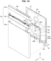
- FIG. 10 is an exploded perspective view illustrating a coupling relationship between the door and the automatic detergent dispenser of the dishwasher according to an embodiment
- FIG. 11 is a perspective view illustrating the automatic detergent dispenser of the dishwasher according to an embodiment
- FIG. 12 is a view illustrating a state in which some components of the automatic detergent dispenser of the dishwasher according to an embodiment are removed
- FIG. 13 is a side cross-sectional view taken along a line A-A' of FIG. 11
- FIG. 14 is an enlarged view of a portion B of FIG. 13 .
- the door 20 may include the outer surface 22 forming the exterior of the dishwasher 1 together with the main body 10, and the inner surface 21 facing the inside of the tub 12 when the door 20 closes the tub 12.
- the door 20 may include an outer frame 22 forming the outer surface 22 of the door 20.
- the door 20 may include an inner frame 21 forming the inner surface 21 of the door 20.
- the outer frame 22 may include a first outer frame member 22a, a second outer frame member 22b, and a handle member 22c disposed between the first outer frame member 22a and the second outer frame member 22b.
- the first outer frame member 22a, the second outer frame member 22b, and the handle member 22c may be coupled to each other to form the front exterior of the door 20.
- the first outer frame member 22a may form an upper portion of the outer frame 22.
- the second outer frame member 22b may form a lower portion of the outer frame 22.
- the handle member 22c may be formed to be gripped by a user when the user opens and closes the door 20.
- the handle member 22c may include a shape inclined with respect to the first outer frame member 22a or the second outer frame member 22b and thus a user can easily grip the handle member 22c.
- the outer frame 22 may include a display 22d.
- the display 22d may display information about the state of the dishwasher 1 (e.g., operating state and operating time of the dishwasher 1, and remaining amount of solid detergent loaded in the automatic detergent dispenser 1000, etc.) to a user.
- the display 22d may be provided to receive information for controlling the dishwasher 1 from a user.
- the display 22d may be configured to provide a user interface (UI).
- UI user interface
- a manipulator not shown configured to receive information for controlling the dishwasher 1 from a user may be arranged in the outer frame 22.
- FIG. 10 illustrates an example in which the display 22d is arranged on the upper surface of the first outer frame member 22a in the third direction Z, but is not limited thereto.
- the display 22d may be arranged on the front surface of the first outer frame member 22a, or the second outer frame member 22b, or the handle member 22c.
- Various electronic components such as a main control device (not shown) configured to control the operation of the dishwasher 1 may be arranged inside the door 20.
- electronic components such as the main control device may be disposed inside the outer frame 22.
- the configuration of the outer frame 22 is not limited thereto.
- the outer frame 22 may be formed as the first outer frame member 22a, the second outer frame member 22b, and the handle member 22c are integrally formed with each other.
- the outer frame 22 may be formed as the first outer frame member 22a and the second outer frame member 22b are integrally formed with each other.
- a handle formed to be gripped by a user for opening the door 20 may be arranged in the first and second outer frame members 22a and 22b.
- the inner frame 21 may be coupled to the outer frame 22. Particularly, the inner frame 21 may be coupled to the outer frame 22 in a direction toward the tub 12 with respect to the outer frame 22 when the door 20 is in the first position 20A. That is, the inner frame 21 may be disposed rearward with respect to the outer frame 22 in the first direction X and coupled to the outer frame 22 when the door 20 is in the first position 20A.
- the outer frame 22 and the inner frame 21 may be coupled to each other by various methods such as the screw fastening.
- the outer frame 22 may include a front surface facing forward in the first direction X, both side surfaces facing the second direction Y, respectively, and an upper surface facing upward in the third direction Z when the door 20 is in the first position 20A.
- the both side surfaces of the outer frame 22 may extend from the front surface of the outer frame 22 toward the inner frame 21.
- the both side surfaces of the outer frame 22 may extend from both ends of the front surface of the outer frame 22 in the second direction Y to the rear side in the first direction X.
- the upper surface of the outer frame 22 may extend from an upper end of the front surface of the outer frame 22 in the third direction Z toward the inner frame 21.
- the upper surface of the outer frame 22 may extend from an upper end of the front surface of the outer frame 22 in the third direction Z to the rear side in the first direction X.
- the inner frame 21 may be formed to include a substantially flat plate shape. When the door 20 is in the first position 20A, the inner frame 21 may be formed to face the first direction X. The inner frame 21 may be formed in parallel to the front surface of the outer frame 22.
- the inner frame 21 may be coupled to a rear portion of the upper surface of the outer frame 22 in the first direction X and a rear portion of the both side surfaces of the outer frame 22 in the first direction X, respectively.
- outer frame 22 and the inner frame 21 may each include various shapes and may be coupled to each other by various configurations.
- the inner frame 21 may include a rear surface facing the rear side in the first direction X, both side surfaces facing the second direction Y, and an upper surface facing the upper side in the third directions Z when the door 20 is in the first position 20A.
- the both side surfaces of the inner frame 21 may extend from the rear surface of the inner frame 21 toward the outer frame 22.
- the both side surfaces of the inner frame 21 may extend from both ends of the rear surface of the inner frame 22 in the second direction Y toward the front side in the first direction.
- the upper surface of the inner frame 21 may extend from an upper end of the rear surface of the inner frame 21 in the third direction Z toward the outer frame 22.
- the upper surface of the inner frame 21 may extend from the upper end of the rear surface of the inner frame 21 in the third direction Z to the front side in the first direction X.
- the outer frame 21 may be formed to include a substantially flat plate shape.
- the outer frame 22 may be formed to face the first direction X.
- the outer frame 22 may be formed in parallel to the rear surface of the inner frame 21.
- the outer frame 22 may be coupled to a front portion of the upper surface of the inner frame 21 in the first direction X and a front portion of the both side surfaces of the inner frame 21 in the first direction X, respectively.
- an inner space I (refer to FIG. 19 ) may be formed between the outer frame 22 and the inner frame 21 coupled to each other.
- the inner space I may have various shapes or sizes according to the shape and size of the outer frame 22 and the inner frame 21 or a component arranged and mounted on the door 20.
- the outer frame 22 and the inner frame 21 may be formed to have sizes corresponding to each other. However, this does not mean that the outer frame 22 and the inner frame 21 have the same size, and the size of the outer frame 22 and the inner frame 21 may vary depending on the coupling relationship between the outer frame 22 and the inner frame 21, the coupling relationship between the door 20 and the main body 10, and the like.
- the upper end of the outer frame 22 and the upper end of the inner frame 21 may be provided with little or no step difference.
- a step difference may be generated between the lower end of the outer frame 22 and the lower end of the inner frame 21, and particularly, a step difference between the lower ends thereof may be greater than a step difference between the upper ends thereof.
- the automatic detergent dispenser 1000 may be coupled to the inner frame 21.
- the inner frame 21 may include an automatic detergent dispenser coupler 21a formed to allow the automatic detergent dispenser 1000 to be coupled thereto.
- the housing 1100 of the automatic detergent dispenser 1000 may be coupled to the automatic detergent dispenser coupler 21a.
- the automatic detergent dispenser 1000 coupled to the automatic detergent dispenser coupler 21a may be arranged to allow the first housing 1110 to face the front side in the first direction X and to allow the second housing 1120 to face the rear side in the first direction X.
- the first housing 1110 may be disposed to face the outer frame 22 and the second housing 1120 may be disposed to face the tub 12.
- the first housing 1110 and the second housing 1120 may be coupled to each other, and the second housing 1120 may be disposed on a side facing the tub 12 with respect to the first housing 1110.
- the storage compartment cover 1140 and the inlet cover 1150 may be disposed to face the rear side in the first direction X.
- the storage compartment cover 1140 and the inlet cover 1150 may be disposed to face the tub 12.
- the automatic detergent dispenser coupler 21a may be formed in an opening shape. Particularly the automatic detergent dispenser coupler 21a may include an opening shape penetrating the inner frame 21. The automatic detergent dispenser 1000 may be inserted or pass through the automatic detergent dispenser coupler 21a and coupled to the inner frame 21.
- the configuration of the door 20 described above is only an example of the door of the dishwasher according to the disclosure, and the disclosure is not limited thereto.
- the automatic detergent dispenser 1000 may include an air discharge guide 1114 provided to guide air discharged through the discharge hole 1610 to the outside of the discharge hole cover 1113.
- the housing 1100 may include the air discharge guide 1114 and the air discharge guide 1114 may be provided in the first housing 1110.
- the air discharge guide 1114 may guide the air to flow to the outside of the discharge hole cover 1113. Accordingly, the air discharged from the discharge hole 1610 may be easily introduced into the inner space I despite of the discharge hole cover 1113.
- the automatic detergent dispenser 1000 may include the driver configured to drive the automatic detergent dispenser 1000 to allow one of the plurality of solid detergents loaded in the storage compartment 1200 to be input into the tub 12.
- the driver may include the driving motor 1320 of the ejector 1300, the seating member door driver 1470 of the seating member 1400, and the like.
- the driver may be disposed inside the housing 1100.
- At least a portion of the wire W may be disposed along the discharge duct 1160.
- the wire W may be disposed along the discharge duct 1160 within a range, which is required by the design to connect the control device 1900 to the driver, according to the arrangement of the control device 1900 or the driver.
- control device 1900 may be disposed outside the inner space formed by the first housing 1110 and the second housing 1120.
- the control device 1900 may be disposed on the control device seating member 1111. In this case, it is easy to protect the control device 1900 from moisture of the inner space of the housing 1100, and to effectively prevent damage to the control device 1900.
- the driver or the sensor of the automatic detergent dispenser 1000 may be disposed in the inner side with respect to the discharge hole 1160, and the control device 1900 may be disposed in the outside with respect to the discharge hole 1160.
- the wire W may be provided to penetrate the discharge hole 1610.
- the wire W may not penetrate the discharge hole 1160.
- the control device 1900 may be disposed in the inner space formed by the first housing 1110 and the second housing 1120, or the control device 1900 may be disposed inside the discharge duct 1600. In this case, the wire W connecting the control device 1900 to the driver or the sensor may not penetrate the discharge hole 1160.
- the wire W may penetrate other hole (not shown) other than the discharge hole 1610, and then connect components such as the control device 1900 and the driver.
- the wire W is disposed along the discharge duct 1600 and further penetrates the discharge hole 1610 and is connected to the control device 1900, it is possible to more simplify the configuration of the automatic detergent dispenser 1000 such as the housing 1100.
- the housing 1100 may include the control device cover 1112 covering the control device 1900.
- the control device cover 1112 may cover a portion of the wire W together.
- control device cover 1112 may cover the control device 1900 from the front in the first direction X. Based on when the door 20 is in the first position 20A, the control device cover 1112 may cover a portion of the wire W from the front in the first direction X.
- the control device cover 1112 may cover the discharge hole 1610.
- the control device cover 1112 may cover the discharge hole 1610, the control device 1900, and a portion of the wire W that passes through the discharge hole 1610 and then connected to the control device 1900.
- the control device cover 1112 may be integrally provided with the discharge hole cover 1113. Accordingly, all of the above-described characteristics of the discharge hole cover 1113 may be applied to the control device cover 1112.
- control device cover 1112 may include a cover portion spaced apart from the discharge hole 1610 to cover the discharge hole 1610.
- the cover portion of the control device cover 1112 may be spaced apart from the discharge hole 1610 by the cover spacer 1115 and may cover the discharge hole 1610.
- the air discharge guide 1114 may be provided to guide the air discharged through the discharge hole 1610 to the outside of the control device cover 1112.
- the control device cover 1112 may be detachably coupled to the discharge hole 1610, and may be hooked to the discharge hole 1610 by the hook 1113b. A description thereof is described above with respect to the discharge hole cover 1113, and thus it will be omitted.
- control device cover 1112 may be provided separately from the discharge hole cover 1113.
- control device cover 1112 may cover the control device 1900 or a portion of the wire W connected to the control device 1900 and adjacent to the control device 1900, but may not cover the discharge hole 1610.
- the discharge hole 1610 may be covered by the discharge hole cover 1113 that is separated from the control device cover 1112.
- a part of the wire W disposed between the control device cover 1112 and the discharge hole cover 1113 may be exposed to the outside.
- a separate cover provided to connect the control device cover 1112 and the discharge hole cover 1113 may be disposed between the control device cover 1112 and the discharge hole cover 1113, and thus a portion of the wire W arranged between the control device cover 1112 and the discharge hole cover 1113 may be covered together.
- the wire W may be guided by a plurality of wire guides 1160a, 1160b, and 1160c.
- a first wire guide 1160a may guide a portion of the wire W disposed between the discharge hole 1610 and the driver or sensor.
- the first wire guide 1160a may be disposed in the inner space formed by the first housing 1110 and the second housing 1120 to guide a portion of the wire W.
- at least a portion of the first wire guide 1160a may be provided inside the discharge duct 1600.
- at least a portion of the first wire guide 1160a may be provided in the intermediate housing 1130.
- a second wire guide 1160b may guide a portion of the wire W disposed between the discharge hole 1610 and the control device 1900.
- the second wire guide 1160b may be covered by the control device cover 1112.
- a third wire guide 1160c may be a part of the wire W connected to the control device 1900, and may guide a part of the wire W disposed outside the control device cover 1112.
- the third wire guide 1160c may guide a portion of the wire W provided to electrically connect the main control device (not shown) of the dishwasher 1 and the control device 1900 of the automatic detergent dispenser 1000.
- wire guides 1160a, 1160b, and 1160c described above are only examples of a configuration for guiding or supporting the wire W, and the disclosure is not limited thereto.
- the wire W may be configured to electrically connect some of components such as the driver, the sensor, the control device 1900 of the automatic detergent dispenser 1000, or the main control device of the dishwasher 1.
- components such as the driver, the sensor, the control device 1900 of the automatic detergent dispenser 1000 described above, or the main control device of the dishwasher 1 may not be electrically connected to each other by wires, but may be configured to transmit and receive signals to each other through a wireless communication. That is, the wire W shown in FIGS. 10 to 14 may not be provided in the automatic detergent dispenser 1000 of the dishwasher 1.
- Air which is introduced into the housing 1100 from the tub 12 when the inlet 1122 is opened, may be discharged to the outside of the housing 1100 through the storage compartment discharge holes 1200h and 1200h' that are formed separately from the discharge holes 1600 and 1600'.
- the storage compartments 1200 and 1200' may include the storage compartment discharge holes 1200h and 1200h' formed to communicate with the inner space I of the door 20.
- the storage compartment discharge holes 1200h and 1200h' may include a first storage compartment discharge hole 1200h formed in the first storage compartment 1200 and a second storage compartment discharge hole 1200h' formed in the second storage compartment 1200'.
- the first storage compartment discharge hole 1200h will be described in detail, but the following description may be equally applied to the second storage compartment discharge hole 1200h'.
- the first storage compartment discharge hole 1200h will be referred to as the storage compartment discharge hole 1200h.
- the storage compartment discharge hole 1200h may be located on one side of the storage compartment 1200 in the direction toward the outer frame 22 along the first direction X.
- the storage compartment discharge hole 1200h may be formed on one surface, which is at a side toward the outer frame 22, of the storage compartment 1200.
- the storage compartment discharge hole 1200h may be formed on one side of the storage compartment 1200 in a direction in which a plurality of solid detergents is stacked. In other words, the storage compartment discharge hole 1200h may be formed on one side of the storage compartment 1200 in the third direction Z when the door 20 is in the first position 20A.
- An air flow path P disposed between the inlet 1122 and the storage compartment discharge hole 1200h may be formed inside the housing 1100. That is, the automatic detergent dispenser 1000 may include the air flow path P formed from the inlet 1122 toward the storage compartment discharge hole 1200h.
- the automatic detergent dispenser 1000 may include the storage compartment discharge holes 1200h and 1200h', but not include the discharge holes 1610 and 1610' which are formed separately from the storage compartment discharge holes 1200h and 1200h'.
- the storage compartment discharge holes 1200h and 1200h' may perform the function of the discharge holes 1610 and 1610' according to the above-described embodiment.
- the storage compartments 1200 and 1200' may perform the functions of the discharge ducts 1600 and 1600' according to the above-described embodiment.
- the discharge ducts 1600 and 1600' and the discharge holes 1610 and 1610' are formed separately from the storage compartments 1200 and 1200' and the storage compartment discharge holes 1200h and 1200h' as in the embodiment shown in FIGS. 10 to 14 , it is possible to guide at least a portion of air, which is introduced into the inlet 1122, toward the discharge ducts 1600 and 1600'. Accordingly, it is possible to more effectively prevent damage and quality degradation of the solid detergent loaded into the storage compartments 1200 and 1200'.
- control device cover 1112 covers the control device 1900 in the first direction X and the discharge hole cover 1113 covers the discharge hole 1610 in the first direction X, there is still the above-mentioned difficulty when the introduced wash water is not sufficiently drained.
- FIG. 17 is a view illustrating a state in which the automatic detergent dispenser is separated from an inner frame of the dishwasher according to an embodiment
- FIG. 18 is an enlarged cross-sectional view taken along a line C-C' of FIG. 17 .
- the door 20 may include the inner frame 21 including the opening.
- the inner frame 21 may include the automatic detergent dispenser coupler 21a having an opening shape.
- the opening of the automatic detergent dispenser coupler 21a may be formed to penetrate the inner frame 21 in the first direction X.
- the housing 1100 of the automatic detergent dispenser 1000 may pass through the opening of the automatic detergent dispenser coupler 21a and be coupled to the inner frame 21. Particularly, the housing 1100 may pass through the inner frame 21 through the opening. At least a portion of the housing 1100 may be disposed in the inner space I of the door 20, and at least another portion of the housing 1100 may be placed on the side of the tub 12.
- the automatic detergent dispenser coupler 21a may further include a bending member 21aa that is bent and extends from the edge of the opening to the outer frame 22.
- the bending member 21aa may be bent from the edge of the opening of the automatic detergent dispenser coupler 21a and extend forward in the first direction X.
- the bending member 21aa may be provided along the edge of the opening of the automatic detergent dispenser coupler 21a.
- the bending member 21aa may be formed by the press working which presses and bends an edge portion of the opening of the automatic detergent dispenser coupler 21a.
- the bending member 21aa may be formed by various manufacturing methods.
- a contact area between the automatic detergent dispenser coupler 21a and the automatic detergent dispenser 1000 may increase.
- the contact area between the automatic detergent dispenser coupler 21a and the automatic detergent dispenser 1000 may increase along the first direction X by the bending member 21aa.
- the bending member 21aa When the door 20 is in the first position 20A, the bending member 21aa may be provided to allow water, which is introduced from the tub 12 to the opening of the automatic detergent dispenser coupler 21a, to be drained to the lower side of the door 20.
- the bending member 21aa may be provided to allow water, which is introduced from the tub 12 into the opening of the automatic detergent dispenser coupler 21a, to be drained downward along the bending member 21aa.
- the bending member 21aa may form a surface extending in the first direction X from the edge of the opening of the automatic detergent dispenser coupler 21a, and water, which is introduced from the tub 12 to the opening, may be drained downward along the surface of the bending member 21aa.
- FIG. 19 is a side cross-sectional view of the dishwasher according to an embodiment.
- air introduced into the inner space I formed between the inner frame 21 and the outer frame 22 through the discharge hole 1610 may be discharged to the outside of the door 20.
- the air flow path formed to discharge air from the inner space I to the outside of the door 20 may include an upper flow path P1 through which air flows upward with respect to the third direction Z of the door 20 based on when the door 20 is in the first position 20A.
- the upper flow path P1 may be formed to face a gap formed in the upper portion of the door 20 from the inner space I, for example, a gap formed in the locking device installation hole 21d. At least portion of the air in the inner space I may be discharged to the outside of the upper side of the door 20 through the upper flow path P1.
- the air flow path formed to discharge air from the inner space I to the outside of the door 20 may include a lower flow path P2 through which air flows downward with respect to the third direction Z of the door 20 based on when the door 20 is in the first position 20A.
- the inner space I may be in communication with the tub 12 when the door 20 is in the first position 20A, and the lower flow path P2 may be formed to face the lower portion of the tub 12 from the inner space I. At least portion of the air in the inner space I may be introduced into the lower portion of the tub 12 through the lower flow path P2.
- the air of the inner space I may be discharged to the outside of the door 20 along various flow paths through the gap formed in the outer frame 22 or the inner frame 21 or the gap formed between the outer frame 22 and the inner frame 21.
- control device 1900 may control the automatic detergent dispenser 1000 to allow the second ejector 1300' to be driven.
- the holder 1500 may be provided in a shape that is contracted in the second direction Y when the support wall 1271 is moved in a direction away from the right surface 1230 or the left surface 1240.
- first adjusting member 1270 and the second adjusting member 1270' may be disposed on the right surface 1230 of the first storage compartment 1200 and the right surface 1230' of the second storage compartment 1200', respectively.
- the adjusting member 1270 may be provided in only one of the first storage compartment 1200 and the second storage compartment 1200'.
- the adjusting member 1270 of the first storage compartment 1200 may be disposed adjacent to the left surface 1240 to allow the width L1 of the first storage compartment 1200 to correspond to the width d1 of the general solid detergent D, and the adjusting member 1270' of the second storage compartment 1200' may be moved in the second direction Y from the right surface 1230' to allow the width L6 of the second storage compartment 1200' to correspond to the width d1" of some solid detergent D".
- a user can load the general solid detergent D into the first storage compartment 1200 and load some solid detergent D" into the second storage compartment 1200'.
- the storage compartment 1200 may include an adjusting member detection sensor configured to detect a position of each of the support walls 1271 and 1271'.
- the adjusting member detection sensor may detect a position in which the support wall 1271 of the first storage compartment 1200 and the support wall 1271' of the second storage compartment 1200' are disposed, and the control device 1900 may be configured to recognize the type of solid detergent loaded in the first storage compartment 1200 and the type of the solid detergent loaded in the second storage compartment 1200' based on the detected value.
- the adjusting member detection sensor may measure a distance to a position of each of the support walls 1271 and 1271', or detect a distance to a position of each of the support walls 1271 and 1271' by detecting a distance in which each of the movers 1272 and 1272' is moved, extended or contracted.
- a user can input information about the washing mode of the dishwasher 1 through the inputter of the dishwasher 1 or a mobile device to allow the dishwasher 1 to selectively perform one of the normal washing mode and the small amount washing mode.
- the control device 1900 may control the automatic detergent dispenser 1000 to allow the first ejector 1300 or the second ejector 1300' to be driven based on the user input obtained from the main control device, and a value sensed by the adjusting member detection sensor.
- control device 1900 may control the automatic detergent dispenser 1000 to allow the first ejector 1300 to be driven.
- controller 1900 may control the automatic detergent dispenser 1000 to allow the second ejector 1300' to be driven.
Landscapes
- Washing And Drying Of Tableware (AREA)
Applications Claiming Priority (2)
| Application Number | Priority Date | Filing Date | Title |
|---|---|---|---|
| KR1020220146529A KR20240064457A (ko) | 2022-11-04 | 2022-11-04 | 식기세척기 |
| PCT/KR2023/011807 WO2024096271A1 (fr) | 2022-11-04 | 2023-08-10 | Lave-vaisselle |
Publications (2)
| Publication Number | Publication Date |
|---|---|
| EP4582002A1 true EP4582002A1 (fr) | 2025-07-09 |
| EP4582002A4 EP4582002A4 (fr) | 2026-01-07 |
Family
ID=90926727
Family Applications (1)
| Application Number | Title | Priority Date | Filing Date |
|---|---|---|---|
| EP23885968.0A Pending EP4582002A4 (fr) | 2022-11-04 | 2023-08-10 | Lave-vaisselle |
Country Status (3)
| Country | Link |
|---|---|
| US (1) | US12551085B2 (fr) |
| EP (1) | EP4582002A4 (fr) |
| CN (1) | CN120018804A (fr) |
Family Cites Families (28)
| Publication number | Priority date | Publication date | Assignee | Title |
|---|---|---|---|---|
| DE4037367C2 (de) | 1990-11-23 | 1994-03-31 | Bosch Siemens Hausgeraete | Anordnung zum Trocknen von Geschirr in Geschirrspülmaschinen |
| KR19980026613U (ko) | 1996-11-12 | 1998-08-05 | 이영서 | 식기세척기의 세제자동투입장치 |
| KR200313947Y1 (ko) | 2003-02-17 | 2003-05-22 | 이소학 | 수돗물 및 세제 혼합물 절환 공급장치 |
| US7231928B2 (en) | 2003-05-20 | 2007-06-19 | Whirlpool Corporation | Household dishwasher with bulk wash aid dispenser |
| US7275552B2 (en) | 2003-12-13 | 2007-10-02 | Whirlpool Corporation | Dishwasher with bulk wash aid dispenser |
| DE102005062471A1 (de) | 2005-12-27 | 2007-07-12 | BSH Bosch und Siemens Hausgeräte GmbH | Haushalt-Geschirrspülmaschine |
| US20080276969A1 (en) | 2007-05-07 | 2008-11-13 | Whirlpool Corporation | Appliance with unique locking receptacles |
| US20090090401A1 (en) | 2007-10-05 | 2009-04-09 | Whirlpool Corporation | Appliance with Multiple Source Wash Aid Pump |
| CN102088893A (zh) | 2008-07-15 | 2011-06-08 | 汉高股份有限及两合公司 | 用于洗碗机的配量系统 |
| KR20100025359A (ko) | 2008-08-27 | 2010-03-09 | 엘지전자 주식회사 | 세척기기 |
| US9861258B2 (en) | 2013-03-15 | 2018-01-09 | Whirlpool Corporation | Dishwasher |
| ITTO20130562A1 (it) | 2013-07-04 | 2015-01-05 | Eltek Spa | Dispensatore di agenti di lavaggio per macchine di lavaggio domestiche, particolarmente lavastoviglie |
| US9717393B2 (en) | 2014-06-12 | 2017-08-01 | Whirlpool Corporation | Household appliance with bulk unit-dose dispenser |
| WO2016034219A1 (fr) | 2014-09-03 | 2016-03-10 | Arcelik Anonim Sirketi | Distributeur de détergent comportant un dispositif d'éjection de tablette de détergent et lave-vaisselle doté dudit distributeur de détergent |
| JP6788333B2 (ja) | 2015-07-30 | 2020-11-25 | シャープ株式会社 | 洗濯機 |
| GB2557202B (en) * | 2016-11-30 | 2019-05-15 | Reckitt Benckiser Finish Bv | Dosing device and system |
| KR20200000088U (ko) | 2018-07-02 | 2020-01-13 | 경수 예 | 식기세척기 세제 분배기 |
| KR20200000474U (ko) | 2018-08-21 | 2020-03-03 | 경수 예 | 식기세척기의 세제투입장치 |
| US11284776B2 (en) * | 2018-12-22 | 2022-03-29 | Emz-Hanauer Gmbh & Co. Kgaa | Tablet dosing system and water-carrying domestic cleaning apparatus equipped therewith |
| EP3996568A1 (fr) | 2019-07-09 | 2022-05-18 | Reckitt Benckiser (Brands) Limited | Unité de dosage, appareil électroménager à circulation d'eau et procédé |
| WO2021013724A1 (fr) | 2019-07-24 | 2021-01-28 | Reckitt Benckiser (Brands) Limited | Unité de dosage, appareil électroménager à circulation d'eau et procédé |
| EP3769656A1 (fr) | 2019-07-24 | 2021-01-27 | BSH Hausgeräte GmbH | Appareil ménager à circulation d'eau et procédé de fonctionnement d'un appareil ménager à circulation d'eau |
| KR20210000392U (ko) | 2019-08-07 | 2021-02-18 | 채인수 | 식기세척기용 디스펜서의 세제챔버덮개 수동열림 스윗치장치 |
| DE102020128650A1 (de) * | 2020-06-09 | 2021-12-09 | Emz-Hanauer Gmbh & Co. Kgaa | Haushalts-Geschirrspülmaschine und Dosiersystem hierfür |
| KR20220026822A (ko) | 2020-08-26 | 2022-03-07 | 엘지전자 주식회사 | 식기 세척기 |
| KR20220026823A (ko) | 2020-08-26 | 2022-03-07 | 엘지전자 주식회사 | 식기 세척기 |
| KR20220026821A (ko) | 2020-08-26 | 2022-03-07 | 엘지전자 주식회사 | 식기 세척기 및 그제어 방법 |
| DE102021110759A1 (de) | 2020-12-07 | 2022-06-09 | Emz-Hanauer Gmbh & Co. Kgaa | Dosierung eines Feststoff-Reinigungsmittels in einer Haushalts-Geschirrspülmaschine |
-
2023
- 2023-08-10 EP EP23885968.0A patent/EP4582002A4/fr active Pending
- 2023-08-10 CN CN202380072288.0A patent/CN120018804A/zh active Pending
- 2023-12-29 US US18/401,175 patent/US12551085B2/en active Active
Also Published As
| Publication number | Publication date |
|---|---|
| CN120018804A (zh) | 2025-05-16 |
| US12551085B2 (en) | 2026-02-17 |
| US20240148221A1 (en) | 2024-05-09 |
| EP4582002A4 (fr) | 2026-01-07 |
Similar Documents
| Publication | Publication Date | Title |
|---|---|---|
| EP4582002A1 (fr) | Lave-vaisselle | |
| EP4582005A1 (fr) | Lave-vaisselle | |
| US20240148227A1 (en) | Dishwasher | |
| EP4566509A1 (fr) | Lave-vaisselle | |
| US20250241508A1 (en) | Dish washer | |
| EP4582003A1 (fr) | Lave-vaisselle | |
| US20250228425A1 (en) | Dishwasher | |
| EP4582001A1 (fr) | Lave-vaisselle | |
| CN113226146B (zh) | 餐具清洗机 | |
| EP4582000A1 (fr) | Lave-vaisselle et son procédé de commande | |
| US12582280B2 (en) | Dishwasher and control method thereof | |
| KR20240064457A (ko) | 식기세척기 | |
| EP3682787B1 (fr) | Lave-vaisselle | |
| KR20240064463A (ko) | 식기세척기 | |
| KR20240064456A (ko) | 식기세척기 | |
| KR20240064466A (ko) | 식기세척기 | |
| KR20240064455A (ko) | 식기세척기 | |
| US20250228424A1 (en) | Dish washer and control method thereof | |
| KR20240064465A (ko) | 식기세척기 | |
| EP4458245A1 (fr) | Lave-vaisselle | |
| EP4461191A1 (fr) | Ensemble drain et appareil ménager | |
| KR20260035036A (ko) | 식기세척기 | |
| KR20240064464A (ko) | 식기세척기 | |
| KR20240064458A (ko) | 식기세척기 및 그 제어 방법 | |
| KR20250122340A (ko) | 식기세척기 |
Legal Events
| Date | Code | Title | Description |
|---|---|---|---|
| STAA | Information on the status of an ep patent application or granted ep patent |
Free format text: STATUS: THE INTERNATIONAL PUBLICATION HAS BEEN MADE |
|
| PUAI | Public reference made under article 153(3) epc to a published international application that has entered the european phase |
Free format text: ORIGINAL CODE: 0009012 |
|
| STAA | Information on the status of an ep patent application or granted ep patent |
Free format text: STATUS: REQUEST FOR EXAMINATION WAS MADE |
|
| 17P | Request for examination filed |
Effective date: 20250331 |
|
| AK | Designated contracting states |
Kind code of ref document: A1 Designated state(s): AL AT BE BG CH CY CZ DE DK EE ES FI FR GB GR HR HU IE IS IT LI LT LU LV MC ME MK MT NL NO PL PT RO RS SE SI SK SM TR |
|
| A4 | Supplementary search report drawn up and despatched |
Effective date: 20251210 |
|
| RIC1 | Information provided on ipc code assigned before grant |
Ipc: A47L 15/44 20060101AFI20251204BHEP Ipc: A47L 15/48 20060101ALI20251204BHEP Ipc: A47L 15/42 20060101ALI20251204BHEP |
|
| DAV | Request for validation of the european patent (deleted) | ||
| DAX | Request for extension of the european patent (deleted) |