EP4579352A1 - Bilderzeugungsgerät - Google Patents
Bilderzeugungsgerät Download PDFInfo
- Publication number
- EP4579352A1 EP4579352A1 EP24181583.6A EP24181583A EP4579352A1 EP 4579352 A1 EP4579352 A1 EP 4579352A1 EP 24181583 A EP24181583 A EP 24181583A EP 4579352 A1 EP4579352 A1 EP 4579352A1
- Authority
- EP
- European Patent Office
- Prior art keywords
- photoreceptor
- image forming
- forming apparatus
- charger
- unit
- Prior art date
- Legal status (The legal status is an assumption and is not a legal conclusion. Google has not performed a legal analysis and makes no representation as to the accuracy of the status listed.)
- Pending
Links
Images


Classifications
-
- G—PHYSICS
- G03—PHOTOGRAPHY; CINEMATOGRAPHY; ANALOGOUS TECHNIQUES USING WAVES OTHER THAN OPTICAL WAVES; ELECTROGRAPHY; HOLOGRAPHY
- G03G—ELECTROGRAPHY; ELECTROPHOTOGRAPHY; MAGNETOGRAPHY
- G03G21/00—Arrangements not provided for by groups G03G13/00 - G03G19/00, e.g. cleaning, elimination of residual charge
- G03G21/0005—Arrangements not provided for by groups G03G13/00 - G03G19/00, e.g. cleaning, elimination of residual charge for removing solid developer or debris from the electrographic recording medium
-
- G—PHYSICS
- G03—PHOTOGRAPHY; CINEMATOGRAPHY; ANALOGOUS TECHNIQUES USING WAVES OTHER THAN OPTICAL WAVES; ELECTROGRAPHY; HOLOGRAPHY
- G03G—ELECTROGRAPHY; ELECTROPHOTOGRAPHY; MAGNETOGRAPHY
- G03G15/00—Apparatus for electrographic processes using a charge pattern
- G03G15/50—Machine control of apparatus for electrographic processes using a charge pattern, e.g. regulating differents parts of the machine, multimode copiers, microprocessor control
- G03G15/5008—Driving control for rotary photosensitive medium, e.g. speed control, stop position control
-
- G—PHYSICS
- G03—PHOTOGRAPHY; CINEMATOGRAPHY; ANALOGOUS TECHNIQUES USING WAVES OTHER THAN OPTICAL WAVES; ELECTROGRAPHY; HOLOGRAPHY
- G03G—ELECTROGRAPHY; ELECTROPHOTOGRAPHY; MAGNETOGRAPHY
- G03G15/00—Apparatus for electrographic processes using a charge pattern
- G03G15/02—Apparatus for electrographic processes using a charge pattern for laying down a uniform charge, e.g. for sensitising; Corona discharge devices
- G03G15/0275—Arrangements for controlling the area of the photoconductor to be charged
-
- G—PHYSICS
- G03—PHOTOGRAPHY; CINEMATOGRAPHY; ANALOGOUS TECHNIQUES USING WAVES OTHER THAN OPTICAL WAVES; ELECTROGRAPHY; HOLOGRAPHY
- G03G—ELECTROGRAPHY; ELECTROPHOTOGRAPHY; MAGNETOGRAPHY
- G03G15/00—Apparatus for electrographic processes using a charge pattern
- G03G15/50—Machine control of apparatus for electrographic processes using a charge pattern, e.g. regulating differents parts of the machine, multimode copiers, microprocessor control
- G03G15/5004—Power supply control, e.g. power-saving mode, automatic power turn-off
-
- G—PHYSICS
- G03—PHOTOGRAPHY; CINEMATOGRAPHY; ANALOGOUS TECHNIQUES USING WAVES OTHER THAN OPTICAL WAVES; ELECTROGRAPHY; HOLOGRAPHY
- G03G—ELECTROGRAPHY; ELECTROPHOTOGRAPHY; MAGNETOGRAPHY
- G03G15/00—Apparatus for electrographic processes using a charge pattern
- G03G15/50—Machine control of apparatus for electrographic processes using a charge pattern, e.g. regulating differents parts of the machine, multimode copiers, microprocessor control
- G03G15/5033—Machine control of apparatus for electrographic processes using a charge pattern, e.g. regulating differents parts of the machine, multimode copiers, microprocessor control by measuring the photoconductor characteristics, e.g. temperature, or the characteristics of an image on the photoconductor
- G03G15/505—Detecting the speed, e.g. for continuous control of recording starting time
-
- G—PHYSICS
- G03—PHOTOGRAPHY; CINEMATOGRAPHY; ANALOGOUS TECHNIQUES USING WAVES OTHER THAN OPTICAL WAVES; ELECTROGRAPHY; HOLOGRAPHY
- G03G—ELECTROGRAPHY; ELECTROPHOTOGRAPHY; MAGNETOGRAPHY
- G03G2215/00—Apparatus for electrophotographic processes
- G03G2215/16—Transferring device, details
- G03G2215/1604—Main transfer electrode
- G03G2215/1623—Transfer belt
-
- G—PHYSICS
- G03—PHOTOGRAPHY; CINEMATOGRAPHY; ANALOGOUS TECHNIQUES USING WAVES OTHER THAN OPTICAL WAVES; ELECTROGRAPHY; HOLOGRAPHY
- G03G—ELECTROGRAPHY; ELECTROPHOTOGRAPHY; MAGNETOGRAPHY
- G03G2221/00—Processes not provided for by group G03G2215/00, e.g. cleaning or residual charge elimination
- G03G2221/0026—Cleaning of foreign matter, e.g. paper powder, from imaging member
- G03G2221/0031—Type of foreign matter
- G03G2221/0042—Paper powder and other dry foreign matter
Definitions
- the present invention relates to an image forming apparatus.
- JP2023-70972A addresses an issue of reducing occurrence of an abnormal image such as a blurred image or a scratchy image.
- a technology for executing a control mode for idly driving a photoreceptor before a start of a printing operation in a case where a time exceeding a predetermined time elapses after a previous printing operation is finished has been disclosed.
- An object of the present invention is to suppress occurrence of an abnormal image, compared to a case where a positional relationship between a photoreceptor and a charger and/or a cleaning unit does not change before printing is started.
- an image forming apparatus including a photoreceptor that holds a toner image to be transferred to a paper sheet, a charger that charges a surface of the photoreceptor, a developer that supplies toner to the surface of the photoreceptor, a cleaning unit that collects toner stuck to the photoreceptor, and a unit that changes a positional relationship between the photoreceptor and the charger and/or a positional relationship between the photoreceptor and the cleaning unit under a predetermined condition after the photoreceptor stops.
- the unit that changes the positional relationship may move the photoreceptor by a predetermined distance on a condition that a predetermined time has elapsed after the photoreceptor stops.
- the unit that changes the positional relationship may rotate the photoreceptor at a speed slower than a speed in a printing state.
- the unit that changes the positional relationship may rotate the photoreceptor and also rotate the developer.
- the image forming apparatus may further include a transfer belt to which the toner image held in the photoreceptor is transferred, in which in moving the photoreceptor by a predetermined distance, the transfer belt is moved to a position separated from the photoreceptor.
- the unit that changes the positional relationship may transition to a mode for suppressing power consumption after the photoreceptor stops, and change the positional relationship between the photoreceptor and the charger and/or the positional relationship between the cleaning unit and the photoreceptor under the predetermined condition.
- the predetermined condition may be a condition determined for suppressing a change in the photoreceptor caused by discharge from the charger and/or a change in the photoreceptor caused by a volatile component from waste toner in the cleaning unit.
- an image forming apparatus including a photoreceptor that holds a toner image to be transferred to a paper sheet, a charger that charges a surface of the photoreceptor, a developer that supplies toner to the surface of the photoreceptor, a cleaning unit that collects toner stuck to the photoreceptor, and a suppressing unit that suppresses an increase in a residual potential on the surface of the photoreceptor or a decrease in electrical resistance caused by sticking of a discharge product of the charger to the surface of the photoreceptor after the photoreceptor stops.
- the suppressing unit may rotate the photoreceptor under a predetermined condition after the photoreceptor stops.
- the predetermined condition may be gradual rotation of the photoreceptor.
- occurrence of an abnormal image can be suppressed, compared to a case where the positional relationship between the photoreceptor and the charger and/or the cleaning unit does not change before printing starts.
- the positional relationship can be changed under a condition in which the occurrence of the abnormal image can be suppressed.
- a distance in which the photoreceptor is moved can be accurately controlled, compared to a case where the photoreceptor is not rotated at a speed slower than the speed in the printing state.
- damage to the photoreceptor caused by friction between the photoreceptor and the developer can be suppressed, compared to a case where the developer is not rotated.
- damage to the photoreceptor caused by friction between the photoreceptor and the transfer belt can be suppressed.
- the occurrence of the abnormal image can be suppressed while the power consumption is suppressed.
- the occurrence of the abnormal image caused by an event occurring between the photoreceptor and the charger and/or the cleaning unit can be suppressed.
- the image forming apparatus in which the occurrence of the abnormal image caused by an event occurring between the photoreceptor and the charger and/or the cleaning unit is suppressed can be provided.
- a suppressing effect of the suppressing unit can be easily obtained.
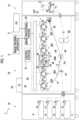
- Fig. 1 is a diagram for describing an image forming apparatus 1 in the present exemplary embodiment.
- the image forming apparatus 1 includes a paper feeding unit 1A, a printing unit 1B, and a paper discharging unit 1C.
- the paper feeding unit 1A includes a first paper sheet accommodation portion 11 to a fourth paper sheet accommodation portion 14 that accommodate a paper sheet P as an example of a recording medium.
- feeding rolls 15 to 18 that are provided to correspond to the first paper sheet accommodation portion 11 to the fourth paper sheet accommodation portion 14, respectively, and that feed the paper sheet P accommodated in each paper sheet accommodation portion to a transport path connected to the printing unit 1B are provided in the paper feeding unit 1A.
- the printing unit 1B includes an image forming portion 20 that forms an image on the paper sheet P.
- a control portion 21 that controls each part of the image forming apparatus 1 is provided in the printing unit 1B.
- the exposure of the photoreceptor 31 by the exposure device 26 is not limited to use of laser light.
- a light source such as a light emitting diode (LED) may be provided for each image forming unit 30, and the exposure of the photoreceptor 31 may be performed using light emitted from the light source.
- LED light emitting diode
- Each image forming unit 30 has the same configuration except for the toner accommodated in the developer 33.
- the image forming units 30Y, 30M, 30C, and 30K form toner images of yellow (Y), magenta (M), cyan (C), and black (K), respectively.
- the image forming units 30T and 30P form toner images using white toner, toner corresponding to a corporate color, formable toner for braille, fluorescent color toner, toner that improves glossiness, and the like.
- the image forming units 30T and 30P form toner images using toner of special colors.
- a belt cleaner 45 that removes toner or the like on a surface of the intermediate transfer belt 41, and a fixer 80 that fixes the secondarily transferred image on the paper sheet P are provided in the image forming portion 20.
- the image forming portion 20 performs an image forming operation based on a control signal from the control portion 21.
- the charger 32 charges the surface of the photoreceptor 31, and then the exposure device 26 irradiates the photoreceptor 31 with laser light that is modulated using the image data obtained from the image processing portion 22. Accordingly, an electrostatic latent image is formed on the photoreceptor 31.
- the formed electrostatic latent image is developed by the developer 33, and a toner image of magenta is formed on the photoreceptor 31.
- Each color toner image formed in each image forming unit 30 is sequentially electrostatically transferred to the intermediate transfer belt 41 rotating in a direction of arrow C in Fig. 1 by the primary transfer roll 42, and superimposed toner images are formed on the intermediate transfer belt 41.
- the paper sheet P is supplied to the secondary transfer portion P2 from the resist roll 74 in accordance with a time of the transport.
- Fig. 2 is an enlarged view of the image forming unit 30.
- the rotation mechanism 60 and a separation mechanism 61 in the present exemplary embodiment will be described using Fig. 2 .
- the rotation mechanism 60 and the separation mechanism 61 are controlled by the control portion 21 described in Fig. 1 .
- the image forming apparatus 1 includes the rotation mechanism 60 that rotates the photoreceptor 31.
- a case where the rotation mechanism 60 rotates the photoreceptor 31 in the direction of A in Fig. 2 includes a case where the image forming apparatus 1 described in Fig. 1 performs the image forming operation, and a case where the image forming apparatus 1 performs the image forming operation under a predetermined condition after the rotation of the photoreceptor 31 stops.
- the predetermined condition include an elapse of a predetermined time after the photoreceptor stops.
- the predetermined time is, for example, a time determined for suppressing a change in the photoreceptor 31 caused by a volatile component from the waste toner in the cleaning unit 34 and is, for example, two hours.
- another example of the predetermined time is, for example, a time determined for suppressing a change in the photoreceptor 31 caused by discharge from the charger 32 and is, for example, five hours.
- the predetermined time changes depending on situations of the photoreceptor 31, the cleaning unit 34, the charger 32, and the like.
- the rotation mechanism 60 rotates the photoreceptor 31 in order to suppress the change in the photoreceptor 31 caused by the volatile component from the waste toner in the cleaning unit 34 or to suppress the change in the photoreceptor 31 caused by the discharge from the charger 32.
- the photoreceptor 31 is rotated for a predetermined time under both conditions for suppressing the changes. That is, a positional relationship between the photoreceptor 31 and the charger 32 and/or a positional relationship between the photoreceptor 31 and the cleaning unit 34 is changed under the predetermined condition after the photoreceptor 31 stops.
- the change in the photoreceptor 31 caused by the volatile component from the waste toner in the cleaning unit 34 may be referred to as a cleaning unit-derived defect.
- the change in the photoreceptor 31 caused by the discharge from the charger 32 may be referred to as a charger-derived defect.
- the rotation mechanism 60 rotates the photoreceptor 31 one round in the direction of A. Meanwhile, in a case where the predetermined time has elapsed after the photoreceptor 31 stops, the rotation mechanism 60 rotates the photoreceptor 31 by a predetermined distance or longer. Rotating the photoreceptor 31 by the predetermined distance or longer changes the positional relationship between the photoreceptor 31 and the cleaning unit 34 and the positional relationship between the photoreceptor 31 and the charger 32.
- the predetermined distance is, for example, a distance of an arc of a region a1 surrounded by the cleaning unit 34 in a region of the surface of the photoreceptor 31.
- the predetermined distance is, for example, a distance of an arc of a region a2 surrounded by the charger 32 in the region of the surface of the photoreceptor 31. That is, the rotation mechanism 60 rotates the photoreceptor 31 by the distance of the arc of the region a1 or longer or by the distance of the arc of the region a2 or longer.
- the region a1 after movement is moved to a region that does not overlap with the region a1 before movement. Furthermore, the region surrounded by the cleaning unit 34 is changed to a region different from the region a1.
- the region a2 after movement is moved to a region that does not overlap with the region a2 before movement. Furthermore, the region surrounded by the charger 32 is changed to a region different from the region a2.
- the photoreceptor 31 may be rotated in a direction opposite to the direction of A in order to change a positional relationship between the cleaning unit 34 and the charger 32, and the region a1 and the region a2.
- the cleaning unit 34 may be moved instead of moving the photoreceptor 31.
- the cleaning unit-derived defect and/or the charger-derived defect is eliminated by changing the predetermined time and the predetermined distance depending on various situations such as a difference in a type or a structure and a difference in a relationship among the cleaning unit 34, the charger 32, and the photoreceptor 31.
- the predetermined condition is set to eliminate each defect after the photoreceptor 31 stops.
- the predetermined condition for example, the time determined for eliminating each defect is set as the predetermined time, and a distance longer than or equal to the distance of a length of the arc of each surrounded region is set as the predetermined distance.
- the time determined for eliminating the cleaning unit-derived defect is set as the predetermined time, and a distance longer than or equal to the distance of the arc of the region a1 surrounded by the cleaning unit 34 is set as the predetermined distance.
- the time determined for eliminating the charger-derived defect is set as the predetermined time, and a distance longer than or equal to the distance of the arc of the region a2 surrounded by the charger 32 is set as the predetermined distance.
- the predetermined time and the predetermined distance are set by comparing lengths of the time determined for suppressing each derived defect and magnitudes of the length of the arc of each surrounded region. For example, a case where the time for suppressing the charger-derived defect is shorter than the time for suppressing the cleaning unit-derived defect and where the length of the arc of the region a2 surrounded by the charger 32 is longer than the length of the arc of the region a1 surrounded by the cleaning unit 34 is assumed.
- the time determined for suppressing the charger-derived defect is set as the predetermined time, and a distance longer than or equal to the distance of the arc of the region a2 surrounded by the charger 32 is set as the predetermined distance, in order to eliminate both of the cleaning unit-derived defect and the charger-derived defect.
- a case where the time for suppressing the charger-derived defect is longer than the time for suppressing the cleaning unit-derived defect and where the length of the arc of the region a2 surrounded by the charger 32 is longer than the length of the arc of the region a1 surrounded by the cleaning unit 34 is assumed. That is, a case of time for suppressing the cleaning unit-derived defect ⁇ time for suppressing the charger-derived defect and length of the arc of the region a1 ⁇ length of the arc of the region a2 is assumed. Furthermore, an assumption that the region a2 after movement is moved to a region not overlapping with the region a2 before movement by moving the length of the arc of the region a1 n times is assumed.
- the predetermined time is set on a condition that a time required for movement performed once is shorter than or equal to the time determined for suppressing the cleaning unit-derived defect and that a time required for performing movement n times is shorter than or equal to the time determined for suppressing the charger-derived defect.
- the predetermined distance is set on a condition of a distance longer than or equal to the distance of the arc of the region a1 surrounded by the cleaning unit 34.
- the predetermined time can also be set on a condition of the time determined for suppressing the cleaning unit-derived defect, and the predetermined distance can also be set on a condition of a distance longer than or equal to the distance of the arc of the region a2 surrounded by the charger 32, without taking into consideration the movement of the length of the arc of the region a1 performed n times.
- the positional relationship between the photoreceptor 31 and the developer 33 is changed by rotating the photoreceptor 31 by the predetermined distance via the rotation mechanism 60 after the predetermined time elapses from the stoppage of the photoreceptor 31.
- the predetermined time is a time determined for suppressing a change in the photoreceptor caused by a volatile component from the toner in the developer 33.
- the predetermined distance corresponds to a region surrounded by the developer 33 in the region of the surface of the photoreceptor 31.
- the developer 33 may be additionally taken into consideration in setting the predetermined time and the predetermined distance as described above.
- the developer 33 includes a developing roll 33a that is in contact with the photoreceptor 31.
- the rotation mechanism 60 also rotates the developing roll 33a in a direction of arrow B in rotating the photoreceptor 31. Accordingly, friction between the developer 33 and the photoreceptor 31 may be reduced.
- the image forming apparatus 1 includes the separation mechanism 61 that adjusts a state of contact between the intermediate transfer belt 41 and the photoreceptor 31.
- the separation mechanism 61 brings the intermediate transfer belt 41 into contact with the photoreceptor 31 by pushing the primary transfer roll 42 and releases the contact between the intermediate transfer belt 41 and the photoreceptor 31 by pulling the primary transfer roll 42. That is, the separation mechanism 61 moves the intermediate transfer belt 41 to a position separated from the photoreceptor 31.
- the separation mechanism 61 is configured by combining a motor, a solenoid, a spring structure, and the like.
- Fig. 3 is a timing chart illustrating the rotation control of the photoreceptor 31.
- an upper part illustrates the rotation control of the photoreceptor 31 in a "normal mode”
- a lower part illustrates the rotation control of the photoreceptor 31 in a "power saving mode”.
- T0 to T9 illustrated in Fig. 3 indicate time points for description.
- Fig. 4 is a flowchart of the rotation control of the photoreceptor 31 in the normal mode in the present exemplary embodiment
- Fig. 5 is a flowchart of the rotation control of the photoreceptor 31 in the power saving mode in the present exemplary embodiment.
- the power saving mode is a mode in which power consumption of the image forming apparatus 1 is reduced below power consumption of the image forming apparatus 1 in a normal standby state.
- Examples of the power saving mode include a state where the image forming apparatus 1 is powered OFF except for a timer function.
- the normal mode is, for example, a state where the image forming apparatus 1 is powered ON, including the normal standby state.
- a predetermined time T is the time determined for suppressing the cleaning unit-derived defect, and the predetermined distance corresponds to the region a1 surrounded by the cleaning unit 34.
- the predetermined time and the predetermined distance are set in accordance with the situations of the cleaning unit 34, the charger 32, and the photoreceptor 31.
- the predetermined time T may be simply referred to as T.
- ⁇ normal mode> illustrated in the upper part of Fig. 3 will be described.
- the image forming apparatus 1 that is powered OFF at T0 is powered ON at T1, and the image forming apparatus 1 transitions to the normal mode.
- Powering ON enables detection of an interlock.
- the interlock is turned ON in a state where a front cover (not illustrated) of the image forming apparatus 1 is closed.
- Powering ON causes the image forming apparatus 1 to transition to a warm-up state.
- the warm-up state is a period in which the image forming apparatus 1 prepares for printing.
- the image forming apparatus 1 transitions to the standby state from the warm-up state.
- the standby state is, for example, a period in which the image forming apparatus 1 waits for printing before starting to form an image in accordance with an instruction from an external apparatus.
- the image forming apparatus 1 starts printing in accordance with the instruction from the external apparatus, and the image forming apparatus 1 transitions to a printing state from the standby state.
- the printing state is a period in which the image forming apparatus 1 performs printing.
- the photoreceptor 31 rotates one round in this period.
- T4 in Fig. 3 the printing of the image forming apparatus 1 is finished.
- the one round rotation of the photoreceptor 31 is assumed to stop in accordance with the finish of the printing of the image forming apparatus 1.
- the image forming apparatus 1 transitions to the standby state again from the printing state.
- a time in which the photoreceptor 31 is stopped is measured from T4.
- the time in which the photoreceptor 31 is stopped is measured from T4 in Fig. 3 .
- the predetermined time T elapses T5 in Fig. 3
- the photoreceptor 31 rotates.
- the photoreceptor 31 stops T6 in Fig. 3
- a time in which the photoreceptor 31 is stopped is measured from T6 in Fig. 3 .
- the predetermined time T elapses T7 in Fig. 3
- the photoreceptor 31 rotates.
- the rotation control of the photoreceptor 31 for suppressing the occurrence of the abnormal image is repeated in the standby state before the printing of the image forming apparatus 1 is started.
- the image forming apparatus 1 transitions to the printing state from the standby state.
- the rotation mechanism 60 described in Fig. 2 rotates the photoreceptor 31 by a distance longer than or equal to the region a1 (S130).
- the time in which the photoreceptor 31 is stopped is measured again (S150).
- steps S130 to S150 are executed again.
- the separation mechanism 61 described in Fig. 2 brings the photoreceptor 31 and the intermediate transfer belt 41 into contact with each other (S170), and the rotation control of the photoreceptor 31 for suppressing the occurrence of the abnormal image is finished.
- the image forming apparatus 1 transitions to the standby state from the warm-up state.
- the image forming apparatus 1 starts printing in accordance with the instruction from the external apparatus, and the image forming apparatus 1 transitions to the printing state from the standby state.
- the printing of the image forming apparatus 1 is finished.
- the image forming apparatus 1 transitions to the standby state again from the printing state. A time in which the photoreceptor 31 is stopped is measured from T4.
- the rotation control of the photoreceptor 31 for suppressing the occurrence of the abnormal image is repeated until the power saving mode of the image forming apparatus 1 is released.
- the power saving mode can be turned OFF by, for example, a selection of the user from the UI 23 illustrated in Fig. 1 .
- the printing of the image forming apparatus 1 is started by receiving a printing instruction (T9 in Fig. 3 ).
- the rotation of the photoreceptor 31 is not limited to the predetermined time T and may be gradually performed.
- an aspect of rotating the photoreceptor 31 little by little at short time intervals is possible.
- a total sum of distances in which movement is performed little by little at the short time intervals is designed to satisfy the above "predetermined condition" for suppressing the cleaning unit-derived defect and the charger-derived defect.
- occurrence of an abnormal image can be suppressed, compared to a case where the positional relationship between the photoreceptor and the charger and/or the cleaning unit does not change before printing starts.
- the positional relationship can be changed under a condition in which the occurrence of the abnormal image can be suppressed.
- the occurrence of the abnormal image can be suppressed while the power consumption is suppressed.
- the occurrence of the abnormal image caused by an event occurring between the photoreceptor and the charger and/or the cleaning unit can be suppressed.
- the image forming apparatus in which the occurrence of the abnormal image caused by an event occurring between the photoreceptor and the charger and/or the cleaning unit is suppressed can be provided.
Landscapes
- Physics & Mathematics (AREA)
- General Physics & Mathematics (AREA)
- Engineering & Computer Science (AREA)
- Microelectronics & Electronic Packaging (AREA)
- Plasma & Fusion (AREA)
- Control Or Security For Electrophotography (AREA)
- Discharging, Photosensitive Material Shape In Electrophotography (AREA)
Applications Claiming Priority (1)
| Application Number | Priority Date | Filing Date | Title |
|---|---|---|---|
| JP2023218573A JP2025101610A (ja) | 2023-12-25 | 2023-12-25 | 画像形成装置 |
Publications (1)
| Publication Number | Publication Date |
|---|---|
| EP4579352A1 true EP4579352A1 (de) | 2025-07-02 |
Family
ID=91530029
Family Applications (1)
| Application Number | Title | Priority Date | Filing Date |
|---|---|---|---|
| EP24181583.6A Pending EP4579352A1 (de) | 2023-12-25 | 2024-06-12 | Bilderzeugungsgerät |
Country Status (3)
| Country | Link |
|---|---|
| US (1) | US20250208551A1 (de) |
| EP (1) | EP4579352A1 (de) |
| JP (1) | JP2025101610A (de) |
Citations (8)
| Publication number | Priority date | Publication date | Assignee | Title |
|---|---|---|---|---|
| JPH04350672A (ja) * | 1991-05-28 | 1992-12-04 | Canon Inc | 画像形成装置 |
| JP2003262992A (ja) * | 2002-03-07 | 2003-09-19 | Kyocera Corp | 画像形成装置 |
| US20100135682A1 (en) * | 2008-11-28 | 2010-06-03 | Canon Kabushiki Kaisha | Image forming apparatus with charging device of corona type |
| US20150346684A1 (en) * | 2014-05-29 | 2015-12-03 | Ricoh Company, Ltd. | Image-forming apparatus and image-forming method |
| JP5862425B2 (ja) * | 2012-04-01 | 2016-02-16 | コニカミノルタ株式会社 | 画像形成装置 |
| US20160231704A1 (en) * | 2015-02-05 | 2016-08-11 | Ricoh Company, Ltd. | Image forming apparatus |
| US20180373177A1 (en) * | 2017-06-21 | 2018-12-27 | Konica Minolta, Inc. | Image forming apparatus |
| JP2023070972A (ja) | 2021-11-10 | 2023-05-22 | 株式会社リコー | 画像形成装置 |
-
2023
- 2023-12-25 JP JP2023218573A patent/JP2025101610A/ja active Pending
-
2024
- 2024-06-12 EP EP24181583.6A patent/EP4579352A1/de active Pending
- 2024-06-13 US US18/741,797 patent/US20250208551A1/en active Pending
Patent Citations (8)
| Publication number | Priority date | Publication date | Assignee | Title |
|---|---|---|---|---|
| JPH04350672A (ja) * | 1991-05-28 | 1992-12-04 | Canon Inc | 画像形成装置 |
| JP2003262992A (ja) * | 2002-03-07 | 2003-09-19 | Kyocera Corp | 画像形成装置 |
| US20100135682A1 (en) * | 2008-11-28 | 2010-06-03 | Canon Kabushiki Kaisha | Image forming apparatus with charging device of corona type |
| JP5862425B2 (ja) * | 2012-04-01 | 2016-02-16 | コニカミノルタ株式会社 | 画像形成装置 |
| US20150346684A1 (en) * | 2014-05-29 | 2015-12-03 | Ricoh Company, Ltd. | Image-forming apparatus and image-forming method |
| US20160231704A1 (en) * | 2015-02-05 | 2016-08-11 | Ricoh Company, Ltd. | Image forming apparatus |
| US20180373177A1 (en) * | 2017-06-21 | 2018-12-27 | Konica Minolta, Inc. | Image forming apparatus |
| JP2023070972A (ja) | 2021-11-10 | 2023-05-22 | 株式会社リコー | 画像形成装置 |
Also Published As
| Publication number | Publication date |
|---|---|
| US20250208551A1 (en) | 2025-06-26 |
| JP2025101610A (ja) | 2025-07-07 |
Similar Documents
| Publication | Publication Date | Title |
|---|---|---|
| US8532508B2 (en) | Image forming apparatus and image forming method for forming an image at different image forming speeds | |
| US20140003831A1 (en) | Image forming apparatus and method of controlling the same | |
| JP4772078B2 (ja) | 画像形成装置及び画像形成装置の制御方法 | |
| US9477184B2 (en) | Image forming apparatus controlling temperature of fixing portion in image formation mode and in standby modes | |
| US7349658B2 (en) | Image forming apparatus that has a full-color mode and a monocolor mode, and image forming apparatus that can adjust the length of a non-image forming region during mode switching state | |
| JP6379738B2 (ja) | 画像形成装置、制御方法およびプログラム | |
| EP4579352A1 (de) | Bilderzeugungsgerät | |
| US7835685B2 (en) | Image forming apparatus and control method therefor | |
| JP2001092202A (ja) | 画像形成装置 | |
| JP2023131948A (ja) | 画像形成装置、判定方法 | |
| US9057996B2 (en) | Image forming device and method for controlling a power supply for transfer | |
| JP7303715B2 (ja) | 画像形成装置 | |
| US11943409B2 (en) | Image forming system capable of connecting an external control apparatus to an image forming apparatus | |
| US12174562B2 (en) | Image forming apparatus | |
| JP7338288B2 (ja) | 画像形成装置 | |
| JP2000010359A (ja) | 静電記録装置 | |
| JP2016173542A (ja) | 画像形成装置 | |
| JP2025076834A (ja) | 画像形成装置 | |
| JP2025164300A (ja) | 画像形成装置、画像形成方法 | |
| JP2026003762A (ja) | 画像形成装置、画像形成方法およびプログラム | |
| JP2010008457A (ja) | 画像形成装置 | |
| JP2007219102A (ja) | 画像形成方法、画像形成装置、画像形成プログラム及び画像形成プログラムを格納する記憶媒体 | |
| JP2023112386A (ja) | 画像形成装置、形成条件調整方法 | |
| JP2011157206A (ja) | 画像形成装置及びその制御方法 | |
| JP2007010933A (ja) | 画像形成装置 |
Legal Events
| Date | Code | Title | Description |
|---|---|---|---|
| PUAI | Public reference made under article 153(3) epc to a published international application that has entered the european phase |
Free format text: ORIGINAL CODE: 0009012 |
|
| STAA | Information on the status of an ep patent application or granted ep patent |
Free format text: STATUS: THE APPLICATION HAS BEEN PUBLISHED |
|
| AK | Designated contracting states |
Kind code of ref document: A1 Designated state(s): AL AT BE BG CH CY CZ DE DK EE ES FI FR GB GR HR HU IE IS IT LI LT LU LV MC ME MK MT NL NO PL PT RO RS SE SI SK SM TR |
|
| STAA | Information on the status of an ep patent application or granted ep patent |
Free format text: STATUS: REQUEST FOR EXAMINATION WAS MADE |
|
| 17P | Request for examination filed |
Effective date: 20251210 |