EP4579020A2 - Steppmaschine - Google Patents
Steppmaschine Download PDFInfo
- Publication number
- EP4579020A2 EP4579020A2 EP25176698.6A EP25176698A EP4579020A2 EP 4579020 A2 EP4579020 A2 EP 4579020A2 EP 25176698 A EP25176698 A EP 25176698A EP 4579020 A2 EP4579020 A2 EP 4579020A2
- Authority
- EP
- European Patent Office
- Prior art keywords
- assembly
- needle
- shaft
- pulley
- looper
- Prior art date
- Legal status (The legal status is an assumption and is not a legal conclusion. Google has not performed a legal analysis and makes no representation as to the accuracy of the status listed.)
- Granted
Links
Images



















Classifications
-
- D—TEXTILES; PAPER
- D05—SEWING; EMBROIDERING; TUFTING
- D05B—SEWING
- D05B11/00—Machines for sewing quilts or mattresses
-
- D—TEXTILES; PAPER
- D05—SEWING; EMBROIDERING; TUFTING
- D05B—SEWING
- D05B19/00—Program-controlled sewing machines
- D05B19/02—Sewing machines having electronic memory or microprocessor control unit
- D05B19/12—Sewing machines having electronic memory or microprocessor control unit characterised by control of operation of machine
- D05B19/16—Control of workpiece movement, e.g. modulation of travel of feed dog
-
- D—TEXTILES; PAPER
- D05—SEWING; EMBROIDERING; TUFTING
- D05B—SEWING
- D05B27/00—Work-feeding means
-
- D—TEXTILES; PAPER
- D05—SEWING; EMBROIDERING; TUFTING
- D05B—SEWING
- D05B3/00—Sewing apparatus or machines with mechanism for lateral movement of the needle or the work or both for making ornamental pattern seams, for sewing buttonholes, for reinforcing openings or for fastening articles, e.g. buttons, by sewing
- D05B3/04—Sewing apparatus or machines with mechanism for lateral movement of the needle or the work or both for making ornamental pattern seams, for sewing buttonholes, for reinforcing openings or for fastening articles, e.g. buttons, by sewing with mechanisms for work feed
-
- D—TEXTILES; PAPER
- D05—SEWING; EMBROIDERING; TUFTING
- D05B—SEWING
- D05B57/00—Loop takers, e.g. loopers
- D05B57/02—Loop takers, e.g. loopers for chain-stitch sewing machines, e.g. oscillating
-
- D—TEXTILES; PAPER
- D05—SEWING; EMBROIDERING; TUFTING
- D05B—SEWING
- D05B65/00—Devices for severing the needle or lower thread
-
- D—TEXTILES; PAPER
- D05—SEWING; EMBROIDERING; TUFTING
- D05B—SEWING
- D05B69/00—Driving-gear; Control devices
- D05B69/10—Electrical or electromagnetic drives
- D05B69/12—Electrical or electromagnetic drives using rotary electric motors
Definitions
- This invention relates to quilting, and particularly, to high-speed quilting machines.
- Quilting is a sewing process by which layers of textile material and/or other fabrics are joined to produce compressible panels that may be both decorative and functional.
- These large-scale quilting processes typically use high-speed multi-needle quilting machines to form a series of cover panels along webs of the multiple-layered materials.
- Large-scale quilting processes typically use chain-stitch sewing heads that produce resilient stitch chains which are supplied by large spools of thread.
- a quilting machine which sews together an input web comprising multiple pieces of lofted material without compressing the pieces of lofted material.
- a quilting machine is provided which sews together an input web comprising multiple webs of materials, at least one of which is usually lofted, such as a web of foam, without compressing the webs of material.
- the quilting machine includes a frame, a sewing assembly powered by a first servo motor and a feed assembly powered by a second servo motor. Each of the servo motors is supported by the frame.
- the machine further comprises a third servo motor which moves a pre-contact roller to a desired position for a particular input web.
- a programmable controller determines when each servo motor is actuated, and other tasks described herein such as activating air cylinders to move a post-contact roller or activate thread tensioners.
- the first and second servo motors are typically programmed to operate one at a time. However, they may be programmed to overlap slightly or operate together for a short time.
- the sewing assembly further comprises a first drive pulley rotated by the first servo motor.
- the first drive pulley rotates a first endless drive belt.
- the first endless drive belt surrounds the first drive pulley, an indexer pulley of an indexer assembly and a first transfer pulley of a transfer assembly. In operation, rotation of the first drive pulley causes rotation of the first endless drive belt which rotates the indexer pulley and first transfer pulley.
- the indexer assembly of the sewing assembly further comprises a mechanical indexer which functions to laterally move a retainer bar and oscillate a looper shaft at desired times and desired distances underneath the stationary needle plate.
- the indexer pulley is connected to an indexer input shaft.
- a first bevel gear attached to the indexer input shaft rotates a second bevel gear which rotates an output shaft of the mechanical indexer.
- Rotation of the input shaft of the indexer assembly causes linear movement of a retainer bar to which multiple spreaders are attached.
- Rotation of the output shaft of the indexer assembly causes oscillation of the looper shaft to which multiple spaced loopers are attached.
- a looper and spreader correspond to each needle which cooperate to form the stitches created by the machine.
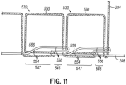
- a top of each chain stitch comprises a section of needle thread extending above the quilted panel.
- a bottom of each chain stitch comprises two different portions. One portion comprises two sections of needle thread and one section of looper thread. The other portion of the bottom of the chain stitch comprises three sections of looper thread.
- the side of each chain stitch comprises a section of needle thread.
- the sewing assembly further comprises a needle bar, needles secured to the needle bar, needle thread passing through each needle, a needle plate having holes through which the needles extend, loopers below the needle plate from which looper thread is provided to form chain stitches extending through the quilted panel without reducing the height of the quilted panel, a retainer bar below the needle plate movable from side-to-side and spreaders secured to the retainer bar.
- the feed assembly further comprises endless feed belts for moving the input web under the needles, the needle plate being inside the endless feed belts.
- the machine further comprises a controller programmed to operate the first and second servo motors at different or overlapping times.
- One rotation of the first drive pulley driven by the first servo motor completes one stroke of the needles and one cycle of the retainer bar and loopers.
- One rotation or portion thereof of the second drive pulley rotates the endless feed belts a programmed distance to move the input web a predetermined distance.
- the predetermined distance may be any distance but in most instances is from 0.25 to 4.0 inches, for example.
- Another aspect of the invention is a method of quilting an input web.
- the method includes providing a quilting machine including a sewing assembly powered by a first servo motor and a feed assembly powered by a second servo motor.
- the method further comprises moving the layered input web through the quilting machine using the feed assembly to form chain stitches in the input web without compressing the quilted panel using the sewing assembly.
- only one of the feed assembly and sewing assembly operates at a time.
- both the feed assembly and sewing assembly may operate at the same time for a pre-programmed amount of time.
- a computer program product for quilting webs that includes a non-transitory computer-readable storage medium.
- the storage medium includes program code that is configured, when executed by one or more processors, to cause the quilting machine to active the appropriate servo motor at the desired time to move the input web a desired distance and then complete a portion of a chain stitch.
- the program code further causes the quilting machine to move the pre-contact roller to the appropriate position via the third servo motor.
- Another aspect of the invention is a quilted panel comprising a first lofted layer having a first height, a second lofted layer having a second height and spaced stitch lines joining the layers and extending through the layers.
- Each of the stitch lines comprises multiple chain stitches.
- Each chain stitch comprises two sides, a top and a bottom. Each of the sides extends through the first and second lofted layers and comprises two sections of needle thread.
- the top of the chain stitch comprises one section of needle thread and the bottom of the chain stitch comprises two sections of needle thread and three sections of looper thread.
- the linear distance between the top and bottom of the stitch is the sum of the first and second heights.
- the quilted panel may comprise a top lofted layer, a bottom lofted layer and a middle layer between the top and bottom lofted layers.
- Spaced stitch lines extend through the layers.
- Each of the stitch lines comprises multiple chain stitches.
- Each of the chain stitches comprises two sides, a top and a bottom. Each of the sides extends through the layers and comprises one section of needle thread.
- the top of the chain stitch comprises one section of needle thread extending above the top lofted layer.
- a portion of the bottom of the chain stitch comprises two sections of needle thread and one section of looper thread below the bottom lofted layer. None of the layers is compressed.
- At least one of the lofted layers may be foam or may be made of pocketed springs or may be fiber or any combination thereof.
- the quilted panel may comprise a top layer, a bottom layer and a middle layer between the top and bottom layers.
- Spaced stitch lines extend through the layers.
- Each of the stitch lines comprises multiple chain stitches.
- Each of the chain stitches comprises two sides, a top and a bottom. Each of the sides extends through the layers and comprises one section of needle thread.
- the top of the chain stitch comprises one section of needle thread extending above the top layer.
- a portion of the bottom of the chain stitch comprises two sections of needle thread and one section of looper thread below the bottom layer. None of the layers is compressed.
- At least one of the layers may be made at least partially of foam or of fiber.
- At least one layer may be made of at least some pocketed springs.
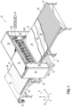
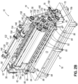
- FIGS. 1 , 2A and 2B provide perspective views of a multi-needle quilting machine 10 in accordance with an embodiment of the invention.
- the machine 10 may be used, for example, to quilt webs of multi-layered material without compressing the webs.
- the layers may include foam, fiber or pocketed spring blankets or any combination thereof used in the manufacture of mattresses.
- the machine 10 has an upstream or input end 14 and a downstream or output end 16.
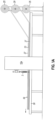
- the words "left” and "right” will refer to the machine as oriented as seen from the front, as shown in FIG. 2A .
- the machine 10 includes a base 12 and a frame 18 supported by the base 12.
- the base 12 has a generally planar top 13. Although one configuration of base 12 is shown, the base may be any other configuration. Although one configuration of frame 18 is shown, the frame may be any other configuration.
- the frame 18 comprises left and right vertically oriented frame legs 19a, 19b, respectively, a middle frame member 54, two diagonal frame members 56 and a top frame member 58.
- the middle frame member 54 comprises two hollow spanners 60 and two mounting plates 62, each mounting plate 62 being secured to one of the frame legs 19 and each of the hollow spanners 60 extending between mounting plates 62 of middle frame member 54.
- FIG. 1 shows a supply table 20 supporting an input web 22 comprising multiple pieces of lofted material (e.g., a facing piece 24, a middle piece 26, and a backing piece 28) enters the machine 10 at the input end 14 of the machine 10.
- the supply table 20 is illustrated being a non-motorized table comprising multiple rollers 21.
- the supply table may be motorized or any known table used in the industry.
- FIG. 1 also shows an output table 30 supporting a quilted panel 32 exiting the machine 10 at the output end 16.
- the output table 30 comprises a conveyor 31 powered by a servo-motor 33.
- the output table 30 is illustrated being a motorized table. However, the output table may be non-motorized or any known table used in the industry.
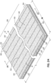
- the quilted panel 32 comprises the three pieces of lofted material 24, 26 and 28 sewn together with multiple parallel, spaced stitch lines 34 as shown in detail in FIGS. 24 and 25 .
- the input web 22 is shown made from three pieces of lofted material 24, 26 and 28, each being a separate layer in the quilted panel 32, any number of pieces of material pre-cut to size may be quilted together using the quilting machine 10 to form a quilted panel having any number of layers without compressing the layers.
- FIG. 1 also shows guard panels 36 used to protect an operator from injury during operation of the machine 10.
- FIG. 1A illustrates another embodiment of quilting machine 10a which is identical to quilting machine 10 but includes a cutter 2. Rather than individual pieces of lofted material pre-cut to size prior to entering the quilting machine 10a, FIG. 1A shows a roll 25 containing a web of first lofted material 27, a roll 29 containing a web of second lofted material 33 and a roll 35 containing a web of a third lofted material 37.
- any input web may be a pocketed spring web or non-lofted material.
- the input web 22 moves through the machine 12 in an incremental fashion, as opposed to a continuous fashion, via operation of a feed assembly 38.
- the feed assembly 38 comprises a feed servo-motor 40 supported by one of two frame legs 19a, 19b.
- the operation of the feed servo-motor 40 is controlled by the controller 50.
- the frame 18 further comprises left and right L-shaped braces 42a, 42b, respectively, one on each side of the machine 10.
- Each L-shaped brace 42a, 42b comprises a horizontal member 44a, 44b secured to one of the frame legs 19a, 19b, respectively, and a vertical member 46a, 46b secured to the generally planar top 13 of base 12.
- each of the left and right L-shaped braces 42a, 42b extends forwardly from the left and right frame legs 19a, 19b, respectively.
- operation of the feed servo-motor 40 rotates a drive pulley 48 located outside a mounting plate 52.
- the feed servo-motor 40 is located inside the mounting plate 52.
- the mounting plate 52 is secured to the left frame leg 19a.
- the feed assembly 38 further comprises a feed drive shaft 64 supported by four rear brackets 66, each rear bracket 66 being secured to one of the frame legs 19a, 19b. As best shown in FIG. 3 , a bearing assembly 68 is secured to each of the rear brackets 66 to facilitate rotation of the feed drive shaft 64. A feed pulley 70 is located outside the left most rear bracket 66 and is operatively coupled to the feed drive shaft 64 such that rotation of the feed pulley 70 rotates the feed drive shaft 64. As best shown in FIG. 4 , an endless drive belt 72 surrounds the drive pulley 48, the feed pulley 70 and an adjustable tensioner 74 for adjusting the tension of the endless drive belt 72. The controller 50 controls the operation of the feed servo-motor 40.
- the feed assembly 38 further comprises a front shaft 76 supported by four front brackets 78, each front bracket 78 being secured to one of the left and right L-shaped braces 42a, 42b, respectively.
- a bearing assembly 68 is secured to each of the front brackets 78 to facilitate rotation of the front shaft 76.
- a plurality of pulleys 77 are secured to the front shaft 76 in desired locations. See FIG. 3 .
- endless feed belts 80 surround the pulleys 77 secured to the front shaft 76 and pulleys 65 secured to the feed drive shaft 64.
- the endless feed belts 80 are rotated by rotation of the feed drive shaft 64 caused by rotation of the drive pulley 48 rotated by the feed servo-motor 40.
- the input web 22 exits the supply table 20 the input web 22 rests upon the endless feed belts 80 and is moved downstream in the machine 10 by the rotation of the endless feed belts 80.
- the feed assembly 38 further comprises two transition rollers 82 located at the rear of the machine 10 mounted to brackets 84 supported by transition posts 86.
- the transition posts 86 are bolted or otherwise secured to the top 13 of base 12.
- Each of the transition rollers 82 extends between the brackets 84 and is located behind the endless feed belts 80.
- the transition rollers 82 are not driven, but rather rotate as the quilted panel 32 passes over them from the machine 10 to the output table 30.
- the drawings show two transition rollers 82, any number of transition rollers may be used to provide a smooth path for the quilted panel 32 to move from the machine 10 onto the output table 30.
- the feed assembly 38 further comprises a pre-contact roller 98 located at the front of the machine 10.
- the height of the pre-contact roller 98 is controlled by linear actuators 100 powered by a platen servo-motor 102. When power is provided to the linear actuators 100, the linear actuators 100 lift the pre-contact roller 98 upwardly.
- a torque tube 104 extends between the linear actuators 100.
- each linear actuator 100 is bolted to a large lift plate 106 which is bolted to a small plate 108 of an L-shaped lifter 112 which is bolted to a platen 114.
- the platen 114 extends between the L-shaped lifters 112.
- An arm 116 extends forwardly from each of the L-shaped lifters 112.
- the pre-contact roller 98 extends between holes 118 at the front of each of the arms 116 (only one being shown in FIG. 12 ).
- the machine 10 further comprises a plurality of riser plates 88 secured to the top 13 of base 12.
- a needle plate 90 is welded or otherwise secured to the upper surfaces 92 at four locations 94 of each of the riser plates 88.
- the riser plates 88 are located between the endless feed belts 80 to not interfere with the movement of the endless feed belts 80.
- the needle plate 90 is located inside the endless feed belts 80.
- the needle plate 90 has a plurality of holes 96, one per needle 120 (nine shown).
- the transfer assembly 124 is located above the sewing servo-motor 130 and supported by the frame 12 and, more particularly, by the top frame member 58. As best shown in FIG. 6 , the transfer assembly 124 comprises inner and outer mounting brackets 134, 136 secured to the top frame member 58, respectively. Rear bearing assemblies 138 are attached to the inner and outer mounting brackets 134, 136, respectively. A rotatable transfer shaft 140 extends through the rear bearing assemblies 138 and rotates about an axis A, as shown in FIG. 7A . An outside transfer pulley 142 is secured to an outside end of the rotatable transfer shaft 140 and an inside transfer pulley 144 is secured to an inside end of the rotatable transfer shaft 140.
- the crank assembly 126 is in front of the transfer assembly 124 and in front of the top frame member 58. As best shown in FIGS. 5 and 6 , the crank assembly 126 comprises a first front bearing assembly 146 secured to the inner mounting bracket 134 and a second front bearing assembly 148 secured to a mounting bracket 150.
- the mounting bracket 150 is supported by the frame 12 and, more particularly, by the top frame member 58.
- a crank drive shaft 152 extends between the first and second front bearing assemblies 146, 148, respectively, and rotates about an axis AA, as shown in FIG. 7A .
- a crank pulley 154 is secured to one end of the crank drive shaft 152 and upon rotation functions to rotate the crank drive shaft 152.
- An endless transfer belt 164 surrounds the crank pulley 154 and the inside transfer pulley 144.
- a belt tensioner 145 connected to an L-shaped mounting bracket 147 is manually set to provide the proper tension to the endless transfer belt 164.
- the L-shaped mounting bracket 147 is secured to the top frame member 58.
- the crank assembly 126 further comprises two rotatable cranks 156, each crank 156 being secured to an end of the crank drive shaft 152.
- One rotation of the crank drive shaft 152 causes one rotation of the cranks 156.
- an upper end 180 of a drive rod 158 is secured to a narrow portion 178 of a crank 156 with a bolt 182 such that one rotation of the crank 156 equals one stroke of the drive rod 158.
- a bracket 159 is pivotally secured to the lower end 184 of each drive rod 158 with a bolt 186.
- the two brackets 159 (only one being shown in FIGS. 7A and 7B ) are secured to a needle bar 160 having a hollow interior 162.
- two spaced hollow members 172 are secured to the horizontally oriented spanners 60 of frame 12.
- a spacer 174 is secured to each of the hollow members 172 in front thereof and a rail 176 is secured to each of the spacers 174 in front thereof.
- a carriage 178 is secured to another spacer 177 which is secured to the needle bar 160.
- the machine has two carriages 178. Each carriage 178 is configured to engage one of the two rails 176 such that the needle bar 160 moves in a generally vertical direction and does not separate from the rails 176.
- the rails 176 are thereby configured to reciprocate the needle bar 160 in a generally linear path perpendicular to the quilting plane Q (see FIGS. 11A-11G ) in response to rotation of the crank pulley 154.
- each of the needles 120 is six inches in length. However, the needles may be any desired length.
- An endless drive belt 166 surrounds the drive pulley 132 rotated by the servo-motor 130, the outside transfer pulley 142, an indexer pulley 168 described below and a belt tensioner 170.
- the position of the belt tensioner 170 is changed manually.
- the operation of the sewing servo-motor 130 which rotates the drive pulley 132 is controlled by the controller 50.
- the indexer assembly 128 of the machine 10 is driven by rotation of the indexer pulley 168 rotated by the endless drive belt 166 and functions to oscillate a looper shaft 188 and move a retainer bar 190.
- the looper shaft 188 extends through openings 192 in the riser plates 88 and the retainer bar 190 extends through cutouts 194 in the riser plates 88 above looper shaft 188.
- a plurality of spreaders 191 are secured to the retainer bar 190.
- the indexer assembly 128 of the machine 10 comprises an indexer input shaft 196 connected to the indexer pulley 168 such that rotation of the indexer pulley 168 by the endless drive belt 166 rotates the indexer input shaft 196.
- the indexer input shaft 196 extends through an outer wall 198 of an indexer housing 200 and ends in an inner bearing assembly 199 having a bearing mount 201 attached to an inner wall 202 of the indexer housing 200.
- the indexer housing 200 also has an inner wall 202, a front wall 204, a rear wall 206, a top 208 and a bottom 210.
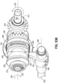
- the indexer input shaft 196 extends (from left to right as seen in FIG. 8B ) through an outer bearing assembly 212 having a bearing mount 214 secured to the outer wall 198 of the indexer housing 200, a drive bevel gear 216, a spacer 218 surrounding the indexer input shaft 196, a barrel cam 220 and inner bearing assembly 199 including a bearing mount 201 secured to the inner wall 202 of the indexer housing 200.
- the barrel cam 220 is attached to the indexer input shaft 196 such that upon rotation of the indexer input shaft 196, the barrel cam 220 rotates.
- the barrel cam 220 has a groove 222 machined therein to move a thruster 224 linearly in the direction of the y-axis 7.
- the thruster 224 has an extension 226 which rides inside groove 222 of the barrel cam 220 as the barrel cam 220 rotates to move the thruster 224 linearly in the direction of the y-axis 7.
- the machine 10 comprises a plurality of sewing stations 280 arranged in a row (e.g., nine shown) spaced laterally along the row.
- the lateral spacing in the row may be selected so that each sewing station 280 is offset from its neighboring sewing station along the y-axis 7 by a fixed distance d 1 (e.g., 12 inches) corresponding to the distance between needles 120 and corresponding stitch lines 34 produced by the machine 10.
- This spacing may enable the machine 10 to simultaneously produce stitch lines 34 having a desired spacing by synchronous operation of the sewing stations 280.
- FIGS. 11A-11G depict a portion of the looper assembly 270 including the looper 282, a looper holder 318, the retainer bar 190 and the spreader 191.
- the looper holder 318 couples the looper 282 to the looper shaft 188.
- the looper 282 further includes a hook 320 having a tip 322 at a forward end thereof, and a base 324 at a rearward end thereof from which the hook 320 extends.
- the hook 320 includes a longitudinal bore or channel that connects an opening 326 at the back or rearward side of the looper 282 with an opening or eye 328 ( FIG. 11D ) at the tip 322.
- Looper thread 288 from the looper thread spool 278 enters the opening 326 in the back of the looper 282 and emerges from the eye 328 of looper 282.
- the base 324 of looper 282 may be secured to the looper holder 318 by a set screw 330.
- a rearward end of spreader 191 may form a bracket that couples the spreader 191 to a retainer bar 190.
- FIGS. 15 and 16 depict a looper thread tensioner 293 similar to needle thread tensioner 292 of the corresponding needle assembly 268 and a thread tension monitor 294 identical to the thread tension monitor of the corresponding needle assembly 268.
- the looper thread tensioner 293 is identical to the one disclosed in U.S. Patent Application No. 15/662,750 .
- the looper thread 288 may be received from the looper thread spool 278 and directed to the thread tensioner 293 by a guide bracket 332 secured to base 12.
- the guide bracket 332 has a lower thread guide 334 and an upper thread guide 336. After leaving the upper thread guide 336 of the guide bracket 332, the looper thread 288 enters the thread tensioner 293. After exiting the thread tensioner 293, the looper thread 288 may pass through the thread tension monitor 294 before being provided to the respective looper 282.
- the position of the needle 120 may be described in terms of the angular position of the cranks 156.
- the positions of the cranks 156 are considered to be at a 0-degree position when the needle 120 is at its most retracted position above the quilting plane Q along its axis NA, or its Top Dead Center (TDC) position.
- TDC Top Dead Center
- BDC Bottom Dead Center
- the angular position of the cranks 156 also define the positions of these elements.
- the orientation of the needle 120, looper 282, and spreader 191, or the "stitch forming elements" 120, 282, 191 may be fully defined as a function of the angular position of the cranks 156, with each stitch cycle beginning at the 0-degree reference position and repeating for each 360 degrees of rotation.
- FIG. 11A provides a perspective view that illustrates the positions of the stitch forming elements 120, 282, 191 at a point in the stitch cycle associated with the 0-degree position of the cranks 156.
- the needle 120 is fully retracted in its TDC or home position
- the looper 282 is in its most forward or home position
- the spreader 191 is in its home position
- the needle thread 284 is wrapped around the hook 320 of looper 282 and around the looper thread 288.
- the feed assembly 38 indexes the input web 22 rearwardly or downstream as shown by the arrow 335 in a position direction along the x-axis 6 (to the left in FIG. 11B ).
- the needle thread 284 is drawn through an eye 312 of needle 120 downwardly until it contacts the top surface 23 of input web 22 (see arrow 285), across the top surface 23 of the input web 22 below the platen 114 (to the left in FIG.
- the looper thread 288 is pulled through the hook 320 of looper 282 (see arrow 289), passes through the loop 297 of needle thread 284 around the hook 320 of looper 282 and through another loop 299 of needle thread 284, moves upstream across the bottom surface 25 of the input web 22 and around the two sections of needle thread 284 which become the sides of the chain stitches, and back through the loop 299 of needle thread 284. This process repeats itself each time the input web is moved downstream.
- the cranks 156 rotating from their 0-degree positions, the needle 120 lowers from its TDC or home position and begins to move toward the input web 22.
- the spreader 191 begins to move from its home position shown in FIG. 11A towards an extended position direction along the y-axis 7 shown by arrow 195.
- the looper 282 remains stationary in its home position.
- the looper 282 begins to move rearwardly from its home position (to the left in FIG. 11C ) as shown by the arrow 197 in FIG. 11D .
- the needle 120 is illustrated passing through the input web 22.
- the spreader 191 is still moving towards its fully extended position furthest along the Y-axis from its home position.
- the looper thread 288 gets grabbed by a notch 337 in the spreader 191 during the movement of the spreader 191 to open a triangle 321 having sides defined by the needle thread 284, the hook 320 of looper 282, and the looper thread 288.
- the spreader 190 when the cranks 156 have rotated to the 122 degree point in the stitch cycle, the spreader 190 is in its fully extended position. As the cranks 156 move between 122 degrees and 142 degrees, the spreader 190 dwells or remains in its fully extended position. When the cranks 156 reach 142 degrees, the spreader 190 begins to move towards its home position. as shown by the arrow 193 in FIG. 11E . When the cranks 156 have rotated to the 212 degree point in the stitch cycle, the spreader 191 is finally back to its home position.
- FIG. 11E depicts stitch forming elements 120, 282, 191 at a point in the stitch cycle when the cranks 156 are approaching their 180-degree positions as illustrated in FIG. 7B .
- the needle 120 is illustrated having passed through the input web 22.
- the looper 282 is illustrated moving further downstream or in a positive direction in the x-axis 6 from its position shown in FIG. 11D .
- the needle 120 has begun passing through the triangle 321.
- the spreader 191 is moving towards its home position, as indicated by arrow 193 and the looper 282 is still moving away its home position, as indicated by arrow 197.
- FIG. 11F depicts stitch forming elements 120, 282, 191 at a point in the stitch cycle when the cranks 156 are in their 180-degree positions as illustrated in FIG. 7B .
- the needle 120 is in its BDC position fully extended through the platen hole 95 in platen 114, the input web 22 and needle hole 96 of needle plate 90.
- the looper 282 is stationary in its rearward position (i.e., its most extended position in the positive direction of the x-axis 6), and the spreader 191 is moving upstream towards its home position as shown by arrow 193.
- the needle thread 284 passes through an eye 312 of needle 120 proximate the tip thereof and extends from the opposite side of the needle 120 to the last formed stitch 338.
- the looper thread 288 extends from the tip 322 of hook 320 to the last formed stitch 338, which is now completely formed but may remain to be tightened.
- the needle 120 begins to move upwardly as the cranks 156 rotate past the 180-degree position in the stitch cycle.
- the looper 282 is moving upstream towards its home position (e.g., in a negative direction with respect to x-axis 6), and the spreader 191 is still moving towards its home position, as indicated by arrow 193.
- the feed servo-motor 40 is activated by the controller 50, causing rotation of the endless feed belts 80, thereby moving the input web 22 a pre-programmed distance in the downstream direction which is depicted as the positive direction along the x-axis 6.
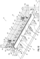
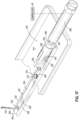
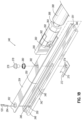
- FIGS. 17-19C a needle thread cutting assembly 340 whose operation is controlled by controller 50 is illustrated.
- the needle thread cutting assembly 340 extends across the machine generally in the direction of the y-axis 7 and functions to cut all the needle threads 284 simultaneously upon the completion of a job.
- FIG. 17 illustrates a portion of the needle thread cutting assembly 340 in an assembled condition.
- FIG. 18 shows the same portion of the needle thread cutting assembly 340 in a disassembled condition.
- the needle thread cutting assembly 340 comprises a rail 342 secured to the platen 114. As shown in FIG.
- the rail 342 has a bottom 344 having a plurality of keyhole slots 345 (only one being shown), sides 348 and lips 350 extending towards each other from sides 346 which define an inner groove 351 in rail 342 inside which moves a slider 354.
- each keyhole slot 345 has a circular end opening 346 which is aligned with an opening 352 (only one being shown) in the slider 354 when the needle thread cutting assembly 340 is at rest.
- a slider mounting block 356 is secured to the slider 354 and a clevis 358 is bolted to the slider mounting block 356 with bolt 360 and nut 362.
- a large nut 364 secures the clevis 358 to a moving rod 366 which is moved by a pneumatic cylinder 368 controlled by controller 50.
- the needle thread cutting assembly 340 further comprises a blade 370 having a cutting edge 372 and an opening 374.
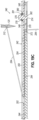
- a pin 376 has a removable snap ring 378 which fits inside a groove 381 ( FIGS. 19A-19C ) in the pin 376 such that to the snap ring 378 may be quickly and easily removed to remove the blade 370.
- the pin 376 fits inside the opening 374 of blade 370 and is welded to the blade 370.
- the pin 376 extends through an opening 382 in the slider 354 and moves inside the keyhole slot 345.
- the blade 370 moves along a slot (not shown) underneath the rail 342 as the pin 376 moves in the keyhole slot 345.
- a spring 380 is sandwiched between the removable snap ring 378 and the slider 354 to urge the pin 376 upwardly, thus keeping the blade 370 against the slider 354.
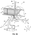
- FIG. 19B illustrates the needle thread cutting assembly 340 being activated by the controller 50, the pneumatic cylinder 368 extending the moving rod 366 to move the slider 354, blade 370 and pin 376 away from the pneumatic cylinder 368.
- the openings 352 of the movable slider 354 pull the needle threads 284 (only one being shown) through the openings 312 in needles 120 (only one being shown), the needle threads 284 still extending through the stationary circular end openings 346 of the keyhole slots 345 (only one being shown) of the rail 342.
- FIG. 19C illustrates the needle thread cutting assembly 340 being further activated by the controller 50, the pneumatic cylinder 368 further extending the moving rod 366 to move the slider 354, blade 370 and pin 376 further away from the pneumatic cylinder 368.
- the openings 352 (only one being shown) of the movable slider 354 continue to pull the needle threads 284 (only one being shown) through the openings 312 in needles 120 (only one being shown), the needle threads 284 still extending through the stationary circular end openings 346 of the keyhole slots 345 (only one being shown) of the rail 342 until the cutting edges 372 of blades 370 (only one being shown) cut the needle threads 284 (only one being shown).
- the moving rod 366 is pulled back inside the pneumatic cylinder 368 to the position shown in FIG. 19A .
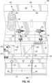
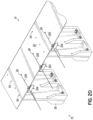
- FIGS. 20-21B three (of nine) looper thread cutting assemblies 384 are illustrated, each one of which is controlled by controller 50.
- each looper thread cutting assembly 384 is secured to the needle plate 90 with fasteners 386 and functions to cut one the looper threads 288 upon the completion of a job.
- FIG. 21A illustrates a portion of a looper thread cutting assembly 384 in a partially assembled condition before the looper thread 288 is cut.
- FIG. 21A illustrates a blade 390 in a home position and a cover 392 pulled away from the needle plate 90.
- FIG. 21B shows the same portion of the looper thread cutting assembly 340 in a partially assembled condition after the looper thread 288 is cut.
- FIG. 21B illustrates the blade 390 in a finished position.
Landscapes
- Engineering & Computer Science (AREA)
- Textile Engineering (AREA)
- Computer Hardware Design (AREA)
- Microelectronics & Electronic Packaging (AREA)
- Physics & Mathematics (AREA)
- Electromagnetism (AREA)
- Mechanical Engineering (AREA)
- Sewing Machines And Sewing (AREA)
- Treatment Of Fiber Materials (AREA)
Applications Claiming Priority (3)
| Application Number | Priority Date | Filing Date | Title |
|---|---|---|---|
| US16/205,886 US11015274B2 (en) | 2018-11-30 | 2018-11-30 | Quilting machine |
| EP19890949.1A EP3887586B1 (de) | 2018-11-30 | 2019-10-15 | Steppmaschine |
| PCT/US2019/056232 WO2020112264A1 (en) | 2018-11-30 | 2019-10-15 | Quilting machine |
Related Parent Applications (1)
| Application Number | Title | Priority Date | Filing Date |
|---|---|---|---|
| EP19890949.1A Division EP3887586B1 (de) | 2018-11-30 | 2019-10-15 | Steppmaschine |
Publications (3)
| Publication Number | Publication Date |
|---|---|
| EP4579020A2 true EP4579020A2 (de) | 2025-07-02 |
| EP4579020A3 EP4579020A3 (de) | 2025-07-09 |
| EP4579020B1 EP4579020B1 (de) | 2025-12-31 |
Family
ID=70848556
Family Applications (2)
| Application Number | Title | Priority Date | Filing Date |
|---|---|---|---|
| EP19890949.1A Active EP3887586B1 (de) | 2018-11-30 | 2019-10-15 | Steppmaschine |
| EP25176698.6A Active EP4579020B1 (de) | 2018-11-30 | 2019-10-15 | Steppmaschine |
Family Applications Before (1)
| Application Number | Title | Priority Date | Filing Date |
|---|---|---|---|
| EP19890949.1A Active EP3887586B1 (de) | 2018-11-30 | 2019-10-15 | Steppmaschine |
Country Status (3)
| Country | Link |
|---|---|
| US (1) | US11015274B2 (de) |
| EP (2) | EP3887586B1 (de) |
| WO (1) | WO2020112264A1 (de) |
Families Citing this family (5)
| Publication number | Priority date | Publication date | Assignee | Title |
|---|---|---|---|---|
| CN115125678A (zh) * | 2021-03-26 | 2022-09-30 | 本田技研工业株式会社 | 缝制装置、弯针的定位方法 |
| CN114164576B (zh) * | 2021-07-14 | 2022-11-22 | 河南印都数码科技有限公司 | 条幅缝合制筒装置 |
| JP2024021581A (ja) * | 2022-08-04 | 2024-02-16 | Juki株式会社 | 空縫い目カッター |
| CN115522322B (zh) * | 2022-11-28 | 2023-07-21 | 佛山市众联机械科技有限公司 | 一种床垫里料缝合设备及应用该设备的弹簧床垫加工工艺 |
| US12593929B2 (en) | 2023-11-03 | 2026-04-07 | L&P Property Management Company | Bedding or seating product and method of disassembling product |
Family Cites Families (35)
| Publication number | Priority date | Publication date | Assignee | Title |
|---|---|---|---|---|
| US29268A (en) | 1860-07-24 | Improvement in sewing-machines | ||
| US3406647A (en) | 1967-02-20 | 1968-10-22 | Elwood Realties Ltd | Single thread knotted lockstitch seam |
| US3903714A (en) | 1968-08-06 | 1975-09-09 | Statni Vyzkumny Ustav Textilni | Quilted fabric and method |
| US3635785A (en) | 1970-01-19 | 1972-01-18 | Beacon Mfg Co | Stitched nonwoven fabric utilizing a foam layer and a fibrous layer |
| US3960095A (en) * | 1975-03-14 | 1976-06-01 | Story Wayne G | Automatic quilting machine |
| US4408552A (en) * | 1978-03-15 | 1983-10-11 | Atsushige Kondo | Apparatus for automatically producing comforters |
| IT1110724B (it) * | 1979-02-09 | 1986-01-06 | Meca Snc | Dispositivo di comando del movimento trasversale di un carro portapezza in una macchina trapuntatrice |
| US4327653A (en) | 1980-01-21 | 1982-05-04 | Levi Strauss & Co. | Continuous sewer |
| JPS5888510U (ja) | 1981-12-10 | 1983-06-15 | シルバ−工業株式会社 | 燃焼器具用芯 |
| US4467737A (en) * | 1983-12-05 | 1984-08-28 | Breck Jr Louis W | Programmable sewing machine |
| CH667475A5 (de) * | 1985-05-03 | 1988-10-14 | Gegauf Fritz Ag | Stick- oder steppmaschine fuer grossflaechige stoffbahnen. |
| US5224856A (en) | 1990-01-31 | 1993-07-06 | Nippon Kokan Kabushiki Kaisha | Surface combustion burner |
| US5154130A (en) | 1991-09-30 | 1992-10-13 | Leggett & Platt, Incorporated | Multi-needle double lock chain stitch tack, jump and thread trimming quilting method and apparatus |
| DE19641638C2 (de) | 1995-10-09 | 2002-03-28 | Juki Kk | Verfahren zur Ausbildung eines Knotens beim Kettenstichnähen und Kettenstich-Nähmaschine zur Ausbildung eines solchen Knotens |
| US6187411B1 (en) | 1996-10-04 | 2001-02-13 | The Boeing Company | Stitch-reinforced sandwich panel and method of making same |
| US6178903B1 (en) * | 1997-04-01 | 2001-01-30 | L&P Property Management Company | Web-fed chain-stitch single-needle mattress cover quilter with needle deflection compensation |
| US7191718B1 (en) | 1997-04-01 | 2007-03-20 | L&P Property Management Company | Servo driven quilter |
| US6145456A (en) | 1999-05-07 | 2000-11-14 | L&P Property Management Company | Quilting machine with adjustable presser plate and method of operating the quilting machine |
| US6736078B2 (en) * | 2002-03-01 | 2004-05-18 | L&P Property Management Company | Soft goods slitter and feed system for quilting |
| US7789028B2 (en) | 2002-03-06 | 2010-09-07 | L&P Property Management Company | Chain-stitch quilting with separate needle and looper drive |
| US7143705B2 (en) * | 2002-03-06 | 2006-12-05 | L & P Property Management Company | Multiple horizontal needle quilting machine and method |
| US6889622B2 (en) | 2002-10-22 | 2005-05-10 | L&P Property Management Company | Programmable tucking attachment for a sewing machine and method |
| US6802271B2 (en) | 2003-01-08 | 2004-10-12 | Atlanta Attachment Company | Automatic border sewing system |
| KR20080082361A (ko) * | 2007-03-08 | 2008-09-11 | 썬스타 특수정밀 주식회사 | 자수 미싱 |
| DE102007060388B4 (de) | 2007-05-09 | 2015-10-08 | Nähmaschinenfabrik Emil Stutznäcker GmbH & Co. KG | Vielnadelnähmaschine sowie Verfahren zum Nähen von großflächigem Nähgut |
| US20110165397A1 (en) | 2010-01-06 | 2011-07-07 | Ray Roe | Stitch-Bonded Flame-Resistant Fabrics |
| EP3068937B1 (de) | 2013-11-14 | 2019-01-09 | Alberto Landoni | Mehrnadelsteppmaschine und entsprechendes steppverfahren |
| JP2015136827A (ja) | 2014-01-21 | 2015-07-30 | トヨタ自動車株式会社 | 内装部材とその製造方法 |
| GB2531808A (en) | 2014-11-03 | 2016-05-04 | Short Brothers Plc | Methods and precursors for manufacturing a perforated composite part |
| US9968202B2 (en) | 2015-02-13 | 2018-05-15 | L&P Property Management Company | Pocketed spring comfort layer and method of making same |
| US10060061B2 (en) | 2015-07-09 | 2018-08-28 | Bargain Basement Fitness, LLC | Bobbinless sewing machine and stitch |
| US10260184B2 (en) | 2017-05-11 | 2019-04-16 | L&P Property Management Company | Quilting machine |
| US10781544B2 (en) | 2017-05-11 | 2020-09-22 | L&P Property Management Company | Quilting machine |
| US20200385893A1 (en) | 2017-11-29 | 2020-12-10 | Roberto TROVI | Recyclable quilt |
| CN108374241B (zh) * | 2018-04-16 | 2023-07-25 | 安徽省萧县徽星机械制造有限公司 | 一种新型高效缝被机 |
-
2018
- 2018-11-30 US US16/205,886 patent/US11015274B2/en active Active
-
2019
- 2019-10-15 EP EP19890949.1A patent/EP3887586B1/de active Active
- 2019-10-15 WO PCT/US2019/056232 patent/WO2020112264A1/en not_active Ceased
- 2019-10-15 EP EP25176698.6A patent/EP4579020B1/de active Active
Also Published As
| Publication number | Publication date |
|---|---|
| EP3887586B1 (de) | 2025-05-21 |
| EP3887586A4 (de) | 2022-08-17 |
| EP4579020B1 (de) | 2025-12-31 |
| US20200173079A1 (en) | 2020-06-04 |
| WO2020112264A1 (en) | 2020-06-04 |
| US11015274B2 (en) | 2021-05-25 |
| EP3887586A1 (de) | 2021-10-06 |
| EP4579020A3 (de) | 2025-07-09 |
Similar Documents
| Publication | Publication Date | Title |
|---|---|---|
| EP3887586B1 (de) | Steppmaschine | |
| US11578441B2 (en) | Quilted panel | |
| US5154130A (en) | Multi-needle double lock chain stitch tack, jump and thread trimming quilting method and apparatus | |
| EP4585737B1 (de) | Verfahren zum steppen eines geschichteten eingabenetzes | |
| JP2646238B2 (ja) | 多層柔撓布地加工物を縫い合わせるための縫製機 | |
| US10781544B2 (en) | Quilting machine | |
| EP3622106B1 (de) | Steppmaschine | |
| JP2000107473A (ja) | パイピングを付けられたポケット開口の製作のための裁縫設備 | |
| US4649842A (en) | Method for the automatical sewing of quilting patterns in fabric webs, especially bed sackings or ticks of (wadded) bed quilts | |
| DE10125047A1 (de) | Strickereimaschine | |
| US3371630A (en) | Border panel manufacturing machine | |
| EP3068937B1 (de) | Mehrnadelsteppmaschine und entsprechendes steppverfahren | |
| DE3801820A1 (de) | Verfahren und einrichtung zum steppen und schneiden von polsterteilen und aehnlichen werkstuecken | |
| JP2000254370A (ja) | パイピングを付けられたポケット開口の製作のための縫製設備 | |
| US4256048A (en) | Knife mechanism for twin needle sewing apparatus | |
| KR100426449B1 (ko) | 패드 자동 생산기 | |
| KR200276410Y1 (ko) | 패드 자동 생산기 | |
| CN119083050A (zh) | 连续送料多机头绗缝设备及绗缝方法 | |
| WO2007080608A1 (en) | Device for applying ribbons or tapes, relative method of application and multi-needle sewing machine comprising said application device |
Legal Events
| Date | Code | Title | Description |
|---|---|---|---|
| PUAI | Public reference made under article 153(3) epc to a published international application that has entered the european phase |
Free format text: ORIGINAL CODE: 0009012 |
|
| STAA | Information on the status of an ep patent application or granted ep patent |
Free format text: STATUS: THE APPLICATION HAS BEEN PUBLISHED |
|
| REG | Reference to a national code |
Ref country code: DE Ref legal event code: R079 Free format text: PREVIOUS MAIN CLASS: D05B0069120000 Ipc: D05B0011000000 Ref country code: DE Ref legal event code: R079 Ref document number: 602019080044 Country of ref document: DE Free format text: PREVIOUS MAIN CLASS: D05B0069120000 Ipc: D05B0011000000 |
|
| PUAL | Search report despatched |
Free format text: ORIGINAL CODE: 0009013 |
|
| AC | Divisional application: reference to earlier application |
Ref document number: 3887586 Country of ref document: EP Kind code of ref document: P |
|
| AK | Designated contracting states |
Kind code of ref document: A2 Designated state(s): AL AT BE BG CH CY CZ DE DK EE ES FI FR GB GR HR HU IE IS IT LI LT LU LV MC MK MT NL NO PL PT RO RS SE SI SK SM TR |
|
| AK | Designated contracting states |
Kind code of ref document: A3 Designated state(s): AL AT BE BG CH CY CZ DE DK EE ES FI FR GB GR HR HU IE IS IT LI LT LU LV MC MK MT NL NO PL PT RO RS SE SI SK SM TR |
|
| RIC1 | Information provided on ipc code assigned before grant |
Ipc: D05B 69/12 20060101ALI20250604BHEP Ipc: D05B 63/00 20060101ALI20250604BHEP Ipc: D05B 35/00 20060101ALI20250604BHEP Ipc: D05B 33/00 20060101ALI20250604BHEP Ipc: D05B 27/12 20060101ALI20250604BHEP Ipc: D05B 19/12 20060101ALI20250604BHEP Ipc: D05B 11/00 20060101AFI20250604BHEP |
|
| STAA | Information on the status of an ep patent application or granted ep patent |
Free format text: STATUS: REQUEST FOR EXAMINATION WAS MADE |
|
| 17P | Request for examination filed |
Effective date: 20250807 |
|
| GRAP | Despatch of communication of intention to grant a patent |
Free format text: ORIGINAL CODE: EPIDOSNIGR1 |
|
| STAA | Information on the status of an ep patent application or granted ep patent |
Free format text: STATUS: GRANT OF PATENT IS INTENDED |
|
| RIC1 | Information provided on ipc code assigned before grant |
Ipc: D05B 11/00 20060101AFI20250811BHEP Ipc: D05B 19/12 20060101ALI20250811BHEP Ipc: D05B 27/12 20060101ALI20250811BHEP Ipc: D05B 33/00 20060101ALI20250811BHEP Ipc: D05B 35/00 20060101ALI20250811BHEP Ipc: D05B 63/00 20060101ALI20250811BHEP Ipc: D05B 69/12 20060101ALI20250811BHEP |
|
| INTG | Intention to grant announced |
Effective date: 20250916 |
|
| GRAS | Grant fee paid |
Free format text: ORIGINAL CODE: EPIDOSNIGR3 |
|
| GRAA | (expected) grant |
Free format text: ORIGINAL CODE: 0009210 |
|
| STAA | Information on the status of an ep patent application or granted ep patent |
Free format text: STATUS: THE PATENT HAS BEEN GRANTED |
|
| AC | Divisional application: reference to earlier application |
Ref document number: 3887586 Country of ref document: EP Kind code of ref document: P |
|
| AK | Designated contracting states |
Kind code of ref document: B1 Designated state(s): AL AT BE BG CH CY CZ DE DK EE ES FI FR GB GR HR HU IE IS IT LI LT LU LV MC MK MT NL NO PL PT RO RS SE SI SK SM TR |
|
| REG | Reference to a national code |
Ref country code: CH Ref legal event code: F10 Free format text: ST27 STATUS EVENT CODE: U-0-0-F10-F00 (AS PROVIDED BY THE NATIONAL OFFICE) Effective date: 20251231 Ref country code: GB Ref legal event code: FG4D |
|
| REG | Reference to a national code |
Ref country code: DE Ref legal event code: R096 Ref document number: 602019080044 Country of ref document: DE |
|
| REG | Reference to a national code |
Ref country code: IE Ref legal event code: FG4D |
|
| REG | Reference to a national code |
Ref country code: LT Ref legal event code: MG9D |
|
| PG25 | Lapsed in a contracting state [announced via postgrant information from national office to epo] |
Ref country code: NO Free format text: LAPSE BECAUSE OF FAILURE TO SUBMIT A TRANSLATION OF THE DESCRIPTION OR TO PAY THE FEE WITHIN THE PRESCRIBED TIME-LIMIT Effective date: 20260331 |
|
| PG25 | Lapsed in a contracting state [announced via postgrant information from national office to epo] |
Ref country code: FI Free format text: LAPSE BECAUSE OF FAILURE TO SUBMIT A TRANSLATION OF THE DESCRIPTION OR TO PAY THE FEE WITHIN THE PRESCRIBED TIME-LIMIT Effective date: 20251231 Ref country code: HR Free format text: LAPSE BECAUSE OF FAILURE TO SUBMIT A TRANSLATION OF THE DESCRIPTION OR TO PAY THE FEE WITHIN THE PRESCRIBED TIME-LIMIT Effective date: 20251231 |
|
| PG25 | Lapsed in a contracting state [announced via postgrant information from national office to epo] |
Ref country code: RS Free format text: LAPSE BECAUSE OF FAILURE TO SUBMIT A TRANSLATION OF THE DESCRIPTION OR TO PAY THE FEE WITHIN THE PRESCRIBED TIME-LIMIT Effective date: 20260331 |
|
| PG25 | Lapsed in a contracting state [announced via postgrant information from national office to epo] |
Ref country code: LV Free format text: LAPSE BECAUSE OF FAILURE TO SUBMIT A TRANSLATION OF THE DESCRIPTION OR TO PAY THE FEE WITHIN THE PRESCRIBED TIME-LIMIT Effective date: 20251231 |