EP4574403A1 - Stanzsystem zur formung einer verbundkomponente für eine struktur und verfahren zur stanzformung - Google Patents
Stanzsystem zur formung einer verbundkomponente für eine struktur und verfahren zur stanzformung Download PDFInfo
- Publication number
- EP4574403A1 EP4574403A1 EP24222205.7A EP24222205A EP4574403A1 EP 4574403 A1 EP4574403 A1 EP 4574403A1 EP 24222205 A EP24222205 A EP 24222205A EP 4574403 A1 EP4574403 A1 EP 4574403A1
- Authority
- EP
- European Patent Office
- Prior art keywords
- liner
- blank
- heated
- tooling
- press
- Prior art date
- Legal status (The legal status is an assumption and is not a legal conclusion. Google has not performed a legal analysis and makes no representation as to the accuracy of the status listed.)
- Pending
Links
Images


Classifications
-
- B—PERFORMING OPERATIONS; TRANSPORTING
- B29—WORKING OF PLASTICS; WORKING OF SUBSTANCES IN A PLASTIC STATE IN GENERAL
- B29C—SHAPING OR JOINING OF PLASTICS; SHAPING OF MATERIAL IN A PLASTIC STATE, NOT OTHERWISE PROVIDED FOR; AFTER-TREATMENT OF THE SHAPED PRODUCTS, e.g. REPAIRING
- B29C70/00—Shaping composites, i.e. plastics material comprising reinforcements, fillers or preformed parts, e.g. inserts
- B29C70/04—Shaping composites, i.e. plastics material comprising reinforcements, fillers or preformed parts, e.g. inserts comprising reinforcements only, e.g. self-reinforcing plastics
- B29C70/28—Shaping operations therefor
- B29C70/40—Shaping or impregnating by compression not applied
- B29C70/42—Shaping or impregnating by compression not applied for producing articles of definite length, i.e. discrete articles
- B29C70/46—Shaping or impregnating by compression not applied for producing articles of definite length, i.e. discrete articles using matched moulds, e.g. for deforming sheet moulding compounds [SMC] or prepregs
-
- B—PERFORMING OPERATIONS; TRANSPORTING
- B29—WORKING OF PLASTICS; WORKING OF SUBSTANCES IN A PLASTIC STATE IN GENERAL
- B29C—SHAPING OR JOINING OF PLASTICS; SHAPING OF MATERIAL IN A PLASTIC STATE, NOT OTHERWISE PROVIDED FOR; AFTER-TREATMENT OF THE SHAPED PRODUCTS, e.g. REPAIRING
- B29C51/00—Shaping by thermoforming, i.e. shaping sheets or sheet like preforms after heating, e.g. shaping sheets in matched moulds or by deep-drawing; Apparatus therefor
- B29C51/08—Deep drawing or matched-mould forming, i.e. using mechanical means only
-
- B—PERFORMING OPERATIONS; TRANSPORTING
- B29—WORKING OF PLASTICS; WORKING OF SUBSTANCES IN A PLASTIC STATE IN GENERAL
- B29C—SHAPING OR JOINING OF PLASTICS; SHAPING OF MATERIAL IN A PLASTIC STATE, NOT OTHERWISE PROVIDED FOR; AFTER-TREATMENT OF THE SHAPED PRODUCTS, e.g. REPAIRING
- B29C31/00—Handling, e.g. feeding of the material to be shaped, storage of plastics material before moulding; Automation, i.e. automated handling lines in plastics processing plants, e.g. using manipulators or robots
- B29C31/04—Feeding of the material to be moulded, e.g. into a mould cavity
- B29C31/08—Feeding of the material to be moulded, e.g. into a mould cavity of preforms to be moulded, e.g. tablets, fibre reinforced preforms, extruded ribbons, tubes or profiles; Manipulating means specially adapted for feeding preforms, e.g. supports conveyors
-
- B—PERFORMING OPERATIONS; TRANSPORTING
- B29—WORKING OF PLASTICS; WORKING OF SUBSTANCES IN A PLASTIC STATE IN GENERAL
- B29C—SHAPING OR JOINING OF PLASTICS; SHAPING OF MATERIAL IN A PLASTIC STATE, NOT OTHERWISE PROVIDED FOR; AFTER-TREATMENT OF THE SHAPED PRODUCTS, e.g. REPAIRING
- B29C35/00—Heating, cooling or curing, e.g. crosslinking or vulcanising; Apparatus therefor
- B29C35/02—Heating or curing, e.g. crosslinking or vulcanizing during moulding, e.g. in a mould
- B29C35/0288—Controlling heating or curing of polymers during moulding, e.g. by measuring temperatures or properties of the polymer and regulating the process
-
- B—PERFORMING OPERATIONS; TRANSPORTING
- B29—WORKING OF PLASTICS; WORKING OF SUBSTANCES IN A PLASTIC STATE IN GENERAL
- B29C—SHAPING OR JOINING OF PLASTICS; SHAPING OF MATERIAL IN A PLASTIC STATE, NOT OTHERWISE PROVIDED FOR; AFTER-TREATMENT OF THE SHAPED PRODUCTS, e.g. REPAIRING
- B29C51/00—Shaping by thermoforming, i.e. shaping sheets or sheet like preforms after heating, e.g. shaping sheets in matched moulds or by deep-drawing; Apparatus therefor
- B29C51/18—Thermoforming apparatus
-
- B—PERFORMING OPERATIONS; TRANSPORTING
- B29—WORKING OF PLASTICS; WORKING OF SUBSTANCES IN A PLASTIC STATE IN GENERAL
- B29C—SHAPING OR JOINING OF PLASTICS; SHAPING OF MATERIAL IN A PLASTIC STATE, NOT OTHERWISE PROVIDED FOR; AFTER-TREATMENT OF THE SHAPED PRODUCTS, e.g. REPAIRING
- B29C51/00—Shaping by thermoforming, i.e. shaping sheets or sheet like preforms after heating, e.g. shaping sheets in matched moulds or by deep-drawing; Apparatus therefor
- B29C51/26—Component parts, details or accessories; Auxiliary operations
- B29C51/261—Handling means, e.g. transfer means, feeding means
-
- B—PERFORMING OPERATIONS; TRANSPORTING
- B29—WORKING OF PLASTICS; WORKING OF SUBSTANCES IN A PLASTIC STATE IN GENERAL
- B29C—SHAPING OR JOINING OF PLASTICS; SHAPING OF MATERIAL IN A PLASTIC STATE, NOT OTHERWISE PROVIDED FOR; AFTER-TREATMENT OF THE SHAPED PRODUCTS, e.g. REPAIRING
- B29C51/00—Shaping by thermoforming, i.e. shaping sheets or sheet like preforms after heating, e.g. shaping sheets in matched moulds or by deep-drawing; Apparatus therefor
- B29C51/26—Component parts, details or accessories; Auxiliary operations
- B29C51/42—Heating or cooling
- B29C51/421—Heating or cooling of preforms, specially adapted for thermoforming
-
- B—PERFORMING OPERATIONS; TRANSPORTING
- B29—WORKING OF PLASTICS; WORKING OF SUBSTANCES IN A PLASTIC STATE IN GENERAL
- B29C—SHAPING OR JOINING OF PLASTICS; SHAPING OF MATERIAL IN A PLASTIC STATE, NOT OTHERWISE PROVIDED FOR; AFTER-TREATMENT OF THE SHAPED PRODUCTS, e.g. REPAIRING
- B29C70/00—Shaping composites, i.e. plastics material comprising reinforcements, fillers or preformed parts, e.g. inserts
- B29C70/04—Shaping composites, i.e. plastics material comprising reinforcements, fillers or preformed parts, e.g. inserts comprising reinforcements only, e.g. self-reinforcing plastics
- B29C70/28—Shaping operations therefor
- B29C70/54—Component parts, details or accessories; Auxiliary operations, e.g. feeding or storage of prepregs or SMC after impregnation or during ageing
- B29C70/542—Placing or positioning the reinforcement in a covering or packaging element before or during moulding, e.g. drawing in a sleeve
-
- B—PERFORMING OPERATIONS; TRANSPORTING
- B29—WORKING OF PLASTICS; WORKING OF SUBSTANCES IN A PLASTIC STATE IN GENERAL
- B29L—INDEXING SCHEME ASSOCIATED WITH SUBCLASS B29C, RELATING TO PARTICULAR ARTICLES
- B29L2031/00—Other particular articles
- B29L2031/30—Vehicles, e.g. ships or aircraft, or body parts thereof
- B29L2031/3005—Body finishings
-
- B—PERFORMING OPERATIONS; TRANSPORTING
- B29—WORKING OF PLASTICS; WORKING OF SUBSTANCES IN A PLASTIC STATE IN GENERAL
- B29L—INDEXING SCHEME ASSOCIATED WITH SUBCLASS B29C, RELATING TO PARTICULAR ARTICLES
- B29L2031/00—Other particular articles
- B29L2031/30—Vehicles, e.g. ships or aircraft, or body parts thereof
- B29L2031/3076—Aircrafts
Definitions
- stamp forming One such process to form the composite material into the desired shape is stamp forming.
- Conventional stamping processes use a heater to heat a thermoplastic composite blank to a predetermined temperature, that is above a crystallization temperature. Then, the thermoplastic composite blank is introduced to a tool where pressure is applied to form the thermoplastic composite blank into the desired shape.
- the thermoplastic composite blank begins to cool as soon as the thermoplastic composite blank leaves the heater and rapidly cools when the thermoplastic composite blank contacts the tool.
- the tool To achieve the desired shape during the conventional stamping process, the tool must shape the thermoplastic composite blank before a temperature below the crystallization temperature occurs.
- the present disclosure provides a stamping system for forming a composite component for a structure.
- the stamping system includes a blank formed of a composite material.
- the composite material has a crystallization temperature.
- the stamping system also includes a blank heater configured to heat the blank to a melt temperature to define a heated blank.
- the melt temperature is above the crystallization temperature of the composite material.
- the stamping system includes a press movable to an open position to present an opening to receive the heated blank and movable to a closed position to stamp the heated blank.
- the press includes tooling having a predetermined configuration configured to change the heated blank to the predetermined configuration of the tooling when the press is in the closed position to stamp the heated blank.
- the stamping system also includes a heat transfer component cooperating with the heated blank and the tooling to delay onset of the crystallization temperature of the heated blank when the heated blank is disposed in the opening of the press.
- the structure 10 may be any suitable configuration, and non-limiting examples may include movable platforms which may include vehicles, trains, watercraft, flight vehicles, equipment, farm equipment, robotics, etc.; non-movable platforms which may include buildings, equipment, farm equipment, robotics, etc.; or any other suitable structures. Therefore, the composite component 14 may be formed in the desired configuration to accommodate the desired structure 10, including but not limited to the movable platforms and the non-movable platforms discussed above. As suggested above, the composite component 14 may be part of the flight vehicle, and non-limiting examples of the flight vehicle may include an aircraft, a helicopter, a jet, a vertical take-off and landing (VTOL) aircraft, a space shuttle, a drone, a payload, or any other suitable flight vehicle.
- VTOL vertical take-off and landing
- the stamping system 12 described herein a larger variety of the types of blanks 16 may be used to form different composite components 14, such as, for example, the blank 16 may be a thin-walled structure, a structure having one or more ply ramps, a structure having complex surface features, or any other blank that may be formed using the stamping system 12 described herein.
- the stamping system 12 also includes a heat transfer component 32 cooperating with the heated blank 16 and the tooling 29 to delay onset of the crystallization temperature of the heated blank 16 when the heated blank 16 is disposed in the opening 27 of the press 26. That is, the heat transfer component 32 decelerates heat transfer between the heated blank 16 and the tooling 29 when the press 26 is closed to delay the onset of the crystallization temperature of the heated blank 16. As such, the heat transfer component 32 decelerates heat transfer from the heated blank 16 when the press 26 is closed to delay the onset of the crystallization temperature of the heated blank 16.
- the cooling rate of the heated blank 16 is reduced, and thus, additional time is obtained to reach and maintain the full lamination pressure during the forming process. Therefore, by slowing down the cooling rate, a larger variety of the types of blanks 16 may be used to form different composite components 14. Furthermore, by slowing down the cooling rate, visco-elastic behavior of the heated blank 16 is controllable.
- the stamping system 12 may use various different features or ways to obtain the desired heating to delay the onset of the crystallization temperature, and some of these configurations are discussed below.
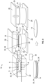
- the heat transfer component 32 may include a first liner 34 and a second liner 36.
- the first liner 34 and the second liner 36 may be in different locations depending on the configuration of FIGS. 2-4 .
- each of the first liner 34 and the second liner 36 creates a barrier configured to delay the onset of the crystallization temperature of the heated blank 16.
- the heat transfer component 32 may act as a barrier, buffer, insulator, or similarly, to slow down the cooling rate of the heated blank 16. Therefore, generally, the first liner 34 and the second liner 36 reduce the heat-transfer rate between the blank 16 and the tooling 29.
- the first liner 34 and the second liner 36 may be any suitable materials to delay the onset of the crystallization temperature, and non-limiting examples of the materials may include metallic material(s), polymer material(s), or any other suitable materials to delay the onset of the crystallization temperature. More specifically, examples of the materials of the first liner 34 and the second liner 36 may include steel, polyimide, Kapton, etc. Generally, the first liner 34 and the second liner 36 may be formed as a film, a layer, a foil, etc. Therefore, if using Kapton as the liners 34, 36, the liners 34, 36 are generally referred to as Kapton foil. Furthermore, if using steel as the liners 34, 36, the liners 34, 36 are generally referred to as steel foil. Generally, if using steel, the steel, the steel foil is a low-thermally-conductive type of steel material.
- the heat transfer component 32 is attached or affixed to the tooling 29. More specifically, the first liner 34 and the second liner 36 are attached to the tooling 29. That is, the first liner 34 covers the first face 28 of the tooling 29 and the second liner 36 covers the second face 30 of the tooling 29. Generally, when the press 26 is closed, the heated blank 16 is sandwiched between the first face 28 and the second face 30, to apply pressure to the heated blank 16.
- the first liner 34 abuts the first side 18 of the heated blank 16 and the second liner 36 abuts the second side 20 of the heated blank 16 when pressure is applied to the heated blank 16 via the tooling 29 through the press 26 which decelerates heat transfer from the heated blank 16 to delay the onset of the crystallization temperature of the heated blank 16.
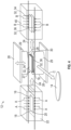
- the heat transfer component 32 is temporarily attached to the blank 16. More specifically, the first liner 34 and the second liner 36 are removably attached to the blank 16. That is, the first liner 34 covers the first side 18 of the blank 16 and the second liner 36 covers the second side 20 of the blank 16 during the forming process. Generally, when the press 26 is closed, the heated blank 16 is sandwiched between the first face 28 of the tooling 29 and the second face 30 of the tooling 29, to apply pressure to the heated blank 16.
- the first liner 34 abuts the first face 28 of the tooling 29 and the second liner 36 abuts the second face 30 of the tooling 29 when pressure is applied to the heated blank 16 via the tooling 29 through the press 26 which decelerates heat transfer from the heated blank 16 to delay the onset of the crystallization temperature of the heated blank 16. That is, the heat transfer component 32 decelerates heat transfer from the heated blank 16 when the press 26 is closed to delay the onset of the crystallization temperature of the heated blank 16.
- the stamping system 12 may include an end effector 38 configured to remove the first liner 34 and the second liner 36 from the composite component 14 when the press 26 is re-opened after forming the composite component 14. That is, once the composite component 14 is formed in the tooling 29, the press 26 is reopened, and the composite component 14 is movable out of the press 26 by a movable platform 24, such as a track, a robot, a shuttle, etc. Then, the end effector 38 may grab, engage, etc., the first liner 34 to de-attach or remove the first liner 34 from the first side 18 of the composite component 14.
- the end effector 38 may grab, engage, etc., the second liner 36 to de-attach or remove the second liner 36 from the second side 20 of the composite component 14.
- the end effector 38 may be attached to a movable arm and/or a robot. It is to be appreciated that the end effector 38 may first remove the first liner 34 from the first side 18 and then remove the second liner 36 from the second side 20, or, the end effector 38 may first remove the second liner 36 from the second side 20 and then remove the first liner 34 from the first side 18. Alternatively, the end effector 38 may remove the first liner 34 and the second liner 36 at the same time or simultaneously.
- the heat transfer component 32 is separate from the blank 16 and the press 26/the tooling 29. That is, the heat transfer component 32 is not attached nor affixed to the blank 16, and similarly, not attached nor affixed to the tooling 29.
- two heaters 22, 40 are used, one for the press 26/the tooling 29 and one for the blank 16.
- the blank heater 22 is used to heat the blank 16 to the melt temperature.
- the stamping system 12 may include a liner heater 40 configured to heat the first liner 34 and the second liner 36 to a predetermined temperature to define a heated first liner 34 and a heated second liner 36.
- the liner heater 40 may be any suitable configuration to heat the first liner 34 and the second liner 36 to the melt temperature, and non-limiting examples may include an oven, such as but not limited to conductive heating or inductive heating, or any other suitable heater. Also, in the example of FIG. 4 , the first liner 34 and the second liner 36 may be formed of the foil, such as but not limited to, steel foil.
- the heated first liner 34 and the heated second liner 36 are movable into the press 26 to heat the first face 28 of the tooling 29 and the second face 30 of the tooling 29. Additionally, when the blank 16 is heated to the melt temperature, the heated blank 16 is then movable into the press 26. Therefore, the heated blank 16, the heated first liner 34, and the heated second liner 36 are disposed in the opening 27 of the press 26 such that the heated first liner 34 is disposed between the first side 18 of the heated blank 16 and the tooling 29 and the heated second liner 36 is disposed between the second side 20 of the heated blank 16 and the tooling 29.
- the heated first liner 34 is disposed between the first side 18 of the heated blank 16 and the first face 28 of the tooling 29, and the heated second liner 36 is disposed between the second side 20 of the heated blank 16 and the second face 30 of the tooling 29.
- the press 26 is closed, the heated blank 16 is sandwiched between the heated first liner 34, the heated second liner 36, the first face 28 of the tooling 29, and the second face 30 of the tooling 29.
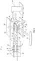
- the heat transfer component 32 may include a tool heater 42 configured to heat the first face 28 of the tooling 29 and the second face 30 of the tooling 29 inside of the opening 27 of the press 26.
- the tool heater 42 may include a movable platform 24 configured to move the tool heater 42 into the opening 27 of the press 26 in an initial heating state to heat the first face 28 (of the tooling 29) and the second face 30 (of the tooling 29) to a predetermined temperature.
- the movable platform 24 may also move out of the opening 27 of the press 26 in a final heated state when the predetermined temperature is reached.
- the movable platform 24 may be any suitable configuration, and non-limiting examples may include a track as shown in FIG. 5 , shuttling rail, a robot and/or robotic arm as shown in FIG. 6 , or any other suitable movable platform to move the tool heater 42 into and out of the press 26.
- the tool heater 42 may be any suitable configuration, and non-limiting examples may include an infrared heater, an inductive heater, a conductive heater, or any other suitable tool heater to heat the first face 28 and the second face 30 of the tooling 29.
- the tool heater 42 may include a first susceptor 44 attached to, or embedded in, the first face 28 of the tooling 29, and a second susceptor 46 attached to, or embedded in, the second face 30 of the tooling 29.
- the first susceptor 44 and the second susceptor 46 cooperates with the inductive heater to inductively heat the first face 28 and the second face 30 of the tooling 29.
- the first susceptor 44 and the second susceptor 46 are illustrated as dash-dot-dot-dashed lines in FIGS. 5 and 6 , to indicate the optional feature of using the susceptors 44, 46 if the tool heater 42 is the inductive heater.
- the present disclosure also provides a method of stamp forming the composite component 14 for the structure 10.
- stamping system 12 and the method thin-walled structures, small-scale structures, and/or complex structures may be stamp formed on a large scale, and equipment requirements may be reduced.
- high-rate fabrication of the composite components 14 may be obtained using this stamping system 12 and the method herein.
- the method may have different steps or processes depending on the type of the heat transfer component 32 being used, and each of which are discussed below.
- the blank 16 is heated to the melt temperature via the blank heater 22 to define the heated blank 16.
- the melt temperature is above the crystallization temperature of the composite material.
- the plurality of arrows A in FIGS. 2-6 are representative of heating of the blank 16 in the blank heater 22.
- the blank 16 is formed of the composite material.
- the press 26 is closed on the heated blank 16. That is, once the heated blank 16 is disposed in the opening 27 of the press 26, the press 26 moves to the closed position. Then, pressure is applied to the heated blank 16 while the press 26 is closed to stamp the heated blank 16.
- the tooling 29 of the press 26 has the predetermined configuration configured to change the heated blank 16 to the predetermined configuration of the tooling 29 when the press 26 applies the pressure to the heated blank 16. More specifically, once the press 26 is in the closed position, the press 26 may apply pressure to the heated blank 16, through the tooling 29, to stamp or form the heated blank 16 into the desired form. The pressure applied to the heated blank 16, via the tooling 29 through the press 26, continues until the full lamination pressure is reached, and optionally, maintained for a predetermined amount of time, which completes the process of forming/stamping the composite component 14.
- the heated blank 16 begins to cool. Also, once engagement or contact occurs between the heated blank 16 and the tooling 29, heat transfer occurs. Furthermore, as the pressure is applied to the heated blank 16 via the tooling 29, heat transfer occurs. Therefore, it is desirable to slow down this heat transfer.
- the heat transfer component 32 described herein controls heat transfer to delay onset of the crystallization temperature of the heated blank 16.
- the method also includes controlling, via the heat transfer component 32, heat transfer between the heated blank 16 and the tooling 29 to delay onset of the crystallization temperature of the heated blank 16. By controlling heat transfer, the pressing time may be increased, which ensures that the time to reach full lamination pressure is achieved. In other words, by controlling heat transfer as described herein, the heated blank 16 may be pressed for a longer period of time if desired.
- the press 26 opens and the stamp formed composite component 14 is removed from the press 26.
- the composite component 14 is removed from the press 26 after forming the composite component 14. Therefore, to remove the completed composite component 14, the press 26 moves back to the open position to remove the composite component 14 therefrom. Now, the stamping process of the composite component 14 is complete, and the composite component 14 may move to a finishing process or assembly process as desired.
- the heat transfer component 32 includes the first liner 34 and the second liner 36. As discussed above, each of the first liner 34 and the second liner 36 creates the barrier to delay the onset of the crystallization temperature. Controlling, via the heat transfer component 32, heat transfer between the heated blank 16 and the tooling 29 further includes controlling, via the first liner 34 and the second liner 36, heat transfer between the heated blank 16 and the tooling 29 to delay onset of the crystallization temperature of the heated blank 16.
- the first liner 34 covers the first face 28 of the tooling 29 and the second liner 36 covers the second face 30 of the tooling 29.
- the first liner 34 and the second liner 36 are affixed to the first face 28 and the second face 30, respectively, of the tooling 29. Therefore, the first liner 34 and the second liner 36 remain attached to the tooling 29 during the process of forming the composite component 14. For example, when the press 26 moves to the open position and the closed position, the first liner 34 and the second liner 36 correspondingly move.
- controlling, via the first liner 34 and the second liner 36, heat transfer between the heated blank 16 and the tooling 29 further includes abutting the first liner 34 to the first side 18 of the heated blank 16 and abutting the second liner 36 to the second side 20 of the heated blank 16 when applying pressure to the heated blank 16 via the press 26.
- the heated blank 16 is sandwiched between the first face 28 of the tooling 29 and the first liner 34 relative to the first side 18 of the heated blank 16, and sandwiched between the second face 30 of the tooling 29 and the second liner 36 relative to the second side 20 of the heated blank 16.
- the first liner 34 and the second liner 36 create the barrier between the heated blank 16 and the first face 28 and the second face 30 to delay the onset of the crystallization temperature during stamping in the press 26.
- the press 26 opens to move back to the open position and the composite component 14 is removed from the press 26. Since the first liner 34 and the second liner 36 are attached to the tooling 29, these liners 34, 36 may be reused to repeat the forming process for a new blank.
- the first liner 34 covers the first side 18 of the blank 16 and the second liner 36 covers the second side 20 of the blank 16. That is, the first liner 34 and the second liner 36 are attached to the blank 16. However, the liners 34, 36 attached to the blank 16 are temporary until after the composite component 14 is stamped or formed, which is discussed further below.
- controlling, via the first liner 34 and the second liner 36, heat transfer between the heated blank 16 and the tooling 29 further includes abutting the first face 28 of the tooling 29 to the first liner 34 and abutting the second face 30 of the tooling 29 to the second liner 36 when applying pressure to the heated blank 16 via the press 26.
- the heated blank 16 is sandwiched between the first face 28 and the first liner 34 relative to the first side 18 of the heated blank 16, and sandwiched between the second face 30 and the second liner 36 relative to the second side 20 of the heated blank 16.
- the first liner 34 and the second liner 36 create the barrier between the heated blank 16 and the first face 28 and the second face 30 to delay the onset of the crystallization temperature during stamping in the press 26.
- the press 26 moves back to the open position and the composite component 14 is removed from the press 26.
- the first liner 34 is removed from the first side 18 of the composite component 14 after removing the composite component 14 from the tooling 29, and additionally, the second liner 36 is removed from the second side 20 of the composite component 14 after removing the composite component 14 from the tooling 29.
- the first liner 34 and the second liner 36 may be removed by the end effector 38 or any other suitable mechanism to grab/remove the liners 34, 36.
- any order of removing the liners 34, 36 from the composite component 14 is suitable for this process; that is, the first liner 34 may be removed first, the second liner 34, 36 may be removed first, or both of the liners 34, 36 may be removed at the same time.
- the composite component 14 may move to the finishing process or the assembly process as desired. When this process is repeated for a new blank, a new first liner and a new second liner is attached to the new blank.
- the first liner 34 and the second liner 36 are not attached to the press 26/the tooling 29 nor attached to the heated blank 16. Instead, the first liner 34 and the second liner 36 are movable independently of the heated blank 16 into the press 26, and the first liner 34 and the second liner 36 are heated separately from the blank 16. Therefore, in this configuration, the first liner 34 and the second liner 36 are heated via the liner heater 40 to define the heated first liner 34 and the heated second liner 36. Arrows B in FIG. 4 are representative of heating of the first liner 34 and the second liner 36 in the liner heater 40.
- heating the blank 16 via the blank heater 22 and heating the first liner 34 and the second liner 36 via the liner heater 40 occurs before inserting the blank 16 into the opening 27 of the press 26.
- heating the blank 16 via the blank heater 22 and heating the first liner 34 and the second liner 36 via the liner heater 40 occurs at the same time.
- the heated blank 16 moves into the press 26, and once the first liner 34 and the second liner 36 reach the predetermined temperature, the first liner 34 and the second liner 36 move into the press 26. More specifically, the first liner 34 and the second liner 36 enter the press 26 from the liner heater 40 while the heated blank 16 enters the press 26 from the blank heater 22.
- inserting the heated blank 16 into the opening 27 of the press 26 further includes inserting the heated first liner 34, the heated second liner 36, and the heated blank 16 into the opening 27 of the press 26 such that the heated first liner 34 is disposed between the first side 18 of the heated blank 16 and the tooling 29, and the heated second liner 36 is disposed between the second side 20 of the heated blank 16 and the tooling 29.
- the heated blank 16 is sandwiched between the first face 28 and the first liner 34 relative to the first side 18 of the heated blank 16, and sandwiched between the second face 30 and the second liner 36 relative to the second side 20 of the heated blank 16.
- the first liner 34 and the second liner 36 create the barrier between the heated blank 16 and the first face 28 and the second face 30 to delay the onset of the crystallization temperature during stamping in the tooling 29.
- the press 26 moves back to the open position and the composite component 14 is removed from the press 26 (arrow C in FIG. 4 is pointing at the composite component 14 after removal from the press 26), and the first liner 34 and the second liner 36 return to the liner heater 40 where the first liner 34 and the second liner 36 may be reheated to repeat the stamping/forming process for another blank.
- the heat transfer component 32 includes the tool heater 42.
- the first face 28 of the tooling 29 is heated via the tool heater 42 and the second face 30 of the tooling 29 is heated via the tool heater 42 before inserting the heated blank 16 into the opening 27 of the press 26.
- the tool heater 42 enters the press 26 to heat the first face 28 and the second face 30 of the tooling 29 while the blank 16 is heated in the blank heater 22 at a separate location.
- FIG. 5 and 6 are representative of heating of the first face 28 and the second face 30 of the tooling 29 via the tool heater 42.
- the movable platform 24 controls movement of the tool heater 42, and for illustrative purposes, FIG. 5 illustrates the movable platform 24 as the track, and FIG. 6 illustrates the movable platform 24 as the robot. Regardless of the configuration of the movable platform 24, the movable platform 24 controls movement of the tool heater 42 relative to the tooling 29 and the tool heater 42.
- the tool heater 42 is inserted into the opening 27 of the press 26 to heat the first face 28 and the second face 30, and once the first face 28 and the second face 30 reach the predetermined temperature, the tool heater 42 is removed from the opening 27 of the press 26, and then, the heated blank 16 may be inserted into the opening 27 of the press 26. That is, removing the tool heater 42 occurs before inserting the heated blank 16 into the opening 27 of the press 26.
- Arrow E in FIG. 5 is illustrative of moving to the next stage of this process after the tooling 29 has been heated and the blank 16 has been heated.
- the heated blank 16 is sandwiched between the first face 28 and the second face 30 of the tooling 29.
- the first face 28 and the second face 30 create the barrier between the heated blank 16 and the first face 28 and the second face 30 to delay the onset of the crystallization temperature during stamping in the press 26.
- the press 26 opens, and thus, moves back to the open position and the composite component 14 is removed from the tooling 29 (arrow C in FIGS. 5 and 6 is pointing at the composite component 14 after removal from the press 26). Then, the composite component 14 may move to the finishing process or the assembly process as desired.
- a controller may control the stamp forming process described herein.
- the controller may be in communication with the heaters 22, 40, 42, the press 26, any sensors, the movable platform 24, etc.
- the controller may determine/monitor temperatures of the heaters 22, 40, 42, the blank 16, the liners 34, 36, etc., and use this information to determine when to move the heated blank 16, open/close the press 26, when and how long to apply pressure to the heated blank 16, move the liners 34, 36, etc.
- the controller may include a processor and a memory, configured to execute instructions from the memory, via the processor to control the stamping system 12 and associated method. It should be realized that such block components may be comprised of any number of hardware, software, and/or firmware components configured to perform the specified functions.
- a stamping system for forming a composite component for a structure comprising: a blank formed of a composite material, wherein the composite material has a crystallization temperature; a blank heater configured to heat the blank to a melt temperature to define a heated blank, wherein the melt temperature is above the crystallization temperature of the composite material; a press movable to an open position to present an opening to receive the heated blank and movable to a closed position to stamp the heated blank, wherein the press includes tooling having a predetermined configuration configured to change the heated blank to the predetermined configuration of the tooling when the press is in the closed position to stamp the heated blank; and a heat transfer component cooperating with the heated blank and the tooling to delay onset of the crystallization temperature of the heated blank when the heated blank is disposed in the opening of the press.
- Clause 2 The stamping system as set forth in clause 1 wherein the heat transfer component includes a first liner and a second liner, wherein each of the first liner and the second liner creates a barrier configured to delay the onset of the crystallization temperature of the heated blank.
- Clause 3 The stamping system as set forth in clauses 1 or 2 wherein: the tooling includes a first face and a second face facing each other; the opening is disposed between the first face and the second face when the press is in the open position; the first liner covers the first face of the tooling and the second liner covers the second face of the tooling; and the first liner abuts a first side of the heated blank and the second liner abuts a second side of the heated blank when pressure is applied to the heated blank via the tooling through the press which decelerates heat transfer from the heated blank to delay the onset of the crystallization temperature of the heated blank.
- Clause 4 The stamping system as set forth in clauses 1 or 2 wherein: the tooling includes a first face and a second face facing each other; the opening is disposed between the first face and the second face when the press is in the open position; the blank includes a first side having the first liner covering the first side and a second side having the second liner covering the second side; and the first liner abuts the first face of the tooling and the second liner abuts the second face of the tooling when pressure is applied to the heated blank via the tooling through the press which decelerates heat transfer from the heated blank to delay the onset of the crystallization temperature of the heated blank.
- Clause 5 The stamping system as set forth in any one of clauses 1, 2, or 4 wherein the press is movable to the closed position to apply the pressure to the heated blank through the tooling to form the composite component, wherein the heat transfer component decelerates heat transfer from the heated blank when the press is closed to delay the onset of the crystallization temperature of the heated blank.
- Clause 6 The stamping system as set forth in any one of clauses 1, 2, 4, or 5 further including an end effector configured to remove the first liner and the second liner from the composite component when the press is re-opened after forming the composite component.
- Clause 7 The stamping system as set forth in clauses 1 or 2: further including a liner heater configured to heat the first liner and the second liner to a predetermined temperature to define a heated first liner and a heated second liner; and wherein the heated blank, the heated first liner, and the heated second liner are disposed in the opening of the press such that the heated first liner is disposed between a first side of the heated blank and the tooling and the heated second liner is disposed between a second side of the heated blank and the tooling.
- a liner heater configured to heat the first liner and the second liner to a predetermined temperature to define a heated first liner and a heated second liner
- the heated blank, the heated first liner, and the heated second liner are disposed in the opening of the press such that the heated first liner is disposed between a first side of the heated blank and the tooling and the heated second liner is disposed between a second side of the heated blank and the tooling.
- Clause 8 The stamping system as set forth in clause 1 wherein the heat transfer component includes a tool heater configured to heat a first face of the tooling and a second face of the tooling inside of the opening of the press.
- the heat transfer component includes a tool heater configured to heat a first face of the tooling and a second face of the tooling inside of the opening of the press.
- Clause 9 The stamping system as set forth in clauses 1 or 8 wherein the tool heater includes a movable platform configured to move the tool heater into the opening of the press in an initial heating state to heat the first face and the second face to a predetermined temperature, and move out of the opening of the press in a final heated state when the predetermined temperature is reached.
- Clause 10 The stamping system as set forth in any one of the preceding clauses wherein the press is movable to the closed position to apply a pressure to the heated blank through the tooling to form the composite component, wherein the heat transfer component decelerates heat transfer from the heated blank when the press is closed to delay the onset of the crystallization temperature of the heated blank.
- a method of stamp forming a composite component for a structure comprising: heating a blank, formed of a composite material, to a melt temperature via a blank heater to define a heated blank, wherein the melt temperature is above a crystallization temperature of a composite material; inserting the heated blank into an opening of a press; closing the press on the heated blank; applying a pressure to the heated blank while the press is closed to stamp the heated blank, wherein the press includes tooling having a predetermined configuration configured to change the heated blank to the predetermined configuration of the tooling when the press applies the pressure to the heated blank; and controlling, via a heat transfer component, heat transfer between the heated blank and the tooling to delay onset of the crystallization temperature of the heated blank.
- Clause 12 The method as set forth in clause 11 wherein: the heat transfer component includes a first liner and a second liner, each of the first liner and the second liner creates a barrier to delay the onset of the crystallization temperature; and controlling, via the heat transfer component, heat transfer between the heated blank and the tooling further comprises controlling, via the first liner and the second liner, heat transfer between the heated blank and the tooling to delay onset of the crystallization temperature of the heated blank.
- Clause 13 The method as set forth in clauses 11 or 12 wherein: the tooling includes a first face and a second face facing each other; the opening is disposed between the first face and the second face when the press is in an open position; the first liner covers the first face of the tooling and the second liner covers the second face of the tooling; and controlling, via the first liner and the second liner, heat transfer between the heated blank and the tooling further comprises abutting the first liner to a first side of the heated blank and abutting the second liner to a second side of the heated blank when applying pressure to the heated blank via the press.
- Clause 15 The method as set forth in any one of clauses 11, 12, or 14 further comprising: forming the composite component from pressing the heated blank in the press; removing the composite component from the press after forming the composite component; removing the first liner from the first side of the composite component after removing the composite component from the tooling; and removing the second liner from the second side of the composite component after removing the composite component from the tooling.
- Clause 16 The method as set forth in clauses 11 or 12: further comprising heating the first liner and the second liner via a liner heater to define a heated first liner and a heated second liner; and wherein inserting the heated blank into the opening of the press further comprises inserting the heated first liner, the heated second liner, and the heated blank into the opening of the press such that the heated first liner is disposed between a first side of the heated blank and the tooling, and the heated second liner is disposed between a second side of the heated blank and the tooling.
- Clause 17 The method as set forth in any one of clauses 11, 12, or 16 wherein heating the blank via the blank heater and heating the first liner and the second liner via the liner heater occurs before inserting the blank into the opening of the press.
- Clause 18 The method as set forth in any one of clauses 11, 12, 16, or 17 wherein heating the blank via the blank heater and heating the first liner and the second liner via the liner heater occurs at the same time.
Landscapes
- Engineering & Computer Science (AREA)
- Mechanical Engineering (AREA)
- Chemical & Material Sciences (AREA)
- Composite Materials (AREA)
- Physics & Mathematics (AREA)
- Health & Medical Sciences (AREA)
- Oral & Maxillofacial Surgery (AREA)
- Thermal Sciences (AREA)
- Robotics (AREA)
- Shaping Metal By Deep-Drawing, Or The Like (AREA)
- Casting Or Compression Moulding Of Plastics Or The Like (AREA)
- Moulding By Coating Moulds (AREA)
Applications Claiming Priority (1)
| Application Number | Priority Date | Filing Date | Title |
|---|---|---|---|
| US18/395,340 US20250205978A1 (en) | 2023-12-22 | 2023-12-22 | Stamping system for forming a composite component for a structure and a method of stamp forming |
Publications (1)
| Publication Number | Publication Date |
|---|---|
| EP4574403A1 true EP4574403A1 (de) | 2025-06-25 |
Family
ID=93925638
Family Applications (1)
| Application Number | Title | Priority Date | Filing Date |
|---|---|---|---|
| EP24222205.7A Pending EP4574403A1 (de) | 2023-12-22 | 2024-12-20 | Stanzsystem zur formung einer verbundkomponente für eine struktur und verfahren zur stanzformung |
Country Status (4)
| Country | Link |
|---|---|
| US (1) | US20250205978A1 (de) |
| EP (1) | EP4574403A1 (de) |
| JP (1) | JP2025111384A (de) |
| CN (1) | CN120191006A (de) |
Citations (2)
| Publication number | Priority date | Publication date | Assignee | Title |
|---|---|---|---|---|
| EP2656994A2 (de) * | 2012-04-25 | 2013-10-30 | Airbus Operations Limited | Mikrowellenhärtung von Verbundstoffmaterialien |
| WO2020234313A1 (fr) * | 2019-05-23 | 2020-11-26 | Institut De Recherche Technologique Jules Verne | Dispositif et procédé de fabrication d'une pièce en matériau composite |
Family Cites Families (6)
| Publication number | Priority date | Publication date | Assignee | Title |
|---|---|---|---|---|
| DE1812839A1 (de) * | 1968-12-05 | 1970-11-05 | Kannegiesser Maschinen | Verfahren und Vorrichtung zum zweiseitigen Bedrucken ein- oder mehrlagiger Textilstuecke |
| US4044188A (en) * | 1972-10-02 | 1977-08-23 | Allied Chemical Corporation | Stampable thermoplastic sheet reinforced with multilength fiber |
| US4943222A (en) * | 1989-04-17 | 1990-07-24 | Shell Oil Company | Apparatus for forming preformed material |
| DE102009019496A1 (de) * | 2009-05-04 | 2010-11-18 | Braun, Elisabeth | Vorrichtung und Verfahren zur Erwärmung warm umzuformender Werkstücke |
| TWI421161B (zh) * | 2011-07-13 | 2014-01-01 | Quanta Comp Inc | 高週波電磁感應加熱裝置及使用其加熱模具表面的方法 |
| GB201805320D0 (en) * | 2018-03-29 | 2018-05-16 | Mclaren Automotive Ltd | Diaphragm forming |
-
2023
- 2023-12-22 US US18/395,340 patent/US20250205978A1/en active Pending
-
2024
- 2024-12-18 JP JP2024221249A patent/JP2025111384A/ja active Pending
- 2024-12-20 CN CN202411894061.7A patent/CN120191006A/zh active Pending
- 2024-12-20 EP EP24222205.7A patent/EP4574403A1/de active Pending
Patent Citations (2)
| Publication number | Priority date | Publication date | Assignee | Title |
|---|---|---|---|---|
| EP2656994A2 (de) * | 2012-04-25 | 2013-10-30 | Airbus Operations Limited | Mikrowellenhärtung von Verbundstoffmaterialien |
| WO2020234313A1 (fr) * | 2019-05-23 | 2020-11-26 | Institut De Recherche Technologique Jules Verne | Dispositif et procédé de fabrication d'une pièce en matériau composite |
Also Published As
| Publication number | Publication date |
|---|---|
| US20250205978A1 (en) | 2025-06-26 |
| CN120191006A (zh) | 2025-06-24 |
| JP2025111384A (ja) | 2025-07-30 |
Similar Documents
| Publication | Publication Date | Title |
|---|---|---|
| EP3785881B1 (de) | Wechsel von blasformen bei blasformmaschinen | |
| US11167472B2 (en) | Method and apparatus for the additive manufacturing of a three-dimensional workpiece | |
| US10954577B2 (en) | Hot-forming line for manufacturing hot-formed and press-hardened steel-sheet products, and method for operating said hot-forming line | |
| US10876179B2 (en) | Method for producing hot-formed components | |
| EP3196006A1 (de) | Vorrichtung und verfahren zur herstellung einer verbundstruktur | |
| EP4574403A1 (de) | Stanzsystem zur formung einer verbundkomponente für eine struktur und verfahren zur stanzformung | |
| EP0621244A1 (de) | Verfahren und Vorrichtung zum Biegen und Härten einer Glasscheibe getragen auf einer Ringform | |
| WO2016005322A1 (de) | Applikationswerkzeug und applikationsverfahren | |
| US8365381B2 (en) | Vehicle closure member mounting | |
| DE69608772T2 (de) | Elektrisch angetriebene, flexibele Biegeform | |
| EP3291987B1 (de) | Produktionsanlage und verfahren zur herstellung von kfz-kennzeichenrohlingen | |
| US20200298456A1 (en) | Device and method for machining a plate-shaped workpiece for a motor vehicle | |
| DE102014114186A1 (de) | Verfahren und Vorrichtung zum Laminieren eines profilierten Faserformteils | |
| EP2219844A1 (de) | Giessmachinensystem und verfahren zur herstellung von metall/kunststoff-hybridbauteilen | |
| US11618544B2 (en) | Method for producing a structural section of a vehicle | |
| WO2014183934A1 (de) | Umformeinrichtung, bearbeitungsmaschine und verfahren zum thermoformen eines thermoplastisch verformbaren werkstückes | |
| JP7469049B2 (ja) | マグネシウムブラダーを用いて複合材構造体を製造するための方法とシステム | |
| US11203165B2 (en) | Methods and apparatus for embedding a wire intermittently | |
| DE102004019293A1 (de) | Verfahren zur Formung von Kunstoffplatten | |
| CA2926973C (en) | Aluminum warm forming multi-opening oven and production line | |
| DE102018213252B4 (de) | Verfahren zur Herstellung eines Kunststoffbauteils und Anlage zur Herstellung eines Kunststoffbauteils | |
| JP7015252B2 (ja) | 大量の物品を製造するための製造プラント並びに製造プラントを制御し且つ/又はモニタするための方法 | |
| CN119427779A (zh) | 冲压成型纤维增强热塑性复合组件的方法及相关系统 | |
| EP3793955A1 (de) | Verfahren zur herstellung von glasscheiben | |
| KR101452717B1 (ko) | 웨더스트립 제조 방법 |
Legal Events
| Date | Code | Title | Description |
|---|---|---|---|
| PUAI | Public reference made under article 153(3) epc to a published international application that has entered the european phase |
Free format text: ORIGINAL CODE: 0009012 |
|
| STAA | Information on the status of an ep patent application or granted ep patent |
Free format text: STATUS: THE APPLICATION HAS BEEN PUBLISHED |
|
| AK | Designated contracting states |
Kind code of ref document: A1 Designated state(s): AL AT BE BG CH CY CZ DE DK EE ES FI FR GB GR HR HU IE IS IT LI LT LU LV MC ME MK MT NL NO PL PT RO RS SE SI SK SM TR |
|
| STAA | Information on the status of an ep patent application or granted ep patent |
Free format text: STATUS: REQUEST FOR EXAMINATION WAS MADE |
|
| 17P | Request for examination filed |
Effective date: 20251217 |