EP4572094A1 - Permanentmagnetrotor und elektrische permanentmagnetdrehmaschine - Google Patents
Permanentmagnetrotor und elektrische permanentmagnetdrehmaschine Download PDFInfo
- Publication number
- EP4572094A1 EP4572094A1 EP22930138.7A EP22930138A EP4572094A1 EP 4572094 A1 EP4572094 A1 EP 4572094A1 EP 22930138 A EP22930138 A EP 22930138A EP 4572094 A1 EP4572094 A1 EP 4572094A1
- Authority
- EP
- European Patent Office
- Prior art keywords
- hole
- permanent magnet
- rotor
- radially
- magnet
- Prior art date
- Legal status (The legal status is an assumption and is not a legal conclusion. Google has not performed a legal analysis and makes no representation as to the accuracy of the status listed.)
- Withdrawn
Links
Images


Classifications
-
- H—ELECTRICITY
- H02—GENERATION; CONVERSION OR DISTRIBUTION OF ELECTRIC POWER
- H02K—DYNAMO-ELECTRIC MACHINES
- H02K1/00—Details of the magnetic circuit
- H02K1/06—Details of the magnetic circuit characterised by the shape, form or construction
- H02K1/22—Rotating parts of the magnetic circuit
- H02K1/27—Rotor cores with permanent magnets
- H02K1/2706—Inner rotors
- H02K1/272—Inner rotors the magnetisation axis of the magnets being perpendicular to the rotor axis
- H02K1/274—Inner rotors the magnetisation axis of the magnets being perpendicular to the rotor axis the rotor consisting of two or more circumferentially positioned magnets
- H02K1/2753—Inner rotors the magnetisation axis of the magnets being perpendicular to the rotor axis the rotor consisting of two or more circumferentially positioned magnets the rotor consisting of magnets or groups of magnets arranged with alternating polarity
- H02K1/276—Magnets embedded in the magnetic core, e.g. interior permanent magnets [IPM]
- H02K1/2766—Magnets embedded in the magnetic core, e.g. interior permanent magnets [IPM] having a flux concentration effect
-
- H—ELECTRICITY
- H02—GENERATION; CONVERSION OR DISTRIBUTION OF ELECTRIC POWER
- H02K—DYNAMO-ELECTRIC MACHINES
- H02K1/00—Details of the magnetic circuit
- H02K1/06—Details of the magnetic circuit characterised by the shape, form or construction
- H02K1/22—Rotating parts of the magnetic circuit
- H02K1/27—Rotor cores with permanent magnets
- H02K1/2706—Inner rotors
- H02K1/272—Inner rotors the magnetisation axis of the magnets being perpendicular to the rotor axis
- H02K1/274—Inner rotors the magnetisation axis of the magnets being perpendicular to the rotor axis the rotor consisting of two or more circumferentially positioned magnets
- H02K1/2753—Inner rotors the magnetisation axis of the magnets being perpendicular to the rotor axis the rotor consisting of two or more circumferentially positioned magnets the rotor consisting of magnets or groups of magnets arranged with alternating polarity
- H02K1/276—Magnets embedded in the magnetic core, e.g. interior permanent magnets [IPM]
-
- H—ELECTRICITY
- H02—GENERATION; CONVERSION OR DISTRIBUTION OF ELECTRIC POWER
- H02K—DYNAMO-ELECTRIC MACHINES
- H02K2213/00—Specific aspects, not otherwise provided for and not covered by codes H02K2201/00 - H02K2211/00
- H02K2213/03—Machines characterised by numerical values, ranges, mathematical expressions or similar information
Definitions
- Embodiments of the present invention relate to a permanent magnet rotor and a permanent magnet rotary electric machine using the same.
- HEV hybrid electric vehicles
- EV electric vehicles
- bridges are provided to mechanically support centrifugal force acting on a core on the radially outer side of flux barriers and on permanent magnets.
- a thick bridge is capable of alleviating stress caused by the centrifugal force.
- a leakage magnetic flux increases to lower performance such as torque.
- a first example describes a bridge width for achieving both a reduction in a leakage magnetic flux and mechanical strength of bridges, in a configuration in which flux barriers each have a top bridge and have, on a radially inner side, two center bridges.
- a second example describes that, in a configuration in which all the flux barriers have top bridges, and circumferentially inner flux barriers have two center bridges, by arranging the bridges of the flux barriers such that they are not aligned on a straight line, it is possible to reduce a leakage magnetic flux while maintaining mechanical strength.
- the core between the layers has a cantilever structure with the center bridges being a fixed end because the radially outer sides of the core portion sandwiched by the magnets are not restricted. Therefore, it is necessary to reduce bending stress acting on the roots of the bridges without lowing torque performance.
- An object of the present invention is to provide a permanent magnet rotor that achieves a reduction in bending stress acting on roots of bridges without lowing torque performance.
- a permanent magnet rotor includes: a rotor shaft extending in a rotation axis direction; a rotor core attached to the rotor shaft, and having, in each magnetic pole, a first outer through hole and a second outer through hole that are formed on a radially outer side to make a pair and a first inner through hole and a second inner through hole that are formed on a more radially inner side than the first outer through hole and the second outer through hole to make a pair; a first outer magnet and a second outer magnet housed in the first outer through hole and the second outer through hole respectively; and a first inner magnet and a second inner magnet housed in the first inner through hole and the second inner through hole respectively, wherein an outer opening angle between radially outward extension directions of a radially outer wall of the first outer through hole and a radially outer wall of the second outer through hole is larger than an inner opening angle between radially outward extension directions of a radially outer wall
- a permanent magnet rotor and a permanent magnet rotary electric machine according to an embodiment of the present invention will be hereinafter described with reference to the drawings.
- parts that are identical or similar to each other are denoted by common reference signs and a redundant description thereof will be omitted.
- FIG. 1 is a sectional longitudinal view illustrating a configuration example of the permanent magnet rotary electric machine 1 having the permanent magnet rotor 100 according to the embodiment.
- the permanent magnet rotary electric machine 1 has the permanent magnet rotor 100, a stator 10, two bearings 20, two bearing brackets 30, and a frame 40.
- the permanent magnet rotor 100 has a rotor shaft 110 extending in a direction of a rotation axis CL, a rotor core 120 attached to a radially outer side of the rotor shaft 110, and permanent magnets 130 embedded in the rotor core 120.
- a first outer magnet 131 and a first inner magnet 133 out of the permanent magnets 130 are illustrated, but details will be described later with reference to FIG. 2 .
- the stator 10 has a cylindrical stator core 11 arranged on the outer side of the outer peripheral surface of the rotor core 120 to surround the rotor core 120 and a stator winding 12 wound around the stator core 11.
- the two bearings 20 rotatably support the rotor shaft.
- Each of the two bearing brackets 30 statically support each of the two bearings 20.
- the frame 40 has a cylindrical shape, houses the stator 10, and has ends connected to the two bearing brackets 30 respectively to support these.
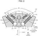
- FIG. 2 is a partial transverse sectional view illustrating the permanent magnets 130 and the rotor core 120 therearound in one magnetic pole of the permanent magnet rotor 100 according to the embodiment.
- the permanent magnet rotor 100 has an even number of magnetic poles 139, and the magnetic poles whose polarities are opposite, that is, the magnetic poles 139 whose magnetic lines of force are in opposite directions are alternately arranged to be adjacent to each other in the circumferential direction.
- FIG. 2 illustrates one of the magnetic poles 139.
- a direction parallel to the extension direction of the axis of the rotor shaft 110, that is, a direction (front-rear direction) perpendicular to FIG. 2 is defined as an axial direction.
- a direction extending away from the rotation axis CL ( FIG. 1 ) of the rotor shaft 110 is defined as a radial direction.
- a direction in which the permanent magnet rotor 100 rotates is defined as a circumferential direction.
- the permanent magnet rotor 100 has, in each of the magnetic poles, the first outer magnet 131, a second outer magnet 132, the first inner magnet 133, and a second inner magnet 134.
- the first outer magnet 131 and the second outer magnet 132 are arranged on the radially outer side of the first inner magnet 133 and the second inner magnet 134.
- the first outer magnet 131 and the second outer magnet 132 are formed to make a pair. Specifically, the first outer magnet 131 and the second outer magnet 132 line up in the circumferential direction, and are arranged such that a gap between the first outer magnet 131 and the second outer magnet 132, that is, their circumferential distance, becomes larger as they go toward the radially outer side.
- FIG. 2 illustrates, as an example, the case where the first outer magnet 131 and the second outer magnet 132 are symmetrical and the first inner magnet 133 and the second inner magnet 134 are symmetrical with respect to the center axis (d-axis) of the magnetic pole 139 in a cross section perpendicular to the axial direction, that is, the case of what is called a V-arrangement, but this is not restrictive, that is, the first outer magnet 131 and the second outer magnet 132 may be different in size, or their directions may be asymmetrical. Similarly, the first inner magnet 133 and the second inner magnet 134 may be different in size, or their directions may be asymmetrical.
- a first outer through hole 121, a second outer through hole 122, a first inner through hole 124, and a second inner through hole 125 for housing the first outer magnet 131, the second outer magnet 132, the first inner magnet 133, and the second inner magnet 134 respectively are formed.
- the first outer through hole 121, the second outer through hole 122, the first inner through hole 124, and the second inner through hole 125 are regions high in magnetic reluctance and each function as a flux barrier.
- the radially inner sides of the first outer through hole 121 and the second outer through hole 122 forming an outer layer are adjacent to each other across two inner center bridges 123 therebetween. Further, the radially outer portions of the first outer through hole 121 and the second outer through hole 122 communicate with a radially outer side of the rotor core 120. That is, there are no top bridges thereof.
- the radially inner sides of the first inner through hole 124 and the second inner through hole 125 forming an inner layer are adjacent to each other across two inner center bridges 126 therebetween. Further, the radially outer portions of the first inner through hole 124 and the second inner through hole 125 communicate with the radially outer side of the rotor core 120. That is, there are no top bridges thereof.
- an angle made by a radially outer wall 121a of the first outer through hole 121 and a radially outer wall 122a of the second outer through hole 122, that is, an opening angle between their radially outward extension directions will be called an outer opening angle ⁇ a.
- an angle made by a radially outer wall 124a of the first inner through hole 124 and a radially outer wall 125a of the second inner through hole 125, that is, an angle between their radially outward extension directions will be called an inner opening angle ⁇ b.
- the outer opening angle ⁇ a is larger than the inner opening angle ⁇ b. That is, the following formula (1) holds. 0 ⁇ ⁇ b ⁇ ⁇ a ⁇ 180 °
- the distance between the first outer through hole 121 and the second outer through hole 122 specifically, the distance between a circumferentially inner wall 121b of the first outer through hole 121 and a circumferentially inner wall 122b of the second outer through hole 122 will be called an inter-outer through hole length xa.
- the distance between the first inner through hole 124 and the second inner through hole 125 specifically, the distance between a circumferentially inner wall 124b of the first inner through hole 124 and a circumferentially inner wall 125b of the second inner through hole 125 will be called an inter-inner through hole length xb.
- FIG. 2 illustrates, as an example, the case where the inter-inner through hole length xb is larger than the inter-outer through hole length xa, that is, the following formula (2) holds. xa ⁇ xb
- the permanent magnet rotor 100 only needs to satisfy the condition that the outer opening angle ⁇ a is larger than the inner opening angle ⁇ b as represented by the above formula (1). That is, the condition that the inter-inner through hole length xb is larger than the inter-outer through hole length xa as represented by the formula (2) is not an essential condition though further improving the effect of this embodiment.
- FIG. 3 is a partial transverse sectional view illustrating the conventional example of the rotor core 120 around the permanent magnets 130 in the single magnetic pole 139 of the permanent magnet rotor according to the embodiment.
- an inner opening angle ⁇ b0 is equal to the outer opening angle ⁇ a.
- an inter-inner through hole length xb0 is equal to the inter-outer through hole length xa.
- This conventional example illustrated in FIG. 3 will be called a base shape.
- FIG. 4 is a partial transverse sectional view illustrating a first example of the rotor core 120 around the permanent magnets 130 in the single magnetic pole 139 of the permanent magnet rotor 100 according to the embodiment.
- the broken line represents the base-shaped one.
- the inner opening angle ⁇ b is smaller than the inner opening angle ⁇ b0 in the conventional example.
- point P1 at which the radially outer wall 124a of the first inner through hole 124 intersects with an opening and point P2 at which the radially outer wall 125a of the second inner through hole 125 intersects with an opening remain at their positions in the conventional example.
- first inner through hole 124 and the second inner through hole 125 have such a shape that the circumferential positions of the circumferentially inner wall 124b of the first inner through hole 124 and the circumferentially inner wall 125b of the second inner through hole 125 are maintained so that the inter-inner through hole length is left equal to the inter-inner through hole length xb0 in the conventional example. Accordingly, their radially inner ends move radially inward according to the change in their inclination.
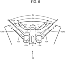
- FIG. 5 is a partial transverse sectional view illustrating a second example of the rotor core 120 around the permanent magnets 130 in the single magnetic pole 139 of the permanent magnet rotor 100 according to the embodiment.
- the contents of the second example are the same as the contents illustrated in FIG. 2 .
- the broken line represents the base-shaped one.
- the inner opening angle ⁇ b is smaller than the inner opening angle ⁇ b0 in the conventional example.
- the second example is the same as the first example in that point P1 at which the radially outer wall 124a of the first inner through hole 124 intersects with the opening and point P2 at which the radially outer wall 125a of the second inner through hole 125 intersects with the opening remain at the positions in the conventional example.
- the first inner through hole 124 and the second inner through hole 125 have such a shape that the inter-inner through hole length xb has a larger value than that of the inter-inner through hole length xb0 in the conventional example.
- FIG. 6 is a graph illustrating the effect of the first and second examples of the rotor core 120 around the permanent magnets 130 in the single magnetic pole 139 of the permanent magnet rotor 100 according to the embodiment.
- the horizontal axis represents cases, and three indexes regarding each case are shown. From the left, the first one is torque.
- the second one is stress A, which is the maximum stress in the outer center bridges 123, and the third one is stress B, which is the maximum stress in the inner center bridges 126.
- the first axis represents torque [P.U.] and the second axis represents stress [P.U.].
- case 1 to case 3 correspond to the permanent magnet rotor 100 according to this embodiment.
- the shape of the conventional example is set as a reference shape (base shape), and values on the vertical axis are based on those in the base shape. Therefore, the values of torque [P.U.] and stresses [P.U.] in the case of the base shape on the horizontal axis are 1.00.
- Case 2 where ⁇ a > ⁇ b and xa ⁇ xb, is a case corresponding to the permanent magnet rotor 100 according to this embodiment.
- case 3 ⁇ a > ⁇ b and xa ⁇ xb as in case 2, but the inclination is made such that the radially outer side fans out more, and it is a case corresponding to the permanent magnet rotor 100 according to the present embodiment.
- the outer center bridges 123 and the inner center bridges 126 each incline with their radially outer sides fanning out in the same manner as in the V-shape arrangement.
- the distance between points closest to the center of the magnetic pole 139, of outer sides of the straight portions in the inner center bridges 126 is larger than the distance between points closest to the center of the magnetic pole 139, of outer sides of the straight portions in the outer center bridges 123.
- second inner through hole 125a...radially outer wall, 125b...circumferentially inner wall, 126... inner center bridge, 130...permanent magnet, 131...first outer magnet, 132... second outer magnet, 133...first inner magnet, 134...second inner magnet, 139...magnetic pole
Landscapes
- Engineering & Computer Science (AREA)
- Power Engineering (AREA)
- Permanent Field Magnets Of Synchronous Machinery (AREA)
Applications Claiming Priority (2)
| Application Number | Priority Date | Filing Date | Title |
|---|---|---|---|
| JP2022127926 | 2022-08-10 | ||
| PCT/JP2022/038529 WO2024034149A1 (ja) | 2022-08-10 | 2022-10-17 | 永久磁石回転子および永久磁石回転電機 |
Publications (2)
| Publication Number | Publication Date |
|---|---|
| EP4572094A1 true EP4572094A1 (de) | 2025-06-18 |
| EP4572094A4 EP4572094A4 (de) | 2025-11-19 |
Family
ID=89845539
Family Applications (1)
| Application Number | Title | Priority Date | Filing Date |
|---|---|---|---|
| EP22930138.7A Withdrawn EP4572094A4 (de) | 2022-08-10 | 2022-10-17 | Permanentmagnetrotor und elektrische permanentmagnetdrehmaschine |
Country Status (4)
| Country | Link |
|---|---|
| US (1) | US20240055918A1 (de) |
| EP (1) | EP4572094A4 (de) |
| JP (1) | JPWO2024034149A1 (de) |
| CN (1) | CN117882273A (de) |
Family Cites Families (10)
| Publication number | Priority date | Publication date | Assignee | Title |
|---|---|---|---|---|
| JP5659031B2 (ja) * | 2011-02-02 | 2015-01-28 | 株式会社東芝 | 永久磁石式回転電機 |
| JP5643127B2 (ja) * | 2011-02-03 | 2014-12-17 | トヨタ自動車株式会社 | 回転電機用回転子 |
| JP5480176B2 (ja) * | 2011-02-03 | 2014-04-23 | アイシン・エィ・ダブリュ株式会社 | 回転電機用回転子 |
| JP5370433B2 (ja) * | 2011-08-21 | 2013-12-18 | 株式会社豊田自動織機 | 永久磁石埋設型電動モータ |
| JP6508168B2 (ja) * | 2016-11-15 | 2019-05-08 | トヨタ自動車株式会社 | 回転電機 |
| WO2019026979A1 (ja) * | 2017-08-01 | 2019-02-07 | 株式会社デンソー | 回転電機、回転電機駆動システム、磁石、磁石の製造方法、着磁装置、及び磁石ユニット |
| JP6879140B2 (ja) * | 2017-09-15 | 2021-06-02 | トヨタ自動車株式会社 | 回転電機 |
| JP6989458B2 (ja) * | 2018-08-03 | 2022-01-05 | 株式会社東芝 | 回転電機の回転子 |
| JP7107243B2 (ja) * | 2019-02-12 | 2022-07-27 | トヨタ自動車株式会社 | 回転電機 |
| CN113994569B (zh) * | 2019-09-24 | 2024-07-30 | 株式会社东芝 | 旋转电机的转子 |
-
2022
- 2022-10-17 JP JP2023520294A patent/JPWO2024034149A1/ja active Pending
- 2022-10-17 EP EP22930138.7A patent/EP4572094A4/de not_active Withdrawn
- 2022-10-17 CN CN202280009181.7A patent/CN117882273A/zh not_active Withdrawn
-
2023
- 2023-09-25 US US18/473,491 patent/US20240055918A1/en active Pending
Also Published As
| Publication number | Publication date |
|---|---|
| US20240055918A1 (en) | 2024-02-15 |
| EP4572094A4 (de) | 2025-11-19 |
| CN117882273A (zh) | 2024-04-12 |
| JPWO2024034149A1 (de) | 2024-02-15 |
Similar Documents
| Publication | Publication Date | Title |
|---|---|---|
| US10644550B2 (en) | Rotor for rotating electric machine | |
| EP2015425B1 (de) | Rotierende elektrische Maschine mit Permanentmagneten und System mit dieser Maschine | |
| US10491065B2 (en) | Permanent magnet synchronous motor | |
| JP7758062B2 (ja) | 電気回転機械のロータ、及び当該ロータを備える電気回転機械 | |
| US12283848B2 (en) | Rotor for rotary electric machine | |
| EP4220899A1 (de) | Rotorkern | |
| WO2018021939A1 (ru) | Синхронная реактивная машина | |
| JP2021136785A (ja) | 回転電機のロータおよび回転電機 | |
| EP4572094A1 (de) | Permanentmagnetrotor und elektrische permanentmagnetdrehmaschine | |
| US20230223805A1 (en) | Rotor and rotary electric machine | |
| WO2024034149A1 (ja) | 永久磁石回転子および永久磁石回転電機 | |
| JP7455994B2 (ja) | 回転電機 | |
| CN117674474A (zh) | 旋转电机 | |
| JP7754257B1 (ja) | 電動機及び圧縮機 | |
| CN116458033A (zh) | 旋转电机的转子 | |
| US20250070605A1 (en) | Rotor for rotating electrical machine | |
| US20230223804A1 (en) | Rotor and rotary electric machine | |
| EP4518102A1 (de) | Interner permanentmagnetrotor und elektrische drehmaschine | |
| CN110620453A (zh) | 永磁电机的转子、永磁电机及压缩机 | |
| EP4614766A1 (de) | Rotor mit eingebettetem zweischichtigem magnet, elektrische drehmaschine mit eingebettetem zweischichtigem magnet und verfahren zur herstellung eines rotors mit eingebettetem zweischichtigem magnet | |
| US20240014700A1 (en) | Rotary electric machine | |
| WO2026069778A1 (ja) | 電動機及び圧縮機 | |
| WO2026069776A1 (ja) | ロータ、電動機、及び圧縮機 | |
| JP2024143202A (ja) | 電動機 | |
| JP2023107070A (ja) | 回転電機 |
Legal Events
| Date | Code | Title | Description |
|---|---|---|---|
| STAA | Information on the status of an ep patent application or granted ep patent |
Free format text: STATUS: UNKNOWN |
|
| STAA | Information on the status of an ep patent application or granted ep patent |
Free format text: STATUS: THE INTERNATIONAL PUBLICATION HAS BEEN MADE |
|
| PUAI | Public reference made under article 153(3) epc to a published international application that has entered the european phase |
Free format text: ORIGINAL CODE: 0009012 |
|
| STAA | Information on the status of an ep patent application or granted ep patent |
Free format text: STATUS: REQUEST FOR EXAMINATION WAS MADE |
|
| 17P | Request for examination filed |
Effective date: 20230913 |
|
| AK | Designated contracting states |
Kind code of ref document: A1 Designated state(s): AL AT BE BG CH CY CZ DE DK EE ES FI FR GB GR HR HU IE IS IT LI LT LU LV MC ME MK MT NL NO PL PT RO RS SE SI SK SM TR |
|
| RAP1 | Party data changed (applicant data changed or rights of an application transferred) |
Owner name: KABUSHIKI KAISHA TOSHIBA |
|
| STAA | Information on the status of an ep patent application or granted ep patent |
Free format text: STATUS: THE APPLICATION HAS BEEN WITHDRAWN |
|
| A4 | Supplementary search report drawn up and despatched |
Effective date: 20251022 |
|
| DAV | Request for validation of the european patent (deleted) | ||
| DAX | Request for extension of the european patent (deleted) | ||
| RIC1 | Information provided on ipc code assigned before grant |
Ipc: H02K 1/276 20220101AFI20251016BHEP |
|
| 18W | Application withdrawn |
Effective date: 20251111 |