EP4571995A2 - Messerklemen-sammelschiene mit fingerschutz - Google Patents
Messerklemen-sammelschiene mit fingerschutz Download PDFInfo
- Publication number
- EP4571995A2 EP4571995A2 EP25174198.9A EP25174198A EP4571995A2 EP 4571995 A2 EP4571995 A2 EP 4571995A2 EP 25174198 A EP25174198 A EP 25174198A EP 4571995 A2 EP4571995 A2 EP 4571995A2
- Authority
- EP
- European Patent Office
- Prior art keywords
- bus bar
- terminal
- shroud
- bar assembly
- perimeter wall
- Prior art date
- Legal status (The legal status is an assumption and is not a legal conclusion. Google has not performed a legal analysis and makes no representation as to the accuracy of the status listed.)
- Pending
Links
Images


Classifications
-
- H—ELECTRICITY
- H01—ELECTRIC ELEMENTS
- H01R—ELECTRICALLY-CONDUCTIVE CONNECTIONS; STRUCTURAL ASSOCIATIONS OF A PLURALITY OF MUTUALLY-INSULATED ELECTRICAL CONNECTING ELEMENTS; COUPLING DEVICES; CURRENT COLLECTORS
- H01R13/00—Details of coupling devices of the kinds covered by groups H01R12/70 or H01R24/00 - H01R33/00
- H01R13/02—Contact members
- H01R13/10—Sockets for co-operation with pins or blades
- H01R13/11—Resilient sockets
- H01R13/113—Resilient sockets co-operating with pins or blades having a rectangular transverse section
-
- H—ELECTRICITY
- H01—ELECTRIC ELEMENTS
- H01B—CABLES; CONDUCTORS; INSULATORS; SELECTION OF MATERIALS FOR THEIR CONDUCTIVE, INSULATING OR DIELECTRIC PROPERTIES
- H01B17/00—Insulators or insulating bodies characterised by their form
- H01B17/14—Supporting insulators
- H01B17/16—Fastening of insulators to support, to conductor, or to adjoining insulator
-
- H—ELECTRICITY
- H01—ELECTRIC ELEMENTS
- H01B—CABLES; CONDUCTORS; INSULATORS; SELECTION OF MATERIALS FOR THEIR CONDUCTIVE, INSULATING OR DIELECTRIC PROPERTIES
- H01B17/00—Insulators or insulating bodies characterised by their form
- H01B17/56—Insulating bodies
- H01B17/66—Joining insulating bodies together, e.g. by bonding
-
- H—ELECTRICITY
- H01—ELECTRIC ELEMENTS
- H01M—PROCESSES OR MEANS, e.g. BATTERIES, FOR THE DIRECT CONVERSION OF CHEMICAL ENERGY INTO ELECTRICAL ENERGY
- H01M10/00—Secondary cells; Manufacture thereof
- H01M10/04—Construction or manufacture in general
- H01M10/0404—Machines for assembling batteries
-
- H—ELECTRICITY
- H01—ELECTRIC ELEMENTS
- H01M—PROCESSES OR MEANS, e.g. BATTERIES, FOR THE DIRECT CONVERSION OF CHEMICAL ENERGY INTO ELECTRICAL ENERGY
- H01M10/00—Secondary cells; Manufacture thereof
- H01M10/42—Methods or arrangements for servicing or maintenance of secondary cells or secondary half-cells
- H01M10/425—Structural combination with electronic components, e.g. electronic circuits integrated to the outside of the casing
-
- H—ELECTRICITY
- H01—ELECTRIC ELEMENTS
- H01M—PROCESSES OR MEANS, e.g. BATTERIES, FOR THE DIRECT CONVERSION OF CHEMICAL ENERGY INTO ELECTRICAL ENERGY
- H01M50/00—Constructional details or processes of manufacture of the non-active parts of electrochemical cells other than fuel cells, e.g. hybrid cells
- H01M50/50—Current conducting connections for cells or batteries
- H01M50/502—Interconnectors for connecting terminals of adjacent batteries; Interconnectors for connecting cells outside a battery casing
- H01M50/503—Interconnectors for connecting terminals of adjacent batteries; Interconnectors for connecting cells outside a battery casing characterised by the shape of the interconnectors
-
- H—ELECTRICITY
- H01—ELECTRIC ELEMENTS
- H01M—PROCESSES OR MEANS, e.g. BATTERIES, FOR THE DIRECT CONVERSION OF CHEMICAL ENERGY INTO ELECTRICAL ENERGY
- H01M50/00—Constructional details or processes of manufacture of the non-active parts of electrochemical cells other than fuel cells, e.g. hybrid cells
- H01M50/50—Current conducting connections for cells or batteries
- H01M50/502—Interconnectors for connecting terminals of adjacent batteries; Interconnectors for connecting cells outside a battery casing
- H01M50/505—Interconnectors for connecting terminals of adjacent batteries; Interconnectors for connecting cells outside a battery casing comprising a single busbar
-
- H—ELECTRICITY
- H01—ELECTRIC ELEMENTS
- H01M—PROCESSES OR MEANS, e.g. BATTERIES, FOR THE DIRECT CONVERSION OF CHEMICAL ENERGY INTO ELECTRICAL ENERGY
- H01M50/00—Constructional details or processes of manufacture of the non-active parts of electrochemical cells other than fuel cells, e.g. hybrid cells
- H01M50/50—Current conducting connections for cells or batteries
- H01M50/502—Interconnectors for connecting terminals of adjacent batteries; Interconnectors for connecting cells outside a battery casing
- H01M50/514—Methods for interconnecting adjacent batteries or cells
- H01M50/517—Methods for interconnecting adjacent batteries or cells by fixing means, e.g. screws, rivets or bolts
-
- H—ELECTRICITY
- H01—ELECTRIC ELEMENTS
- H01M—PROCESSES OR MEANS, e.g. BATTERIES, FOR THE DIRECT CONVERSION OF CHEMICAL ENERGY INTO ELECTRICAL ENERGY
- H01M50/00—Constructional details or processes of manufacture of the non-active parts of electrochemical cells other than fuel cells, e.g. hybrid cells
- H01M50/50—Current conducting connections for cells or batteries
- H01M50/543—Terminals
- H01M50/547—Terminals characterised by the disposition of the terminals on the cells
- H01M50/55—Terminals characterised by the disposition of the terminals on the cells on the same side of the cell
-
- H—ELECTRICITY
- H01—ELECTRIC ELEMENTS
- H01M—PROCESSES OR MEANS, e.g. BATTERIES, FOR THE DIRECT CONVERSION OF CHEMICAL ENERGY INTO ELECTRICAL ENERGY
- H01M50/00—Constructional details or processes of manufacture of the non-active parts of electrochemical cells other than fuel cells, e.g. hybrid cells
- H01M50/50—Current conducting connections for cells or batteries
- H01M50/543—Terminals
- H01M50/552—Terminals characterised by their shape
- H01M50/553—Terminals adapted for prismatic, pouch or rectangular cells
-
- H—ELECTRICITY
- H01—ELECTRIC ELEMENTS
- H01M—PROCESSES OR MEANS, e.g. BATTERIES, FOR THE DIRECT CONVERSION OF CHEMICAL ENERGY INTO ELECTRICAL ENERGY
- H01M50/00—Constructional details or processes of manufacture of the non-active parts of electrochemical cells other than fuel cells, e.g. hybrid cells
- H01M50/50—Current conducting connections for cells or batteries
- H01M50/572—Means for preventing undesired use or discharge
- H01M50/584—Means for preventing undesired use or discharge for preventing incorrect connections inside or outside the batteries
- H01M50/588—Means for preventing undesired use or discharge for preventing incorrect connections inside or outside the batteries outside the batteries, e.g. incorrect connections of terminals or busbars
-
- H—ELECTRICITY
- H01—ELECTRIC ELEMENTS
- H01M—PROCESSES OR MEANS, e.g. BATTERIES, FOR THE DIRECT CONVERSION OF CHEMICAL ENERGY INTO ELECTRICAL ENERGY
- H01M50/00—Constructional details or processes of manufacture of the non-active parts of electrochemical cells other than fuel cells, e.g. hybrid cells
- H01M50/50—Current conducting connections for cells or batteries
- H01M50/572—Means for preventing undesired use or discharge
- H01M50/584—Means for preventing undesired use or discharge for preventing incorrect connections inside or outside the batteries
- H01M50/59—Means for preventing undesired use or discharge for preventing incorrect connections inside or outside the batteries characterised by the protection means
- H01M50/591—Covers
-
- H—ELECTRICITY
- H01—ELECTRIC ELEMENTS
- H01R—ELECTRICALLY-CONDUCTIVE CONNECTIONS; STRUCTURAL ASSOCIATIONS OF A PLURALITY OF MUTUALLY-INSULATED ELECTRICAL CONNECTING ELEMENTS; COUPLING DEVICES; CURRENT COLLECTORS
- H01R11/00—Individual connecting elements providing two or more spaced connecting locations for conductive members which are, or may be, thereby interconnected, e.g. end pieces for wires or cables supported by the wire or cable and having means for facilitating electrical connection to some other wire, terminal, or conductive member, blocks of binding posts
- H01R11/03—Individual connecting elements providing two or more spaced connecting locations for conductive members which are, or may be, thereby interconnected, e.g. end pieces for wires or cables supported by the wire or cable and having means for facilitating electrical connection to some other wire, terminal, or conductive member, blocks of binding posts characterised by the relationship between the connecting locations
- H01R11/09—Individual connecting elements providing two or more spaced connecting locations for conductive members which are, or may be, thereby interconnected, e.g. end pieces for wires or cables supported by the wire or cable and having means for facilitating electrical connection to some other wire, terminal, or conductive member, blocks of binding posts characterised by the relationship between the connecting locations the connecting locations being identical
-
- H—ELECTRICITY
- H01—ELECTRIC ELEMENTS
- H01R—ELECTRICALLY-CONDUCTIVE CONNECTIONS; STRUCTURAL ASSOCIATIONS OF A PLURALITY OF MUTUALLY-INSULATED ELECTRICAL CONNECTING ELEMENTS; COUPLING DEVICES; CURRENT COLLECTORS
- H01R11/00—Individual connecting elements providing two or more spaced connecting locations for conductive members which are, or may be, thereby interconnected, e.g. end pieces for wires or cables supported by the wire or cable and having means for facilitating electrical connection to some other wire, terminal, or conductive member, blocks of binding posts
- H01R11/11—End pieces or tapping pieces for wires, supported by the wire and for facilitating electrical connection to some other wire, terminal or conductive member
- H01R11/28—End pieces consisting of a ferrule or sleeve
- H01R11/281—End pieces consisting of a ferrule or sleeve for connections to batteries
- H01R11/288—Interconnections between batteries
-
- H—ELECTRICITY
- H01—ELECTRIC ELEMENTS
- H01R—ELECTRICALLY-CONDUCTIVE CONNECTIONS; STRUCTURAL ASSOCIATIONS OF A PLURALITY OF MUTUALLY-INSULATED ELECTRICAL CONNECTING ELEMENTS; COUPLING DEVICES; CURRENT COLLECTORS
- H01R11/00—Individual connecting elements providing two or more spaced connecting locations for conductive members which are, or may be, thereby interconnected, e.g. end pieces for wires or cables supported by the wire or cable and having means for facilitating electrical connection to some other wire, terminal, or conductive member, blocks of binding posts
- H01R11/11—End pieces or tapping pieces for wires, supported by the wire and for facilitating electrical connection to some other wire, terminal or conductive member
- H01R11/28—End pieces consisting of a ferrule or sleeve
- H01R11/281—End pieces consisting of a ferrule or sleeve for connections to batteries
- H01R11/289—End pieces consisting of a ferrule or sleeve for connections to batteries characterised by the shape or the structure of the battery post
-
- H—ELECTRICITY
- H01—ELECTRIC ELEMENTS
- H01R—ELECTRICALLY-CONDUCTIVE CONNECTIONS; STRUCTURAL ASSOCIATIONS OF A PLURALITY OF MUTUALLY-INSULATED ELECTRICAL CONNECTING ELEMENTS; COUPLING DEVICES; CURRENT COLLECTORS
- H01R4/00—Electrically-conductive connections between two or more conductive members in direct contact, i.e. touching one another; Means for effecting or maintaining such contact; Electrically-conductive connections having two or more spaced connecting locations for conductors and using contact members penetrating insulation
- H01R4/70—Insulation of connections
-
- H—ELECTRICITY
- H01—ELECTRIC ELEMENTS
- H01M—PROCESSES OR MEANS, e.g. BATTERIES, FOR THE DIRECT CONVERSION OF CHEMICAL ENERGY INTO ELECTRICAL ENERGY
- H01M2220/00—Batteries for particular applications
- H01M2220/20—Batteries in motive systems, e.g. vehicle, ship, plane
-
- H—ELECTRICITY
- H01—ELECTRIC ELEMENTS
- H01R—ELECTRICALLY-CONDUCTIVE CONNECTIONS; STRUCTURAL ASSOCIATIONS OF A PLURALITY OF MUTUALLY-INSULATED ELECTRICAL CONNECTING ELEMENTS; COUPLING DEVICES; CURRENT COLLECTORS
- H01R13/00—Details of coupling devices of the kinds covered by groups H01R12/70 or H01R24/00 - H01R33/00
- H01R13/46—Bases; Cases
- H01R13/502—Bases; Cases composed of different pieces
- H01R13/506—Bases; Cases composed of different pieces assembled by snap action of the parts
-
- H—ELECTRICITY
- H01—ELECTRIC ELEMENTS
- H01R—ELECTRICALLY-CONDUCTIVE CONNECTIONS; STRUCTURAL ASSOCIATIONS OF A PLURALITY OF MUTUALLY-INSULATED ELECTRICAL CONNECTING ELEMENTS; COUPLING DEVICES; CURRENT COLLECTORS
- H01R4/00—Electrically-conductive connections between two or more conductive members in direct contact, i.e. touching one another; Means for effecting or maintaining such contact; Electrically-conductive connections having two or more spaced connecting locations for conductors and using contact members penetrating insulation
- H01R4/28—Clamped connections, spring connections
- H01R4/30—Clamped connections, spring connections utilising a screw or nut clamping member
- H01R4/308—Conductive members located parallel to axis of screw
-
- Y—GENERAL TAGGING OF NEW TECHNOLOGICAL DEVELOPMENTS; GENERAL TAGGING OF CROSS-SECTIONAL TECHNOLOGIES SPANNING OVER SEVERAL SECTIONS OF THE IPC; TECHNICAL SUBJECTS COVERED BY FORMER USPC CROSS-REFERENCE ART COLLECTIONS [XRACs] AND DIGESTS
- Y02—TECHNOLOGIES OR APPLICATIONS FOR MITIGATION OR ADAPTATION AGAINST CLIMATE CHANGE
- Y02E—REDUCTION OF GREENHOUSE GAS [GHG] EMISSIONS, RELATED TO ENERGY GENERATION, TRANSMISSION OR DISTRIBUTION
- Y02E60/00—Enabling technologies; Technologies with a potential or indirect contribution to GHG emissions mitigation
- Y02E60/10—Energy storage using batteries
Definitions
- the disclosure relates to a bus bar used to connect battery cells, for example.
- a battery module has multiple battery cells with terminals that are electrically connected to one another to provide a more powerful battery than the individual cells would otherwise provide.
- One common type of electrical connection is a cable having terminal rings at opposing ends. Each terminal ring is bolted to one of terminals of one of the cells.
- Another common type of electrical connection is a bus bar that is bolted to the cells in a similar manner to that of the cable.
- the type of battery module used in, for example, automotive applications provides significant electrical energy. It is desirable to design a system for electrically connecting and disconnecting the cells in a manner that is safe for the battery module assembly and/or service technicians.
- a bus bar assembly includes, among other things, a nonconductive terminal cap that is configured to at least partially surround an electrically conductive terminal.
- the terminal cap has a perimeter wall that is configured to circumscribe at least a portion of the terminal to provide a gap that is configured to expose the terminal.
- the terminal cap includes a first attachment feature.
- the terminal cap also includes a bus bar that has an end that is configured to mechanically and electrically engage the terminal in an assembled condition.
- the terminal cap further includes a nonconductive shroud that encloses the bus bar.
- the shroud includes a second attachment feature that is configured to removably engage the first attachment feature in the assembled condition to secure the shroud to the terminal cap.
- the perimeter wall has a U-shape that is arranged on at least three sides of the terminal. The perimeter wall extends beyond the terminal.
- the terminal cap has a post that receives the terminal and is arranged interiorly of the perimeter wall.
- the terminal is a male terminal.
- the gap is provided between the post and the perimeter wall, and the end is a female terminal that is configured to mate with the male terminal.
- the terminal has a perimeter edge that bounds opposing faces of the terminal.
- the post receives the terminal and surrounds the perimeter edge but leaves at least one of the faces exposed.
- the perimeter wall extends beyond the post. The perimeter wall and the post cooperate to provide the gap as finger-proof.
- the terminal cap includes a first notch.
- the shroud includes a second notch.
- the first and second notches are nested with one another in the assembled condition to enclose the terminal and the end of the bus bar.
- one of the first and second attachment features is a finger.
- the other of the first and second attachment features is a protrusion. The finger and the protrusion interlock with one another in the assembled condition.
- the shroud includes multiple shroud portions that cooperate with one another to enclose the bus bar.
- the multiple shroud portions include first and second shroud portions that are nested relative to one another in an overlapping relationship.
- first and second shroud portions engage in a snap-fit relationship in the assembled condition.
- the first shroud portion includes first and second housings that are secured about a portion of the bus bar. The first and second housings are received in an opening in the second shroud portion.
- the bus bar includes a U-shaped portion that is received in the first shroud portion to provide a space between opposing ends of the bus bar.
- the space is configured to accommodate an obstruction.
- a battery module in another exemplary embodiment, includes, among other things, a battery cell that has an electrically conductive terminal.
- the battery module also includes a nonconductive terminal cap that is configured to at least partially surround the terminal.
- the terminal cap has a perimeter wall that is configured to circumscribe at least a portion of the terminal to provide a gap that exposes the terminal.
- the terminal cap includes a first attachment feature.
- the battery module further includes a bus bar that has an end that mechanically and electrically engages the terminal in an assembled condition.
- the battery module further includes a nonconductive shroud that encloses the bus bar.
- the shroud includes a second attachment feature that removably engages the first attachment feature in the assembled condition to secure the shroud to the terminal cap.
- the battery cell is a first battery cell and the terminal is a first terminal.
- the battery module further includes a second battery cell that has a second terminal. The end is a first end, and the bus bar has a second end that is secured to the second terminal.
- the perimeter wall has a U-shape that is arranged on at least three sides of the terminal.
- the terminal cap has a post that is arranged interiorly of the perimeter wall. The gap is provided between the post and the perimeter wall.
- the terminal is a male terminal with a perimeter edge that bounds opposing faces of the terminal.
- the post receives the terminal and surrounds the perimeter edge but leaves at least one of the faces exposed.
- the end is a female terminal that mates with the male terminal.
- the perimeter wall extends beyond the post.
- the post extends beyond the terminal. The perimeter wall and the post cooperate to provide the gap as finger-proof.
- one of the first and second attachment features is a finger.
- the other of the first and second attachment features is a protrusion. The finger and the protrusion interlock with one another in the assembled condition.
- the shroud includes multiple shroud portions that cooperate with one another to enclose the bus bar.
- the multiple shroud portions include first and second shroud portions that are nested relative to one another in an overlapping relationship.
- a method of electrically connecting cells of a battery includes, among other things, step a) providing a nonconductive terminal cap over a conductive battery cell terminal.
- the terminal cap at least partially surrounds the terminal.
- the terminal is a male terminal.
- the terminal cap has a perimeter wall that is configured to circumscribe at least a portion of the terminal.
- the terminal is arranged in a post that shields the terminal.
- the perimeter wall and the post cooperate to provide a gap that exposes the terminal.
- the method also includes step b) providing a bus bar assembly with a bus bar that has an end that provides a female terminal.
- a nonconductive shroud encloses the bus bar with the end that is exposed through the shroud.
- the method further includes step c) pushing the end into the gap and into engagement with the terminal.
- the method further includes step d) mating the shroud to the terminal cap to enclose the end. The mating step is performed simultaneously with the pushing step c).
- the mating step d) includes connecting a first attachment feature on the terminal cap to a second attachment feature on the shroud, The perimeter wall and the post cooperate to provide the gap as finger-proof.
- the bus bar assembly provides step b) which includes nesting a first shroud portion relative to a second shroud portion to enclose the bus bar with the shroud.
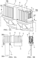
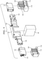
- a battery module 10, or battery pack assembly, is schematically illustrated in Figure 1 .
- the battery module 10 includes multiple battery cells 12 with positive and negative electrical terminals 14a, 14b (generally referred to as "terminal 14").
- the terminals 14 of the various cells 12 are electrically and mechanically connected to one another with bus bar assemblies 16 in a configuration that provides sufficient power for large electrical loads, such as automotive hybrid propulsion systems.
- the terminal 14 is provided by male terminal provided by a quadrangular copper plate. It should be understood that the terminal 14 may be configured differently, for example, as a female terminal. There is a potential shock hazard when the terminal 14 is left exposed. To mitigate the shock hazard when connecting and disconnecting the bus bar assembly 16 from the cells 12, a nonconductive terminal cap 18 is secured to a battery housing 19 by a connection 17 ( Fig. 4 ), for example, snaps. The terminal cap 18 may also be integrally formed with the battery housing 19, for example, during a plastic molding process.
- the bus bar assembly 16 includes a bus bar 36 ( Figs. 2B , 2C and 4 ) substantially enclosed by a nonconductive shroud 20.
- the bus bar 36 has an end 46 provided by a female terminal that mechanically and electrically engages and mates with the male terminal 14 in an assembled condition.
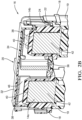
- the nonconductive terminal cap 18 at least partially surrounds the terminal 14.
- a U-shaped perimeter wall 26 circumscribes at least a portion of the terminal 14, for example, on three sides, to provide a gap 44 configured to expose the terminal 14 in order to receive the end 46.
- the terminal cap 18 also has a post 38 that receives the terminal 14 and is arranged interiorly of the perimeter wall 26.
- the terminal 14 has a perimeter edge 40 bounding opposing faces 42 of the terminal 14.
- the post 38 extends outward from a base of the terminal cap 18 and provides an E-shaped configuration with the perimeter wall 26.
- the post 38 surrounds the perimeter edge 40 but leaves at least one of the faces 42 exposed. In this manner, the post 38 shields at least the end of the terminal 14 from contact.
- the perimeter wall 26 extends beyond the terminal 14 and beyond the post 38 to further isolate the terminal 14.
- the perimeter wall 26 and the post 38 cooperate to provide the gap 44 as "finger-proof," that is, preventing undesired contact with the terminal by a technician.
- finger-proof means a configuration that meets the standard set forth in IEC 60529 entitled “Degrees of Protection Provided by Enclosures” and code IP2XB relating to finger Ingress Protection.
- the "test finger” is based upon a solid object 12.5 mm in diameter or more and up to 80 mm long being prevented from entering an enclosure. Furthermore, if a standard test finger 80 mm long and 12 mm in diameter enters the enclosure there will be adequate clearance from live parts, i.e., the terminal. In this manner, the disclosed finger-proof terminal cap 18 prevents a technician from inadvertently touching the terminal 14 with the terminal cap 18 in place, for example, during assembly and/or removal of the bus bar assembly 16 with respect to the cells 12.
- the terminal cap 18 includes a first notch 28, and the shroud 20 includes a second notch 30.
- the shroud 20 is retained to the terminal cap 18 in the assembled condition by a retention feature.
- a first attachment feature 22 on the terminal cap 18, such as a protrusion cooperates with a finger-like second attachment feature 24 on the shroud 20, as best shown in Figure 2B .
- the first and second notches 28, 30 become nested with one another to enclose the terminal 14 and the end 46 and the finger begins to deflect outward as the finger slides over the protrusion.
- the second attachment feature 24 removably engages and interlocks with the first attachment feature 22. Engagement of the first and second attachment features 22, 24 signifies that the desired mechanical and electrical engagement between the terminal 14 and the end 46 has been achieved, that is, the female terminal end 46 has engaged the opposing faces 42 of the male terminal 14 and are safely enclosed. Once coupled, the retention feature prevents inadvertent decoupling of the bus bar 36 from the terminal 14 until the fingers and depressed and the bus bar assembly 16 is pulled away from the terminal cap 18.
- the shroud 20 includes multiple shroud portions cooperating with one another to enclose the bus bar 36, which enables the bus bar to be serviced and the shroud to be reused.
- the multiple shroud portions include first and second shroud portions 32, 34 nested relative to one another in an overlapping relationship.
- the first shroud portion 32 includes a sleeve providing an opening at one end that receives an end of the second shroud portion 34.
- retentions features may be used between the first and second shroud portions 32, 34, a retention feature is not necessarily needed as the shroud portions are held together by the first and second notches 28, 30 when the bus bar assembly 16 is in the assembled condition with respect to the terminal caps 18.
- FIGS 5A-5B illustrate one example variation of the terminal cap 18' configuration.
- the configuration used in the battery module 10 may depend upon the particular connection 17' and housing 19' arrangement as well as the given terminal 14a'.
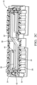
- FIG. 6A-9 Another example bus bar assembly 116 is shown in Figures 6A-9 . Like numerals indicate like elements. Figures 6A, 6B and 9 illustrate one example variation of the terminal cap 18 configuration secured using different housings 19, 19'. Similar to the first bus bar assembly 16, the nonconductive terminal cap 118 at least partially surrounds the terminal 114. There is a U-shaped perimeter wall 126 circumscribing at least a portion of the terminal 114 on three sides to provide the gap 144 exposing the terminal 114 to receive the end 146.
- the post 138 receives the terminal 114 interiorly of the perimeter wall 126.
- the post 138 shields the terminal 114 from contact in a manner similar to that described above in relation to the first bus bar assembly 16.
- the perimeter wall 26 and the post 38 cooperate to provide the gap 44 as "finger-proof,” that is, preventing undesired contact with the terminal by a technician.
- the second bus bar assembly 116 is received interiorly of the perimeter wall 126 instead of in overlapping relationship.
- the shroud 120 is retained to the terminal cap 118 in the assembled condition by a retention feature.
- the first attachment feature on the terminal cap is not illustrated in the Figures, but is provided by a protrusion cooperates with a finger-like second attachment feature 124 on the shroud 20, as best shown in Figures 6A and 9 . As the shroud 20 and end 46 are pushed into the gap 144 during assembly, the end 146 and the finger begins to deflect outward as the finger slides over the protrusion.
- the second attachment feature 124 removably engages and interlocks with the first attachment feature. Engagement of the first and second attachment features signifies that the desired mechanical and electrical engagement between the terminal 114 and the end 146 has been achieved, that is, the female terminal end 46 has engaged the opposing faces 142 of the male terminal 114 and are safely enclosed. Once coupled, the retention feature prevents inadvertent decoupling of the bus bar 136 from the terminal 114 until the fingers and depressed and the bus bar assembly 116 is pulled away from the terminal cap 118.
- the shroud 120 includes multiple shroud portions cooperating with one another to enclose the bus bar 136, which enables the bus bar to be serviced and the shroud to be reused.
- the multiple shroud portions include first and second shroud portions 132, 134 nested relative to one another in an overlapping relationship.
- the second shroud portion 134 is provided on each of opposing sides of the central first shroud portion 132.
- the first shroud portion 132 is provided by cover 50 snap-fit to a base 48.
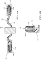
- the first shroud portion 132 includes a sleeve providing an opening at one end that receives a respective end of the second shroud portion 134 using a snap-fit 52 when in the assembled condition. Snap-fits, which include a mating window 54 and a protrusion 56, are used to connect the various shroud pieces.
- the bus bar 136 includes a U-shaped portion 58 received in the first shroud portion 132 to provide a space between opposing ends 46 of the bus bar 136.
- the space accommodates an obstruction 60 arranged between the terminals 14 to enable compact packaging of the battery module 10 with respect to other components.
- a nonconductive terminal cap 18 is provided over a conductive battery cell terminal 14.
- the terminal caps 18 may be provided as loose pieces that are secured to the battery housing 19, if desired, or they may be integrated into the housing.
- the terminal cap 18 at least partially surrounds the terminal 14, which is a male terminal.
- the terminal cap 18 has a perimeter wall 26 configured to circumscribe at least a portion of the terminal 14.
- the terminal 14 is arranged in a post 38 that shields the terminal 14.
- the perimeter wall 26 and the post 38 cooperate to provide a finger-proof gap 44 that exposes the terminal 14.
- a bus bar assembly 16 is provided with a bus bar 36 having an end 46, which is a female terminal.
- a nonconductive shroud 20 encloses the bus bar 36 with the end 46 exposed through the shroud 20.
- the end 46 of the bus bar assembly 16 is pushed into the gap 44 and into engagement with the terminal 14 so that the shroud 20 mates to the terminal cap 18 to enclose the end 46.
- a first attachment feature 22 on the terminal cap 18 interlocks with a second attachment feature 24 on the shroud 20.
- the terminal cap can be secured battery cell about the terminal, rendering the terminal finger-safe.
- the battery module is finger-proof even with the bus bar assemblies disconnected, which allows for safe assembly and handling of the battery module during assembly and servicing of the battery module.
- bus bar assemblies Some additional examples of bus bar assemblies, battery modules and methods of electrically connecting cells of a battery module are as follows:
Landscapes
- Chemical & Material Sciences (AREA)
- Chemical Kinetics & Catalysis (AREA)
- Electrochemistry (AREA)
- General Chemical & Material Sciences (AREA)
- Engineering & Computer Science (AREA)
- Manufacturing & Machinery (AREA)
- Microelectronics & Electronic Packaging (AREA)
- Connection Of Batteries Or Terminals (AREA)
- Connections By Means Of Piercing Elements, Nuts, Or Screws (AREA)
- Multi-Conductor Connections (AREA)
Applications Claiming Priority (2)
| Application Number | Priority Date | Filing Date | Title |
|---|---|---|---|
| US201962865470P | 2019-06-24 | 2019-06-24 | |
| EP20181664.2A EP3758100B1 (de) | 2019-06-24 | 2020-06-23 | Messerklemmen-sammelschiene mit fingerschutz |
Related Parent Applications (1)
| Application Number | Title | Priority Date | Filing Date |
|---|---|---|---|
| EP20181664.2A Division EP3758100B1 (de) | 2019-06-24 | 2020-06-23 | Messerklemmen-sammelschiene mit fingerschutz |
Publications (2)
| Publication Number | Publication Date |
|---|---|
| EP4571995A2 true EP4571995A2 (de) | 2025-06-18 |
| EP4571995A3 EP4571995A3 (de) | 2025-12-24 |
Family
ID=71138544
Family Applications (3)
| Application Number | Title | Priority Date | Filing Date |
|---|---|---|---|
| EP25174198.9A Pending EP4571995A3 (de) | 2019-06-24 | 2020-06-23 | Messerklemen-sammelschiene mit fingerschutz |
| EP20181662.6A Pending EP3758099A1 (de) | 2019-06-24 | 2020-06-23 | Verschraubte sammelschiene mit fingerschutz |
| EP20181664.2A Active EP3758100B1 (de) | 2019-06-24 | 2020-06-23 | Messerklemmen-sammelschiene mit fingerschutz |
Family Applications After (2)
| Application Number | Title | Priority Date | Filing Date |
|---|---|---|---|
| EP20181662.6A Pending EP3758099A1 (de) | 2019-06-24 | 2020-06-23 | Verschraubte sammelschiene mit fingerschutz |
| EP20181664.2A Active EP3758100B1 (de) | 2019-06-24 | 2020-06-23 | Messerklemmen-sammelschiene mit fingerschutz |
Country Status (3)
| Country | Link |
|---|---|
| US (4) | US11870165B2 (de) |
| EP (3) | EP4571995A3 (de) |
| CN (3) | CN119381708A (de) |
Families Citing this family (9)
| Publication number | Priority date | Publication date | Assignee | Title |
|---|---|---|---|---|
| CN113826285B (zh) * | 2019-05-24 | 2024-05-28 | 株式会社自动网络技术研究所 | 端子间连接结构 |
| US10910800B1 (en) * | 2019-10-22 | 2021-02-02 | Rivian Ip Holdings, Llc | Cover assembly for electrical busbar connection |
| DE102021100997B3 (de) * | 2021-01-19 | 2022-04-21 | Te Connectivity Germany Gmbh | Modulverbinder mit wenigstens einer verschieblichen Kontaktanordnung |
| EP4080686A1 (de) * | 2021-04-21 | 2022-10-26 | Rosenberger Hochfrequenztechnik GmbH & Co. KG | Elektrischer steckverbinder, elektrisches verbindungselement und elektrische steckverbindung |
| CN115732830A (zh) * | 2021-08-28 | 2023-03-03 | 莫列斯有限公司 | 电池连接模组及电池组 |
| US11749931B2 (en) * | 2021-12-21 | 2023-09-05 | GM Global Technology Operations LLC | Electrical connection unit for high-voltage battery packs |
| US12482892B2 (en) * | 2022-02-08 | 2025-11-25 | Ford Global Technologies, Llc | Thermal barrier for busbar of traction battery |
| EP4478519A4 (de) * | 2022-05-04 | 2025-05-21 | LG Energy Solution, Ltd. | Batteriesystem, energiespeichersystem damit und darin verwendete schutzabdeckung |
| US20230369724A1 (en) * | 2022-05-10 | 2023-11-16 | Rivian Ip Holdings, Llc | Battery pack apparatus |
Family Cites Families (27)
| Publication number | Priority date | Publication date | Assignee | Title |
|---|---|---|---|---|
| JP2952550B2 (ja) | 1993-09-13 | 1999-09-27 | 矢崎総業株式会社 | バッテリーポスト用接続端子の保護カバー |
| US5804770A (en) * | 1995-09-19 | 1998-09-08 | Sumitomo Wiring Systems, Ltd. | Cover equipped electrical connection device and a cover for an electrical connection device |
| KR0151534B1 (ko) | 1995-10-30 | 1998-08-17 | 이종호 | 유기산 생성이 억제된 대장균 변이주 |
| US6276960B1 (en) | 2000-08-29 | 2001-08-21 | Delphi Technologies, Inc. | Electrical power connector system |
| EP1239506B1 (de) * | 2001-03-07 | 2012-04-25 | Yazaki Corporation | Schutzabdeckung und Sicherungsdose |
| ES2193849B1 (es) * | 2001-07-31 | 2005-03-01 | S.E. Acumulador Tudor, S.A. | Bateria de acumuladores electricos. |
| US7294020B2 (en) | 2005-05-25 | 2007-11-13 | Alcoa Fujikura Ltd. | Canted coil spring power terminal and sequence connection system |
| KR100821859B1 (ko) | 2006-02-09 | 2008-04-11 | 주식회사 엘지화학 | 전극단자 연결부의 안전성이 향상된 전지모듈 |
| EP2109904B1 (de) * | 2007-01-05 | 2012-09-19 | Johnson Controls Saft Advanced Power Solutions LLC | Batteriesystem |
| JP5375440B2 (ja) * | 2009-08-26 | 2013-12-25 | 住友電装株式会社 | 雄型コネクタ及びコネクタ装置 |
| KR101084213B1 (ko) | 2009-11-30 | 2011-11-17 | 삼성에스디아이 주식회사 | 전지 팩 |
| DE102010024519A1 (de) | 2010-06-21 | 2011-12-22 | Tyco Electronics Amp Gmbh | HV-Batteriebrücke |
| JP5803405B2 (ja) | 2011-08-10 | 2015-11-04 | 株式会社オートネットワーク技術研究所 | バスバーカバー、及びカバー付きバスバー |
| JP5934520B2 (ja) * | 2012-02-28 | 2016-06-15 | 矢崎総業株式会社 | バスバーモジュールのケースを覆う絶縁カバー |
| KR20140060633A (ko) | 2012-11-12 | 2014-05-21 | 주식회사 엘지화학 | 버스 바 어셈블리를 포함하는 전지모듈 및 이를 포함하는 전지팩 |
| KR20140094207A (ko) * | 2013-01-21 | 2014-07-30 | 삼성에스디아이 주식회사 | 전지 모듈 |
| US9257772B2 (en) * | 2013-02-08 | 2016-02-09 | Lear Corporation | Electric connector with a lock to retain a terminal within a housing |
| KR102115040B1 (ko) | 2014-03-14 | 2020-05-26 | 엘에스이브이코리아 주식회사 | 고전압 수형 커넥터 |
| US9350127B2 (en) | 2014-03-24 | 2016-05-24 | Ford Global Technologies, Llc | Self-locating busbar assembly and alignment method |
| KR102283792B1 (ko) * | 2014-08-25 | 2021-08-02 | 삼성에스디아이 주식회사 | 이차 전지 모듈 |
| US10396405B2 (en) | 2014-11-10 | 2019-08-27 | Te Connectivity Corporation | Bus bar for a battery connector system |
| US9437860B2 (en) | 2014-11-20 | 2016-09-06 | Ford Global Technologies, Llc | Traction battery assembly having snap-in bus bar module |
| KR102396361B1 (ko) | 2015-08-18 | 2022-05-10 | 삼성에스디아이 주식회사 | 배터리 팩 |
| WO2017054187A1 (en) * | 2015-09-30 | 2017-04-06 | Byd Company Limited | Connector for power batteries, power battery module, power battery pack and vehicle |
| US10516144B2 (en) * | 2016-02-19 | 2019-12-24 | Gs Yuasa International Ltd. | Energy storage apparatus |
| US10355389B2 (en) | 2017-08-01 | 2019-07-16 | Delphi Technologies, Llc | High-current electrical terminal |
| US10003112B1 (en) | 2017-12-01 | 2018-06-19 | GM Global Technology Operations LLC | Battery backplane assembly with integrated bus bar connections and thermal management features |
-
2020
- 2020-05-02 US US16/865,315 patent/US11870165B2/en active Active
- 2020-05-02 US US16/865,316 patent/US11404804B2/en active Active
- 2020-06-23 EP EP25174198.9A patent/EP4571995A3/de active Pending
- 2020-06-23 EP EP20181662.6A patent/EP3758099A1/de active Pending
- 2020-06-23 EP EP20181664.2A patent/EP3758100B1/de active Active
- 2020-06-24 CN CN202411378215.7A patent/CN119381708A/zh active Pending
- 2020-06-24 CN CN202010586768.7A patent/CN112134040B/zh active Active
- 2020-06-24 CN CN202010585815.6A patent/CN112133875B/zh active Active
-
2022
- 2022-06-27 US US17/849,800 patent/US12355166B2/en active Active
-
2023
- 2023-07-26 US US18/226,397 patent/US12272889B2/en active Active
Also Published As
| Publication number | Publication date |
|---|---|
| CN119381708A (zh) | 2025-01-28 |
| CN112134040A (zh) | 2020-12-25 |
| US11404804B2 (en) | 2022-08-02 |
| US11870165B2 (en) | 2024-01-09 |
| US12355166B2 (en) | 2025-07-08 |
| EP4571995A3 (de) | 2025-12-24 |
| US12272889B2 (en) | 2025-04-08 |
| EP3758100A1 (de) | 2020-12-30 |
| US20220328987A1 (en) | 2022-10-13 |
| CN112133875A (zh) | 2020-12-25 |
| EP3758099A1 (de) | 2020-12-30 |
| EP3758100B1 (de) | 2025-06-04 |
| CN112134040B (zh) | 2025-07-04 |
| US20230369787A1 (en) | 2023-11-16 |
| US20200403329A1 (en) | 2020-12-24 |
| US20200403206A1 (en) | 2020-12-24 |
| CN112133875B (zh) | 2024-09-17 |
Similar Documents
| Publication | Publication Date | Title |
|---|---|---|
| US12272889B2 (en) | Battery module and bus bar assembly | |
| CN109565129B (zh) | 电力连接器系统 | |
| JP7637332B2 (ja) | 通電部品,ジャンクションボックス,バスバーモジュール,電池モジュール | |
| US9509096B2 (en) | Manual service disconnects for battery systems | |
| CN107895872B (zh) | 汇流条头座组件 | |
| CN112335115A (zh) | 可插拔模块连接器和用于导电连接至少两个电池模块的方法 | |
| KR102399621B1 (ko) | 배터리 시스템 | |
| CN102396044A (zh) | 高压维修断路组件 | |
| EP3357136B1 (de) | Abgedichtete modulare stromverteilungsvorrichtung | |
| EP4099519B1 (de) | Stecker- und buchsenstromanschlussanordnung, buchen- und steckerstromanschluss | |
| CN114223101A (zh) | 电连接器 | |
| US11975622B2 (en) | Charging inlet assembly having an AC charging module | |
| CN107768206B (zh) | 熔断器适配器组件 | |
| JP3812063B2 (ja) | 蓄電池収容装置 | |
| CN217848382U (zh) | 连接器、高压电连接系统和车辆 | |
| CN215153940U (zh) | 车辆传动装置 | |
| JP2025066665A (ja) | シールド電気導体のためのハウジング、導体装置、およびコネクタ |
Legal Events
| Date | Code | Title | Description |
|---|---|---|---|
| PUAI | Public reference made under article 153(3) epc to a published international application that has entered the european phase |
Free format text: ORIGINAL CODE: 0009012 |
|
| STAA | Information on the status of an ep patent application or granted ep patent |
Free format text: STATUS: THE APPLICATION HAS BEEN PUBLISHED |
|
| AC | Divisional application: reference to earlier application |
Ref document number: 3758100 Country of ref document: EP Kind code of ref document: P |
|
| AK | Designated contracting states |
Kind code of ref document: A2 Designated state(s): AL AT BE BG CH CY CZ DE DK EE ES FI FR GB GR HR HU IE IS IT LI LT LU LV MC MK MT NL NO PL PT RO RS SE SI SK SM TR |
|
| REG | Reference to a national code |
Ref country code: DE Ref legal event code: R079 Free format text: PREVIOUS MAIN CLASS: H01M0050550000 Ipc: H01R0011280000 |
|
| PUAL | Search report despatched |
Free format text: ORIGINAL CODE: 0009013 |
|
| AK | Designated contracting states |
Kind code of ref document: A3 Designated state(s): AL AT BE BG CH CY CZ DE DK EE ES FI FR GB GR HR HU IE IS IT LI LT LU LV MC MK MT NL NO PL PT RO RS SE SI SK SM TR |
|
| RIC1 | Information provided on ipc code assigned before grant |
Ipc: H01R 11/28 20060101AFI20251120BHEP Ipc: H01M 50/505 20210101ALI20251120BHEP Ipc: H01M 50/55 20210101ALI20251120BHEP Ipc: H01R 13/11 20060101ALI20251120BHEP Ipc: H01R 13/506 20060101ALN20251120BHEP |