EP3357136B1 - Abgedichtete modulare stromverteilungsvorrichtung - Google Patents
Abgedichtete modulare stromverteilungsvorrichtung Download PDFInfo
- Publication number
- EP3357136B1 EP3357136B1 EP16852253.0A EP16852253A EP3357136B1 EP 3357136 B1 EP3357136 B1 EP 3357136B1 EP 16852253 A EP16852253 A EP 16852253A EP 3357136 B1 EP3357136 B1 EP 3357136B1
- Authority
- EP
- European Patent Office
- Prior art keywords
- base section
- module
- modules
- cover
- openings
- Prior art date
- Legal status (The legal status is an assumption and is not a legal conclusion. Google has not performed a legal analysis and makes no representation as to the accuracy of the status listed.)
- Active
Links
Images


Classifications
-
- H—ELECTRICITY
- H01—ELECTRIC ELEMENTS
- H01H—ELECTRIC SWITCHES; RELAYS; SELECTORS; EMERGENCY PROTECTIVE DEVICES
- H01H85/00—Protective devices in which the current flows through a part of fusible material and this current is interrupted by displacement of the fusible material when this current becomes excessive
- H01H85/02—Details
- H01H85/20—Bases for supporting the fuse; Separate parts thereof
- H01H85/2045—Mounting means or insulating parts of the base, e.g. covers, casings
-
- B—PERFORMING OPERATIONS; TRANSPORTING
- B60—VEHICLES IN GENERAL
- B60R—VEHICLES, VEHICLE FITTINGS, OR VEHICLE PARTS, NOT OTHERWISE PROVIDED FOR
- B60R16/00—Electric or fluid circuits specially adapted for vehicles and not otherwise provided for; Arrangement of elements of electric or fluid circuits specially adapted for vehicles and not otherwise provided for
- B60R16/02—Electric or fluid circuits specially adapted for vehicles and not otherwise provided for; Arrangement of elements of electric or fluid circuits specially adapted for vehicles and not otherwise provided for electric constitutive elements
- B60R16/023—Electric or fluid circuits specially adapted for vehicles and not otherwise provided for; Arrangement of elements of electric or fluid circuits specially adapted for vehicles and not otherwise provided for electric constitutive elements for transmission of signals between vehicle parts or subsystems
- B60R16/0238—Electrical distribution centers
-
- B—PERFORMING OPERATIONS; TRANSPORTING
- B60—VEHICLES IN GENERAL
- B60R—VEHICLES, VEHICLE FITTINGS, OR VEHICLE PARTS, NOT OTHERWISE PROVIDED FOR
- B60R16/00—Electric or fluid circuits specially adapted for vehicles and not otherwise provided for; Arrangement of elements of electric or fluid circuits specially adapted for vehicles and not otherwise provided for
- B60R16/02—Electric or fluid circuits specially adapted for vehicles and not otherwise provided for; Arrangement of elements of electric or fluid circuits specially adapted for vehicles and not otherwise provided for electric constitutive elements
- B60R16/023—Electric or fluid circuits specially adapted for vehicles and not otherwise provided for; Arrangement of elements of electric or fluid circuits specially adapted for vehicles and not otherwise provided for electric constitutive elements for transmission of signals between vehicle parts or subsystems
- B60R16/0239—Electronic boxes
-
- H—ELECTRICITY
- H01—ELECTRIC ELEMENTS
- H01H—ELECTRIC SWITCHES; RELAYS; SELECTORS; EMERGENCY PROTECTIVE DEVICES
- H01H85/00—Protective devices in which the current flows through a part of fusible material and this current is interrupted by displacement of the fusible material when this current becomes excessive
- H01H85/02—Details
- H01H85/20—Bases for supporting the fuse; Separate parts thereof
- H01H2085/2085—Holders for mounting a fuse on a printed circuit
-
- H—ELECTRICITY
- H01—ELECTRIC ELEMENTS
- H01H—ELECTRIC SWITCHES; RELAYS; SELECTORS; EMERGENCY PROTECTIVE DEVICES
- H01H2223/00—Casings
- H01H2223/002—Casings sealed
-
- H—ELECTRICITY
- H01—ELECTRIC ELEMENTS
- H01H—ELECTRIC SWITCHES; RELAYS; SELECTORS; EMERGENCY PROTECTIVE DEVICES
- H01H85/00—Protective devices in which the current flows through a part of fusible material and this current is interrupted by displacement of the fusible material when this current becomes excessive
- H01H85/0013—Means for preventing damage, e.g. by ambient influences to the fuse
- H01H85/0021—Means for preventing damage, e.g. by ambient influences to the fuse water or dustproof devices
- H01H85/0026—Means for preventing damage, e.g. by ambient influences to the fuse water or dustproof devices casings for the fuse and its base contacts
Definitions
- the disclosure relates generally to a power distribution assembly and, more particularly, to a sealed modular fuse box system.
- Components such as fuses, relays, diodes, and the like, are used in automobiles to provide a connection between the battery and various components, such as the starter, generator, and so forth.
- Fuses may be provided in a fuse assembly that may be connected to the automobile battery. Such an assembly is shown in e.g. US 649 731 B .
- the fuses may be individually inserted frictionally into a pair of projections, which are provided by a terminal.
- the terminal is held fixed by upper and lower press-fit layers.
- An upper housing of a housing assembly defines apertures, wherein the projections extend into the apertures so that an operator may place a fuse into the pair of projections.
- power distribution assemblies including multiple components and multi-part housings are expensive to manufacture and assemble, and lack scalable customization to meet the needs of smaller applications.
- One exemplary approach in accordance with the present disclosure may include an apparatus having a module extending into an interior cavity of a housing assembly through an opening formed in a base section of the housing assembly, the module including a component grid.
- the apparatus may further include a mechanical sealing element disposed along a surface of the module to provide a seal between the module and the base section defining the opening.
- FIG. 1 Another exemplary approach in accordance with the present disclosure may include a modular power distribution apparatus having a housing assembly including a base section coupled to a cover, and a set of modules extending into an interior cavity of the housing assembly through one or more openings formed in the base section.
- Each of the set of modules may include a component grid disposed at a first end.
- the modular power distribution apparatus may further include a mechanical sealing element disposed along one or more sidewalls of each of the set of modules to provide a seal between each of the set of modules and the base section defining each of the one or more openings.
- a modular power system having a housing assembly including a base section and a cover.
- the base section may include a base wall including a plurality of openings, and an inner wall extending substantially perpendicularly from the base wall, wherein the inner wall is releasably coupled to the cover.
- the modular power system may further include a plurality of modules extending into an interior cavity of the housing assembly through the plurality of openings of the base wall.
- Each of the set of modules may include a component grid disposed at a first end, and a mechanical sealing element disposed along one or more sidewalls of each of the set of modules, the mechanical sealing element in contact with the base wall.
- top,” “bottom,” “upper,” “lower,” “vertical,” “horizontal,” “lateral,” and “longitudinal” will be used herein to describe the relative placement and orientation of these components and their constituent parts, each with respect to the geometry and orientation of a sensor apparatus and/or housing assembly as they appear in FIGS. 1-5 .
- Said terminology will include the words specifically mentioned, derivatives thereof, and words of similar import.
- an apparatus may include a module extending into an interior cavity of a housing assembly through an opening formed in a base section of the housing assembly.
- the module may include a component grid at one end for receiving one or more components (e.g., fuses, relays, circuit breakers, diodes, etc.), and a wiring alignment cover at an opposite end operable with a terminal.
- the apparatus may further include a mechanical sealing element disposed along one or more surfaces of the module to provide a seal between the module and the base section defining the opening.
- a plurality of modules may be disposed within a plurality of openings formed in the base section.
- the apparatus may include a bracket configured to releasably connect the base section and the cover.
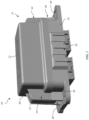
- the exemplary apparatus 10 includes a housing assembly 14 having a base section 18 coupled to a cover 22, the cover 22 removably connected to the base section 18 and covering the circuit protection components therein.
- the cover 22 can be removed, for example, to replace an opened fuse or to inspect the power distribution grid.
- the cover 22 includes a seal that prevents dust, moisture and other contaminants from reaching the circuit protection devices.
- the cover 22 can snap-fit to the base section 18 and/or include one or more latching mechanisms to secure the cover to the housing releasably, as will be further described herein.
- the cover 22 is threaded onto the base section 18 and can include a spring seal that provides a tensile force against the cover 22, which tends to hold the cover in a tight, threaded relationship with the housing even when the vehicle is moving and creating vibrations that could otherwise loosen the cover 22.
- the spring mechanism can also provide a seal between the cover 22 and the base section 18.
- the cover 22 may also include means to further facilitate grasping and removal, such as tabs, projections, recesses, etc.
- the base section 18 may include a set of interlocking features 26 for mounting multiple housing assemblies together, as well as one or more mounting apertures 30.
- the housing assembly 14 may be made of an insulating material, such as plastic, which is molded to form a demonstrated shape.
- the base section 18 and the cover 22 can be made of the same or different materials, such as an insulating plastic, e.g., nylon, glass-filled nylon, polyester and polycarbonate.
- the apparatus 10 further includes one or more brackets 34 coupled to a pin 38 ( FIG. 3 ) of the base section 18, wherein the brackets 34 are configured to releasably connect the base section 18 to the cover 22.
- the brackets 34 pivot about an axis defined by the pin 38 to move a top section 42 of each bracket 34 towards/away from the cover 22.
- the brackets 34 may rotate and extend away from the cover 22. Then, as the cover 22 is positioned onto the base section 18, a first set of support structures 44 of the cover 22 are positioned atop and generally align with a second set of support structures 46 of the base section 18.
- the first set of support structures 44 and the second set of support structures 46 extend perpendicularly from an end wall surface 50 of the cover 22 and an end wall surface 52 of the base section 18, respectively. Furthermore, as shown, a cross-brace 56 extends between the first set of support structures 44 of the cover 22 and includes a tab 58 configured to engage a protrusion 60 of the top section 42 of each bracket 34 to secure the cover 22 to the base section 18.
- the apparatus 10 may further include a sealing strip 62 positioned between the cover 22 and the base section 18 to provide a seal therebetween.
- the sealing strip 62 is an elastomer configured as a plurality of ridges and groves to provide a mechanical seal between an upper rim 64 of the base section 18 and a lower shoulder 66 of the cover 22.
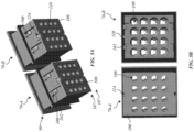
- the apparatus 10 of the present disclosure includes one or more modules 70A-B, which provide customizable electrical connections.
- the modules 70A-B allow a snap-together assembly with the base section 18 of the housing assembly 14 to accommodate different bussed or non-bussed configurations and, therefore, provide a wide variety of pole variations for a specific application.
- FIGS. 2-4 demonstrate a pair of modules 70A-B extending through a corresponding pair of openings, the apparatus 10 is scalable, and therefore may accommodate a greater number of modules and openings in other embodiments.
- the apparatus 10 includes one or more modules 70A-B extending into an interior cavity 74 of the housing assembly 14 though one or more corresponding openings 76A-B formed in the base section 18 of the housing assembly 14.
- the base section 18 includes a base wall 78 having openings 76A-B formed therein, the openings 76A-B configured to receive the modules 70A-B.
- the openings 76A-B may be separated by a framing element 77 and include a first ledge 82 for engaging a flange 84 that extends laterally from a sidewall 86 of each module 70A-B.
- Each of the openings 76A-B may further define a second ledge 88 for engaging a mechanical sealing element 90 disposed along one or more sidewalls of the modules 70A-B. As shown, when positioned within the openings 76A-B, the first ledge 82 is in abutment with the flange 84, the second ledge 88 is in abutment with the mechanical sealing element 90, and the modules 70A-B are substantially planar with a surface 92 within the interior cavity 74.
- each module 70A-B includes the mechanical sealing element 90 disposed along the sidewall 86 to provide a seal between the modules 70A-B and the base section 18 defining respective openings 76A-B.
- the mechanical sealing element 90 includes a gasket 94 (e.g., an elastomer) in contact with a ridge 96, wherein the gasket 94 and the ridge 96 extend perpendicularly from each side of the modules 70A-B to form a perimeter around each of the modules 70A-B.
- the gasket 94 is positioned between the ridge 96 and the second ledge 88 of each opening 76A-B to form a seal therebetween.
- each the modules 70A-B includes a component grid 98 disposed at a first end 99 thereof.
- the component grid 98 may be coupled to each module 70A-B and positioned within the openings 76A-B such that the component grid 98 is exposed to the interior cavity 74 of the base section 18 and is substantially planar with the surface 92.
- the component grid 98 may include a matrix of apertures that form a plurality of footprints for a plurality of components, such as fuses or circuit protection devices (overcurrent or overvoltage), that are plugged into the component grid 98 of the apparatus 10.
- the apertures in the component grid 98 can form a plurality of the same types of fuses. Alternatively, the apertures form different footprints for different types of component footprints. In one embodiment, the apertures of the component grid 98 form footprints for a plurality of male blade type fuses, such as MINI ® fuses. In another embodiment, the apertures may form footprints for female cartridge fuses (e.g., JCASE TM fuses provided by the assignee of the present disclosure) or larger type fuses (e.g., ATO ® fuses or MAXI ® fuses, both provided by the assignee of the present disclosure). Components may be micro-relays, while other components may be ISO/power relays. The apparatus 10 is accordingly not limited to fuse operation.
- the fuses and other components are illustrated for automotive uses, such as for cars, trucks, motorcycles, boats, wave-runners, all-terrain vehicles and other types of sports vehicles or others listed above.
- teachings of the present disclosure and the benefits and advantages of the apparatus 10 are not limited to vehicle type applications.
- the modules 70A-B may be bussed and/or unbussed.
- one or more of the modules 70A-B may operate without a bussing element (e.g., a bus bar).
- a bussing element e.g., a bus bar.
- the elimination of internal bussing may allow greater circuitry customization using direct wire-to-component connections.
- unbussed modules may accommodate one or more of the following component configurations: (8) MINI ® ; (6) ATO ® ; (3) MAXI ® ; (4) JCASE TM ; (1) ISO form C MINI ® relay and (2) ATO ® ; (1) ISO power relay; (2) ISO micro form A and (2) ATO ® , (2) MAXI ® and (2) ATO ® ; (2) Delphi ® Metri-Pack 280 series form C relays and (2) Delphi ® Metri-Pack 280 series form A terminals; and (4) Delphi ® Metri-Pack 280 series form A terminals and (4) MINI ® .
- one or more of the modules 70A-B include a bussing element, such as a bus bar, connected thereto.
- bussed modules may accommodate one or more of the following component configurations: (8) MINI ® ; 6 ATO ® ; (4) JCASE TM ; (1) ISO power relay form A and (1) MAXI ® ; (2) ISO MINI ® form C and (2) ATO ® ; (1) ISO power relay form A and (2) JCASE TM ; (2) Delphi ® Metri-Pack 280 series form C terminals and (2) series form A terminals; and (4) Delphi ® Metri-Pack 280 series form A terminals and (4) MINI ® .
- the bus bar may be made of any suitable electrically conductive material, for example, a material capable of carrying relatively high currents.
- a suitable material is C1100 alloy, which is 99.9% pure copper with 1 ⁇ 2 hard temper.
- the bus bar includes one or more heat sinks.
- each of the modules 70A-B includes one or more module fasteners 100 that releasably connect to corresponding elements (not shown) along the interior of the openings 76A-B.
- each module fastener 100 may be a snap-fit connector having a retaining projection 102 that is received in a sidewall aperture of the openings 76A-B.
- the snap-fit connector includes one or more tongues extending beneath leading edges of adjacent sections and received in complementary slots (not shown) inside grooves of mating sections along the sidewalls of openings 76A-B so that the mating ends of adjacent sections slightly overlap one another and form a secure, structurally stable fit with one another.
- the module fasteners 100 provide a secure resistance fit that facilitates assembly and disassembly of the modules 70A-B by hand and without employing tools.
- each of the modules 70A-B is coupled with a wiring alignment cover 106 at a second end 107 thereof, the wiring alignment cover 106 disposed external to the base section 18.
- the wiring alignment cover 106 may be a terminal position assurance lock (TPA), which provides secondary locking protection of wire leads (not shown) inserted through a plurality of openings 108 therein, which are substantially aligned with a plurality of openings 109 ( FIG. 5B ) in the modules 70A-B.
- TPA terminal position assurance lock
- Module 70B of FIG. 5B is shown without the wiring alignment cover 106 for the sake of explanation.
- the wiring alignment cover 106 may snap onto the bottom of the modules 70A-B after wires are installed, and do not interfere with any cable seals. As shown, the wiring alignment cover 106 is secured to each of the modules 70A-B via one or more alignment cover fasteners 110 disposed along a sidewall of the modules 70A-B, wherein the alignment cover fasteners 110 are configured to releasably connect the wiring alignment cover 106 and each of the modules 70A-B.
- each alignment cover fastener 110 is a snap-fit connector having a retaining projection that is received in an aperture 114.
- a plurality of terminals may be coupled to the modules 70A-B at the second end 107, so that the terminals extend through the modules 70A-B via the plurality of openings 76A-B and directly connect to the components of the component grid 98 through the base wall 78 of the base section 18.
- the modules 70A-B may additionally receive any combination of cable seals and/or cavity plugs in addition to the terminals.
- the terminals may include a male blade-type fuse (e.g., a MINI ® fuse), which includes a pair of blade terminals, each of which press fits into one of the fuse mounting terminals. For each fuse, one of the terminals may connect to a trace that extends to a load within the vehicle. Other terminals may connects electrically to a trace that extends to a common electrical connection.
- the modules 70A-N are operable with terminals utilizing internationally standardized male blade sizes, allowing for flexibility in design.
- blade sizes may range from 1.5 mm to 8 mm with current capability ranging from 14 to 60 amps.
- the terminals may be designed to be compatible with processing techniques such as automated pull-to-seat and push-to-seat assembly, dual-stage crimping, load cell crimp inspection and automated part identification and orientation.
- the terminals may be sealed to reduce exposure to extreme temperatures, chemicals, and abrasion.
- the terminals may be mounting terminals (e.g., having a tuning fork like configuration) that may or may not be soldered (e.g., wave soldered) to a printed circuit board (PCB).
- the terminals are surface-mounted to the PCB. In such case, the terminals do not extend through the PCB.
- the PCB provides the circuit routing between the fuses and terminal connections.
- the PCB includes traces that run from the fuse mounting terminals to the connector terminals, stud connectors, etc.
- the PCB may be made of FR-4 material but can alternatively be ceramic if a more rigid material is needed.
- the PCB can be single or multilayered and is customized as desired by the customer.
- the PCB can provide a wider trace that serves as a buss bar or common connection for the fuse mounting terminals and connector terminals.
- the PCB can also hold other types of circuit protection, such as overvoltage protection in the form of medal oxide varistors ("MOVs"), diodes, and thyristors.
- MOVs medal oxide varistors
- the overvoltage protection devices can be used for example to protect low operating voltage or signal level devices placed in the automobile.
- the overvoltage protection devices can be mounted on a same side of the PCB as the fuses or be located on the opposite or bottom side of the PCB.
Landscapes
- Engineering & Computer Science (AREA)
- Mechanical Engineering (AREA)
- Casings For Electric Apparatus (AREA)
- Connection Or Junction Boxes (AREA)
- Connector Housings Or Holding Contact Members (AREA)
- Fuses (AREA)
- Gasket Seals (AREA)
Claims (7)
- Einrichtung (10), umfassend:ein Modul (70A, 70B), das sich in einen Innenhohlraum (74) einer Gehäuseanordnung (14) durch eine Öffnung einer Vielzahl von Öffnungen (76A, 76B) erstreckt, die in einem Basisabschnitt (18) der Gehäuseanordnung (14) ausgebildet sind, wobei das Modul (70A, 70B) ein Komponentengitter (98) einschließt; undein mechanisches Abdichtungselement (90), das entlang einer Oberfläche (92) des Moduls (70A, 70B) angeordnet ist, um eine Abdichtung zwischen dem Modul (70A, 70B) und dem Basisabschnitt (18), der die Öffnung definiert, bereitzustellen, wobei die Vielzahl von Öffnungen (76A, 76B) durch ein Rahmenelement (77) getrennt ist, das sich über den Innenhohlraum (74) erstreckt,wobei das mechanische Abdichtungselement (90) eine Dichtung (94) umfasst, die an einen Grat (96) angrenzt, wobei sich der Grat (96) von der Oberfläche des Moduls (70A, 70B) erstreckt.
- Einrichtung (10) nach Anspruch 1, ferner umfassend eine Halterung (34), die mit dem Basisabschnitt (18) gekoppelt ist, wobei die Halterung (34) den Basisabschnitt (18) und eine Abdeckung (22) der Gehäuseanordnung (14) lösbar verbindet.
- Einrichtung (10) nach Anspruch 1, ferner umfassend eine mit dem Modul (70A, 70B) gekoppelte Verdrahtungsausrichtungsabdeckung (106).
- Einrichtung (10) nach Anspruch 3, wobei das Modul (70A, 70B) einen Ausrichtungsabdeckungsbefestiger (110) einschließt, der die Verdrahtungsausrichtungsabdeckung (106) mit dem Modul (70A, 70B) lösbar verbindet.
- Einrichtung (10) nach Anspruch 1, wobei das Modul (70A, 70B) einen Modulbefestiger (100) umfasst, der den Basisabschnitt (18) und das Modul (70A, 70B) lösbar verbindet.
- Einrichtung (10) nach Anspruch 1, ferner umfassend einen Vorsprung des Basisabschnitts (18), der an das mechanische Abdichtungselement (90) angrenzt.
- Einrichtung (10) nach Anspruch 1, ferner umfassend eine Vielzahl von Modulen (70A, 70B), die sich durch die Vielzahl von Öffnungen (76A, 76B), die in einer Basiswand (78) des Basisabschnitts (18) ausgebildet sind, in den Innenhohlraum (74) des Basisabschnitts (18) erstrecken.
Applications Claiming Priority (2)
| Application Number | Priority Date | Filing Date | Title |
|---|---|---|---|
| US14/872,325 US9911565B2 (en) | 2015-10-01 | 2015-10-01 | Sealed modular power distribution apparatus |
| PCT/US2016/047710 WO2017058382A1 (en) | 2015-10-01 | 2016-08-19 | Sealed modular power distribution apparatus |
Publications (3)
| Publication Number | Publication Date |
|---|---|
| EP3357136A1 EP3357136A1 (de) | 2018-08-08 |
| EP3357136A4 EP3357136A4 (de) | 2019-05-22 |
| EP3357136B1 true EP3357136B1 (de) | 2025-05-21 |
Family
ID=58424165
Family Applications (1)
| Application Number | Title | Priority Date | Filing Date |
|---|---|---|---|
| EP16852253.0A Active EP3357136B1 (de) | 2015-10-01 | 2016-08-19 | Abgedichtete modulare stromverteilungsvorrichtung |
Country Status (7)
| Country | Link |
|---|---|
| US (1) | US9911565B2 (de) |
| EP (1) | EP3357136B1 (de) |
| JP (1) | JP2018533814A (de) |
| KR (1) | KR102205733B1 (de) |
| CN (1) | CN108141014B (de) |
| ES (1) | ES3034900T3 (de) |
| WO (1) | WO2017058382A1 (de) |
Families Citing this family (8)
| Publication number | Priority date | Publication date | Assignee | Title |
|---|---|---|---|---|
| US10040412B2 (en) * | 2016-05-10 | 2018-08-07 | Deere & Company | Utility vehicle power distribution module |
| CN111371004B (zh) * | 2018-12-25 | 2022-03-29 | 李尔公司 | 防止不正确安装的电气组件 |
| US10483729B1 (en) * | 2019-01-24 | 2019-11-19 | Littelfuse, Inc. | Vented power distribution housing |
| CN110103848A (zh) * | 2019-04-24 | 2019-08-09 | 上海沪工汽车电器有限公司 | 一种车用中央电气接线盒内部嵌入式电池安全开关固定结构 |
| KR102691629B1 (ko) * | 2019-07-11 | 2024-08-05 | 수조우 리텔퓨즈 오브이에스 컴퍼니 리미티드 | 집적된 솔레노이드들을 가지는 퓨즈 장치 |
| JP7198511B2 (ja) * | 2020-01-27 | 2023-01-04 | 太平洋精工株式会社 | ヒューズ |
| JP7284135B2 (ja) * | 2020-10-12 | 2023-05-30 | 矢崎総業株式会社 | 電気接続箱の組付け構造及び電気接続箱の組付け方法 |
| CN112849420B (zh) * | 2021-02-03 | 2022-12-13 | 中国工程物理研究院总体工程研究所 | 一种分区域分舱密封结构 |
Citations (2)
| Publication number | Priority date | Publication date | Assignee | Title |
|---|---|---|---|---|
| US20080057758A1 (en) * | 2006-08-30 | 2008-03-06 | Tyco Electronics Corporation | Electrical connector with ESD protection |
| US7649731B2 (en) * | 2007-01-31 | 2010-01-19 | Tyco Electronics Corporation | Power distribution module using buss bar |
Family Cites Families (19)
| Publication number | Priority date | Publication date | Assignee | Title |
|---|---|---|---|---|
| US4781600A (en) * | 1986-06-25 | 1988-11-01 | Yazaki Corporation | Junction box and a process of assembling the same |
| US4772759A (en) * | 1987-09-23 | 1988-09-20 | United Technologies Automotive, Inc. | Ventilated splash resistant electrical component housing |
| US5777843A (en) | 1996-07-12 | 1998-07-07 | Yazaki Corporation | Power distribution box and housing assembly |
| US5752856A (en) * | 1996-07-30 | 1998-05-19 | The Whitaker Corporation | Sealed fuse connector |
| WO1998018180A1 (en) | 1996-10-24 | 1998-04-30 | Thomas & Betts International, Inc. | Power distribution center |
| US6027360A (en) * | 1998-06-10 | 2000-02-22 | Yazaki Corporation | Junction block bracket for floating connector attachment |
| US6431880B1 (en) | 1998-06-22 | 2002-08-13 | Cooper Technologies | Modular terminal fuse block |
| US6869292B2 (en) * | 2001-07-31 | 2005-03-22 | Fci Americas Technology, Inc. | Modular mezzanine connector |
| US6850421B2 (en) * | 2002-04-01 | 2005-02-01 | Tyco Electronics Corporation | Fuse relay box apparatus, methods and articles of manufacture |
| DE10307944B4 (de) * | 2003-02-25 | 2005-08-18 | Berthold Sichert Gmbh | Überstülpbarer Verteilerschrank |
| US7396262B2 (en) | 2004-12-10 | 2008-07-08 | Cooper Technologies Company | Sealed compact power distribution module |
| US7591653B2 (en) * | 2006-09-08 | 2009-09-22 | Aees, Inc. | Modular power distribution center |
| US7531270B2 (en) * | 2006-10-13 | 2009-05-12 | Enerdel, Inc. | Battery pack with integral cooling and bussing devices |
| JP2009131088A (ja) * | 2007-11-26 | 2009-06-11 | Furukawa Electric Co Ltd:The | 電気接続箱 |
| PL2079091T3 (pl) * | 2008-01-10 | 2014-07-31 | Schneider Electric Ind Sas | Obudowa wyzwalacza elektronicznego dla wyłącznika samoczynnego, elektroniczne urządzenie rozłączające i sposób montażu |
| US7786386B2 (en) * | 2008-04-15 | 2010-08-31 | Gm Global Technology Operations, Inc. | High-voltage vehicle component connection method and apparatus |
| US8119892B2 (en) | 2010-06-17 | 2012-02-21 | Voyage-Air Guitar Inc. | Latch for travel guitar with hinged neck |
| JP5423654B2 (ja) * | 2010-02-05 | 2014-02-19 | 株式会社デンソー | 電力変換装置 |
| JP2015521352A (ja) * | 2012-05-30 | 2015-07-27 | デルフィ・インターナショナル・オペレーションズ・ルクセンブルク・エス・アー・エール・エル | 電気デバイスおよびワイヤを具備した相互接続アセンブリならびに相互接続方法 |
-
2015
- 2015-10-01 US US14/872,325 patent/US9911565B2/en active Active
-
2016
- 2016-08-19 CN CN201680056704.8A patent/CN108141014B/zh active Active
- 2016-08-19 WO PCT/US2016/047710 patent/WO2017058382A1/en not_active Ceased
- 2016-08-19 JP JP2018517128A patent/JP2018533814A/ja active Pending
- 2016-08-19 ES ES16852253T patent/ES3034900T3/es active Active
- 2016-08-19 KR KR1020187011974A patent/KR102205733B1/ko active Active
- 2016-08-19 EP EP16852253.0A patent/EP3357136B1/de active Active
Patent Citations (2)
| Publication number | Priority date | Publication date | Assignee | Title |
|---|---|---|---|---|
| US20080057758A1 (en) * | 2006-08-30 | 2008-03-06 | Tyco Electronics Corporation | Electrical connector with ESD protection |
| US7649731B2 (en) * | 2007-01-31 | 2010-01-19 | Tyco Electronics Corporation | Power distribution module using buss bar |
Also Published As
| Publication number | Publication date |
|---|---|
| ES3034900T3 (en) | 2025-08-26 |
| WO2017058382A1 (en) | 2017-04-06 |
| CN108141014B (zh) | 2020-12-04 |
| JP2018533814A (ja) | 2018-11-15 |
| US20170098523A1 (en) | 2017-04-06 |
| EP3357136A4 (de) | 2019-05-22 |
| CN108141014A (zh) | 2018-06-08 |
| US9911565B2 (en) | 2018-03-06 |
| KR102205733B1 (ko) | 2021-01-21 |
| KR20180057709A (ko) | 2018-05-30 |
| EP3357136A1 (de) | 2018-08-08 |
Similar Documents
| Publication | Publication Date | Title |
|---|---|---|
| EP3357136B1 (de) | Abgedichtete modulare stromverteilungsvorrichtung | |
| JP5702314B2 (ja) | 切り替え可能なヒューズ付き配電ブロック | |
| CN104283114B (zh) | 具有一体的连接器的环境密封的电气罩壳组件 | |
| US20070270045A1 (en) | Sealed compact power distribution module | |
| JP5610648B2 (ja) | ヒューズ付きコネクタ組立体 | |
| US7396262B2 (en) | Sealed compact power distribution module | |
| US8488303B2 (en) | Electrical distribution center | |
| EP1197397B1 (de) | Elektrische Kraftfahrzeugverbindungsdose | |
| GB2339344A (en) | Power distribution block | |
| EP3758099A1 (de) | Verschraubte sammelschiene mit fingerschutz | |
| EP3687012A1 (de) | Belüftetes leistungsverteilungsgehäuse | |
| US7355502B1 (en) | Direct relay connection to a fusible link | |
| JP7640379B2 (ja) | 電源ブロック | |
| CN218351808U (zh) | 用于电气设备的接线端子和电气设备 | |
| US11728603B2 (en) | Method for sealed fuse holder with ISO micro relay | |
| EP1548786B1 (de) | Sicherungsanschlussanordnung für Stromschiene und elektrisches Verbindungsgehäuse mit einer solchen Anordnung | |
| WO2024127804A1 (ja) | ヒューズ | |
| JP2025008362A (ja) | ヒューズユニット | |
| JP2004072982A (ja) | 電気接続箱のキャビティ構造 |
Legal Events
| Date | Code | Title | Description |
|---|---|---|---|
| STAA | Information on the status of an ep patent application or granted ep patent |
Free format text: STATUS: THE INTERNATIONAL PUBLICATION HAS BEEN MADE |
|
| PUAI | Public reference made under article 153(3) epc to a published international application that has entered the european phase |
Free format text: ORIGINAL CODE: 0009012 |
|
| STAA | Information on the status of an ep patent application or granted ep patent |
Free format text: STATUS: REQUEST FOR EXAMINATION WAS MADE |
|
| 17P | Request for examination filed |
Effective date: 20180426 |
|
| AK | Designated contracting states |
Kind code of ref document: A1 Designated state(s): AL AT BE BG CH CY CZ DE DK EE ES FI FR GB GR HR HU IE IS IT LI LT LU LV MC MK MT NL NO PL PT RO RS SE SI SK SM TR |
|
| AX | Request for extension of the european patent |
Extension state: BA ME |
|
| DAV | Request for validation of the european patent (deleted) | ||
| DAX | Request for extension of the european patent (deleted) | ||
| RIN1 | Information on inventor provided before grant (corrected) |
Inventor name: SCHWARTZ, GEOFFREY Inventor name: KAUFMAN, JUSTIN Inventor name: MCWHINNEY, MATT Inventor name: SCRIBNER, DANA |
|
| A4 | Supplementary search report drawn up and despatched |
Effective date: 20190426 |
|
| RIC1 | Information provided on ipc code assigned before grant |
Ipc: H02B 1/26 20060101AFI20190418BHEP Ipc: H01R 9/24 20060101ALI20190418BHEP Ipc: H05K 5/06 20060101ALI20190418BHEP Ipc: B60R 16/023 20060101ALI20190418BHEP |
|
| STAA | Information on the status of an ep patent application or granted ep patent |
Free format text: STATUS: EXAMINATION IS IN PROGRESS |
|
| 17Q | First examination report despatched |
Effective date: 20220725 |
|
| GRAP | Despatch of communication of intention to grant a patent |
Free format text: ORIGINAL CODE: EPIDOSNIGR1 |
|
| STAA | Information on the status of an ep patent application or granted ep patent |
Free format text: STATUS: GRANT OF PATENT IS INTENDED |
|
| INTG | Intention to grant announced |
Effective date: 20250203 |
|
| P01 | Opt-out of the competence of the unified patent court (upc) registered |
Free format text: CASE NUMBER: APP_10358/2025 Effective date: 20250302 |
|
| GRAS | Grant fee paid |
Free format text: ORIGINAL CODE: EPIDOSNIGR3 |
|
| GRAA | (expected) grant |
Free format text: ORIGINAL CODE: 0009210 |
|
| STAA | Information on the status of an ep patent application or granted ep patent |
Free format text: STATUS: THE PATENT HAS BEEN GRANTED |
|
| AK | Designated contracting states |
Kind code of ref document: B1 Designated state(s): AL AT BE BG CH CY CZ DE DK EE ES FI FR GB GR HR HU IE IS IT LI LT LU LV MC MK MT NL NO PL PT RO RS SE SI SK SM TR |
|
| REG | Reference to a national code |
Ref country code: GB Ref legal event code: FG4D |
|
| REG | Reference to a national code |
Ref country code: CH Ref legal event code: EP |
|
| REG | Reference to a national code |
Ref country code: DE Ref legal event code: R096 Ref document number: 602016092340 Country of ref document: DE |
|
| REG | Reference to a national code |
Ref country code: IE Ref legal event code: FG4D |
|
| REG | Reference to a national code |
Ref country code: SE Ref legal event code: TRGR |
|
| PGFP | Annual fee paid to national office [announced via postgrant information from national office to epo] |
Ref country code: GB Payment date: 20250626 Year of fee payment: 10 |
|
| PGFP | Annual fee paid to national office [announced via postgrant information from national office to epo] |
Ref country code: FR Payment date: 20250623 Year of fee payment: 10 |
|
| PGFP | Annual fee paid to national office [announced via postgrant information from national office to epo] |
Ref country code: SE Payment date: 20250610 Year of fee payment: 10 |
|
| PGFP | Annual fee paid to national office [announced via postgrant information from national office to epo] |
Ref country code: NL Payment date: 20250704 Year of fee payment: 10 |
|
| REG | Reference to a national code |
Ref country code: ES Ref legal event code: FG2A Ref document number: 3034900 Country of ref document: ES Kind code of ref document: T3 Effective date: 20250826 |
|
| REG | Reference to a national code |
Ref country code: NL Ref legal event code: FP |
|
| PG25 | Lapsed in a contracting state [announced via postgrant information from national office to epo] |
Ref country code: FI Free format text: LAPSE BECAUSE OF FAILURE TO SUBMIT A TRANSLATION OF THE DESCRIPTION OR TO PAY THE FEE WITHIN THE PRESCRIBED TIME-LIMIT Effective date: 20250521 Ref country code: PT Free format text: LAPSE BECAUSE OF FAILURE TO SUBMIT A TRANSLATION OF THE DESCRIPTION OR TO PAY THE FEE WITHIN THE PRESCRIBED TIME-LIMIT Effective date: 20250922 |
|
| PGFP | Annual fee paid to national office [announced via postgrant information from national office to epo] |
Ref country code: ES Payment date: 20250909 Year of fee payment: 10 |
|
| PGFP | Annual fee paid to national office [announced via postgrant information from national office to epo] |
Ref country code: DE Payment date: 20250624 Year of fee payment: 10 |
|
| REG | Reference to a national code |
Ref country code: LT Ref legal event code: MG9D |
|
| PG25 | Lapsed in a contracting state [announced via postgrant information from national office to epo] |
Ref country code: NO Free format text: LAPSE BECAUSE OF FAILURE TO SUBMIT A TRANSLATION OF THE DESCRIPTION OR TO PAY THE FEE WITHIN THE PRESCRIBED TIME-LIMIT Effective date: 20250821 Ref country code: GR Free format text: LAPSE BECAUSE OF FAILURE TO SUBMIT A TRANSLATION OF THE DESCRIPTION OR TO PAY THE FEE WITHIN THE PRESCRIBED TIME-LIMIT Effective date: 20250822 |
|
| PG25 | Lapsed in a contracting state [announced via postgrant information from national office to epo] |
Ref country code: PL Free format text: LAPSE BECAUSE OF FAILURE TO SUBMIT A TRANSLATION OF THE DESCRIPTION OR TO PAY THE FEE WITHIN THE PRESCRIBED TIME-LIMIT Effective date: 20250521 |
|
| PGFP | Annual fee paid to national office [announced via postgrant information from national office to epo] |
Ref country code: IT Payment date: 20250722 Year of fee payment: 10 |
|
| PG25 | Lapsed in a contracting state [announced via postgrant information from national office to epo] |
Ref country code: BG Free format text: LAPSE BECAUSE OF FAILURE TO SUBMIT A TRANSLATION OF THE DESCRIPTION OR TO PAY THE FEE WITHIN THE PRESCRIBED TIME-LIMIT Effective date: 20250521 |
|
| PG25 | Lapsed in a contracting state [announced via postgrant information from national office to epo] |
Ref country code: HR Free format text: LAPSE BECAUSE OF FAILURE TO SUBMIT A TRANSLATION OF THE DESCRIPTION OR TO PAY THE FEE WITHIN THE PRESCRIBED TIME-LIMIT Effective date: 20250521 |
|
| PG25 | Lapsed in a contracting state [announced via postgrant information from national office to epo] |
Ref country code: RS Free format text: LAPSE BECAUSE OF FAILURE TO SUBMIT A TRANSLATION OF THE DESCRIPTION OR TO PAY THE FEE WITHIN THE PRESCRIBED TIME-LIMIT Effective date: 20250821 |
|
| PG25 | Lapsed in a contracting state [announced via postgrant information from national office to epo] |
Ref country code: IS Free format text: LAPSE BECAUSE OF FAILURE TO SUBMIT A TRANSLATION OF THE DESCRIPTION OR TO PAY THE FEE WITHIN THE PRESCRIBED TIME-LIMIT Effective date: 20250921 |
|
| PG25 | Lapsed in a contracting state [announced via postgrant information from national office to epo] |
Ref country code: LV Free format text: LAPSE BECAUSE OF FAILURE TO SUBMIT A TRANSLATION OF THE DESCRIPTION OR TO PAY THE FEE WITHIN THE PRESCRIBED TIME-LIMIT Effective date: 20250521 |
|
| REG | Reference to a national code |
Ref country code: AT Ref legal event code: MK05 Ref document number: 1797641 Country of ref document: AT Kind code of ref document: T Effective date: 20250521 |
|
| PG25 | Lapsed in a contracting state [announced via postgrant information from national office to epo] |
Ref country code: AT Free format text: LAPSE BECAUSE OF FAILURE TO SUBMIT A TRANSLATION OF THE DESCRIPTION OR TO PAY THE FEE WITHIN THE PRESCRIBED TIME-LIMIT Effective date: 20250521 Ref country code: DK Free format text: LAPSE BECAUSE OF FAILURE TO SUBMIT A TRANSLATION OF THE DESCRIPTION OR TO PAY THE FEE WITHIN THE PRESCRIBED TIME-LIMIT Effective date: 20250521 Ref country code: SM Free format text: LAPSE BECAUSE OF FAILURE TO SUBMIT A TRANSLATION OF THE DESCRIPTION OR TO PAY THE FEE WITHIN THE PRESCRIBED TIME-LIMIT Effective date: 20250521 |
|
| PG25 | Lapsed in a contracting state [announced via postgrant information from national office to epo] |
Ref country code: CZ Free format text: LAPSE BECAUSE OF FAILURE TO SUBMIT A TRANSLATION OF THE DESCRIPTION OR TO PAY THE FEE WITHIN THE PRESCRIBED TIME-LIMIT Effective date: 20250521 |
|
| PG25 | Lapsed in a contracting state [announced via postgrant information from national office to epo] |
Ref country code: EE Free format text: LAPSE BECAUSE OF FAILURE TO SUBMIT A TRANSLATION OF THE DESCRIPTION OR TO PAY THE FEE WITHIN THE PRESCRIBED TIME-LIMIT Effective date: 20250521 |
|
| PG25 | Lapsed in a contracting state [announced via postgrant information from national office to epo] |
Ref country code: SK Free format text: LAPSE BECAUSE OF FAILURE TO SUBMIT A TRANSLATION OF THE DESCRIPTION OR TO PAY THE FEE WITHIN THE PRESCRIBED TIME-LIMIT Effective date: 20250521 Ref country code: RO Free format text: LAPSE BECAUSE OF FAILURE TO SUBMIT A TRANSLATION OF THE DESCRIPTION OR TO PAY THE FEE WITHIN THE PRESCRIBED TIME-LIMIT Effective date: 20250521 |