EP3758100B1 - Messerklemmen-sammelschiene mit fingerschutz - Google Patents
Messerklemmen-sammelschiene mit fingerschutz Download PDFInfo
- Publication number
- EP3758100B1 EP3758100B1 EP20181664.2A EP20181664A EP3758100B1 EP 3758100 B1 EP3758100 B1 EP 3758100B1 EP 20181664 A EP20181664 A EP 20181664A EP 3758100 B1 EP3758100 B1 EP 3758100B1
- Authority
- EP
- European Patent Office
- Prior art keywords
- terminal
- bus bar
- shroud
- finger
- battery module
- Prior art date
- Legal status (The legal status is an assumption and is not a legal conclusion. Google has not performed a legal analysis and makes no representation as to the accuracy of the status listed.)
- Active
Links
Images


Classifications
-
- H—ELECTRICITY
- H01—ELECTRIC ELEMENTS
- H01R—ELECTRICALLY-CONDUCTIVE CONNECTIONS; STRUCTURAL ASSOCIATIONS OF A PLURALITY OF MUTUALLY-INSULATED ELECTRICAL CONNECTING ELEMENTS; COUPLING DEVICES; CURRENT COLLECTORS
- H01R13/00—Details of coupling devices of the kinds covered by groups H01R12/70 or H01R24/00 - H01R33/00
- H01R13/02—Contact members
- H01R13/10—Sockets for co-operation with pins or blades
- H01R13/11—Resilient sockets
- H01R13/113—Resilient sockets co-operating with pins or blades having a rectangular transverse section
-
- H—ELECTRICITY
- H01—ELECTRIC ELEMENTS
- H01B—CABLES; CONDUCTORS; INSULATORS; SELECTION OF MATERIALS FOR THEIR CONDUCTIVE, INSULATING OR DIELECTRIC PROPERTIES
- H01B17/00—Insulators or insulating bodies characterised by their form
- H01B17/14—Supporting insulators
- H01B17/16—Fastening of insulators to support, to conductor, or to adjoining insulator
-
- H—ELECTRICITY
- H01—ELECTRIC ELEMENTS
- H01B—CABLES; CONDUCTORS; INSULATORS; SELECTION OF MATERIALS FOR THEIR CONDUCTIVE, INSULATING OR DIELECTRIC PROPERTIES
- H01B17/00—Insulators or insulating bodies characterised by their form
- H01B17/56—Insulating bodies
- H01B17/66—Joining insulating bodies together, e.g. by bonding
-
- H—ELECTRICITY
- H01—ELECTRIC ELEMENTS
- H01M—PROCESSES OR MEANS, e.g. BATTERIES, FOR THE DIRECT CONVERSION OF CHEMICAL ENERGY INTO ELECTRICAL ENERGY
- H01M10/00—Secondary cells; Manufacture thereof
- H01M10/04—Construction or manufacture in general
- H01M10/0404—Machines for assembling batteries
-
- H—ELECTRICITY
- H01—ELECTRIC ELEMENTS
- H01M—PROCESSES OR MEANS, e.g. BATTERIES, FOR THE DIRECT CONVERSION OF CHEMICAL ENERGY INTO ELECTRICAL ENERGY
- H01M10/00—Secondary cells; Manufacture thereof
- H01M10/42—Methods or arrangements for servicing or maintenance of secondary cells or secondary half-cells
- H01M10/425—Structural combination with electronic components, e.g. electronic circuits integrated to the outside of the casing
-
- H—ELECTRICITY
- H01—ELECTRIC ELEMENTS
- H01M—PROCESSES OR MEANS, e.g. BATTERIES, FOR THE DIRECT CONVERSION OF CHEMICAL ENERGY INTO ELECTRICAL ENERGY
- H01M50/00—Constructional details or processes of manufacture of the non-active parts of electrochemical cells other than fuel cells, e.g. hybrid cells
- H01M50/50—Current conducting connections for cells or batteries
- H01M50/502—Interconnectors for connecting terminals of adjacent batteries; Interconnectors for connecting cells outside a battery casing
- H01M50/503—Interconnectors for connecting terminals of adjacent batteries; Interconnectors for connecting cells outside a battery casing characterised by the shape of the interconnectors
-
- H—ELECTRICITY
- H01—ELECTRIC ELEMENTS
- H01M—PROCESSES OR MEANS, e.g. BATTERIES, FOR THE DIRECT CONVERSION OF CHEMICAL ENERGY INTO ELECTRICAL ENERGY
- H01M50/00—Constructional details or processes of manufacture of the non-active parts of electrochemical cells other than fuel cells, e.g. hybrid cells
- H01M50/50—Current conducting connections for cells or batteries
- H01M50/502—Interconnectors for connecting terminals of adjacent batteries; Interconnectors for connecting cells outside a battery casing
- H01M50/505—Interconnectors for connecting terminals of adjacent batteries; Interconnectors for connecting cells outside a battery casing comprising a single busbar
-
- H—ELECTRICITY
- H01—ELECTRIC ELEMENTS
- H01M—PROCESSES OR MEANS, e.g. BATTERIES, FOR THE DIRECT CONVERSION OF CHEMICAL ENERGY INTO ELECTRICAL ENERGY
- H01M50/00—Constructional details or processes of manufacture of the non-active parts of electrochemical cells other than fuel cells, e.g. hybrid cells
- H01M50/50—Current conducting connections for cells or batteries
- H01M50/502—Interconnectors for connecting terminals of adjacent batteries; Interconnectors for connecting cells outside a battery casing
- H01M50/514—Methods for interconnecting adjacent batteries or cells
- H01M50/517—Methods for interconnecting adjacent batteries or cells by fixing means, e.g. screws, rivets or bolts
-
- H—ELECTRICITY
- H01—ELECTRIC ELEMENTS
- H01M—PROCESSES OR MEANS, e.g. BATTERIES, FOR THE DIRECT CONVERSION OF CHEMICAL ENERGY INTO ELECTRICAL ENERGY
- H01M50/00—Constructional details or processes of manufacture of the non-active parts of electrochemical cells other than fuel cells, e.g. hybrid cells
- H01M50/50—Current conducting connections for cells or batteries
- H01M50/543—Terminals
- H01M50/547—Terminals characterised by the disposition of the terminals on the cells
- H01M50/55—Terminals characterised by the disposition of the terminals on the cells on the same side of the cell
-
- H—ELECTRICITY
- H01—ELECTRIC ELEMENTS
- H01M—PROCESSES OR MEANS, e.g. BATTERIES, FOR THE DIRECT CONVERSION OF CHEMICAL ENERGY INTO ELECTRICAL ENERGY
- H01M50/00—Constructional details or processes of manufacture of the non-active parts of electrochemical cells other than fuel cells, e.g. hybrid cells
- H01M50/50—Current conducting connections for cells or batteries
- H01M50/543—Terminals
- H01M50/552—Terminals characterised by their shape
- H01M50/553—Terminals adapted for prismatic, pouch or rectangular cells
-
- H—ELECTRICITY
- H01—ELECTRIC ELEMENTS
- H01M—PROCESSES OR MEANS, e.g. BATTERIES, FOR THE DIRECT CONVERSION OF CHEMICAL ENERGY INTO ELECTRICAL ENERGY
- H01M50/00—Constructional details or processes of manufacture of the non-active parts of electrochemical cells other than fuel cells, e.g. hybrid cells
- H01M50/50—Current conducting connections for cells or batteries
- H01M50/572—Means for preventing undesired use or discharge
- H01M50/584—Means for preventing undesired use or discharge for preventing incorrect connections inside or outside the batteries
- H01M50/588—Means for preventing undesired use or discharge for preventing incorrect connections inside or outside the batteries outside the batteries, e.g. incorrect connections of terminals or busbars
-
- H—ELECTRICITY
- H01—ELECTRIC ELEMENTS
- H01M—PROCESSES OR MEANS, e.g. BATTERIES, FOR THE DIRECT CONVERSION OF CHEMICAL ENERGY INTO ELECTRICAL ENERGY
- H01M50/00—Constructional details or processes of manufacture of the non-active parts of electrochemical cells other than fuel cells, e.g. hybrid cells
- H01M50/50—Current conducting connections for cells or batteries
- H01M50/572—Means for preventing undesired use or discharge
- H01M50/584—Means for preventing undesired use or discharge for preventing incorrect connections inside or outside the batteries
- H01M50/59—Means for preventing undesired use or discharge for preventing incorrect connections inside or outside the batteries characterised by the protection means
- H01M50/591—Covers
-
- H—ELECTRICITY
- H01—ELECTRIC ELEMENTS
- H01R—ELECTRICALLY-CONDUCTIVE CONNECTIONS; STRUCTURAL ASSOCIATIONS OF A PLURALITY OF MUTUALLY-INSULATED ELECTRICAL CONNECTING ELEMENTS; COUPLING DEVICES; CURRENT COLLECTORS
- H01R11/00—Individual connecting elements providing two or more spaced connecting locations for conductive members which are, or may be, thereby interconnected, e.g. end pieces for wires or cables supported by the wire or cable and having means for facilitating electrical connection to some other wire, terminal, or conductive member, blocks of binding posts
- H01R11/03—Individual connecting elements providing two or more spaced connecting locations for conductive members which are, or may be, thereby interconnected, e.g. end pieces for wires or cables supported by the wire or cable and having means for facilitating electrical connection to some other wire, terminal, or conductive member, blocks of binding posts characterised by the relationship between the connecting locations
- H01R11/09—Individual connecting elements providing two or more spaced connecting locations for conductive members which are, or may be, thereby interconnected, e.g. end pieces for wires or cables supported by the wire or cable and having means for facilitating electrical connection to some other wire, terminal, or conductive member, blocks of binding posts characterised by the relationship between the connecting locations the connecting locations being identical
-
- H—ELECTRICITY
- H01—ELECTRIC ELEMENTS
- H01R—ELECTRICALLY-CONDUCTIVE CONNECTIONS; STRUCTURAL ASSOCIATIONS OF A PLURALITY OF MUTUALLY-INSULATED ELECTRICAL CONNECTING ELEMENTS; COUPLING DEVICES; CURRENT COLLECTORS
- H01R11/00—Individual connecting elements providing two or more spaced connecting locations for conductive members which are, or may be, thereby interconnected, e.g. end pieces for wires or cables supported by the wire or cable and having means for facilitating electrical connection to some other wire, terminal, or conductive member, blocks of binding posts
- H01R11/11—End pieces or tapping pieces for wires, supported by the wire and for facilitating electrical connection to some other wire, terminal or conductive member
- H01R11/28—End pieces consisting of a ferrule or sleeve
- H01R11/281—End pieces consisting of a ferrule or sleeve for connections to batteries
- H01R11/288—Interconnections between batteries
-
- H—ELECTRICITY
- H01—ELECTRIC ELEMENTS
- H01R—ELECTRICALLY-CONDUCTIVE CONNECTIONS; STRUCTURAL ASSOCIATIONS OF A PLURALITY OF MUTUALLY-INSULATED ELECTRICAL CONNECTING ELEMENTS; COUPLING DEVICES; CURRENT COLLECTORS
- H01R11/00—Individual connecting elements providing two or more spaced connecting locations for conductive members which are, or may be, thereby interconnected, e.g. end pieces for wires or cables supported by the wire or cable and having means for facilitating electrical connection to some other wire, terminal, or conductive member, blocks of binding posts
- H01R11/11—End pieces or tapping pieces for wires, supported by the wire and for facilitating electrical connection to some other wire, terminal or conductive member
- H01R11/28—End pieces consisting of a ferrule or sleeve
- H01R11/281—End pieces consisting of a ferrule or sleeve for connections to batteries
- H01R11/289—End pieces consisting of a ferrule or sleeve for connections to batteries characterised by the shape or the structure of the battery post
-
- H—ELECTRICITY
- H01—ELECTRIC ELEMENTS
- H01R—ELECTRICALLY-CONDUCTIVE CONNECTIONS; STRUCTURAL ASSOCIATIONS OF A PLURALITY OF MUTUALLY-INSULATED ELECTRICAL CONNECTING ELEMENTS; COUPLING DEVICES; CURRENT COLLECTORS
- H01R4/00—Electrically-conductive connections between two or more conductive members in direct contact, i.e. touching one another; Means for effecting or maintaining such contact; Electrically-conductive connections having two or more spaced connecting locations for conductors and using contact members penetrating insulation
- H01R4/70—Insulation of connections
-
- H—ELECTRICITY
- H01—ELECTRIC ELEMENTS
- H01M—PROCESSES OR MEANS, e.g. BATTERIES, FOR THE DIRECT CONVERSION OF CHEMICAL ENERGY INTO ELECTRICAL ENERGY
- H01M2220/00—Batteries for particular applications
- H01M2220/20—Batteries in motive systems, e.g. vehicle, ship, plane
-
- H—ELECTRICITY
- H01—ELECTRIC ELEMENTS
- H01R—ELECTRICALLY-CONDUCTIVE CONNECTIONS; STRUCTURAL ASSOCIATIONS OF A PLURALITY OF MUTUALLY-INSULATED ELECTRICAL CONNECTING ELEMENTS; COUPLING DEVICES; CURRENT COLLECTORS
- H01R13/00—Details of coupling devices of the kinds covered by groups H01R12/70 or H01R24/00 - H01R33/00
- H01R13/46—Bases; Cases
- H01R13/502—Bases; Cases composed of different pieces
- H01R13/506—Bases; Cases composed of different pieces assembled by snap action of the parts
-
- H—ELECTRICITY
- H01—ELECTRIC ELEMENTS
- H01R—ELECTRICALLY-CONDUCTIVE CONNECTIONS; STRUCTURAL ASSOCIATIONS OF A PLURALITY OF MUTUALLY-INSULATED ELECTRICAL CONNECTING ELEMENTS; COUPLING DEVICES; CURRENT COLLECTORS
- H01R4/00—Electrically-conductive connections between two or more conductive members in direct contact, i.e. touching one another; Means for effecting or maintaining such contact; Electrically-conductive connections having two or more spaced connecting locations for conductors and using contact members penetrating insulation
- H01R4/28—Clamped connections, spring connections
- H01R4/30—Clamped connections, spring connections utilising a screw or nut clamping member
- H01R4/308—Conductive members located parallel to axis of screw
-
- Y—GENERAL TAGGING OF NEW TECHNOLOGICAL DEVELOPMENTS; GENERAL TAGGING OF CROSS-SECTIONAL TECHNOLOGIES SPANNING OVER SEVERAL SECTIONS OF THE IPC; TECHNICAL SUBJECTS COVERED BY FORMER USPC CROSS-REFERENCE ART COLLECTIONS [XRACs] AND DIGESTS
- Y02—TECHNOLOGIES OR APPLICATIONS FOR MITIGATION OR ADAPTATION AGAINST CLIMATE CHANGE
- Y02E—REDUCTION OF GREENHOUSE GAS [GHG] EMISSIONS, RELATED TO ENERGY GENERATION, TRANSMISSION OR DISTRIBUTION
- Y02E60/00—Enabling technologies; Technologies with a potential or indirect contribution to GHG emissions mitigation
- Y02E60/10—Energy storage using batteries
Definitions
- the disclosure relates to a battery module comprising a bus bar used to connect battery cells.
- a battery module has multiple battery cells with terminals that are electrically connected to one another to provide a more powerful battery than the individual cells would otherwise provide.
- One common type of electrical connection is a cable having terminal rings at opposing ends. Each terminal ring is bolted to one of terminals of one of the cells.
- Another common type of electrical connection is a bus bar that is bolted to the cells in a similar manner to that of the cable.
- Publication EP 0 765 005 A1 discloses a cover for an electrical connection device.
- the cover includes a pair of cover elements which are provided with receptacles for accommodating connection members of a battery connection terminal, and hollow connection portions which are slidably fitted so as to adjust the length of the cover.
- connection portions can be opened, and the receptacles are provided with lids. After the connection portions are opened and partly assembled, the battery connection terminal is inserted into the cover sideways. Then, the connection portions are closed. The assembly of the cover and the terminal is fitted such that battery posts are inserted into insertion holes formed in the connection members, and the lids are closed after nuts are fastened to the battery posts. When a distance between the battery posts is changed, a corresponding battery connection terminal is prepared and the length of the cover is adjusted by sliding the connection portions with respect to each other. Accordingly, a slight change in the distance between the posts can be offset by the length adjustment of the woven wire and the cover.
- Publication US 6 276 960 B1 discloses a power connector system includes a female connector and a male connector.
- the female connector includes a female terminal in a female housing.
- the female terminal is in the form of a U-shaped channel defining a recess.
- a U-shaped contact member in the channel recess forms a second recess.
- the male connector includes a male terminal in a male housing. The male and female housings are releasably connected together with the male terminal extending into the recess in the contact member.
- Publication EP 3 439 116 A1 discloses an electrical connector, comprising: a first housing having a first electrical terminal; and a second housing configured to mate with the first housing, the second housing including a protective shroud and a second electrical terminal disposed within the protective shroud, the protective shroud having a front side, a back side aligned parallel to the front side, a first wall aligned orthogonal to both the front side and the back side, and a second wall aligned parallel to the first wall, the front side defining a first opening that exposes a leading edge of the second electrical terminal, the back side including an extension aligned perpendicular to the back side, the extension defining a second opening that exposes a portion of a trailing edge of the second electrical terminal, the protective shroud defining a terminal slot extending from the second opening to the first opening and bounded by the first wall and the second electrical terminal, the terminal slot configured to receive the first electrical terminal, wherein when the first housing is mated with the second housing the
- US 5 576 516 A discloses a battery module according to the preamble of independent claim 1.
- the type of battery module used in, for example, automotive applications provides significant electrical energy. It is desirable to design a system for electrically connecting and disconnecting the cells in a manner that is safe for the battery module assembly and/or service technicians.
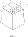
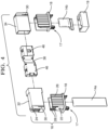
- a battery module 10, or battery pack assembly, is schematically illustrated in Figure 1 .
- the battery module 10 includes multiple battery cells 12 with positive and negative electrical terminals 14a, 14b (generally referred to as "terminal 14").
- the terminals 14 of the various cells 12 are electrically and mechanically connected to one another with bus bar assemblies 16 in a configuration that provides sufficient power for large electrical loads, such as automotive hybrid propulsion systems.
- the terminal 14 is provided by male terminal provided by a quadrangular copper plate. It should be understood that the terminal 14 may be configured differently, for example, as a female terminal. There is a potential shock hazard when the terminal 14 is left exposed. To mitigate the shock hazard when connecting and disconnecting the bus bar assembly 16 from the cells 12, a nonconductive terminal cap 18 is secured to a battery housing 19 by a connection 17 ( Fig. 4 ), for example, snaps. The terminal cap 18 may also be integrally formed with the battery housing 19, for example, during a plastic molding process.
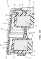
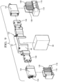
- the bus bar assembly 16 includes a bus bar 36 ( Figs. 2B , 2C and 4 ) substantially enclosed by a nonconductive shroud 20.
- the bus bar 36 has an end 46 provided by a female terminal that mechanically and electrically engages and mates with the male terminal 14 in an assembled condition.
- the nonconductive terminal cap 18 at least partially surrounds the terminal 14.
- a U-shaped perimeter wall 26 circumscribes at least a portion of the terminal 14, for example, on three sides, to provide a gap 44 configured to expose the terminal 14 in order to receive the end 46.
- the terminal cap 18 also has a post 38 that receives the terminal 14 and is arranged interiorly of the perimeter wall 26.
- the terminal 14 has a perimeter edge 40 bounding opposing faces 42 of the terminal 14.
- the post 38 extends outward from a base of the terminal cap 18 and provides an E-shaped configuration with the perimeter wall 26.
- the post 38 surrounds the perimeter edge 40 but leaves at least one of the faces 42 exposed. In this manner, the post 38 shields at least the end of the terminal 14 from contact.
- the perimeter wall 26 extends beyond the terminal 14 and beyond the post 38 to further isolate the terminal 14.
- the perimeter wall 26 and the post 38 cooperate to provide the gap 44 as "finger-proof," that is, preventing undesired contact with the terminal by a technician.
- finger-proof means a configuration that meets the standard set forth in IEC 60529 entitled “Degrees of Protection Provided by Enclosures” and code IP2XB relating to finger Ingress Protection.
- the "test finger” is based upon a solid object 12.5 mm in diameter or more and up to 80 mm long being prevented from entering an enclosure. Furthermore, if a standard test finger 80 mm long and 12 mm in diameter enters the enclosure there will be adequate clearance from live parts, i.e., the terminal. In this manner, the disclosed finger-proof terminal cap 18 prevents a technician from inadvertently touching the terminal 14 with the terminal cap 18 in place, for example, during assembly and/or removal of the bus bar assembly 16 with respect to the cells 12.
- the terminal cap 18 includes a first notch 28, and the shroud 20 includes a second notch 30.
- the shroud 20 is retained to the terminal cap 18 in the assembled condition by a retention feature.
- a first attachment feature 22 on the terminal cap 18, such as a protrusion cooperates with a finger-like second attachment feature 24 on the shroud 20, as best shown in Figure 2B .
- the first and second notches 28, 30 become nested with one another to enclose the terminal 14 and the end 46 and the finger begins to deflect outward as the finger slides over the protrusion.
- the second attachment feature 24 removably engages and interlocks with the first attachment feature 22. Engagement of the first and second attachment features 22, 24 signifies that the desired mechanical and electrical engagement between the terminal 14 and the end 46 has been achieved, that is, the female terminal end 46 has engaged the opposing faces 42 of the male terminal 14 and are safely enclosed. Once coupled, the retention feature prevents inadvertent decoupling of the bus bar 36 from the terminal 14 until the fingers and depressed and the bus bar assembly 16 is pulled away from the terminal cap 18.
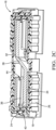
- the shroud 20 includes multiple shroud portions cooperating with one another to enclose the bus bar 36, which enables the bus bar to be serviced and the shroud to be reused.
- the multiple shroud portions include first and second shroud portions 32, 34 nested relative to one another in an overlapping relationship.
- the first shroud portion 32 includes a sleeve providing an opening at one end that receives an end of the second shroud portion 34.
- retentions features may be used between the first and second shroud portions 32, 34, a retention feature is not necessarily needed as the shroud portions are held together by the first and second notches 28, 30 when the bus bar assembly 16 is in the assembled condition with respect to the terminal caps 18.
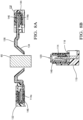
- FIGS 5A-5B illustrate one example variation of the terminal cap 18' configuration.
- the configuration used in the battery module 10 may depend upon the particular connection 17' and housing 19' arrangement as well as the given terminal 14a'.
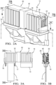
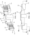
- FIG. 6A-9 Another example bus bar assembly 116 is shown in Figures 6A-9 . Like numerals indicate like elements. Figures 6A, 6B and 9 illustrate one example variation of the terminal cap 18 configuration secured using different housings 19, 19'. Similar to the first bus bar assembly 16, the nonconductive terminal cap 118 at least partially surrounds the terminal 114. There is a U-shaped perimeter wall 126 circumscribing at least a portion of the terminal 114 on three sides to provide the gap 144 exposing the terminal 114 to receive the end 146.
- the post 138 receives the terminal 114 interiorly of the perimeter wall 126.
- the post 138 shields the terminal 114 from contact in a manner similar to that described above in relation to the first bus bar assembly 16.
- the perimeter wall 26 and the post 38 cooperate to provide the gap 44 as "finger-proof,” that is, preventing undesired contact with the terminal by a technician.
- the second bus bar assembly 116 is received interiorly of the perimeter wall 126 instead of in overlapping relationship.
- the shroud 120 is retained to the terminal cap 118 in the assembled condition by a retention feature.
- the first attachment feature on the terminal cap is not illustrated in the Figures, but is provided by a protrusion cooperates with a finger-like second attachment feature 124 on the shroud 20, as best shown in Figures 6A and 9 . As the shroud 20 and end 46 are pushed into the gap 144 during assembly, the end 146 and the finger begins to deflect outward as the finger slides over the protrusion.
- the second attachment feature 124 removably engages and interlocks with the first attachment feature. Engagement of the first and second attachment features signifies that the desired mechanical and electrical engagement between the terminal 114 and the end 146 has been achieved, that is, the female terminal end 46 has engaged the opposing faces 142 of the male terminal 114 and are safely enclosed. Once coupled, the retention feature prevents inadvertent decoupling of the bus bar 136 from the terminal 114 until the fingers and depressed and the bus bar assembly 116 is pulled away from the terminal cap 118.
- the shroud 120 includes multiple shroud portions cooperating with one another to enclose the bus bar 136, which enables the bus bar to be serviced and the shroud to be reused.
- the multiple shroud portions include first and second shroud portions 132, 134 nested relative to one another in an overlapping relationship.
- the second shroud portion 134 is provided on each of opposing sides of the central first shroud portion 132.
- the first shroud portion 132 is provided by cover 50 snap-fit to a base 48.
- the first shroud portion 132 includes a sleeve providing an opening at one end that receives a respective end of the second shroud portion 134 using a snap-fit 52 when in the assembled condition. Snap-fits, which include a mating window 54 and a protrusion 56, are used to connect the various shroud pieces.
- the bus bar 136 includes a U-shaped portion 58 received in the first shroud portion 132 to provide a space between opposing ends 46 of the bus bar 136.
- the space accommodates an obstruction 60 arranged between the terminals 14 to enable compact packaging of the battery module 10 with respect to other components.
- a nonconductive terminal cap 18 is provided over a conductive battery cell terminal 14.
- the terminal caps 18 may be provided as loose pieces that are secured to the battery housing 19, if desired, or they may be integrated into the housing.
- the terminal cap 18 at least partially surrounds the terminal 14, which is a male terminal.
- the terminal cap 18 has a perimeter wall 26 configured to circumscribe at least a portion of the terminal 14.
- the terminal 14 is arranged in a post 38 that shields the terminal 14.
- the perimeter wall 26 and the post 38 cooperate to provide a finger-proof gap 44 that exposes the terminal 14.
- a bus bar assembly 16 is provided with a bus bar 36 having an end 46, which is a female terminal.
- a nonconductive shroud 20 encloses the bus bar 36 with the end 46 exposed through the shroud 20.
- the end 46 of the bus bar assembly 16 is pushed into the gap 44 and into engagement with the terminal 14 so that the shroud 20 mates to the terminal cap 18 to enclose the end 46.
- a first attachment feature 22 on the terminal cap 18 interlocks with a second attachment feature 24 on the shroud 20.
- the terminal cap can be secured battery cell about the terminal, rendering the terminal finger-safe.
- the battery module is finger-proof even with the bus bar assemblies disconnected, which allows for safe assembly and handling of the battery module during assembly and servicing of the battery module.
Landscapes
- Chemical & Material Sciences (AREA)
- Chemical Kinetics & Catalysis (AREA)
- Electrochemistry (AREA)
- General Chemical & Material Sciences (AREA)
- Engineering & Computer Science (AREA)
- Manufacturing & Machinery (AREA)
- Microelectronics & Electronic Packaging (AREA)
- Connection Of Batteries Or Terminals (AREA)
- Connections By Means Of Piercing Elements, Nuts, Or Screws (AREA)
- Multi-Conductor Connections (AREA)
Claims (8)
- Batteriemodul (10), umfassend:eine Batteriezelle (12), die eine elektrisch leitfähige erste Steckerklemme (14) aufweist; undeine zweite Batteriezelle (12), die eine elektrisch leitfähige zweite Steckerklemme (14) aufweist; undeine Sammelschienenbaugruppe (16), umfassend:eine jeweilige nichtleitende Klemmenkappe (18), die dazu ausgelegt ist, jede der Klemmen (14) mindestens teilweise zu umgeben, wobei die Klemmenkappen (18) jeweils eine Umfangswand (26) aufweisen, die dazu ausgelegt ist, mindestens einen Abschnitt der jeweiligen Klemme (14) zu umschreiben, um einen Spalt (44) bereitzustellen, der die Klemme (14) freilegt, wobei die Klemmenkappen (18) jeweils ein erstes Anbringungsmerkmal (22) beinhalten;eine Sammelschiene (36), die ein erstes Ende (46), das eine Buchsenklemme definiert, die mechanisch und elektrisch mit der ersten Steckerklemme (14) in Eingriff steht, und ein zweites Ende aufweist, das eine Buchsenklemme definiert, die in einem zusammengebauten Zustand mit der zweiten Steckerklemme (14) in Eingriff steht; undeine nichtleitende Ummantelung (20), die die Sammelschiene (36) umschließt und ein zweites Anbringungsmerkmal (24) beinhaltet, das in dem zusammengebauten Zustand lösbar mit dem ersten Anbringungsmerkmal (22) in Eingriff steht, um die Ummantelung (20) an den Klemmenkappen (18) zu befestigen, dadurch gekennzeichnet, dass die Klemmenkappen (18) jeweils einen Stift (38) aufweisen, der die jeweilige Klemme (14) aufnimmt und innen zu der jeweiligen Umfangswand (26) angeordnet ist, wobei der Spalt (44) zwischen jedem Stift (38) und der jeweiligen Umfangswand (26) bereitgestellt ist, wobei die Klemmen (14) jeweils eine Umfangskante (40) aufweisen, die gegenüberliegende Flächen (42) der jeweiligen Klemme (14) begrenzen, wobei die Stifte (38) jeweils die jeweilige Klemme (14) aufnehmen und die jeweilige Umfangskante (40) umgeben, aber mindestens eine der jeweiligen Flächen (42) freiliegend lassen, und wobei sich jede der Umfangswände (26) über die Stifte (38) hinaus erstreckt, wobei die Umfangswände (26) und die Stifte (38) zum Bereitstellen der Spalte (44) als Fingerschutz zusammenwirken und wobei die Ummantelung (20) einen ersten und zweiten Ummantelungsabschnitt (32, 34) beinhaltet, die in einer überlappenden Beziehung zueinander ineinander passen.
- Batteriemodul (10) nach Anspruch 1, wobei jede Umfangswand (26) eine U-Form aufweist, die an mindestens drei Seiten der jeweiligen Klemme (14) angeordnet ist, wobei sich die Umfangswand (26) über die jeweilige Klemme (14) hinaus erstreckt.
- Batteriemodul (10) nach Anspruch 1 oder 2, wobei jede Klemmenkappe (18) eine erste Kerbe (28) beinhaltet und die Ummantelung (20) eine jeweilige zweite Kerbe (30) beinhaltet, wobei die erste und die zweite Kerbe (28, 30) in dem zusammengebauten Zustand ineinander passen, um die Klemmen (14) und die Enden (46) der Sammelschiene (36) zu umschließen.
- Batteriemodul (10) nach einem der vorhergehenden Ansprüche, wobei eines des ersten und zweiten Anbringungsmerkmals (22, 24) ein Finger ist und das andere des ersten und zweiten Anbringungsmerkmals (22, 24) ein Vorsprung ist, wobei der Finger und der Vorsprung in dem zusammengebauten Zustand ineinandergreifen.
- Batteriemodul (10) nach einem der vorhergehenden Ansprüche, wobei der erste und der zweite Ummantelungsabschnitt (32, 34) in dem zusammengebauten Zustand in einer Schnappverbindung in Eingriff stehen, wobei der erste Ummantelungsabschnitt (32) ein erstes und ein zweites Gehäuse beinhaltet, die um einen Abschnitt der Sammelschiene (36) befestigt sind, und wobei das erste und das zweite Gehäuse in einer Öffnung in dem zweiten Ummantelungsabschnitt (34) aufgenommen sind.
- Batteriemodul (10) nach Anspruch 5, wobei die Sammelschiene (36) einen U-förmigen Abschnitt (58) beinhaltet, der in dem ersten Ummantelungsabschnitt (32) aufgenommen ist, um einen Raum zwischen gegenüberliegenden Enden der Sammelschiene (36) bereitzustellen, wobei der Raum dazu ausgelegt ist, ein Hindernis (60) aufzunehmen.
- Batteriemodul (10) nach einem der vorhergehenden Ansprüche, wobei jede Umfangswand (26) eine U-Form aufweist, die an mindestens drei Seiten der jeweiligen Klemme (14) angeordnet ist, wobei jede Klemmenkappe (18) einen Stift (38) aufweist, der innen zu der jeweiligen Umfangswand (26) angeordnet ist, wobei der Spalt (44) zwischen jedem Stift (38) und der jeweiligen Umfangswand (26) bereitgestellt ist, wobei jede Klemme (14) eine Steckerklemme mit einer Umfangskante (40) ist, die gegenüberliegende Flächen (42) der Klemme (14) begrenzt, wobei jeder Stift (38) die jeweilige Klemme (14) aufnimmt und die entsprechende Umfangskante (40) umgibt, aber mindestens eine der Flächen (42) freiliegend lässt, und das Ende (46) eine mit der Steckerklemme zusammenpassende Buchsenklemme ist, wobei sich jede Umfangswand (26) über den entsprechenden Stift (38) hinaus erstreckt und sich jeder Stift (38) über die jeweilige Klemme (14) hinaus erstreckt, wobei jede Umfangswand (26) und der jeweilige Stift (38) zum Bereitstellen des Spalts (44) als Fingerschutz zusammenwirken.
- Batteriemodul (10) nach Anspruch 7, wobei eines des ersten und zweiten Anbringungsmerkmals (22, 24) ein Finger ist und das andere des ersten und zweiten Anbringungsmerkmals (22, 24) ein Vorsprung ist, wobei der Finger und der Vorsprung in dem zusammengebauten Zustand ineinandergreifen.
Priority Applications (1)
| Application Number | Priority Date | Filing Date | Title |
|---|---|---|---|
| EP25174198.9A EP4571995A3 (de) | 2019-06-24 | 2020-06-23 | Messerklemen-sammelschiene mit fingerschutz |
Applications Claiming Priority (1)
| Application Number | Priority Date | Filing Date | Title |
|---|---|---|---|
| US201962865470P | 2019-06-24 | 2019-06-24 |
Related Child Applications (1)
| Application Number | Title | Priority Date | Filing Date |
|---|---|---|---|
| EP25174198.9A Division EP4571995A3 (de) | 2019-06-24 | 2020-06-23 | Messerklemen-sammelschiene mit fingerschutz |
Publications (2)
| Publication Number | Publication Date |
|---|---|
| EP3758100A1 EP3758100A1 (de) | 2020-12-30 |
| EP3758100B1 true EP3758100B1 (de) | 2025-06-04 |
Family
ID=71138544
Family Applications (3)
| Application Number | Title | Priority Date | Filing Date |
|---|---|---|---|
| EP25174198.9A Pending EP4571995A3 (de) | 2019-06-24 | 2020-06-23 | Messerklemen-sammelschiene mit fingerschutz |
| EP20181662.6A Pending EP3758099A1 (de) | 2019-06-24 | 2020-06-23 | Verschraubte sammelschiene mit fingerschutz |
| EP20181664.2A Active EP3758100B1 (de) | 2019-06-24 | 2020-06-23 | Messerklemmen-sammelschiene mit fingerschutz |
Family Applications Before (2)
| Application Number | Title | Priority Date | Filing Date |
|---|---|---|---|
| EP25174198.9A Pending EP4571995A3 (de) | 2019-06-24 | 2020-06-23 | Messerklemen-sammelschiene mit fingerschutz |
| EP20181662.6A Pending EP3758099A1 (de) | 2019-06-24 | 2020-06-23 | Verschraubte sammelschiene mit fingerschutz |
Country Status (3)
| Country | Link |
|---|---|
| US (4) | US11870165B2 (de) |
| EP (3) | EP4571995A3 (de) |
| CN (3) | CN119381708A (de) |
Families Citing this family (9)
| Publication number | Priority date | Publication date | Assignee | Title |
|---|---|---|---|---|
| CN113826285B (zh) * | 2019-05-24 | 2024-05-28 | 株式会社自动网络技术研究所 | 端子间连接结构 |
| US10910800B1 (en) * | 2019-10-22 | 2021-02-02 | Rivian Ip Holdings, Llc | Cover assembly for electrical busbar connection |
| DE102021100997B3 (de) * | 2021-01-19 | 2022-04-21 | Te Connectivity Germany Gmbh | Modulverbinder mit wenigstens einer verschieblichen Kontaktanordnung |
| EP4080686A1 (de) * | 2021-04-21 | 2022-10-26 | Rosenberger Hochfrequenztechnik GmbH & Co. KG | Elektrischer steckverbinder, elektrisches verbindungselement und elektrische steckverbindung |
| CN115732830A (zh) * | 2021-08-28 | 2023-03-03 | 莫列斯有限公司 | 电池连接模组及电池组 |
| US11749931B2 (en) * | 2021-12-21 | 2023-09-05 | GM Global Technology Operations LLC | Electrical connection unit for high-voltage battery packs |
| US12482892B2 (en) * | 2022-02-08 | 2025-11-25 | Ford Global Technologies, Llc | Thermal barrier for busbar of traction battery |
| EP4478519A4 (de) * | 2022-05-04 | 2025-05-21 | LG Energy Solution, Ltd. | Batteriesystem, energiespeichersystem damit und darin verwendete schutzabdeckung |
| US20230369724A1 (en) * | 2022-05-10 | 2023-11-16 | Rivian Ip Holdings, Llc | Battery pack apparatus |
Citations (3)
| Publication number | Priority date | Publication date | Assignee | Title |
|---|---|---|---|---|
| US5576516A (en) * | 1993-09-13 | 1996-11-19 | Yazaki Corporation | Cover of battery connecting terminal |
| US20140227913A1 (en) * | 2013-02-08 | 2014-08-14 | Lear Corporation | Electric Connector with a Lock to Retain a Terminal Within a Housing |
| EP3439116A1 (de) * | 2017-08-01 | 2019-02-06 | Aptiv Technologies Limited | Elektrischer hochstromsteckverbinder |
Family Cites Families (24)
| Publication number | Priority date | Publication date | Assignee | Title |
|---|---|---|---|---|
| US5804770A (en) * | 1995-09-19 | 1998-09-08 | Sumitomo Wiring Systems, Ltd. | Cover equipped electrical connection device and a cover for an electrical connection device |
| KR0151534B1 (ko) | 1995-10-30 | 1998-08-17 | 이종호 | 유기산 생성이 억제된 대장균 변이주 |
| US6276960B1 (en) | 2000-08-29 | 2001-08-21 | Delphi Technologies, Inc. | Electrical power connector system |
| EP1239506B1 (de) * | 2001-03-07 | 2012-04-25 | Yazaki Corporation | Schutzabdeckung und Sicherungsdose |
| ES2193849B1 (es) * | 2001-07-31 | 2005-03-01 | S.E. Acumulador Tudor, S.A. | Bateria de acumuladores electricos. |
| US7294020B2 (en) | 2005-05-25 | 2007-11-13 | Alcoa Fujikura Ltd. | Canted coil spring power terminal and sequence connection system |
| KR100821859B1 (ko) | 2006-02-09 | 2008-04-11 | 주식회사 엘지화학 | 전극단자 연결부의 안전성이 향상된 전지모듈 |
| EP2109904B1 (de) * | 2007-01-05 | 2012-09-19 | Johnson Controls Saft Advanced Power Solutions LLC | Batteriesystem |
| JP5375440B2 (ja) * | 2009-08-26 | 2013-12-25 | 住友電装株式会社 | 雄型コネクタ及びコネクタ装置 |
| KR101084213B1 (ko) | 2009-11-30 | 2011-11-17 | 삼성에스디아이 주식회사 | 전지 팩 |
| DE102010024519A1 (de) | 2010-06-21 | 2011-12-22 | Tyco Electronics Amp Gmbh | HV-Batteriebrücke |
| JP5803405B2 (ja) | 2011-08-10 | 2015-11-04 | 株式会社オートネットワーク技術研究所 | バスバーカバー、及びカバー付きバスバー |
| JP5934520B2 (ja) * | 2012-02-28 | 2016-06-15 | 矢崎総業株式会社 | バスバーモジュールのケースを覆う絶縁カバー |
| KR20140060633A (ko) | 2012-11-12 | 2014-05-21 | 주식회사 엘지화학 | 버스 바 어셈블리를 포함하는 전지모듈 및 이를 포함하는 전지팩 |
| KR20140094207A (ko) * | 2013-01-21 | 2014-07-30 | 삼성에스디아이 주식회사 | 전지 모듈 |
| KR102115040B1 (ko) | 2014-03-14 | 2020-05-26 | 엘에스이브이코리아 주식회사 | 고전압 수형 커넥터 |
| US9350127B2 (en) | 2014-03-24 | 2016-05-24 | Ford Global Technologies, Llc | Self-locating busbar assembly and alignment method |
| KR102283792B1 (ko) * | 2014-08-25 | 2021-08-02 | 삼성에스디아이 주식회사 | 이차 전지 모듈 |
| US10396405B2 (en) | 2014-11-10 | 2019-08-27 | Te Connectivity Corporation | Bus bar for a battery connector system |
| US9437860B2 (en) | 2014-11-20 | 2016-09-06 | Ford Global Technologies, Llc | Traction battery assembly having snap-in bus bar module |
| KR102396361B1 (ko) | 2015-08-18 | 2022-05-10 | 삼성에스디아이 주식회사 | 배터리 팩 |
| WO2017054187A1 (en) * | 2015-09-30 | 2017-04-06 | Byd Company Limited | Connector for power batteries, power battery module, power battery pack and vehicle |
| US10516144B2 (en) * | 2016-02-19 | 2019-12-24 | Gs Yuasa International Ltd. | Energy storage apparatus |
| US10003112B1 (en) | 2017-12-01 | 2018-06-19 | GM Global Technology Operations LLC | Battery backplane assembly with integrated bus bar connections and thermal management features |
-
2020
- 2020-05-02 US US16/865,315 patent/US11870165B2/en active Active
- 2020-05-02 US US16/865,316 patent/US11404804B2/en active Active
- 2020-06-23 EP EP25174198.9A patent/EP4571995A3/de active Pending
- 2020-06-23 EP EP20181662.6A patent/EP3758099A1/de active Pending
- 2020-06-23 EP EP20181664.2A patent/EP3758100B1/de active Active
- 2020-06-24 CN CN202411378215.7A patent/CN119381708A/zh active Pending
- 2020-06-24 CN CN202010586768.7A patent/CN112134040B/zh active Active
- 2020-06-24 CN CN202010585815.6A patent/CN112133875B/zh active Active
-
2022
- 2022-06-27 US US17/849,800 patent/US12355166B2/en active Active
-
2023
- 2023-07-26 US US18/226,397 patent/US12272889B2/en active Active
Patent Citations (3)
| Publication number | Priority date | Publication date | Assignee | Title |
|---|---|---|---|---|
| US5576516A (en) * | 1993-09-13 | 1996-11-19 | Yazaki Corporation | Cover of battery connecting terminal |
| US20140227913A1 (en) * | 2013-02-08 | 2014-08-14 | Lear Corporation | Electric Connector with a Lock to Retain a Terminal Within a Housing |
| EP3439116A1 (de) * | 2017-08-01 | 2019-02-06 | Aptiv Technologies Limited | Elektrischer hochstromsteckverbinder |
Also Published As
| Publication number | Publication date |
|---|---|
| CN119381708A (zh) | 2025-01-28 |
| CN112134040A (zh) | 2020-12-25 |
| EP4571995A2 (de) | 2025-06-18 |
| US11404804B2 (en) | 2022-08-02 |
| US11870165B2 (en) | 2024-01-09 |
| US12355166B2 (en) | 2025-07-08 |
| EP4571995A3 (de) | 2025-12-24 |
| US12272889B2 (en) | 2025-04-08 |
| EP3758100A1 (de) | 2020-12-30 |
| US20220328987A1 (en) | 2022-10-13 |
| CN112133875A (zh) | 2020-12-25 |
| EP3758099A1 (de) | 2020-12-30 |
| CN112134040B (zh) | 2025-07-04 |
| US20230369787A1 (en) | 2023-11-16 |
| US20200403329A1 (en) | 2020-12-24 |
| US20200403206A1 (en) | 2020-12-24 |
| CN112133875B (zh) | 2024-09-17 |
Similar Documents
| Publication | Publication Date | Title |
|---|---|---|
| EP3758100B1 (de) | Messerklemmen-sammelschiene mit fingerschutz | |
| CN109565129B (zh) | 电力连接器系统 | |
| EP2579395B1 (de) | Leistungsanschlusssystem | |
| CA2104464C (en) | Micropin connector system | |
| KR100624582B1 (ko) | 케이블 상호 접속 장치 | |
| CN107895872B (zh) | 汇流条头座组件 | |
| EP3595095B1 (de) | Industrielle steckdose | |
| JP2019527459A (ja) | 電力コネクタシステムのためのタブ端子を有するプラグコネクタ | |
| CN114223101B (zh) | 电连接器 | |
| US11975622B2 (en) | Charging inlet assembly having an AC charging module | |
| CA2732360A1 (en) | Surge snap-on module assembly | |
| US20070059973A1 (en) | Hot plug wire contact and connector assembly | |
| EP3488497B1 (de) | Kabelmontierbarer steckverbinder | |
| US20220071040A1 (en) | Socket connector for a power connector system | |
| KR101891780B1 (ko) | 원터치형 접지 구조를 갖는 커넥터 | |
| US20250219330A1 (en) | High voltage shielded electrical connector | |
| EP3787131B1 (de) | Sammelschienenadapter mit geschirmten anschlüssen |
Legal Events
| Date | Code | Title | Description |
|---|---|---|---|
| PUAI | Public reference made under article 153(3) epc to a published international application that has entered the european phase |
Free format text: ORIGINAL CODE: 0009012 |
|
| STAA | Information on the status of an ep patent application or granted ep patent |
Free format text: STATUS: THE APPLICATION HAS BEEN PUBLISHED |
|
| AK | Designated contracting states |
Kind code of ref document: A1 Designated state(s): AL AT BE BG CH CY CZ DE DK EE ES FI FR GB GR HR HU IE IS IT LI LT LU LV MC MK MT NL NO PL PT RO RS SE SI SK SM TR |
|
| AX | Request for extension of the european patent |
Extension state: BA ME |
|
| STAA | Information on the status of an ep patent application or granted ep patent |
Free format text: STATUS: REQUEST FOR EXAMINATION WAS MADE |
|
| 17P | Request for examination filed |
Effective date: 20210414 |
|
| RBV | Designated contracting states (corrected) |
Designated state(s): AL AT BE BG CH CY CZ DE DK EE ES FI FR GB GR HR HU IE IS IT LI LT LU LV MC MK MT NL NO PL PT RO RS SE SI SK SM TR |
|
| STAA | Information on the status of an ep patent application or granted ep patent |
Free format text: STATUS: EXAMINATION IS IN PROGRESS |
|
| 17Q | First examination report despatched |
Effective date: 20220310 |
|
| RAP3 | Party data changed (applicant data changed or rights of an application transferred) |
Owner name: APTIV TECHNOLOGIES LIMITED |
|
| RAP1 | Party data changed (applicant data changed or rights of an application transferred) |
Owner name: APTIV TECHNOLOGIES AG |
|
| RAP3 | Party data changed (applicant data changed or rights of an application transferred) |
Owner name: APTIV TECHNOLOGIES AG |
|
| REG | Reference to a national code |
Free format text: PREVIOUS MAIN CLASS: H01M0002200000 Ipc: H01R0013110000 Ref country code: DE Ref legal event code: R079 Ref document number: 602020052190 Country of ref document: DE Free format text: PREVIOUS MAIN CLASS: H01M0002200000 Ipc: H01R0013110000 |
|
| GRAP | Despatch of communication of intention to grant a patent |
Free format text: ORIGINAL CODE: EPIDOSNIGR1 |
|
| STAA | Information on the status of an ep patent application or granted ep patent |
Free format text: STATUS: GRANT OF PATENT IS INTENDED |
|
| RIC1 | Information provided on ipc code assigned before grant |
Ipc: H01R 13/506 20060101ALN20250310BHEP Ipc: H01M 50/55 20210101ALI20250310BHEP Ipc: H01M 50/505 20210101ALI20250310BHEP Ipc: H01R 11/28 20060101ALI20250310BHEP Ipc: H01R 13/11 20060101AFI20250310BHEP |
|
| RIC1 | Information provided on ipc code assigned before grant |
Ipc: H01R 13/506 20060101ALN20250314BHEP Ipc: H01M 50/55 20210101ALI20250314BHEP Ipc: H01M 50/505 20210101ALI20250314BHEP Ipc: H01R 11/28 20060101ALI20250314BHEP Ipc: H01R 13/11 20060101AFI20250314BHEP |
|
| GRAS | Grant fee paid |
Free format text: ORIGINAL CODE: EPIDOSNIGR3 |
|
| INTG | Intention to grant announced |
Effective date: 20250401 |
|
| RIC1 | Information provided on ipc code assigned before grant |
Ipc: H01R 13/506 20060101ALN20250321BHEP Ipc: H01M 50/55 20210101ALI20250321BHEP Ipc: H01M 50/505 20210101ALI20250321BHEP Ipc: H01R 11/28 20060101ALI20250321BHEP Ipc: H01R 13/11 20060101AFI20250321BHEP |
|
| GRAA | (expected) grant |
Free format text: ORIGINAL CODE: 0009210 |
|
| STAA | Information on the status of an ep patent application or granted ep patent |
Free format text: STATUS: THE PATENT HAS BEEN GRANTED |
|
| AK | Designated contracting states |
Kind code of ref document: B1 Designated state(s): AL AT BE BG CH CY CZ DE DK EE ES FI FR GB GR HR HU IE IS IT LI LT LU LV MC MK MT NL NO PL PT RO RS SE SI SK SM TR |
|
| P01 | Opt-out of the competence of the unified patent court (upc) registered |
Free format text: CASE NUMBER: APP_20093/2025 Effective date: 20250428 |
|
| REG | Reference to a national code |
Ref country code: GB Ref legal event code: FG4D |
|
| REG | Reference to a national code |
Ref country code: CH Ref legal event code: EP |
|
| REG | Reference to a national code |
Ref country code: DE Ref legal event code: R096 Ref document number: 602020052190 Country of ref document: DE |
|
| REG | Reference to a national code |
Ref country code: IE Ref legal event code: FG4D |
|
| PGFP | Annual fee paid to national office [announced via postgrant information from national office to epo] |
Ref country code: DE Payment date: 20250529 Year of fee payment: 6 |
|
| PGFP | Annual fee paid to national office [announced via postgrant information from national office to epo] |
Ref country code: GB Payment date: 20250611 Year of fee payment: 6 |
|
| PGFP | Annual fee paid to national office [announced via postgrant information from national office to epo] |
Ref country code: FR Payment date: 20250611 Year of fee payment: 6 |
|
| REG | Reference to a national code |
Ref country code: NL Ref legal event code: MP Effective date: 20250604 |
|
| PG25 | Lapsed in a contracting state [announced via postgrant information from national office to epo] |
Ref country code: ES Free format text: LAPSE BECAUSE OF FAILURE TO SUBMIT A TRANSLATION OF THE DESCRIPTION OR TO PAY THE FEE WITHIN THE PRESCRIBED TIME-LIMIT Effective date: 20250604 Ref country code: FI Free format text: LAPSE BECAUSE OF FAILURE TO SUBMIT A TRANSLATION OF THE DESCRIPTION OR TO PAY THE FEE WITHIN THE PRESCRIBED TIME-LIMIT Effective date: 20250604 |
|
| REG | Reference to a national code |
Ref country code: LT Ref legal event code: MG9D |
|
| PG25 | Lapsed in a contracting state [announced via postgrant information from national office to epo] |
Ref country code: GR Free format text: LAPSE BECAUSE OF FAILURE TO SUBMIT A TRANSLATION OF THE DESCRIPTION OR TO PAY THE FEE WITHIN THE PRESCRIBED TIME-LIMIT Effective date: 20250905 Ref country code: NO Free format text: LAPSE BECAUSE OF FAILURE TO SUBMIT A TRANSLATION OF THE DESCRIPTION OR TO PAY THE FEE WITHIN THE PRESCRIBED TIME-LIMIT Effective date: 20250904 |
|
| PG25 | Lapsed in a contracting state [announced via postgrant information from national office to epo] |
Ref country code: PL Free format text: LAPSE BECAUSE OF FAILURE TO SUBMIT A TRANSLATION OF THE DESCRIPTION OR TO PAY THE FEE WITHIN THE PRESCRIBED TIME-LIMIT Effective date: 20250604 |
|
| PG25 | Lapsed in a contracting state [announced via postgrant information from national office to epo] |
Ref country code: BG Free format text: LAPSE BECAUSE OF FAILURE TO SUBMIT A TRANSLATION OF THE DESCRIPTION OR TO PAY THE FEE WITHIN THE PRESCRIBED TIME-LIMIT Effective date: 20250604 |
|
| PG25 | Lapsed in a contracting state [announced via postgrant information from national office to epo] |
Ref country code: HR Free format text: LAPSE BECAUSE OF FAILURE TO SUBMIT A TRANSLATION OF THE DESCRIPTION OR TO PAY THE FEE WITHIN THE PRESCRIBED TIME-LIMIT Effective date: 20250604 |
|
| PG25 | Lapsed in a contracting state [announced via postgrant information from national office to epo] |
Ref country code: RS Free format text: LAPSE BECAUSE OF FAILURE TO SUBMIT A TRANSLATION OF THE DESCRIPTION OR TO PAY THE FEE WITHIN THE PRESCRIBED TIME-LIMIT Effective date: 20250904 |
|
| PG25 | Lapsed in a contracting state [announced via postgrant information from national office to epo] |
Ref country code: LV Free format text: LAPSE BECAUSE OF FAILURE TO SUBMIT A TRANSLATION OF THE DESCRIPTION OR TO PAY THE FEE WITHIN THE PRESCRIBED TIME-LIMIT Effective date: 20250604 |
|
| PG25 | Lapsed in a contracting state [announced via postgrant information from national office to epo] |
Ref country code: NL Free format text: LAPSE BECAUSE OF FAILURE TO SUBMIT A TRANSLATION OF THE DESCRIPTION OR TO PAY THE FEE WITHIN THE PRESCRIBED TIME-LIMIT Effective date: 20250604 |
|
| PG25 | Lapsed in a contracting state [announced via postgrant information from national office to epo] |
Ref country code: PT Free format text: LAPSE BECAUSE OF FAILURE TO SUBMIT A TRANSLATION OF THE DESCRIPTION OR TO PAY THE FEE WITHIN THE PRESCRIBED TIME-LIMIT Effective date: 20251006 |
|
| REG | Reference to a national code |
Ref country code: AT Ref legal event code: MK05 Ref document number: 1801313 Country of ref document: AT Kind code of ref document: T Effective date: 20250604 |
|
| PG25 | Lapsed in a contracting state [announced via postgrant information from national office to epo] |
Ref country code: IS Free format text: LAPSE BECAUSE OF FAILURE TO SUBMIT A TRANSLATION OF THE DESCRIPTION OR TO PAY THE FEE WITHIN THE PRESCRIBED TIME-LIMIT Effective date: 20251004 |
|
| PG25 | Lapsed in a contracting state [announced via postgrant information from national office to epo] |
Ref country code: SM Free format text: LAPSE BECAUSE OF FAILURE TO SUBMIT A TRANSLATION OF THE DESCRIPTION OR TO PAY THE FEE WITHIN THE PRESCRIBED TIME-LIMIT Effective date: 20250604 Ref country code: AT Free format text: LAPSE BECAUSE OF FAILURE TO SUBMIT A TRANSLATION OF THE DESCRIPTION OR TO PAY THE FEE WITHIN THE PRESCRIBED TIME-LIMIT Effective date: 20250604 |
|
| PG25 | Lapsed in a contracting state [announced via postgrant information from national office to epo] |
Ref country code: CZ Free format text: LAPSE BECAUSE OF FAILURE TO SUBMIT A TRANSLATION OF THE DESCRIPTION OR TO PAY THE FEE WITHIN THE PRESCRIBED TIME-LIMIT Effective date: 20250604 |
|
| PG25 | Lapsed in a contracting state [announced via postgrant information from national office to epo] |
Ref country code: EE Free format text: LAPSE BECAUSE OF FAILURE TO SUBMIT A TRANSLATION OF THE DESCRIPTION OR TO PAY THE FEE WITHIN THE PRESCRIBED TIME-LIMIT Effective date: 20250604 |
|
| PG25 | Lapsed in a contracting state [announced via postgrant information from national office to epo] |
Ref country code: RO Free format text: LAPSE BECAUSE OF FAILURE TO SUBMIT A TRANSLATION OF THE DESCRIPTION OR TO PAY THE FEE WITHIN THE PRESCRIBED TIME-LIMIT Effective date: 20250604 Ref country code: SK Free format text: LAPSE BECAUSE OF FAILURE TO SUBMIT A TRANSLATION OF THE DESCRIPTION OR TO PAY THE FEE WITHIN THE PRESCRIBED TIME-LIMIT Effective date: 20250604 |
|
| REG | Reference to a national code |
Ref country code: CH Ref legal event code: H13 Free format text: ST27 STATUS EVENT CODE: U-0-0-H10-H13 (AS PROVIDED BY THE NATIONAL OFFICE) Effective date: 20260127 |
|
| PG25 | Lapsed in a contracting state [announced via postgrant information from national office to epo] |
Ref country code: IT Free format text: LAPSE BECAUSE OF FAILURE TO SUBMIT A TRANSLATION OF THE DESCRIPTION OR TO PAY THE FEE WITHIN THE PRESCRIBED TIME-LIMIT Effective date: 20250604 |