EP4570451A1 - Wagenwechselsteuerungsverfahren und wagenwechselsystem - Google Patents
Wagenwechselsteuerungsverfahren und wagenwechselsystem Download PDFInfo
- Publication number
- EP4570451A1 EP4570451A1 EP23892789.1A EP23892789A EP4570451A1 EP 4570451 A1 EP4570451 A1 EP 4570451A1 EP 23892789 A EP23892789 A EP 23892789A EP 4570451 A1 EP4570451 A1 EP 4570451A1
- Authority
- EP
- European Patent Office
- Prior art keywords
- jacking
- cart
- tested
- assembly
- transmission member
- Prior art date
- Legal status (The legal status is an assumption and is not a legal conclusion. Google has not performed a legal analysis and makes no representation as to the accuracy of the status listed.)
- Pending
Links
Images


Classifications
-
- G—PHYSICS
- G05—CONTROLLING; REGULATING
- G05B—CONTROL OR REGULATING SYSTEMS IN GENERAL; FUNCTIONAL ELEMENTS OF SUCH SYSTEMS; MONITORING OR TESTING ARRANGEMENTS FOR SUCH SYSTEMS OR ELEMENTS
- G05B19/00—Program-control systems
- G05B19/02—Program-control systems electric
- G05B19/18—Numerical control [NC], i.e. automatically operating machines, in particular machine tools, e.g. in a manufacturing environment, so as to execute positioning, movement or co-ordinated operations by means of program data in numerical form
- G05B19/402—Numerical control [NC], i.e. automatically operating machines, in particular machine tools, e.g. in a manufacturing environment, so as to execute positioning, movement or co-ordinated operations by means of program data in numerical form characterised by control arrangements for positioning, e.g. centring a tool relative to a hole in the workpiece, additional detection means to correct position
-
- B—PERFORMING OPERATIONS; TRANSPORTING
- B23—MACHINE TOOLS; METAL-WORKING NOT OTHERWISE PROVIDED FOR
- B23P—METAL-WORKING NOT OTHERWISE PROVIDED FOR; COMBINED OPERATIONS; UNIVERSAL MACHINE TOOLS
- B23P19/00—Machines for simply fitting together or separating metal parts or objects, or metal and non-metal parts, whether or not involving some deformation; Tools or devices therefor so far as not provided for in other classes
-
- B—PERFORMING OPERATIONS; TRANSPORTING
- B25—HAND TOOLS; PORTABLE POWER-DRIVEN TOOLS; MANIPULATORS
- B25J—MANIPULATORS; CHAMBERS PROVIDED WITH MANIPULATION DEVICES
- B25J9/00—Program-controlled manipulators
- B25J9/16—Program controls
- B25J9/1679—Program controls characterised by the tasks executed
-
- B—PERFORMING OPERATIONS; TRANSPORTING
- B25—HAND TOOLS; PORTABLE POWER-DRIVEN TOOLS; MANIPULATORS
- B25J—MANIPULATORS; CHAMBERS PROVIDED WITH MANIPULATION DEVICES
- B25J9/00—Program-controlled manipulators
- B25J9/16—Program controls
- B25J9/1679—Program controls characterised by the tasks executed
- B25J9/1687—Assembly, peg and hole, palletising, straight line, weaving pattern movement
-
- G—PHYSICS
- G05—CONTROLLING; REGULATING
- G05B—CONTROL OR REGULATING SYSTEMS IN GENERAL; FUNCTIONAL ELEMENTS OF SUCH SYSTEMS; MONITORING OR TESTING ARRANGEMENTS FOR SUCH SYSTEMS OR ELEMENTS
- G05B19/00—Program-control systems
- G05B19/02—Program-control systems electric
- G05B19/418—Total factory control, i.e. centrally controlling a plurality of machines, e.g. direct or distributed numerical control [DNC], flexible manufacturing systems [FMS], integrated manufacturing systems [IMS] or computer integrated manufacturing [CIM]
- G05B19/41815—Total factory control, i.e. centrally controlling a plurality of machines, e.g. direct or distributed numerical control [DNC], flexible manufacturing systems [FMS], integrated manufacturing systems [IMS] or computer integrated manufacturing [CIM] characterised by the cooperation between machine tools, manipulators and conveyor or other workpiece supply system, workcell
-
- G—PHYSICS
- G05—CONTROLLING; REGULATING
- G05B—CONTROL OR REGULATING SYSTEMS IN GENERAL; FUNCTIONAL ELEMENTS OF SUCH SYSTEMS; MONITORING OR TESTING ARRANGEMENTS FOR SUCH SYSTEMS OR ELEMENTS
- G05B19/00—Program-control systems
- G05B19/02—Program-control systems electric
- G05B19/418—Total factory control, i.e. centrally controlling a plurality of machines, e.g. direct or distributed numerical control [DNC], flexible manufacturing systems [FMS], integrated manufacturing systems [IMS] or computer integrated manufacturing [CIM]
- G05B19/41845—Total factory control, i.e. centrally controlling a plurality of machines, e.g. direct or distributed numerical control [DNC], flexible manufacturing systems [FMS], integrated manufacturing systems [IMS] or computer integrated manufacturing [CIM] characterised by system universality, reconfigurability, modularity
-
- G—PHYSICS
- G05—CONTROLLING; REGULATING
- G05B—CONTROL OR REGULATING SYSTEMS IN GENERAL; FUNCTIONAL ELEMENTS OF SUCH SYSTEMS; MONITORING OR TESTING ARRANGEMENTS FOR SUCH SYSTEMS OR ELEMENTS
- G05B19/00—Program-control systems
- G05B19/02—Program-control systems electric
- G05B19/418—Total factory control, i.e. centrally controlling a plurality of machines, e.g. direct or distributed numerical control [DNC], flexible manufacturing systems [FMS], integrated manufacturing systems [IMS] or computer integrated manufacturing [CIM]
- G05B19/41805—Total factory control, i.e. centrally controlling a plurality of machines, e.g. direct or distributed numerical control [DNC], flexible manufacturing systems [FMS], integrated manufacturing systems [IMS] or computer integrated manufacturing [CIM] characterised by assembly
-
- G—PHYSICS
- G05—CONTROLLING; REGULATING
- G05B—CONTROL OR REGULATING SYSTEMS IN GENERAL; FUNCTIONAL ELEMENTS OF SUCH SYSTEMS; MONITORING OR TESTING ARRANGEMENTS FOR SUCH SYSTEMS OR ELEMENTS
- G05B2219/00—Program-control systems
- G05B2219/30—Nc systems
- G05B2219/31—From computer integrated manufacturing till monitoring
- G05B2219/31031—Assembly, manipulator cell
-
- G—PHYSICS
- G05—CONTROLLING; REGULATING
- G05B—CONTROL OR REGULATING SYSTEMS IN GENERAL; FUNCTIONAL ELEMENTS OF SUCH SYSTEMS; MONITORING OR TESTING ARRANGEMENTS FOR SUCH SYSTEMS OR ELEMENTS
- G05B2219/00—Program-control systems
- G05B2219/30—Nc systems
- G05B2219/31—From computer integrated manufacturing till monitoring
- G05B2219/31058—Determination of assembly tooling, fixture
-
- G—PHYSICS
- G05—CONTROLLING; REGULATING
- G05B—CONTROL OR REGULATING SYSTEMS IN GENERAL; FUNCTIONAL ELEMENTS OF SUCH SYSTEMS; MONITORING OR TESTING ARRANGEMENTS FOR SUCH SYSTEMS OR ELEMENTS
- G05B2219/00—Program-control systems
- G05B2219/30—Nc systems
- G05B2219/31—From computer integrated manufacturing till monitoring
- G05B2219/31372—Mes manufacturing execution system
-
- G—PHYSICS
- G05—CONTROLLING; REGULATING
- G05B—CONTROL OR REGULATING SYSTEMS IN GENERAL; FUNCTIONAL ELEMENTS OF SUCH SYSTEMS; MONITORING OR TESTING ARRANGEMENTS FOR SUCH SYSTEMS OR ELEMENTS
- G05B2219/00—Program-control systems
- G05B2219/30—Nc systems
- G05B2219/37—Measurements
- G05B2219/37221—Probe fixture to know datum points
-
- G—PHYSICS
- G05—CONTROLLING; REGULATING
- G05B—CONTROL OR REGULATING SYSTEMS IN GENERAL; FUNCTIONAL ELEMENTS OF SUCH SYSTEMS; MONITORING OR TESTING ARRANGEMENTS FOR SUCH SYSTEMS OR ELEMENTS
- G05B2219/00—Program-control systems
- G05B2219/30—Nc systems
- G05B2219/50—Machine tool, machine tool null till machine tool work handling
- G05B2219/50125—Configurable fixture, jig
-
- G—PHYSICS
- G05—CONTROLLING; REGULATING
- G05B—CONTROL OR REGULATING SYSTEMS IN GENERAL; FUNCTIONAL ELEMENTS OF SUCH SYSTEMS; MONITORING OR TESTING ARRANGEMENTS FOR SUCH SYSTEMS OR ELEMENTS
- G05B2219/00—Program-control systems
- G05B2219/30—Nc systems
- G05B2219/50—Machine tool, machine tool null till machine tool work handling
- G05B2219/50127—Modular fixture, use of clamps and locators, the latter also for positioning
-
- Y—GENERAL TAGGING OF NEW TECHNOLOGICAL DEVELOPMENTS; GENERAL TAGGING OF CROSS-SECTIONAL TECHNOLOGIES SPANNING OVER SEVERAL SECTIONS OF THE IPC; TECHNICAL SUBJECTS COVERED BY FORMER USPC CROSS-REFERENCE ART COLLECTIONS [XRACs] AND DIGESTS
- Y02—TECHNOLOGIES OR APPLICATIONS FOR MITIGATION OR ADAPTATION AGAINST CLIMATE CHANGE
- Y02P—CLIMATE CHANGE MITIGATION TECHNOLOGIES IN THE PRODUCTION OR PROCESSING OF GOODS
- Y02P90/00—Enabling technologies with a potential contribution to greenhouse gas [GHG] emissions mitigation
- Y02P90/02—Total factory control, e.g. smart factories, flexible manufacturing systems [FMS] or integrated manufacturing systems [IMS]
Definitions
- the present disclosure relates to the field of automatic assembly technologies, and in particular to a cart remodeling control method and system.
- a battery production line mainly uses semi-automatic devices for implementing processes such as battery processing, assembling, conveying, and testing.
- transfer apparatuses are used in the battery production line to transfer battery components from the previous process to the next process for assembling.
- each transfer apparatus is only capable of adapting to battery components of one specification and size, and cannot automatically be compatible with products in different sizes.
- the transfer apparatus needs to be manually replaced, resulting in a low production efficiency.
- the present disclosure proposes a cart remodeling control method and system, which can reduce labor costs and production costs, and further help improve the production efficiency during product remodeling.
- embodiments of the present disclosure provide a cart remodeling control method, and the method includes:
- the current blueprint information of the cart to be tested is matched with the target blueprint information for consistency; if the current blueprint information is inconsistent with the target blueprint information, it is determined to perform remodeling automatically for the cart to be tested, specifically: first, control the jacking mechanism to perform positioning and jacking actions on the cart to be tested, and then send the control instruction to the robot to control the gripper mechanism arranged on the robot to perform the pick-and-place action on the at least one position-limiting block on the tray; and when the position of the at least one position-limiting block matches the position-limiting block position in the target blueprint information, determine that the remodeling of the cart to be tested is successful.
- the method before the cart to be tested reaches the preset position, the method further includes: receiving an entry request sent by an automated guided vehicle; sending, based on the entry request, an entry permit instruction to the automated guided vehicle; wherein the entry permit instruction is used for instructing the automated guided vehicle to pull the cart to be tested to move until the cart to be tested reaches the preset position.
- the cart to be tested when the automated guided vehicle pulls the cart to be tested to move, according to the entry request sent by the automated guided vehicle, the cart to be tested is capable of being moved to a remodeling station, so as to control the cart to be tested to perform automatic remodeling.
- the method before sending the control instruction to the robot, further includes: receiving a position-limiting block position fed back by the robot; sending the control instruction to the robot if the position-limiting block position fed back by the robot is consistent with the position-limiting block position in the target blueprint information; wherein the position-limiting block position indicates a hole site serial number corresponding to the position-limiting block to be picked and placed by the robot.
- the robot before the robot performs the pick-and-place action, the robot first feeds back to the controller a current hole site serial number to be picked, and then performs consistency calibration. Only when the two are consistent, the controller sends the control instruction to the robot, which can play a role in error-proofing and fool-proofing of the position-limiting block position, thereby preventing the robot from picking a position-limiting block with the wrong hole site serial number.
- sending the control instruction to the robot includes: sending a photographing instruction to the robot, wherein the photographing instruction is used for controlling a visual detection system arranged on the robot to take photographs of a site to be picked and a site to be placed, and performing offset compensation on positions of the site to be picked and the site to be placed; and sending a pick-and-place instruction to the robot, wherein the pick-and-place instruction is used for controlling the gripper mechanism to pick the position-limiting block on the tray from the site to be picked, and controlling the gripper mechanism to place the position-limiting block into the site to be placed in the tray, so that the position of at least one position-limiting block conforms to the corresponding position-limiting block position in the target blueprint information.
- the controller can control the visual detection system to perform visual guide for offset correction on the picking position, and is capable of accurately determining, according to the corresponding offset data, a target position that the gripper assembly in the gripper mechanism intends to reach, so that according to the determined target position, the controller can control the gripper assembly to move to the target position, and therefore, the gripper assembly can move to the accurate picking position to perform pick-and-place on the position-limiting block, thereby improving the efficiency of position-limiting block replacement or position adjustment.
- the method further includes: writing the target blueprint information to an electronic tag on the cart to be tested through a reader/writer; reading, through the reader/writer, newly written blueprint information of the electronic tag; and allowing the cart to be tested to be released if the newly written blueprint information is consistent with the target blueprint information.
- the newly written blueprint information in the electronic tag can be verified with the target blueprint information issued by an MES system, which is used for determining whether the target blueprint information is successfully written into the electronic tag of the cart to be tested, and can also play a role in the error-proof and fool-proof function.
- the method when the cart to be tested reaches the preset position, the method further includes: controlling a position-limiting assembly on the jacking mechanism to perform a position-limiting action so that the cart to be tested stays at the preset position; wherein the position-limiting assembly is used for limiting the position of the cart to be tested relative to the jacking mechanism.
- the position-limiting assembly performs the position-limiting action on the cart to be tested, thereby achieving rough positioning of the cart to be tested.
- the jacking mechanism also includes a positioning assembly and a jacking assembly; and controlling the jacking mechanism to perform the positioning and jacking actions on the cart to be tested includes: controlling the positioning assembly to perform the positioning action, and controlling the jacking assembly to perform the jacking action, so as to complete the positioning and jacking actions of the jacking mechanism on the cart to be tested.
- Controlling the jacking mechanism to perform the releasing action includes: controlling the positioning assembly and the jacking assembly to perform the releasing action, and controlling the position-limiting assembly to perform the releasing action.
- the positioning assembly and the jacking assembly perform the positioning and jacking actions on the cart to be tested, so that precise positioning of the cart to be tested can be achieved.
- the method before sending the control instruction to the robot, the method further includes: controlling a driving member to perform a first driving action to drive a transmission member to move to an initial position.
- the method also includes: controlling the driving member to perform a second driving action to drive the transmission member to move to a corresponding axial positioning position in the target blueprint information.
- the driving member before adjusting the position-limiting block, the driving member is first controlled to drive the transmission member to the initial position; after the adjustment of the position-limiting block is completed, the driving member is controlled to drive the transmission member to move to the corresponding axial positioning position in the target blueprint information. In this way, the difficulty in debugging can be reduced and the efficiency of on-site debugging can be improved.
- the driving member includes a first driving member arranged in a jacking sleeve assembly on the jacking mechanism
- the transmission member includes a transverse transmission member arranged in the tray.
- Controlling the driving member to perform the first driving action to drive the transmission member to move to the initial position includes: controlling the jacking sleeve assembly on the jacking mechanism to perform a nut recognition action so that the first driving member is connected to the transverse transmission member through a first connecting member in the jacking sleeve assembly, and controlling the first driving member to drive the first connecting member to rotate, so as to drive, through the first connecting member, the transverse transmission member to move to an initial position of the transverse transmission member; wherein the transverse transmission member extends in a first direction.
- the first connecting member and the first driving member are arranged in the jacking sleeve assembly, and therefore, the first connecting member can be driven to rotate by the first driving member, so as to drive the transverse transmission member in the tray that is sleeved with the first connecting member to rotate, so that the position of a structural member connected to the transverse transmission member in the tray can be adjusted.
- the first connecting member and the first driving member are both arranged on a first nut recognition assembly, and the first connecting member can be driven by the first nut recognition assembly to move in a direction close to the transverse transmission member in the tray, so that the first connecting member can be sleeved with the transverse transmission member. In this way, the position of the structural member in the tray that needs to be moved can be quickly adjusted by the jacking sleeve assembly.
- the driving member includes a second driving member arranged in a gripper sleeve assembly on the gripper mechanism
- the transmission member includes a longitudinal transmission member arranged in the tray.
- Controlling the driving member to perform the first driving action to drive the transmission member to move to the initial position further includes: starting a robot, and controlling the robot to move from a first position to a second position; controlling the gripper sleeve assembly on the gripper mechanism to perform a nut recognition action so that the second driving member is connected to the longitudinal transmission member through a second connecting member in the gripper sleeve assembly, and controlling the second driving member to drive the second connecting member to rotate, so as to drive, through the second connecting member, the longitudinal transmission member to move to an initial position of the longitudinal transmission member; wherein the longitudinal transmission member extends in a second direction.
- the second connecting member and the second driving member are arranged in the gripper sleeve assembly, and therefore, the second connecting member can be driven to rotate by the second driving member, so as to drive the longitudinal transmission member in the tray that is sleeved with the second connecting member to rotate, so that the position of a structural member connected to the longitudinal transmission member in the tray can be adjusted.
- the second connecting member is arranged on a second nut recognition assembly, and the second connecting member can be driven by the second nut recognition assembly to move in a direction close to the longitudinal transmission member in the tray, so that the second connecting member can be sleeved with the longitudinal transmission member. In this way, the position of the other structural member in the tray that needs to be moved can be quickly adjusted by the gripper sleeve assembly.
- controlling the driving member to perform the second driving action to drive the transmission member to move to the axial positioning position of the target blueprint information includes: controlling the second driving member to rotate to drive the longitudinal transmission member to reach the positioning position in the second direction in the target blueprint information, and controlling the gripper sleeve assembly on the gripper mechanism to perform a separation action, and controlling the robot to return to the first position; controlling the first driving member to rotate to drive the transverse transmission member to reach the positioning position in the first direction in the target blueprint information, and controlling the jacking sleeve assembly on the jacking mechanism to perform the separation action.
- the first nut recognition assembly drives the first connecting member to separate from the transverse transmission member; and after completing the driving process of the longitudinal transmission member, the second nut recognition assembly drives the second connecting member to separate from the longitudinal transmission member.
- the embodiments of the present disclosure provide a cart remodeling system, and the system includes:
- the gripper mechanism is arranged in the cart remodeling system, and the gripper assembly is arranged in the gripper mechanism, the position-limiting block can be picked or the position-limiting block can be placed through the gripper assembly.
- the gripper mechanism may be mounted on the robot, and the robot can drive the gripper mechanism to move to drive the movement of the position-limiting block, so that the position-limiting block on the cart to be tested can be replaced, or the position of the position-limiting block can be adjusted.
- the jacking mechanism including the position-limiting assembly is provided. The position of the cart to be tested relative to the jacking mechanism can be limited through the position-limiting assembly, thereby limiting the movement of the cart to be tested so that the cart to be tested can be parked at the preset position.
- the jacking mechanism further includes a jacking sleeve assembly; the jacking sleeve assembly includes a first driving member, a first connecting member, and a first nut recognition assembly; wherein the first nut recognition assembly is arranged on the jacking bracket; the first driving member is fixed on the first nut recognition assembly, and the first connecting member is drivingly connected to an output shaft of the first driving member.
- the first connecting member is capable of moving in the direction close to the transverse transmission member in the tray and being connected to the transverse transmission member; and driven by the first driving member, the first connecting member is capable of driving the transverse transmission member to rotate.
- the first connecting member is arranged in the jacking sleeve assembly and the first driving member drivingly connected to the first connecting member is further arranged; therefore, the first connecting member can be driven to rotate by the first driving member.
- the transverse transmission member in the tray that is sleeved with the first connecting member can be driven to rotate, so that the position of the structural member in the tray connected to the transverse transmission member can be adjusted.
- the first connecting member and the first driving member are both arranged on the first nut recognition assembly.
- the first nut recognition assembly can drive the first connecting member to move in the direction close to the transverse transmission member in the tray, so that the first connecting member can be sleeved to the transverse transmission member. After completing the driving process of the transverse transmission member, the first connecting member can also be driven by the first nut recognition assembly to separate from the transverse transmission member. In this way, the position of the structural member in the tray that needs to be moved can be quickly adjusted by the jacking sleeve assembly.
- the jacking mechanism further includes a jacking assembly.
- the jacking assembly includes a jacking driving member, a jacking transmission member, and a jacking beam.
- the jacking beam is slidably connected to the jacking bracket, for supporting the cart to be tested.
- One end of the jacking driving member is connected to the jacking bracket, and the other end is connected to the jacking transmission member.
- the jacking transmission member is slidably arranged on the jacking bracket, and drivingly connected to the jacking beam.
- the jacking assembly is provided with the jacking beam slidably connected to the jacking bracket, the jacking beam can carry and support the cart to be tested; and the jacking transmission member is slidably arranged on the jacking bracket.
- the jacking driving member is arranged between the jacking transmission member and the jacking bracket, and the jacking driving member can drive the jacking transmission member to move, thereby driving the jacking beam to move in the vertical direction.
- the cart to be tested when the cart to be tested is in the position corresponding to the jacking mechanism, the cart to be tested can be jacked by the jacking assembly in the jacking mechanism, so that the cart to be tested can move in the vertical direction, thereby allowing the cart to be tested to be separated from the ground, so that the cart to be tested is at the required height.
- the position-limiting assembly includes a position-limiting driving member and a position-limiting member.
- the position-limiting driving member is fixed on the jacking bracket, and the position-limiting member is connected to the output shaft of the position-limiting driving member.
- the position-limiting member is capable of being connected to the cart to be tested to limit the position of the cart to be tested relative to the jacking mechanism.
- the position-limiting driving member is arranged in the position-limiting assembly, and the position-limiting member may be driven by the position-limiting driving member to move. Before the cart to be tested moves into the jacking mechanism, the position-limiting member may be driven by the position-limiting driving member to move in a direction away from the center of the jacking mechanism, so as to facilitate the cart to be tested to enter the interior of the jacking mechanism.
- the position-limiting member may be driven by the position-limiting driving member to move in the direction close to the cart to be tested until the position-limiting member abuts against the cart to be tested, which can limit the movement of the cart to be tested relative to the jacking mechanism, thereby limiting the cart to be tested to the preset position.
- the gripper mechanism further includes a gripper sleeve assembly.
- the gripper sleeve assembly includes a second driving member, a second connecting member, and a second nut recognition assembly.
- the second nut recognition assembly and the second driving member are both arranged on the mechanical arm of the robot.
- the second connecting member is drivingly connected to the second nut recognition assembly, and the second connecting member is drivingly connected to the output shaft of the second driving member.
- the second connecting member is capable of moving in a direction close to the longitudinal transmission member in the tray and is connected to the longitudinal transmission member.
- the second driving member the second connecting member is capable of driving the longitudinal transmission member to rotate.
- the second connecting member is arranged in the gripper sleeve assembly and the second driving member drivingly connected to the second connecting member is further arranged; therefore, the second connecting member can be driven to rotate by the second driving member.
- the longitudinal transmission member in the tray that is sleeved with the second connecting member can be driven to rotate, so that the position of the structural member in the tray connected to the longitudinal transmission member can be adjusted.
- the second connecting member is arranged on the second nut recognition assembly. The second nut recognition assembly can drive the second connecting member to move in the direction close to the longitudinal transmission member in the tray, so that the second connecting member can be sleeved to the longitudinal transmission member.
- the second connecting member can also be driven by the second nut recognition assembly to separate from the longitudinal transmission member. In this way, the position of the other structural member in the tray that needs to be moved can be quickly adjusted by the gripper sleeve assembly.
- the gripper mechanism further includes a visual detection system, and the visual detection system is capable of being electrically coupled to a controller.
- the visual detection system is used for taking photographs of the site to be picked and the site to be placed, and performing offset compensation on positions of the site to be picked and the site to be placed.
- the visual detection system is arranged on the gripper mechanism, information about the target position that the gripper assembly in the gripper mechanism intends to reach can be determined through the visual detection system, so that the gripper assembly can be controlled, according to the determined target position, to move to the target position, thereby enabling the gripper assembly to move to an accurate picking position or placing position, for improving the efficiency of replacing or positioning adjustment of the position-limiting block on the tray.
- the cart remodeling control method and system provided in the embodiments of the present disclosure, when the cart to be tested reaches the preset position, the current blueprint information of the cart to be tested is acquired, and the current blueprint information is matched with the target blueprint information sent by the manufacturing execution system for consistency; if the current blueprint information is inconsistent with the target blueprint information, it is determined to perform remodeling automatically for the cart to be tested, specifically: first, control the jacking mechanism to perform positioning and jacking actions on the cart to be tested, and then send the control instruction to the robot to control the gripper mechanism arranged on the robot to perform the pick-and-place action on the at least one position-limiting block on the tray; and when the position of the at least one position-limiting block matches the position-limiting block position in the target blueprint information, determine that the remodeling of the cart to be tested is successful, and release the cart.
- the blueprint information may be automatically issued by the manufacturing execution system and recognized through the electronic tag, which improves the data security; on the other hand, remodeling performed on the cart has been changed from manual replacement to automatic replacement, and the robot is simple in a remodeling logic, there is no need to configure a plurality of sensors, and it further improves the degree of automation of the devices, while reducing the labor costs and production costs, thereby improving the production efficiency during product remodeling.
- controlling the lead screw displacement in the tray and performing the pick-and-place action on the at least one position-limiting block on the tray can also adapt to components to be transferred with different specifications and parameters, thereby improving the compatibility.
- first ⁇ second ⁇ third involved in the embodiments of the present disclosure is only used to distinguish similar objects, does not represent a particular order for the objects, and it is understood that “first ⁇ second ⁇ third” may be interchanged, where permitted, in a particular order or sequence, so that the embodiments of the present disclosure described herein can be implemented in an order other than those illustrated or described herein.
- a plurality of involved in the embodiments of the present disclosure refers to two or more (including two), and similarly, “a plurality of groups” refers to two or more (including two) groups, and “a plurality of sheets” refers to two or more (including two) sheets.
- orientations or positional relationships indicated by the technical terms “center”, “longitudinal”, “transverse”, “length”, “width”, “thickness”, “upper”, “lower”, “front”, “rear”, “left”, “right”, “vertical”, “horizontal”, “top”, “bottom”, “inner”, “outer”, “clockwise”, “anticlockwise”, “axial”, “radial”, “circumferential”, and the like involved in the embodiments of the present disclosure are based on orientations or positional relationships as shown in the drawings, and are only for the purpose of facilitating and simplifying the descriptions of the embodiments of the present application instead of indicating or implying that apparatuses or elements indicated must have particular orientations, and be constructed and operated in the particular orientations, so that these terms are not construed as limiting the embodiments of the present disclosure.
- the technical terms “mount”, “join”, “connect”, “fix”, and the like should be understood in a broad sense, such as, a fixed connection, a detachable connection, or an integral connection; a mechanical connection, or an electrical connection; a direct connection, an indirect connection through an intermediate medium, an internal connection of two elements, or interaction between two elements.
- the specific meanings of the above terms in the embodiments of the present disclosure can be understood according to specific situations.
- Power batteries are increasingly more widely used, and there are increasingly more types of power batteries.
- Power batteries are not only applied in energy storage power source systems such as water, fire, wind, and solar power stations, but also widely applied in electric transportation tools, such as electric bicycles, electric motorcycles, and electric vehicles, as well as many fields, such as military equipment and aerospace. With the continuous expansion of the application field of the power batteries, the market demand is also constantly expanding.
- a battery production line mainly uses semi-automatic devices for implementing processes such as battery processing, assembling, conveying, and testing.
- transfer apparatuses are usually used to transfer battery components from the previous process to the next process for processing, assembling, and the like.
- the transfer apparatus in the battery production line can only adapt to battery components of one specification and size, and cannot automatically be compatible with products of different sizes.
- manual replacement is required, such as manually selecting formulas and modifying parameters, and at the same time the manual replacement also involves the risk of missed replacements and mistaken replacements, and manual replacement takes a long time and requires large manpower, resulting in low production efficiency and high costs.
- a cart remodeling control system and a corresponding control method are provided in the embodiments of the present disclosure.
- a cart to be tested reaches a preset position, current blueprint information of the cart to be tested is matched with target blueprint information sent by a manufacturing execution system for consistency; if the current blueprint information is inconsistent with the target blueprint information, it is determined to perform remodeling automatically, specifically: first, a controller controls a jacking mechanism to perform positioning and jacking actions on the cart to be tested, and then a robot controls a gripper mechanism to perform a pick-and-place action on at least one position-limiting block on a tray; and when the position of the at least one position-limiting block matches a position-limiting block position in the target blueprint information, it is determined that the remodeling of the cart to be tested is successful, and the cart is released.
- the blueprint information may be automatically issued by the manufacturing execution system and recognized through the electronic tag, which improves the data security; on the other hand, remodeling performed on the cart has been changed from manual replacement to automatic replacement, and the robot is simple in a remodeling logic, there is no need to configure a plurality of sensors, and it further improves the degree of automation of the devices, while reducing the labor costs and production costs, thereby improving the production efficiency during product remodeling.
- controlling the lead screw displacement in the tray and performing the pick-and-place action on the at least one position-limiting block on the tray can also adapt to components to be transferred with different specifications and parameters, thereby improving the compatibility.
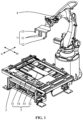
- Fig. 1 shows a schematic compositional and structural diagram of a cart remodeling system according to an embodiment of the present disclosure
- Fig. 2 shows a first schematic compositional and structural diagram of a jacking mechanism according to an embodiment of the present disclosure
- the cart remodeling system may include: a gripper mechanism 1 and a jacking mechanism 2.
- the gripper mechanism 1 is capable of being installed on a mechanical arm of a robot 4, the gripper mechanism 1 has a gripper assembly 11, and the gripper assembly 11 is used for picking or placing a position-limiting block 32 in a tray 31 arranged on the cart to be tested 3.
- the jacking mechanism 2 is arranged at a remodeling station for performing remodeling of the cart to be tested 3.
- the jacking mechanism 2 includes a jacking bracket 21 and a position-limiting assembly 22 arranged on the jacking bracket 21.
- the position-limiting assembly 22 is used for limiting a position of the cart to be tested 3 relative to the jacking mechanism 2.
- the cart remodeling system may be used for performing remodeling on the cart to be tested 3 that carries and transports a component to be transferred, so that the cart to be tested 3 matches the component to be transferred, and the component to be transferred is capable of being placed on the cart to be tested 3.
- the cart to be tested 3 can position and clamp the component to be transferred, thereby achieving smooth transportation of the component to be transferred.
- the cart to be tested 3 may be in a structural form including the tray 31, and the position-limiting block 32 is arranged on the tray 31.
- the component to be transferred may abut against the position-limiting block 32, the component to be transferred is supported by the position-limiting block 32 and the position of the component to be transferred is limited thereby, so that the component to be transferred is located in a fixed position on the tray 31.
- the component to be transferred may be a battery pack (Pack), a lower box body of the battery pack, and the like, so that the cart to be tested 3 may also be referred to as a "Pack Cart".
- Pack battery pack
- the cart to be tested 3 may also be referred to as a "Pack Cart”.
- the cart to be tested 3 may also be provided with a transport member, and the transport member may be a transport cart with a carrier frame and wheels, and the transport cart may travel on the road.
- the transport cart may be an unpowered transport cart, and the unpowered transport cart may be pulled by an Automated Guided Vehicle (AGV), so that the cart to be tested 3 can support the component to be transferred to a required location.
- AGV Automated Guided Vehicle
- the transport cart may also adopt the AGV, and the tray 31 is arranged on the AGV.
- the specific structure of the cart to be tested 3 is not limited in the embodiment of the present disclosure.
- the gripper mechanism 1 in order to replace the position-limiting block 32 arranged on the tray 31 or adjust the position of the position-limiting block 32 on the tray 31, the gripper mechanism 1 may be arranged, and the gripper mechanism 1 is provided with the gripper assembly 11 that is capable of gripping the position-limiting block 32.
- the gripper assembly 11 may be a structure including two gripping rods, and the gripping rods are movable to pick or place the position-limiting block 32.
- a connecting member that is capable of being adapted to the mechanical arm of the robot 4 may be arranged in the gripper mechanism 1, so that the gripper mechanism 1 may be mounted on the mechanical arm of the robot 4 through the connecting member.
- the robot 4 may adopt a six-axis robot, so that the gripper mechanism 1 is driven to move by the six-axis robot, thereby completing the movement of the position-limiting block 32.
- the position of the cart to be tested 3 needs to be limited so that the cart to be tested 3 is in a preset position.
- the jacking mechanism 2 may be arranged at the remodeling station for performing remodeling on the cart to be tested 3, and the jacking mechanism 2 may be configured in a structural form including the jacking bracket 21 and the position-limiting assembly 22.
- the jacking bracket 21 may be used for supporting and fixing the entire jacking mechanism 2, and the jacking mechanism 2 may be arranged at the remodeling station through the jacking bracket 21.
- the position-limiting assembly 22 may be arranged on the jacking bracket 21, and the position-limiting assembly 22 may be configured as a structure capable of generating movement. In a case that the cart to be tested 3 moves to the position where the jacking mechanism 2 is located, the position-limiting assembly 22 may be moved relative to the jacking bracket 21 so that the position-limiting assembly 22 abuts against the cart to be tested 3, and therefore, the cart to be tested 3 may be limited to the position where the jacking mechanism 2 is located.
- the gripper mechanism 1 is arranged in the cart remodeling system, and the gripper assembly 11 is arranged in the gripper mechanism 1, the position-limiting block 32 can be picked or the position-limiting block 32 can be placed through the gripper assembly 11.
- the gripper mechanism 1 may be mounted on the robot 4, and the robot 4 can drive the gripper mechanism 1 to move to drive the movement of the position-limiting block 32, so that the position-limiting block 32 on the cart to be tested 3 can be replaced, or the position of the position-limiting block 32 can be adjusted.
- the jacking mechanism 2 including the position-limiting assembly 22 is provided.
- the position of the cart to be tested 3 relative to the jacking mechanism 2 can be limited through the position-limiting assembly 22, thereby limiting the movement of the cart to be tested 3 so that the cart to be tested 3 can be parked at the preset position.
- it is conducive to quickly and accurately determining the position of the position-limiting block 32 that needs to be replaced, or quickly and accurately determining the position where the position-limiting block 32 to be placed is, so that it is conducive to controlling the robot 4 to drive the gripper mechanism 1 to quickly move to the required position, thereby improving the efficiency of the cart remodeling system in remodeling of the cart to be tested 3.
- Fig. 2 shows a first schematic compositional and structural diagram of a jacking mechanism according to an embodiment of the present disclosure
- Fig. 3 shows a second schematic compositional and structural diagram of a jacking mechanism according to an embodiment of the present disclosure
- Fig. 4 shows a schematic compositional and structural diagram of a jacking sleeve assembly according to an embodiment of the present disclosure.
- the jacking mechanism 2 in the cart remodeling system further includes a jacking sleeve assembly 23.
- the jacking sleeve assembly 23 includes a first driving member 231, a first connecting member 232, and a first nut recognition assembly 233.
- the first nut recognition assembly 233 is arranged on the jacking bracket 21; the first driving member 231 is fixed on the first nut recognition assembly 233, and the first connecting member 232 is drivingly connected to an output shaft of the first driving member 231.
- the first connecting member 232 is capable of moving in the direction close to a transverse transmission member 33 in the tray 31 and being connected to the transverse transmission member 33; and driven by the first driving member 231, the first connecting member 232 is capable of driving the transverse transmission member 33 to rotate.
- the transverse transmission member 33 extends in a first direction.
- m represents the first direction.
- a sleeve bracket 234 may be arranged in the jacking sleeve assembly 23, and the jacking sleeve assembly 23 is arranged on the jacking bracket 21 of the jacking mechanism 2 through the sleeve bracket 234.
- the first nut recognition assembly 233 may be configured in a structural form including a first sliding assembly 2331 and a sliding driving member 2332.
- the first sliding assembly 2331 may include a matching guide rail 23311 and a slider 23312.
- the guide rail 23311 is fixed on the sleeve bracket 234, and the slider 23312 is slidably connected to the guide rail 23311.
- the sliding driving member 2332 may adopt a driving cylinder, a cylinder barrel of the driving cylinder is connected to the sleeve bracket 234, and a piston rod of the driving cylinder is connected to the slider 23312.
- the first connecting member 232 may be a screwdriver bit adapted to the transverse transmission member 33 on the tray 31, and the first connecting member 232 may be sleeved on an end portion of a lead screw serving as the transverse transmission member 33 on the tray 31.
- the first connecting member 232 may be rotatably arranged on the slider 23312 in the first sliding assembly 2331.
- a bearing seat 235 is arranged on the slider 23312, the first connecting member 232 penetrates through an inner hole of an inner ring of a bearing located in the bearing seat 235, and the first connecting member 232 is rotatable.
- An axial direction of the first connecting member 232 may be set to be the same as an extending direction of the first sliding assembly 2331.
- the first driving member 231 may adopt a structural form of a servo motor and a reducer.
- the servo motor and the reducer are fixed on the slider 23312, and the reducer is connected to an output shaft of the servo motor, and then an output shaft of the reducer is drivingly connected to the first connecting member 232.
- the servo motor may be used to drive the reducer to rotate, so as to drive the first connecting member 232 to rotate.
- the first connecting member 232 is arranged in the jacking sleeve assembly 23 and the first driving member 231 drivingly connected to the first connecting member 232 is further arranged; therefore, the first connecting member 232 can be driven to rotate by the first driving member 231.
- the transverse transmission member 33 in the tray 31 that is sleeved with the first connecting member 232 can be driven to rotate, so that the position of the structural member in the tray 31 connected to the transverse transmission member 33 can be adjusted.
- the first connecting member 232 and the first driving member 231 are both arranged on the first nut recognition assembly 233.
- the first nut recognition assembly 233 can drive the first connecting member 232 to move in the direction close to the transverse transmission member 33 in the tray 31, so that the first connecting member 232 can be sleeved to the transverse transmission member 33. After completing the driving process of the transverse transmission member 33, the first connecting member 232 can also be driven by the first nut recognition assembly 233 to separate from the transverse transmission member 33. In this way, the position of the structural member in the tray 31 that needs to be moved can be quickly adjusted by the jacking sleeve assembly 23.
- the jacking mechanism 2 further includes a jacking assembly 24.
- the jacking assembly 24 includes a jacking driving member 241, a jacking transmission member 242, and a jacking beam 243.
- the jacking beam 243 is slidably connected to the jacking bracket 21, for supporting the cart to be tested 3.
- One end of the jacking driving member 241 is connected to the jacking bracket 21, and the other end is connected to the jacking transmission member 242.
- the jacking transmission member 242 is slidably arranged on the jacking bracket 21, and drivingly connected to the jacking beam 243.
- the jacking beam 243 may be arranged in the jacking assembly 24.
- the jacking beam 243 may be set as a strip-shaped columnar structure, and the columnar jacking beam 243 may be connected to the jacking bracket 21 in a sliding connection manner.
- slidingly connected guide rail and slider may be used, the guide rail is fixed on the jacking bracket 21, and the jacking beam 243 is fixedly connected to the slider, so that the jacking beam 243 is slidably connected to the jacking bracket 21.
- the jacking beam 243 may be configured as a structure that slides in the vertical direction, and two parallel jacking beams 243 may be arranged on the jacking bracket 21.
- the jacking transmission member 242 may be slidably arranged on the jacking bracket 21.
- a guide rail is fixedly arranged on the jacking bracket 21, and a chute adapted to the guide rail is arranged on the jacking transmission member 242, so that the jacking transmission member 242 may be slidably connected to the jacking bracket 21 through the chute and the guide rail.
- the jacking transmission member 242 may be configured as a wedge-shaped block structure with an inclined surface, and the inclined surface is drivingly connected to the jacking beam 243. Then, during the movement of the jacking transmission member 242 in its long axis direction, under the action of the inclined surface, the jacking beam 243 may be enabled to move in the vertical direction.
- the jacking driving member 241 may be configured as a structure including a driving cylinder, a cylinder barrel of the driving cylinder is connected to the jacking bracket 21, and a piston rod of the driving cylinder is connected to the jacking transmission member 242. Then the jacking transmission member 242 may be driven to move by driving the cylinder.
- the jacking assembly 24 is provided with the jacking beam 243 slidably connected to the jacking bracket 21, the jacking beam 243 can carry and support the cart to be tested 3; and the jacking transmission member 242 is slidably arranged on the jacking bracket 21.
- the jacking driving member 241 is arranged between the jacking transmission member 242 and the jacking bracket 21, and the jacking driving member 241 can drive the jacking transmission member 242 to move, thereby driving the jacking beam 243 to move in the vertical direction.
- the cart to be tested 3 when the cart to be tested 3 is in the position corresponding to the jacking mechanism 2, the cart to be tested 3 can be jacked by the jacking assembly 24 in the jacking mechanism 2, so that the cart to be tested 3 can move in the vertical direction, thereby allowing the cart to be tested 3 to be separated from the ground, so that the cart to be tested 3 is at the required height.
- the position-limiting assembly 22 in the jacking mechanism 2 includes a position-limiting driving member 221 and a position-limiting member 222.
- the position-limiting driving member 221 is fixed on the jacking bracket 21, and the position-limiting member 222 is connected on an output shaft of the position-limiting driving member 221.
- the position-limiting member 222 is capable of being connected to the cart to be tested 3 to limit the position of the cart to be tested 3 relative to the jacking mechanism 2.
- the position-limiting driving member 221 may be arranged in the position-limiting assembly 22, and the position-limiting driving member 221 may adopt a driving cylinder.
- the position-limiting member 222 may be configured in a structural form having a position-limiting bump.
- the position-limiting bump is fixed on a piston rod of the driving cylinder, and the position-limiting member 222 may be driven to move by the driving cylinder.
- a set of position-limiting assemblies 22 are respectively provided at both ends of the jacking bracket 21.
- the two position-limiting members 222 in the two sets of position-limiting assemblies 22 may be in contact with the front end and the rear end of the cart to be tested 3 respectively, thereby limiting the movement of the cart to be tested 3.
- the position-limiting driving member 221 is arranged in the position-limiting assembly 22, and the position-limiting member 222 may be driven by the position-limiting driving member 221 to move. Before the cart to be tested 3 moves into the jacking mechanism 2, the position-limiting member 222 may be driven by the position-limiting driving member 221 to move in a direction away from the center of the jacking mechanism 2, so as to facilitate the cart to be tested 3 to enter the interior of the jacking mechanism 2.
- the position-limiting member 222 may be driven by the position-limiting driving member 221 to move in the direction close to the cart to be tested 3 until the position-limiting member 222 abuts against the cart to be tested 3, which can limit the movement of the cart to be tested 3 relative to the jacking mechanism 2, thereby limiting the cart to be tested 3 to the preset position.
- a gripper sleeve assembly 12 may also be arranged in the gripper mechanism 1 of the cart remodeling system.
- the gripper sleeve assembly 12 includes a second driving member 121, a second connecting member 122, and a second nut recognition assembly 123.
- the second nut recognition assembly 123 and the second driving member 121 are both arranged on the mechanical arm of the robot 4; the second connecting member 122 is drivingly connected to the second nut recognition assembly 123, and the second connecting member 122 is drivingly connected to an output shaft of the second driving member 121.
- the second connecting member 122 is capable of moving in a direction close to the longitudinal transmission member 34 in the tray 31, and being connected to the longitudinal transmission member 34.
- the second driving member 121 the second connecting member 122 is capable of driving the longitudinal transmission member 34 to rotate.
- the longitudinal transmission member 34 extends in a second direction. Illustratively, as shown in Fig. 1 , n represents the second direction.
- the first direction m is the horizontal axis direction
- the second direction n is the vertical axis direction.
- the included angle between the first direction m and the second direction n is 90 degrees.
- a connecting bracket 124 may be arranged in the gripper sleeve assembly 12, and the gripper sleeve assembly 12 is arranged on the mechanical arm of the robot 4 through the connecting bracket 124.
- the second nut recognition assembly 123 may be configured in a structural form including a second sliding assembly 1231 and a nut recognition driving member 1232.
- the second sliding assembly 1231 may include a pulley 12311 and a spline shaft 12312.
- the pulley 12311 is rotatably arranged on the connecting bracket 124.
- a spline slot hole adapted to the spline shaft 12312 is arranged on the pulley 12311, and the spline shaft 12312 penetrates through the spline slot hole, and the spline shaft 12312 may slide in an axial direction of the spline slot hole.
- the nut recognition driving member 1232 may adopt a driving cylinder.
- a cylinder barrel of the driving cylinder is connected to the connecting bracket 124.
- a piston rod of the driving cylinder is rotationally connected to the other end of the spline shaft 12312.
- the piston rod may drive the spline shaft 12312 to reciprocate in an axial direction of the spline shaft 12312, and the spline shaft 12312 may still rotate, but the piston rod will not rotate together with the spline shaft 12312.
- the second connecting member 122 may be a screwdriver bit adapted to the longitudinal transmission member 34 on the tray 31, and the second connecting member 122 may be sleeved on an end portion of a lead screw serving as the longitudinal transmission member 34 on the tray 31.
- the second connecting member 122 may be connected to the spline shaft 12312, for example, the second connecting member 122 is fixedly mounted on one end of the spline shaft 12312. Therefore, the second connecting member 122 may be driven by the second nut recognition assembly 123 to move in a direction closer to the longitudinal transmission member 34.
- the second driving member 121 may adopt a structural form of a servo motor and a reducer.
- the servo motor and the reducer are fixed on the connecting bracket 124, and the reducer is connected to an output shaft of the servo motor, and then an output shaft of the reducer is drivingly connected to the pulley 12311.
- the servo motor may be used to drive the reducer to rotate, so as to drive the pulley 12311 to rotate, thereby driving the second connecting member 122 to rotate.
- the second connecting member 122 is arranged in the gripper sleeve assembly 12 and the second driving member 121 drivingly connected to the second connecting member 122 is further arranged; therefore, the second connecting member 122 can be driven to rotate by the second driving member 121.
- the longitudinal transmission member 34 in the tray 31 that is sleeved with the second connecting member 122 can be driven to rotate, so that the position of the structural member in the tray 31 connected to the longitudinal transmission member 34 can be adjusted.
- the second connecting member 122 is arranged on the second nut recognition assembly 123.
- the second nut recognition assembly 123 can drive the second connecting member 122 to move in the direction close to the longitudinal transmission member 34 in the tray 31, so that the second connecting member 122 can be sleeved to the longitudinal transmission member 34. After completing the driving process of the longitudinal transmission member 34, the second connecting member 122 can also be driven by the second nut recognition assembly 123 to separate from the longitudinal transmission member 34. In this way, the position of the other structural member in the tray 31 that needs to be moved can be quickly adjusted by the gripper sleeve assembly 12.
- the gripper mechanism 1 of the cart remodeling system may be further provided with a visual detection system 13, and the visual detection system 13 is capable of being electrically coupled to a controller.
- the visual detection system 13 is used for taking photographs of a site to be picked and a site to be placed, and performing offset compensation on positions of the site to be picked and the site to be placed.
- the visual detection system 13 may be arranged in the gripper mechanism 1, and an accurate target position of the position to which the gripper assembly 11 is to be moved is determined through the visual detection system 13.
- the visual detection system 13 may be connected to the controller in a wired or wireless manner.
- the controller may be a lower computer in the production line, such as a Programmable Logic Controller (PLC), which is a computer device capable of being used for controlling movements of various components.
- PLC Programmable Logic Controller
- the visual detection system 13 may be configured as a structure including a Charge Coupled Device (CCD) camera.
- CCD Charge Coupled Device
- the CCD camera may be used to take photographs of the site to be picked where the position-limiting block 32 is located, and the captured image of the site to be picked may be used to calculate and determine a first offset of the site to be picked, so that offset compensation may be performed on the site to be picked based on the first offset.
- the target position of the site to be picked may be determined according to the first offset and the site to be picked, and then the movement of the robot 4 may be controlled to drive the gripper assembly 11 in the gripper mechanism 1 to move to the target position of the site to be picked.
- the CCD camera may be used to take photographs of the site to be placed where the position-limiting block 32 is located, and the captured image of the site to be placed may be used to calculate and determine a second offset of the position where the position-limiting block 32 is to be placed, so that offset compensation may be performed on the site to be placed based on the second offset.
- the target position of the site to be placed may be determined according to the second offset and the site to be placed, and then the movement of the robot 4 may be controlled to drive the gripper assembly 11 in the gripper mechanism 1 to move to the target position of the site to be placed.
- the visual detection system 13 is arranged on the gripper mechanism 1, and therefore, the positions of the site to be picked and the site to be placed may be visually guided and corrected by the visual detection system 13.
- the information of the target position that the gripper assembly 11 in the gripper mechanism 1 is to reach is capable of being determined, so that the gripper assembly 11 may be controlled to move to the target position according to the determined target position, and the gripper assembly 11 may then be moved to an accurate picking position or placement position, thereby improving the efficiency of replacement or position adjustment of the position-limiting block 32 on the tray 31.
- Fig. 6 is a first schematic flowchart of a cart remodeling control method according to an embodiment of the present application.
- the method may include: S601: Acquire, when a cart to be tested reaches a preset position, current blueprint information of the cart to be tested.
- the method may be applied to a controller.
- the controller may be a lower computer PLC in the production line. Using the PLC to realize automatic remodeling of the cart to be tested may reduce labor costs and production costs, so that the production efficiency is higher.
- a tray is placed on an upper surface of the cart to be tested, and the tray is used for carrying a component to be transferred.
- the cart to be tested is used as a transfer apparatus, which can transfer a component of the previous process to the next process for processing, assembling, and the like.
- At least one position-limiting block is arranged on the tray, and the at least one position-limiting block is used for limiting the position of the component to be transferred on the tray.
- the component to be transferred may be a battery pack, a box body (in particular, a lower box body) of the battery pack, or the like, so that the cart to be tested may also be referred to as a "Pack Cart".
- the cart to be tested may be pulled and moved by an automated guided vehicle.
- the method before the cart to be tested reaches a preset position, the method further includes: receiving an entry request sent by the automated guided vehicle; and sending, based on the entry request, an entry permit instruction to the automated guided vehicle.
- the entry permit instruction is used to instruct the automated guided vehicle to pull the cart to be tested to move until the cart to be tested reaches the preset position.
- the automated guided vehicle sends the entry request to the controller; after the controller allows entry, the automated guided vehicle may pull the cart to be tested into a remodeling station.
- the automated guided vehicle travels along a predetermined route, and a sensor chip is arranged at the preset position.
- a sensing apparatus of the cart to be tested will receive a signal sent by the sensor chip, which means that the automated guided vehicle is in place, that is, the cart to be tested reaches the preset position.
- the electronic tag may be a Radio Frequency Identification (RFID) chip, which is specifically placed on a lower surface of the tray.
- RFID Radio Frequency Identification
- S602 Receive target blueprint information sent by a manufacturing execution system, and match the current blueprint information with the target blueprint information for consistency.
- the target blueprint information may be sent to the controller by a Manufacturing Execution System (MES).
- MES Manufacturing Execution System
- the MES system is deployed in the upper computer or server.
- the MES system is used for acquiring output information of a plurality of production devices.
- the output information includes output time of a plurality of products produced by the production device and identifications used for indicating whether the plurality of products are qualified.
- the MES system includes monitoring of the production process.
- the monitoring of the production process of the MES system focuses on monitoring of material transportation and quality indicators between a production process and a technological process. It is based on real-time data of the production process and uses the configuration technology of the MES system to realize real-time monitoring of the production progress, process quality, and material consumption in production areas such as a production workshop, a power and energy workshop, an auxiliary material warehouse, and a finished product warehouse.
- the production process monitoring system When the production process monitoring system detects an abnormality, it may issue an alarm according to preset settings, thereby helping a production command and dispatch department of an enterprise perform production coordination and rational dispatch, and improving the rapid response ability of production.
- the MES system organizes and coordinates production according to the production process characteristics of various industries, tracks production process data, and assesses various production indicators; and through data analysis, optimizes the production process, realizes plan preparation and tracking, production data analysis, assessment management, and the like. Managers are capable of grasping the input and output of the entire factory in real time and optimizing production decisions, thereby minimizing production time, reducing errors, and reducing costs related to manual and repeated data entry as much as possible.
- the main functions include production plan management, production organization, workshop assessment and personnel management, production data analysis, and other subsystems.
- the automatic remodeling of the cart to be tested mainly refers to automatic switching of formulas.
- the manual selection function is retained, but also an automatic issuing function of the MES system is added.
- Data security can be improved by distributing target blueprint information through the MES system.
- the current blueprint information and the target blueprint information may be matched for consistency. If the two are consistent, the cart to be tested may be released directly; and if the two are inconsistent, the cart to be tested needs to be remodeled automatically, or requires switching the formula automatically.
- S603 Control, when the current blueprint information is inconsistent with the target blueprint information, a jacking mechanism to perform positioning and jacking actions on the cart to be tested, and then send a control instruction to a robot; wherein the control instruction is used for controlling a gripper mechanism arranged on the robot to perform a pick-and-place action on at least one position-limiting block on the tray.
- the tray is located on the upper surface of the cart to be tested.
- the at least one position-limiting block has the function of position-limiting and supporting the component to be transferred.
- the at least one position-limiting block can not only limit the position of the component to be transferred on the tray, but also play a role in supporting the component to be transferred on the tray.
- the formula may be used to memorize the position-limiting block position.
- the automatic switching of the formula here specifically refers to automatic replacement of the position-limiting block position according to the target blueprint information corresponding to the formula, so as to realize the automatic remodeling of the cart to be tested.
- the jacking mechanism may include a position-limiting assembly, a positioning assembly, and a jacking assembly.
- the method may include:
- the position-limiting assembly is used for limiting the position of the cart to be tested relative to the jacking mechanism.
- the controller controls the position-limiting assembly on the jacking mechanism to perform the position-limiting action so that the cart to be tested stays at the preset position.
- the position-limiting assembly may include a position-limiting driving member and a position-limiting member.
- the position-limiting driving member may be a front-and-rear clamping cylinder fixed on the jacking mechanism, and the position-limiting member is a cart clamping mechanism (or referred to as a "cart clamping block") connected to the front-and-rear clamping cylinder.
- the front-and-rear clamping cylinder may be extended to drive the cart clamping mechanism to clamp the cart to be tested, thereby controlling the cart to be tested to stay at the preset position to realize rough positioning of the cart to be tested.
- the controller controls the positioning assembly to perform the positioning action, and controls the jacking assembly to perform the jacking action, so as to complete the positioning and jacking actions of the jacking mechanism on the cart to be tested.
- the positioning assembly may be a positioning pin cylinder fixed on the jacking mechanism
- the jacking assembly may be a jacking cylinder fixed on the jacking mechanism.
- the driving member may include a first driving member arranged in a jacking sleeve assembly on the jacking mechanism
- the transmission member may include a transverse transmission member arranged in the tray.
- the method further includes: S703: Control the jacking sleeve assembly on the jacking mechanism to perform a nut recognition action so that the first driving member is connected to the transverse transmission member through a first connecting member in the jacking sleeve assembly, and control the first driving member to drive the first connecting member to rotate, so as to drive, through the first connecting member, the transverse transmission member to move to an initial position of the transverse transmission member.
- the first driving member may be a first servo motor
- the first connecting member may be a first screwdriver bit (or referring to a first sleeve).
- the jacking sleeve assembly may include the first servo motor and the first screwdriver bit connected to a rotation shaft of the first servo motor.
- the transverse transmission member may be a first lead screw, and the transverse transmission member extends in the first direction.
- the controller may control a sleeve cylinder on the jacking mechanism to extend and perform a nut recognition function so that the first screwdriver bit is aligned with the first lead screw.
- the entire jacking sleeve assembly may be moved in a direction of the axial direction of the rotation shaft towards a direction close to the first lead screw, so that the first screwdriver bit and the first lead screw are sleeved.
- the controller controls the first servo motor to drive the first screwdriver bit to rotate, so as to drive, through the first screwdriver bit, the first lead screw to move to an initial position of the first lead screw.
- the driving member may also include a second driving member arranged in the gripper sleeve assembly on the gripper mechanism, and the transmission member may further include a longitudinal transmission member arranged in the tray.
- the method further includes:
- the second driving member may be a second servo motor
- the second connecting member may be a second screwdriver bit (or referring to a second sleeve).
- the gripper sleeve assembly may include the second servo motor and the second screwdriver bit connected to a rotation shaft of the second servo motor.
- the longitudinal transmission member may be a second lead screw, and the longitudinal transmission member extends in the second direction.
- the first direction is the horizontal axis direction
- the second direction is the vertical axis direction.
- the included angle between the first direction and the second direction is 90 degrees.
- a first position of the robot is an origin of the robot, and a second position of the robot is a rotation working position of the longitudinal transmission member.
- the controller allows the second driving member to work, the robot needs to be started first and then moved to the rotation working position of the second lead screw.
- the controller may control a sleeve on the gripper mechanism to perform a nut recognition function so that the second screwdriver bit is aligned with the second lead screw.
- the entire gripper sleeve assembly is capable of being moved in a direction of the axial direction of the rotation shaft towards the second lead screw, so that the second screwdriver bit and the second lead screw are sleeved.
- the controller controls the second servo motor to drive the second screwdriver bit to rotate, so as to drive, through the second screwdriver bit, the second lead screw to move to an initial position of the second lead screw.
- the target blueprint information issued by the MES system may also be used to make error-proof and fool-proof judgments.
- the method before sending the control instruction to the robot, the method further includes: receiving a position-limiting block position fed back by the robot; sending the control instruction to the robot if the position-limiting block position fed back by the robot is consistent with the position-limiting block position in the target blueprint information; wherein the position-limiting block position indicates a hole site serial number corresponding to the position-limiting block to be picked and placed by the robot.
- the controller may notify the gripper mechanism of the robot to pick the position-limiting block with a certain hole site serial number based on the position-limiting block position in the target blueprint information; and before picking, the robot may further provide feedback to the controller the current hole site serial number to be picked. Then, consistency calibration is performed. Only when the two are consistent, the controller sends the control instruction to the robot, which prevents the robot from picking a position-limiting block with a wrong hole site serial number.
- the controller may send a control instruction to the robot at this time. Specifically, it may include:
- the visual detection system is specifically arranged on the gripper mechanism of the robot.
- the visual detection system is a structure including a CCD camera, and therefore, the visual detection system may be referred to as a "CCD camera”, or also may be referred to as a "gripper camera”.
- the specific method may be as follows: after the visual detection system on the robot is moved to a photographing position of the site to be picked, the controller may send the first photographing instruction to the robot; wherein the first photographing instruction is used for instructing the visual detection system to take a photograph of the site to be picked; after the visual detection system completes the photographing of the site to be picked, the visual detection system is controlled to calculate according to the photographed first image, so as to determine a first offset of the site to be picked; then an initial position of the site to be picked is compensated based on the first offset to determine a target position of the site to be picked; and then the controller sends a first picking instruction to the robot to control the gripper mechanism to move to the site to be picked, and after moving to the target position of the site to be picked, the gripper mechanism is controlled based on the first picking instruction to pick the position-limiting block on the site to be picked.
- Fig. 8 is a schematic structural top view of a site to be picked according to an embodiment of the present application.
- the first offset at this time may include: an offset in an X-axis direction being -0.457, an offset in a Y-axis direction being -0.483, and an angle offset being 0.406.
- the specific method may be as follows: after the visual detection system on the robot is moved to a photographing position of the site to be placed, the controller may send the second photographing instruction to the robot; wherein the second photographing instruction is used for instructing the visual detection system to take a photograph of the site to be placed; after the visual detection system completes the photographing of the site to be placed, the visual detection system is controlled to calculate according to the photographed second image, so as to determine a second offset of the site to be placed; then an initial position of the site to be placed is compensated based on the second offset to determine a target position of the site to be placed; and then the controller sends a first placing instruction to the robot to control the gripper mechanism to move to the site to be placed, and after moving to the target position of the site to be placed, the gripper mechanism is controlled based on the first placing instruction to place the position-limiting block to the site to be placed.
- Fig. 9 is a schematic structural top view of a site to be placed according to an embodiment of the present application.
- the second offset at this time may include: an offset in an X-axis direction being -0.623, an offset in a Y-axis direction being 0.253, and an angle offset being -0.033.
- the controller can control the visual detection system to perform visual guide for offset correction on the picking position or placing position, and is capable of accurately determining, according to the corresponding offset data, a target position that the gripper assembly in the gripper mechanism intends to reach, so that according to the determined target position, the controller can control the gripper assembly to move to the target position, and therefore, the gripper assembly can move to the accurate picking position or placing position to perform pick-and-place on the position-limiting block.
- S604 Determine, when a position of the at least one position-limiting block matches a position-limiting block position in the target blueprint information, that remodeling of the cart to be tested is successful, and control the jacking mechanism to perform a releasing action to release the cart to be tested.
- the driving member after determining that the remodeling of the cart to be tested is successful, it further needs to control the driving member to perform a second driving action to drive the transmission member to move to an axial positioning position in the target blueprint information.
- the second driving action may be a reverse action of the first driving action.
- the first driving action instructs the driving member to drive the transmission member to move in a first axial direction
- the second driving action instructs the driving member to drive the transmission member to move in an opposite direction of the first axial direction.
- the driving member is controlled to perform the second driving action to drive the transmission member to return to the axial positioning position in the target blueprint information.
- the method may include:
- the axial positioning position includes a positioning position in the first direction and a positioning position in the second direction.
- the positioning position in the first direction may be the X-axis positioning position
- the positioning position in the second direction may be the Y-axis positioning position.
- the gripper sleeve assembly of the robot performs the nut recognition action
- the second driving member that is, the second servo motor
- the gripper sleeve assembly is controlled to perform the separation action to separate the second lead screw from the corresponding screwdriver bit; and after the second lead screw moves in place, it is necessary to control the robot to return to the first position (that is, the origin of the robot).
- the first driving member that is, the first servo motor
- the first driving member performs absolute position positioning to move the first lead screw to the X-axis positioning position of the target blueprint information
- the jacking sleeve assembly is controlled to perform the separation action so that the first lead screw is separated from the corresponding screwdriver bit.
- the method further includes:
- the jacking mechanism when the cart to be tested is successfully remodeled, when the jacking mechanism is controlled to perform the releasing action, it may include: controlling the positioning assembly, the jacking assembly, and the position-limiting assembly to respectively perform the releasing action, that is, controlling a positioning pin cylinder on the jacking mechanism to retract and a jacking cylinder to retract, and then controlling the front-and-rear cylinder on the jacking mechanism to retract, so as to release the cart to be tested.
- the cart to be tested when the cart to be tested is released, it may also include: clearing station data, and pulling the cart to be tested away from the station by the AGV.
- the method may further include:
- the target blueprint information may also be written into the electronic tag on the cart to be tested, then the newly written blueprint information may be re-identified through the RFID, and the newly written blueprint information may be verified together with the target blueprint information issued by the MES system. If the two are consistent, it is confirmed that the electronic tag is written successfully, and the cart to be tested is allowed to be released.
- the method further includes: controlling the jacking mechanism to perform a releasing action to release the cart to be tested.
- the jacking mechanism when the jacking mechanism is controlled to perform the releasing action, it may include: controlling the position-limiting assembly to perform the releasing action, that is, controlling the front-and-rear cylinder on the jacking mechanism to retract, so as to release the cart to be tested.
- the present embodiment provides a cart remodeling control method, specifically an automatic cart remodeling control solution that can automatically select the corresponding formula, automatically identify the cart type, and visually correct deviations, and is error-proof and fool-proof.
- the controller controls the jacking mechanism to perform positioning and jacking actions on the cart to be tested, and then the robot controls the gripper mechanism to perform a pick-and-place action on at least one position-limiting block on the tray; and when the position of the at least one position-limiting block matches the position-limiting block position in the target blueprint information, it is determined that the remodeling of the cart to be tested is successful, and the cart is released.
- the blueprint information may be automatically issued by the manufacturing execution system and recognized through the electronic tag, which improves the data security; on the other hand, remodeling performed on the cart has been changed from manual replacement to automatic replacement, and the robot is simple in a remodeling logic, there is no need to configure a plurality of sensors, and it further improves the degree of automation of the devices, while reducing the labor costs and production costs, thereby improving the production efficiency during product remodeling.
- controlling the lead screw displacement in the tray and performing the pick-and-place action on the at least one position-limiting block on the tray can also adapt to components to be transferred with different specifications and parameters, thereby improving the compatibility.
- the cart remodeling control method based on the previous embodiment, taking the pack cart as an example, is mainly applied in the field of pack automatic assembling, especially the automatic remodeling station of the pack cart.
- Fig. 11 which is a schematic detailed flowchart of a cart remodeling control method according to an embodiment of the present application. As shown in Fig. 11 , the detailed process may include:
- S1117 is performed, that is, the front-and-rear clamping cylinder retracts, and the cart to be tested leaves the station; and if the judgment result is inconsistent, S1106 to S1116 are performed until the cart to be tested is released and the station data is cleared.
- an automatic cart remodeling control solution that can realize rapid cutting and pulling functions is provided here, which may realize, by controlling the robot through the PLC, multi-functional system controls on the cart to be tested such as lead screw pitch change, position-limiting block replacement, and automatic formula switching.
- the rapid cutting and pulling functions are mainly reflected in: on the one hand, the manual replacement of the position-limiting block is changed to the automatic replacement by the robot; on the other hand, the formula modification is changed to automatically issuing the target blueprint information by the MES system.
- the position-limiting block may also be referred to as the positioning block, which use a polyoxymethylene (POM) material, and therefore, the position-limiting block may also be referred to as a "POM block”.
- POM polyoxymethylene
- the embodiment of the present disclosure provides an automatic pack cart remodeling control solution that can automatically select the corresponding formula, automatically identify the cart type, and visually correct deviations, and is error-proof and fool-proof.
- the formula may be matched with the blueprint information issued by the MES system and the blueprint information read by the electronic tag. If they are consistent, automatic releasing is performed; and if they are inconsistent, automatic remodeling is performed.
- the manual replacement is changed to automatic replacement, the robot is simple in the remodeling logic and is fully automated and unattended, and the replacement of the position-limiting block position may be identified, determined, and guided by the visual detection system.
- the structure is simple and the logic is clear, and there is no need to configure a plurality of sensors.
- the automatic issuing function of the MES system is added.
- the front-and-rear workstations and the pack cart remodeling station operate in parallel, which greatly improves the efficiency. That is, in multi-station production, there is no need to wait for the cart remodeling time.
- using the servo motor to rotate the lead screw to change the pitch and replace the position-limiting block position is capable of adapting to all box body sizes of existing products and has good compatibility.
- the offset data is provided through the visual detection system on the robot, as shown in Fig. 8 and Fig. 9 specifically, the position-limiting block position may also be automatically identified and corrected based on vision, which is capable of adapting to different blueprint information, sizes, heights, and other requirements, which improves the production efficiency during product remodeling.
- Fig. 12 is a schematic diagram of a network framework of an automatic remodeling station according to an embodiment of the present disclosure.
- the network framework 120 may include the robot 4, a valve island 1201, a distributed input and output module 1202, a visualization device 1203, a remote input and output module 1204, a servo controller 1205, a PLC controller 1206, an MES server 1207, a visual detection system 13, and a video monitoring system 1208.
- the robot 4 may be a six-axis robot
- the visualization device 1203 may be a Human Machine Interface (HMI) device.
- HMI Human Machine Interface
- the servo controller 1205 includes a servo driver 12051 and a servo motor 12052.
- the PLC controller 1206 may drive, through the servo driver 12051, the servo motor 12052 to work.
- the visual detection system 13 includes a visual host 131 and a CCD camera 132.
- the PLC controller 1206 may send a photographing instruction to the CCD camera 132 through the visual host 131.
- the video monitoring system 1208 includes a monitoring host 12081, a camera 12082, and a monitor 12083.
- the PLC controller 1206 may also control, through the monitoring host 12081, the camera 12082 to rotate and send the photographing instruction.
- the captured image may be displayed on the monitor 12083.
- the thick black line in Fig. 12 represents an automation bus (Profinet) communication method
- the dotted line in Fig. 12 represents an Ethernet bus (Ethernet) communication method
- the dashed line in Fig. 12 represents a Universal Serial Bus (USB)/serial communication method.
- Profilet automation bus
- Ethernet Ethernet bus
- USB Universal Serial Bus
- the PLC controller 1206 is based on the Profinet communication method and may communicate with the robot 4, the valve island 1201, the distributed input and output module 1202, the visualization device 1203, the remote input and output module 1204, and the servo controller 1205.
- the PLC controller 1206 is based on the Ethernet communication method and may communicate with the MES server 1207, the visual detection system 13, and the video monitoring system 1208.
- protocol methods included in the network topology may be seen in Table 1 for details.
- Table 1 MES server to stay server Open protocol Device server to station (PLC or station PC) S7 protocol or open protocol Station to AGV server S7 protocol or open protocol AGV server to AGV Wireless communication
- the S7 protocol is a communication protocol integrated within the Siemens S7 series PLC. It is a specially optimized communication protocol that runs on the transport layer (session layer/presentation layer/application layer). Its information transmission may be based on a parallel computing communication protocol (Message Passing Interface, MPI) network, a PROcess FIeld BUS (PROFIBUS) network, or the Ethernet.
- MPI Message Passing Interface
- PROFIBUS PROcess FIeld BUS
- Ethernet Ethernet
- the S7 protocol is the standard protocol used for communication between Siemens S7 series products. Its advantage is that both communicating parties may establish communication through the S7 protocol whether they are on the same MPI bus, the same PROFIBUS bus, or the same industrial Ethernet.
- the technical solutions of the embodiments of the present disclosure may make the device more automated (from manual replacement to machine replacement), data security is improved (blueprint information is issued through the MES system and electronic label identification), the efficiency is higher (manpower and cycle time of remodeling are reduced), and the compatibility is better (by controlling the pitch change of the lead screw in the tray and performing the pick-and-place action on the at least one position-limiting block on the tray, the components to be transferred with different specifications and parameters are capable of being adapted).
- the term "include”, “comprise”, or other variations thereof are intended to cover non-exclusive including, so that a process, a method, an article, or an apparatus including a series of elements not only includes the elements, but also includes other elements not clearly listed, or further includes inherent elements of the process, method, article, or apparatus.
- an element defined by “including a" does not exclude that the process, method, article, or apparatus including the element further has other identical elements.
- the current blueprint information of the cart to be tested is matched with the target blueprint information for consistency; if the current blueprint information is inconsistent with the target blueprint information, it is determined to perform remodeling automatically for the cart to be tested, specifically: first, control the jacking mechanism to perform positioning and jacking actions on the cart to be tested, and then send the control instruction to the robot to control the gripper mechanism arranged on the robot to perform the pick-and-place action on the at least one position-limiting block on the tray; and when the position of the at least one position-limiting block matches the position-limiting block position in the target blueprint information, determine that the remodeling of the cart to be tested is successful.
Landscapes
- Engineering & Computer Science (AREA)
- Manufacturing & Machinery (AREA)
- Physics & Mathematics (AREA)
- General Physics & Mathematics (AREA)
- Automation & Control Theory (AREA)
- Mechanical Engineering (AREA)
- Robotics (AREA)
- Human Computer Interaction (AREA)
- General Engineering & Computer Science (AREA)
- Quality & Reliability (AREA)
- Manipulator (AREA)
Applications Claiming Priority (2)
| Application Number | Priority Date | Filing Date | Title |
|---|---|---|---|
| CN202311303894.7A CN117021124B (zh) | 2023-10-10 | 2023-10-10 | 小车换型控制方法以及系统 |
| PCT/CN2023/139613 WO2025077004A1 (zh) | 2023-10-10 | 2023-12-18 | 小车换型控制方法以及系统 |
Publications (2)
| Publication Number | Publication Date |
|---|---|
| EP4570451A1 true EP4570451A1 (de) | 2025-06-18 |
| EP4570451A4 EP4570451A4 (de) | 2025-06-18 |
Family
ID=95252960
Family Applications (1)
| Application Number | Title | Priority Date | Filing Date |
|---|---|---|---|
| EP23892789.1A Pending EP4570451A4 (de) | 2023-10-10 | 2023-12-18 | Wagenwechselsteuerungsverfahren und wagenwechselsystem |
Country Status (2)
| Country | Link |
|---|---|
| US (1) | US20250116985A1 (de) |
| EP (1) | EP4570451A4 (de) |
Family Cites Families (1)
| Publication number | Priority date | Publication date | Assignee | Title |
|---|---|---|---|---|
| CN110682271B (zh) * | 2019-09-03 | 2023-04-04 | 贵州航天电器股份有限公司 | 一种用于圆形连接器生产线载具更换销钉的设备及方法 |
-
2023
- 2023-12-18 EP EP23892789.1A patent/EP4570451A4/de active Pending
-
2024
- 2024-09-20 US US18/892,032 patent/US20250116985A1/en active Pending
Also Published As
| Publication number | Publication date |
|---|---|
| US20250116985A1 (en) | 2025-04-10 |
| EP4570451A4 (de) | 2025-06-18 |
Similar Documents
| Publication | Publication Date | Title |
|---|---|---|
| EP3778115B1 (de) | Automatische werkzeugwechselvorrichtung mit agv als tragvorrichtung | |
| CN117021124B (zh) | 小车换型控制方法以及系统 | |
| CN107234615B (zh) | 工件摆放系统、工件放置装置及工件摆放控制方法 | |
| WO2021050646A1 (en) | Robot-mounted moving device, system, and machine tool | |
| CN117021125B (zh) | 一种匹配控制方法以及系统 | |
| CN106737688B (zh) | 一种基于多传感器的集箱管座机器人自动装配系统和方法 | |
| CN108858218B (zh) | 一种适应自动物流的机械臂制孔装置及制孔方法 | |
| CN110711934A (zh) | 一种搅拌摩擦焊设备及工艺 | |
| JP7797558B2 (ja) | ロボット搭載移動装置、及びその制御方法 | |
| CN118678641A (zh) | 一种smt自动贴片装置控制系统 | |
| EP4570451A1 (de) | Wagenwechselsteuerungsverfahren und wagenwechselsystem | |
| CN115697653A (zh) | 图像处理方法、图像处理装置、机器人搭载型输送装置以及系统 | |
| CN217786951U (zh) | 一种自动检测多种工件的x射线数字成像设备 | |
| CN116652697A (zh) | 智能柔性加工系统及其加工方法 | |
| CN114260579B (zh) | 一种发动机连杆自动刻码设备 | |
| CN217250816U (zh) | 一种多模块综合实训台 | |
| JP6832408B1 (ja) | 生産システム | |
| CN120228537A (zh) | 一种电池包自动拧紧方法、系统、电子设备及存储介质 | |
| CN210549493U (zh) | 自动化加工系统 | |
| CN111442774A (zh) | 利用agv的智能移换平台实现自动交换的方法及系统 | |
| CN215432736U (zh) | 一种自动上下料多功能夹具 | |
| CN113910002B (zh) | 双主轴双y轴复合数控机床的加工方法 | |
| CN216326428U (zh) | 一种车基面气门芯一体机 | |
| CN215091275U (zh) | 半挂车龙门架生产线 | |
| CN117754324A (zh) | 油缸锻件加工装置及方法 |
Legal Events
| Date | Code | Title | Description |
|---|---|---|---|
| STAA | Information on the status of an ep patent application or granted ep patent |
Free format text: STATUS: UNKNOWN |
|
| STAA | Information on the status of an ep patent application or granted ep patent |
Free format text: STATUS: THE INTERNATIONAL PUBLICATION HAS BEEN MADE |
|
| PUAI | Public reference made under article 153(3) epc to a published international application that has entered the european phase |
Free format text: ORIGINAL CODE: 0009012 |
|
| STAA | Information on the status of an ep patent application or granted ep patent |
Free format text: STATUS: REQUEST FOR EXAMINATION WAS MADE |
|
| 17P | Request for examination filed |
Effective date: 20240531 |
|
| A4 | Supplementary search report drawn up and despatched |
Effective date: 20250402 |
|
| AK | Designated contracting states |
Kind code of ref document: A1 Designated state(s): AL AT BE BG CH CY CZ DE DK EE ES FI FR GB GR HR HU IE IS IT LI LT LU LV MC ME MK MT NL NO PL PT RO RS SE SI SK SM TR |
|
| STAA | Information on the status of an ep patent application or granted ep patent |
Free format text: STATUS: EXAMINATION IS IN PROGRESS |
|
| 17Q | First examination report despatched |
Effective date: 20251218 |