EP4570221A1 - Produktionslinie zur herstellung von sanitärprodukten wie absorbierenden produkten für den sanitärgebrauch - Google Patents
Produktionslinie zur herstellung von sanitärprodukten wie absorbierenden produkten für den sanitärgebrauch Download PDFInfo
- Publication number
- EP4570221A1 EP4570221A1 EP24202224.2A EP24202224A EP4570221A1 EP 4570221 A1 EP4570221 A1 EP 4570221A1 EP 24202224 A EP24202224 A EP 24202224A EP 4570221 A1 EP4570221 A1 EP 4570221A1
- Authority
- EP
- European Patent Office
- Prior art keywords
- production line
- mod1
- modn
- mod2
- panels
- Prior art date
- Legal status (The legal status is an assumption and is not a legal conclusion. Google has not performed a legal analysis and makes no representation as to the accuracy of the status listed.)
- Pending
Links
Images

Classifications
-
- A—HUMAN NECESSITIES
- A61—MEDICAL OR VETERINARY SCIENCE; HYGIENE
- A61F—FILTERS IMPLANTABLE INTO BLOOD VESSELS; PROSTHESES; DEVICES PROVIDING PATENCY TO, OR PREVENTING COLLAPSING OF, TUBULAR STRUCTURES OF THE BODY, e.g. STENTS; ORTHOPAEDIC, NURSING OR CONTRACEPTIVE DEVICES; FOMENTATION; TREATMENT OR PROTECTION OF EYES OR EARS; BANDAGES, DRESSINGS OR ABSORBENT PADS; FIRST-AID KITS
- A61F13/00—Bandages or dressings; Absorbent pads
- A61F13/15—Absorbent pads, e.g. sanitary towels, swabs or tampons for external or internal application to the body; Supporting or fastening means therefor; Tampon applicators
- A61F13/15577—Apparatus or processes for manufacturing
- A61F13/15804—Plant, e.g. involving several steps
- A61F2013/15813—Plant, e.g. involving several steps with modular lines
Definitions
- the present invention concerns the technical field regarding a production line for realizing sanitary products, preferably wearable sanitary products such as for example pads for men, women or children, handkerchiefs for example for face use, etc., and/or in particular absorbent products for sanitary use.
- sanitary products preferably wearable sanitary products such as for example pads for men, women or children, handkerchiefs for example for face use, etc., and/or in particular absorbent products for sanitary use.
- the invention refers to a production line that, overall, is very flexible in its composition and/or realization, resulting at the same time in a structure that, in addition to being versatile, is also safe for the operators by guaranteeing safe access to its operative or control areas and further guaranteeing easy access to said areas.
- sanitary products for example absorbent products for sanitary use
- the sanitary products that can be realized are manifold and may include sanitary products that can be worn by a user, such as for example the products belonging to the category of disposable diapers, disposable pads, disposable sanitary pads, handkerchiefs, leakage protection mattress covers, etc.
- these production lines are developed through manufacturing sections or manufacturing stations as it may be (also defined herein with the term of manufacturing units or simply units) that are connected to each other in succession.
- manufacturing sections or manufacturing stations as it may be (also defined herein with the term of manufacturing units or simply units) that are connected to each other in succession.
- sanitary products can be realized by starting even from supplying, to the production line, raw materials and then obtaining the finished and even packaged product coming out of the line.
- sanitary products such as the category of the disposable diapers (or similar)
- it is started by processing the cellulose that forms the "absorbent core" of the product and which is trapped between the two sheets of material that is generated by unwinding the master reels.
- the product is made through manufacturing steps that are carried out in succession in the various manufacturing stations (or units as it may be as said) until the finished product is completed, which can even be packaged at the end of the forming process thereof.
- each unit actually, houses one or a series of operative apparatuses that is/are used to carry out a certain manufacturing step.
- the operative apparatus may for example provide a motor and an operative part which is driven by said motor to perform a certain operation.
- the operative part may for example comprise rollers that are driven in rotation to perform a certain manufacturing step on the product.
- the unit therefore consists of a support frame to which coating panels are fixed.
- Each panel is configured to accommodate a certain operative apparatus (one or more than one), such that the operative apparatus(es) is/are permanently fixed to the panel forming a whole with it (defined as an operative assembly).
- the operative apparatus can comprise a motorization and an operative part and therefore the operative part emerges from a face of the panel and the motorization emerges from the opposite face.
- the panel with the operative apparatus connected in a removable way to it thus becomes a whole (i.e. an operative assembly or operative group) that can easily be detached from the unit frame and reapplied or applied to it in general.
- the entire operative assembly (or operative group as it may be) made from the panel with the apparatus connected to it can be removed directly and replaced with another operative assembly already previously prepared.
- This can be useful not only during failure but also if, for example, it is decided to modify the machine, so that for example manufacturing with different formats is allowed.
- the panels with the operative apparatuses connected to them can be removed and replaced with other panels of the same dimension, previously prepared and provided with new operative apparatuses (for example operative apparatuses of different dimension and/or power).
- the manufacturing units that are connected in succession to each other are often made specifically for the specific line.
- each production line will therefore have its own units specially made to connect to each other with the coating panels equipped with the relative operative apparatuses that are specific to that line and cannot be used for other lines.
- automated robots are known and used to perform cleaning operations, such as for example extraction of the dust that is generated during the production process of the article or product in general.
- These robots can be mobile, for example on guides obtained in the units themselves.
- the overall layout of the production lines is such that the protections applied for the safety of the operators are bulky and specific to the specific production line, greatly reducing the manoeuvring space for the operators, making the cleaning operation with the appropriate robots or machinery in general harder and not allowing an adaptation of these protections to different lines.
- parts such as protections and any robots, as well as the same apparatuses connected to the panels, will hardly be reusable for other lines.
- sanitary products also called sanitary articles
- wearable sanitary products and/or absorbent products for sanitary use and/or absorbent products for sanitary use that is versatile, combinable in a modular way and therefore flexible.
- the line comprises: At least two or more manufacturing units (mod1, mod2,.. modn) arranged in succession to each other for forming said production line.
- each manufacturing unit may comprise at least one or more panels (11).
- each panel (11) can be equipped with one or more operative apparatuses (60) connectable to the panel (11) in a removable way for executing at least one manufacturing process along said production line.
- the line can perform its manufacturing operations.
- each manufacturing unit (mod1, mod2,..modn) comprises at least one structural support frame (52, 53, 54) to which the at least one or more panels (11) are connected in a removable way.
- the set of one or more operative apparatuses (60) connected to a panel forms an operative assembly (11, 60).
- an entire operative assembly (11, 60) can, in use, be removed and reconnected to a structural support frame (52, 53, 54) and/or a different operative assembly can be connected to a structural support frame in replacement of the previous removed operative assembly.
- said at least one structural support frame (52, 53, 54) of said at least two or more manufacturing units (mod1, mod2,..modn) is of standard type such that each production line can be obtained by combining in a modular way together, according to any combination, any number of manufacturing units (mod1, mod2,..modn) each comprising said at least one standardized structural support frame (52, 53, 54).
- each production line can now be obtained by combining together any number of standard manufacturing units, so that any combination can be made according to the needs.
- the standardization of the structural support frame (52, 53, 54) means, therefore, that these frames actually belong to a group of frames having characteristics of compatibility with each other, thus allowing them to be freely combined.
- each manufacturing unit actually belongs to a standard group and obviously all of them are compatible, therefore combinable between them.
- each unit constitutes a standard module, that is, belonging to a predefined group and therefore compatible with the other modules of the group, although the other modules of the group have different frame configurations (for example, geometric ones of the frame) (for example, there may be frames with a different overall shape and/or longer and/or taller parts and/or in any case having differences).
- the structural support frame will have parts for connection to another structural support frame of another unit with geometric compatibility characteristics.
- the group of units may for example consist of three manufacturing units (unit 1, unit 2, unit 3) different from each other (for example geometrically as the standard frames of each one are geometrically different from each other but compatible) and designed so that they can cover the cases of possible needs.
- unit 1, unit 2, unit 3 different from each other
- a production line could for example provide a number of units 1 connected to each other in succession to which a unit 2 is connected which is followed by a further unit 1, just to give an example.
- the combinations would be infinite, also allowing certain units to be reused as replacement on other lines that use units of the same group.
- the design would therefore be limited to a repetitiveness of the same units provided for the group, realizing a certain number that could also be stored in warehouses and ready for delivery in order to combine them quickly for the realization of the line.
- Each of these units would be structured, for example, so that it can accommodate an automatic cleaning robot, thus making the proposed solution versatile even when a module is transferred to another production line to replace a previous module.
- said panels can also be part of a group of standard panels each having a predetermined configuration different from the other panels of said group.
- the Applicant has found a solution in which said standard panels of the group can, in turn, be compatible with the standard frames belonging to said group of manufacturing units.
- any combination of standard panels belonging to said group of standard panels can be applied in a removable way to each of said standard manufacturing units.
- said standard frame configuration is a geometric configuration.
- said configuration of the standard panels can be a geometric type configuration.
- At least part of the electronic componentry and/or of the hydraulic componentry and/or of pneumatic componentry can be placed at said panel (11) and/or on said at least one structural support frame (52, 53, 54).
- said standardization of the at least one structural support frame (52, 53, 54) can be a geometric standardization.
- said production line can comprise a combination of said at least two manufacturing units (mod1, mod2,.. modn) equal to each other all having the same standard structural support frame (52, 53, 54).
- the line may comprise said at least two manufacturing units (mod1, mod2,.. modn) different from each other and each having said at least one structural support frame (52, 53, 54) different from each other but always of standard type.
- said at least one or more panels (11) can be chosen between standard and/or non-standard.
- said two or more manufacturing units can be configured to allow applying a protective barrier (Ps1, Ps2, .. Psn) along the direction of longitudinal development of said production line.
- said protective barrier Ps1, Ps2, .. Psn
- said protective barrier can advantageously be placed at a distance from the front part (54) of the production line in such a way as to form an operative corridor 100 that an operator and/or a further machinery can access and/or enter.
- the protective barrier can be fixed to a part of the structural support frame (52, 53, 54) of said manufacturing unit (mod1, mod2,.. modn) and/or to the ground.
- the barrier being spaced from the units of the line and applied to a standardized support frame, this makes this barrier flexibly applicable to any combination of units.
- this protective barrier (Ps1, Ps2, .. Psn) can be made up by a plurality of panels (Ps1, Ps2, Psn) placed in sliding succession to each other between a packed position, in which they overlap one or more preceding panels for generating an opening, and an extended position in which they close said opening at least partially.
- said panels can be made of plastic and/or transparent material to allow seeing through them.
- an automated robot (110) can therefore be provided.
- said robot 110 can therefore be configured to clean at least one of said at least two or more manufacturing units (mod1, mod2,..modn) of the production line, along the production line.
- said automated robot (110) can for example be placed at the operative corridor 100 delimited by said protective barrier (Ps1, Ps2, ..Psn).
- the operative units can provide a track that continues along the guides when these are coupled.
- the track forms the guide and the robot is constrained to move along said guide.
- the standardization of the units makes it possible to use the robot even in cases of replacement of the units with others, for example during an upgrading of the line.
- the robot (110) can be movable along a guide obtained near said two or more manufacturing units (mod1, mod2,..modn).
- said production line may comprise one or more electrical panels (120) and relative electrical wirings.
- These electrical panels (120) can be placed at a certain distance from said two or more manufacturing units (mod1, mod2,.. modn) along the direction of manufacturing development of said production line at a certain distance from the rear face (52) of the production line.
- a second passage corridor (130) is formed which is delimited by said one or more electrical panels (120) and by the rear face (52) of the production line.
- the electrical wirings of the one or more electrical panels (120) are covered by raceways (140) or walkable humps (140).
- a further object of the present invention is also the use of a production line according to one or more of the above characteristics for the realization of absorbent products for sanitary use.
- a further object of the present invention is a method for realizing a production line adapted to realize absorbent products for sanitary use.
- the method comprises a step of realizing said production line by assembling at least two or more manufacturing units (mod1, mod2,.. modn) in succession to each other in accordance with a predetermined combination and fitting said at least two or more manufacturing units (mod1, mod2,.. modn) with one or more relative panels (11) equipped with one or more operative apparatuses (60) for executing at least one manufacturing process along said production line.
- said step of realization comprises a subphase of equipping said two or more manufacturing units (mod1, mod2,.. modn) with at least one structural support frame (52, 53, 54) of standard type.
- each production line is obtainable by combining in a modular way together, according to any combination, any number of manufacturing units of said two or more manufacturing units (mod1, mod2,.. modn) each having said at least one standardized structural support frame (52, 53, 54).
- Figure 1 shows a group of modular and standard manufacturing units (also called manufacturing stations).
- Modularity means that they are modular, that is, compatible with each other and therefore can be connected and/or combined together in succession for forming a production line.
- modules are also standard, which means that a certain number of modules (therefore units) of predefined configuration, generally different from the other modules of the same group, which allows a free combination thereof in succession to each other, are provided in the modular group.
- Each unit can be different from the others of the group in terms of dimension and/or generic conformation and/or materials, etc. and therefore be actually different from the others, for example, even only in terms of geometric differences (therefore dimensions and/or shapes in general).
- figure 1 shows three different shapes with different dimensions.
- the group consists of three models different from each other in the geometry.
- Each module is therefore standard in terms of design and any number thereof of each module can be realized. In this way, since they are combinable together according to any combination, with the realization of the aforementioned group it is possible to combine together the units realizing standardized production lines but very varied between them.
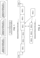
- figure 2 shows a production line that consists of a number of six modular units connected to each other in succession. They are part of the modules of the standard group of the example indicated in figure 1 and therefore there are in succession:
- a modular unit 1 which is followed by two modular units 2 which are followed by a further modular unit 1 and which is followed by two further modular units 3.
- the figure then schematically shows a manufacturing inlet to the line and an outlet of the finished sanitary product.
- the modular units are standard, that is, a certain type of models constituting a group being defined, the lines are realized by combining together the only models of the group according to the needs. Each unit is therefore compatible with all the others in the group in terms of connections and to determine a continuity.
- the unit 1 of the first line can be inserted in place of the unit 2 of the second line should this be necessary, just as a new unit 3 can replace a unit 1 or a unit 2 of the first and second line, respectively.
- the modular units are all compatible with each other and it is possible to add and/or remove and/or replace a unit from/in a line according to the needs.
- the design is also simple as the modules (or units as it may be) realized will always be the same relative to the group and then, by combining the modules together, it will be possible to realize lines of any length and for any need with great flexibility and versatility of the line itself.
- Each module will therefore have a structural support frame that belongs to a standardized group, making it possible to achieve the flexibility and interchangeability described above.
- Each frame can therefore have geometric characteristics that are different from module to module while still having mutually compatible connection parts that ensure that several modules can be freely arranged in succession according to the needs.
- the units described herein comprise the structural support frame (also simply called support frame or frame) which is as said standard.
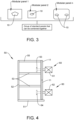
- figure 4 shows a modular manufacturing unit 50 having a rest base 51 on which the structural support frame (52, 53, 54) raises.
- Said support frame may provide one or more rear vertical bars 52 and one or more front vertical bars 54, preferably arranged substantially parallel to each other.
- Said bars raise orthogonally from the base 51.
- an upper closure 55 may be provided which may also be a single beam or a combination of beams and/or a panel.
- this frame may vary from module to module but are included in a standardized group.
- the front face 54 of the units conforms the front face of the line and the rear face 52 of the unit (relative to the trusses 52) conforms the rear face of the line.
- An operative assembly is therefore the set of the panel 11 to which one or more operative apparatuses 60 are fixed in a removable way.
- an operative apparatus 60 formed by an operative part (61, 62) and a motorization part (63, 64) is connected to a panel 11.
- the motorization part is the one indicated with numberings 63 and 64 and are placed inside the structure of the unit whereas externally there is the operative part performing the manufacturing and indicated in figure 4 with numberings 61 and 62.
- these operative apparatuses are connected in a removable way such that there is an operative part (61, 62) that stretches from one face of the panel and a motorization part that, on the opposite part, extends from the other opposite face.
- the panels are arranged so that the operative apparatuses can be fixed thereto and, as for example schematized in figure 3 , special passage holes 10 of different conformation can be provided depending on the operative apparatus to be connected.
- the connection can be completed with appropriate connection means such as screws, bolts, etc.
- the panel can then, in turn, be easily connected to the frame in a removable way, for example always through connection means such as screws, bolts, etc.
- the panels can advantageously be standard and therefore can be part of a group of standard panels that can be combined and compatible between them with all the modular units introduced above.
- these panels are predefined models with conformations different from each other within the group.
- figure 3 shows, in a non-limiting way, three panels (three models that make up the predefined group) that are geometrically different from each other.
- an operative assembly can be replaced with an equivalent one already ready, for example in the event of a failure or after upgrading the line, for example by replacing this operative assembly with one already ready and compatible but of different configuration, for example mounting different motors and/or different apparatuses.
- each modular unit is realized as said in such a way as to be combinable with the other units of the group generating a continuity, albeit with a different configuration.
- this allows at least one cleaning robot 110 to be applied, which can for example move continuously along a track formed by the units combined together, and this guide track continues to be present even when a unit is replaced with one having a different configuration. All this because the units, as said, are standard and therefore are predefined models belonging to a group of models compatible with each other.
- the robot 110 can be equipped with cameras and can possibly be driven remotely, as well as it could be programmed to be autonomous and automatic.
- It has a cleaning end that acts to clean for example by suction and/or by spraying suitable substances.
- the robot 110 moves within a corridor 100 from the front part 54, which part is delimited by the protections (Ps1....Psn).
- protections are in the form of panellings or panels in general, for example of plastic and/or transparent material to allow seeing inside.
- the protective panels are mounted in a slidable manner so that they can be packed together.
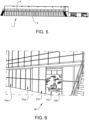
- Figure 5 which shows the entire line in front view, shows how these panels extend forming a protective barrier along the entire longitudinal length of the manufacturing line and, as can be seen from figure 6 , spaced from the front part 54 of the line in such a way as to form a corridor of easy access for the operator.
- a special support frame shown in the dotted line figures, allows the panels to be supported and have them slide as described, for example the same structural support frame of the module.
- figure 7 shows the production line in top view.
- the electrical control panels are now arranged on the ground from the rear part 52 of the production line (i.e. from the part towards which the motors 63, 64 extend, for example, with reference to figure 4 ) and the raceways or platforms 140 covering the electrical cables are highlighted. In this way, a further passage corridor 130 delimited by the electrical panels 120 and the rear face 52 is formed.
- a production line for absorbent products for sanitary use can be obtained by combining together the units belonging to a specific group, therefore by combining together only the designed and realized standard units.
- the panels can possibly (not necessarily) be standard, and therefore they also belong to a predefined standard group, thus being compatible with said standard units.
Landscapes
- Health & Medical Sciences (AREA)
- Life Sciences & Earth Sciences (AREA)
- Engineering & Computer Science (AREA)
- Vascular Medicine (AREA)
- Manufacturing & Machinery (AREA)
- Epidemiology (AREA)
- Biomedical Technology (AREA)
- Heart & Thoracic Surgery (AREA)
- Botany (AREA)
- Animal Behavior & Ethology (AREA)
- General Health & Medical Sciences (AREA)
- Public Health (AREA)
- Veterinary Medicine (AREA)
- Automatic Assembly (AREA)
- Absorbent Articles And Supports Therefor (AREA)
- Multi-Process Working Machines And Systems (AREA)
Applications Claiming Priority (1)
| Application Number | Priority Date | Filing Date | Title |
|---|---|---|---|
| IT202300026757 | 2023-12-15 |
Publications (1)
| Publication Number | Publication Date |
|---|---|
| EP4570221A1 true EP4570221A1 (de) | 2025-06-18 |
Family
ID=90057567
Family Applications (1)
| Application Number | Title | Priority Date | Filing Date |
|---|---|---|---|
| EP24202224.2A Pending EP4570221A1 (de) | 2023-12-15 | 2024-09-24 | Produktionslinie zur herstellung von sanitärprodukten wie absorbierenden produkten für den sanitärgebrauch |
Country Status (2)
| Country | Link |
|---|---|
| EP (1) | EP4570221A1 (de) |
| JP (1) | JP2025096146A (de) |
Citations (3)
| Publication number | Priority date | Publication date | Assignee | Title |
|---|---|---|---|---|
| US20130014902A1 (en) * | 2010-03-19 | 2013-01-17 | Unicharm Corporation | Absorbent article manufacturing device |
| US20150173965A1 (en) * | 2013-12-20 | 2015-06-25 | The Procter & Gamble Company | Modular unit operations for a flexible mount converter |
| US20150176750A1 (en) * | 2013-12-20 | 2015-06-25 | The Procter & Gamble Company | Base for a flexible mount converter |
Family Cites Families (1)
| Publication number | Priority date | Publication date | Assignee | Title |
|---|---|---|---|---|
| US5383988A (en) * | 1992-09-10 | 1995-01-24 | Paragon Trade Brands, Inc. | Modular apparatus for fabricating an absorbent article |
-
2024
- 2024-09-24 EP EP24202224.2A patent/EP4570221A1/de active Pending
- 2024-10-04 JP JP2024175051A patent/JP2025096146A/ja active Pending
Patent Citations (3)
| Publication number | Priority date | Publication date | Assignee | Title |
|---|---|---|---|---|
| US20130014902A1 (en) * | 2010-03-19 | 2013-01-17 | Unicharm Corporation | Absorbent article manufacturing device |
| US20150173965A1 (en) * | 2013-12-20 | 2015-06-25 | The Procter & Gamble Company | Modular unit operations for a flexible mount converter |
| US20150176750A1 (en) * | 2013-12-20 | 2015-06-25 | The Procter & Gamble Company | Base for a flexible mount converter |
Also Published As
| Publication number | Publication date |
|---|---|
| JP2025096146A (ja) | 2025-06-26 |
Similar Documents
| Publication | Publication Date | Title |
|---|---|---|
| JP2020097226A (ja) | 連続するループ状の積層経路に沿って複合積層材を積層するためのシステム及び方法 | |
| EP2744711B1 (de) | System zum bewegen von bedieneinheiten für eine verpackungsmaschine und verpackungsmaschine | |
| KR19980018481A (ko) | 열교환기의 열교환용 튜브 조립장치 및 조립방법 | |
| US20120205048A1 (en) | Wind turbine blade automated production system | |
| WO2007120438A2 (en) | Modular robotic work cell | |
| DE102010009536A1 (de) | Verfahren zum Wechsel des Ober- und Unterwerkzeugs einer Verpackungsmaschine | |
| EP4570221A1 (de) | Produktionslinie zur herstellung von sanitärprodukten wie absorbierenden produkten für den sanitärgebrauch | |
| ITMO20070141A1 (it) | Apparati di protezione | |
| US20120227242A1 (en) | Method and injection molding machine having a modular structure | |
| IT201800004759A1 (it) | Linea di assemblaggio di sottoinsiemi di carrozzeria di autoveicoli | |
| EP3053838B1 (de) | Modulare vorrichtung zum verpacken von zigaretten oder zigaretten- packungen | |
| US20200282443A1 (en) | Punch press set-up | |
| RU2637679C2 (ru) | Способ изготовления роторной лопасти | |
| JP5421172B2 (ja) | 溶接ライン | |
| ITSV980033A1 (it) | Macchina operatrice modulare. | |
| WO2018041972A1 (de) | Behälter-wechselvorrichtung | |
| EP3754444B1 (de) | Verfahren zum wechseln eines aggregates an einer verpackungsstrasse sowie hierfür ausgelegte verpackungsstrasse | |
| CN212371484U (zh) | 一种施工电梯附墙架的自动焊接设备 | |
| EP3492195A1 (de) | Maschine zur herstellung von sandformen | |
| KR20100057130A (ko) | 모듈화된 팰릿 반송 및 저장 시스템 | |
| CN113042871B (zh) | 中顶蒙皮机器人自动点焊工作站 | |
| RU2487004C2 (ru) | Способ многоярусного компонования и перекомпонования рабочей позиции автоматической линии и перекомпонуемая рабочая позиция автоматической линии для реализации способа | |
| ITBO990458A1 (it) | Apparecchiatura per la realizzazione di cornici rettangolari . | |
| CN112299096B (zh) | 用于卷带材料的开卷机 | |
| CN114193774A (zh) | 一种高效防护口罩生产工艺 |
Legal Events
| Date | Code | Title | Description |
|---|---|---|---|
| PUAI | Public reference made under article 153(3) epc to a published international application that has entered the european phase |
Free format text: ORIGINAL CODE: 0009012 |
|
| STAA | Information on the status of an ep patent application or granted ep patent |
Free format text: STATUS: THE APPLICATION HAS BEEN PUBLISHED |
|
| AK | Designated contracting states |
Kind code of ref document: A1 Designated state(s): AL AT BE BG CH CY CZ DE DK EE ES FI FR GB GR HR HU IE IS IT LI LT LU LV MC ME MK MT NL NO PL PT RO RS SE SI SK SM TR |
|
| STAA | Information on the status of an ep patent application or granted ep patent |
Free format text: STATUS: REQUEST FOR EXAMINATION WAS MADE |
|
| STAA | Information on the status of an ep patent application or granted ep patent |
Free format text: STATUS: EXAMINATION IS IN PROGRESS |
|
| 17P | Request for examination filed |
Effective date: 20250909 |
|
| 17Q | First examination report despatched |
Effective date: 20250924 |
|
| GRAP | Despatch of communication of intention to grant a patent |
Free format text: ORIGINAL CODE: EPIDOSNIGR1 |
|
| STAA | Information on the status of an ep patent application or granted ep patent |
Free format text: STATUS: GRANT OF PATENT IS INTENDED |
|
| INTG | Intention to grant announced |
Effective date: 20251103 |