EP4570098A2 - Aerosolerzeugungsvorrichtung und verfahren zur steuerung davon - Google Patents
Aerosolerzeugungsvorrichtung und verfahren zur steuerung davon Download PDFInfo
- Publication number
- EP4570098A2 EP4570098A2 EP25174030.4A EP25174030A EP4570098A2 EP 4570098 A2 EP4570098 A2 EP 4570098A2 EP 25174030 A EP25174030 A EP 25174030A EP 4570098 A2 EP4570098 A2 EP 4570098A2
- Authority
- EP
- European Patent Office
- Prior art keywords
- heater
- aerosol generating
- temperature
- preheating completion
- holder
- Prior art date
- Legal status (The legal status is an assumption and is not a legal conclusion. Google has not performed a legal analysis and makes no representation as to the accuracy of the status listed.)
- Pending
Links
Images





Classifications
-
- A—HUMAN NECESSITIES
- A24—TOBACCO; CIGARS; CIGARETTES; SIMULATED SMOKING DEVICES; SMOKERS' REQUISITES
- A24F—SMOKERS' REQUISITES; MATCH BOXES; SIMULATED SMOKING DEVICES
- A24F40/00—Electrically operated smoking devices; Component parts thereof; Manufacture thereof; Maintenance or testing thereof; Charging means specially adapted therefor
- A24F40/50—Control or monitoring
-
- A—HUMAN NECESSITIES
- A24—TOBACCO; CIGARS; CIGARETTES; SIMULATED SMOKING DEVICES; SMOKERS' REQUISITES
- A24F—SMOKERS' REQUISITES; MATCH BOXES; SIMULATED SMOKING DEVICES
- A24F40/00—Electrically operated smoking devices; Component parts thereof; Manufacture thereof; Maintenance or testing thereof; Charging means specially adapted therefor
- A24F40/20—Devices using solid inhalable precursors
-
- A—HUMAN NECESSITIES
- A24—TOBACCO; CIGARS; CIGARETTES; SIMULATED SMOKING DEVICES; SMOKERS' REQUISITES
- A24F—SMOKERS' REQUISITES; MATCH BOXES; SIMULATED SMOKING DEVICES
- A24F40/00—Electrically operated smoking devices; Component parts thereof; Manufacture thereof; Maintenance or testing thereof; Charging means specially adapted therefor
- A24F40/50—Control or monitoring
- A24F40/53—Monitoring, e.g. fault detection
-
- A—HUMAN NECESSITIES
- A24—TOBACCO; CIGARS; CIGARETTES; SIMULATED SMOKING DEVICES; SMOKERS' REQUISITES
- A24F—SMOKERS' REQUISITES; MATCH BOXES; SIMULATED SMOKING DEVICES
- A24F40/00—Electrically operated smoking devices; Component parts thereof; Manufacture thereof; Maintenance or testing thereof; Charging means specially adapted therefor
- A24F40/50—Control or monitoring
- A24F40/57—Temperature control
-
- G—PHYSICS
- G05—CONTROLLING; REGULATING
- G05D—SYSTEMS FOR CONTROLLING OR REGULATING NON-ELECTRIC VARIABLES
- G05D23/00—Control of temperature
- G05D23/19—Control of temperature characterised by the use of electric means
- G05D23/1917—Control of temperature characterised by the use of electric means using digital means
-
- H—ELECTRICITY
- H05—ELECTRIC TECHNIQUES NOT OTHERWISE PROVIDED FOR
- H05B—ELECTRIC HEATING; ELECTRIC LIGHT SOURCES NOT OTHERWISE PROVIDED FOR; CIRCUIT ARRANGEMENTS FOR ELECTRIC LIGHT SOURCES, IN GENERAL
- H05B1/00—Details of electric heating devices
- H05B1/02—Automatic switching arrangements specially adapted to apparatus ; Control of heating devices
-
- H—ELECTRICITY
- H05—ELECTRIC TECHNIQUES NOT OTHERWISE PROVIDED FOR
- H05B—ELECTRIC HEATING; ELECTRIC LIGHT SOURCES NOT OTHERWISE PROVIDED FOR; CIRCUIT ARRANGEMENTS FOR ELECTRIC LIGHT SOURCES, IN GENERAL
- H05B1/00—Details of electric heating devices
- H05B1/02—Automatic switching arrangements specially adapted to apparatus ; Control of heating devices
- H05B1/0227—Applications
- H05B1/023—Industrial applications
- H05B1/0244—Heating of fluids
-
- H—ELECTRICITY
- H02—GENERATION; CONVERSION OR DISTRIBUTION OF ELECTRIC POWER
- H02J—ELECTRIC POWER NETWORKS; CIRCUIT ARRANGEMENTS OR SYSTEMS FOR SUPPLYING OR DISTRIBUTING ELECTRIC POWER; SYSTEMS FOR STORING ELECTRIC ENERGY
- H02J7/00—Circuit arrangements for charging or discharging batteries or for supplying loads from batteries
- H02J7/855—Circuit arrangements for charging or discharging batteries or for supplying loads from batteries with circuits adapted for supplying loads from the battery
Definitions
- One or more embodiments of the present disclosure relate to an aerosol generating device and a method of controlling the same.
- the cigarette When using an aerosol generating device including a heater that heats a cigarette by using electricity, the cigarette needs to be adequately preheated by the heater in order to generate an adequate amount of aerosol from the aerosol generating material in the cigarette.
- the cigarette may not be adequately preheated by the heater. Therefore, there is a need for a technique for regulating a preheating parameter by considering the initial temperature of the heater.
- One or more embodiments of the present disclosure provide an aerosol generating device and a method of controlling the same.
- the aerosol generating device according to the present embodiment may set a preheating completion parameter, based on an initial temperature of a heater. By preheating a cigarette according to the set preheating completion parameter, the aerosol generating device may supply heat to an aerosol generating material in the cigarette, such that an adequate amount of aerosol is generated even when the initial temperature of the heater changes.
- the aerosol generating device may measure a current temperature of a heater before power is supplied to the heater that heats an aerosol generating material, and may set a preheating completion parameter, based on the measured current temperature of the heater, and a value of an amount of heat required to be supplied to the aerosol generating material to generate an adequate amount of aerosol. Based on the preheating completion parameter, the aerosol generating device may control power supplied to the heater, such that a value of an amount of heat supplied to the aerosol generating material by the heater reaches the value of the required amount of heat.
- the aerosol generating device may set a preheating completion parameter, based on an initial temperature of a heater, such that an adequate amount of aerosol is generated from an aerosol generating material at the time of the completion of preheating. Even when the initial temperature of the heater is high, the aerosol generating device according to the present disclosure may supply an adequate amount of heat to the aerosol generating material until the preheating is completed, by increasing a preheating completion temperature of the heater or extending a preheating completion time.
- a method of controlling an aerosol generating device includes: measuring a current temperature of a heater before power is supplied to the heater that heats an aerosol generating material; setting a preheating completion parameter, based on the measured current temperature of the heater, and a value of an amount of heat required to be supplied to the aerosol generating material to generate an adequate amount of aerosol; and controlling power supplied to the heater, based on the preheating completion parameter, such that a value of an amount of heat supplied to the aerosol generating material by the heater reaches the value of the required amount of heat.
- an aerosol generating device includes: a heater configured to heat an aerosol generating material; a battery configured to supply power to the heater; and a controller, wherein the controller measures a current temperature of the heater before power is supplied to the heater, sets a preheating completion parameter, based on the measured current temperature of the heater, and a value of an amount of heat required to be supplied to the aerosol generating material to generate an adequate amount of aerosol, and controls power supply from the battery to the heater, based on the preheating completion parameter such that a value of an amount of heat supplied to the aerosol generating material by the heater reaches the value of the required amount of heat.
- a computer- readable recording medium has recorded thereon a computer program for executing the method according to the one aspect of the present disclosure.
- FIG. 1 is a block diagram showing an example of an aerosol generating device.
- an aerosol generating device 1 (hereinafter, referred to as a 'holder') includes a battery 110, a controller 120, and a heater 130.
- the holder 1 also includes an inner space formed by a case 140. A cigarette may be inserted into the inner space of the holder 1.
- the holder 1 heats the heater 130.
- the temperature of an aerosol generating material in the cigarette is increased by the heated heater 130, thereby generating an aerosol.
- the generated aerosol is delivered to a user through a filter of the cigarette. Still, even when the cigarette is not inserted into the holder 1, the holder 1 may heat the heater 130, for example, to clean the heater 130.
- the case 140 may be moved between a first position and a second position. For example, when the case 140 is in the first position, the user may insert the cigarette into the holder 1 to inhale the aerosol. On the other hand, when the case 140 is in the second position, the user may remove (separate) the cigarette from the holder 1. As the user pushes or pulls the case 140, the case 140 may be moved between the first position and the second position. In addition, the case 140 may be completely separated from the holder 1 by the user's manipulation.
- the diameter of a hole formed by an end 141 of the case 140 may be made smaller than the diameter of a space formed by the case 140 and the heater 130, and in that case, the hole may serve as a guide for the cigarette inserted into the holder 1.
- the battery 110 supplies power used for the holder 1 to operate.
- the battery 110 may supply power for the heater 130 to be able to be heated, and may supply power required for the controller 120 to operate.
- the battery 110 may supply power required for a display, sensor, motor, and the like installed in the holder 1 to operate.
- the battery 110 may be a lithium iron phosphate (LiFePO4) battery.
- LiFePO4 lithium iron phosphate
- the battery 110 may be a lithium cobalt oxide (LiCoO2) battery, a lithium titanate battery, or the like.
- Whether the battery 110 is fully charged or completely discharged may be determined based on a level of power stored in the battery 110 compared to the total capacity of the battery 110. For example, when the power stored in the battery 110 is 95% or more of the total capacity of the battery 110, it may be determined that the battery 110 is fully charged. In addition, when the power stored in the battery 110 is 10% or less of the total capacity of the battery 110, it may be determined that the battery 110 is completely discharged.
- the criteria for determining whether the battery 110 is fully charged or completely discharged is not limited to the above-described example.
- the heater 130 is heated by power supplied by the battery 110.
- the heater 130 is located inside the cigarette. Therefore, the heated heater 130 may increase the temperature of the aerosol generating material in the cigarette.
- the heater 130 may be manufactured in a shape in which the heater 130 may be easily inserted into the cigarette.
- the heater 130 may have a blade form or a shape in which a cylinder and a cone are combined to each other.
- embodiments of the present disclosure are not limited thereto.
- only a portion of the heater 130 may be heated.
- only a first portion of the heater 130 may be heated and a second portion of the heater 130 may not be heated.
- the first portion may be a portion in which a cigarette rod is located when the cigarette is inserted into the holder 1.
- the heater 130 may be heated to a different temperature for each portion.
- the above-described first and second portions may be heated to different temperatures.
- the heater 130 may be an electric resistive heater.
- the heater 130 may be manufactured such that an electrically conductive track is disposed on a substrate formed of an electrically insulating material.
- the substrate may be made of a ceramic material, and the electrically conductive track may be made of tungsten.
- embodiments of the present disclosure are not limited thereto.
- a separate temperature detection sensor may be provided in the holder 1.
- the holder 1 may not be provided with a temperature detection sensor, and the heater 130 may serve as a temperature detection sensor.
- the heater 130 of the holder 1 serves as a temperature detection sensor
- a separate temperature detection sensor may be further provided in the holder 1.
- the heater 130 may include at least one electrically conductive track to detect heat generation or temperature.
- the heater 130 may separately include a second electrically conductive track to detect temperature in addition to a first electrically conductive track to detect heat generation.
- resistance R may be determined when a voltage applied to the electrically conductive track and a current flowing through the electrically conductive track are measured.
- temperature T of the electrically conductive track may be determined by Equation 1 below.
- R R c 1 ⁇ ⁇ T ⁇ T c
- Equation 1 R refers to a current resistance value of the electrically conductive track
- R 0 refers to a resistance value at temperature T 0 (e.g., 0 °C)
- ⁇ refers to a resistance temperature coefficient of the electrically conductive track. Since a conductive material (e.g., metal) has an intrinsic resistance temperature coefficient, ⁇ may be predetermined depending on the conductive material constituting the electrically conductive track. Therefore, when the resistance R of the electrically conductive track is determined, the temperature T of the electrically conductive track may be calculated by Equation 1 above.
- the electrically conductive track includes an electrically resistive material.
- the electrically conductive track may be made of a metallic material.
- the electrically conductive track may be made of an electrically conductive ceramic material, carbon, a metal alloy, or a composite material of a ceramic material and a metal.
- the holder 1 may include both the electrically conductive track that serves as a temperature detection sensor, and the temperature detection sensor.
- the controller 120 controls the overall operation of the holder 1. More specifically, the controller 120 controls the operation of not only the battery 110 and the heater 130, but also other components included in the holder 1. In addition, the controller 120 may check states of each of the components of the holder 1 to determine whether or not the holder 1 is in an operable state.
- the controller 120 includes at least one processor.
- the processor may be implemented as an array of a plurality of logic gates, or may be implemented as a combination of a general-purpose microprocessor and a memory in which a program executable in the microprocessor is stored.
- the processor may be implemented with other types of hardware.
- the controller 120 may control the operation of the heater 130.
- the controller 120 may control an amount of power supplied to the heater 130 and a time at which power is supplied to the heater 130 such that the heater 130 is heated to a certain temperature or maintains an appropriate temperature.
- the controller 120 may check the state of the battery 110 (e.g., remaining capacity of the battery 110, etc.) and generate a notification signal, if necessary.
- the controller 120 may also check the presence or absence of a puff of the user and the intensity of the puff, and may count the number of puffs. Moreover, the controller 120 may continue to check a time during which the holder 1 is operating. The controller 120 may also check whether or not a cradle 2 to be described later is coupled to the holder 1, and may control the operation of the holder 1 depending on the coupling or separation of the cradle 2 and the holder 1.
- the holder 1 may further include general-purpose components in addition to the battery 110, the controller 120, and the heater 130.
- the holder 1 may include a display capable of outputting visual information, or a motor to output tactile information.
- the controller 120 may transmit, to the user through the display, information on a state of the holder 1 (for example, availability of the holder 1, etc.), information on the heater 13 (for example, start of preheating, progress of preheating, completion of preheating, etc.), information related to the battery 110 (for example, remaining capacity of the battery 110, availability of the battery 110, etc.), information related to resetting of the holder 1 (for example, timing for resetting, progress of resetting, completion of resetting, etc.), information related to cleaning of the holder 1 (for example, timing for cleaning, need of cleaning, progress of cleaning, completion of cleaning, etc.), information related to charging of the holder 1 (for example, need of charging, progress of charging, completion of charging, etc.), information related to puffs (for example, the number of puffs, notice of puff termination, etc.), information related to
- the holder 1 may include at least one input device (e.g., a button) through which the user may control the function of the holder 1 and/or a terminal coupled to the cradle 2.
- the user may use the input device of the holder 1 to execute various functions.
- the user may regulate the number of times (e.g., once, twice, etc.) for which the user presses the input device, or a time (e.g., 0.1 seconds, 0.2 seconds, etc.) during which the user presses the input device to execute the desired function of multiple functions of the holder 1.
- the holder 1 may perform a function of preheating the heater 130, a function of regulating the temperature of the heater 130, a function of cleaning the space into which the cigarette is inserted, a function of checking whether or not the holder 1 is in an operable state, a function of displaying the remaining capacity (available power) of the battery 110, a function of resetting the holder 1, and the like.
- functions of the holder 1 are not limited thereto.
- the holder 1 may clean the space into which the cigarette is inserted by controlling the heater 130 as follows.
- the holder 1 may heat the heater 130 to a temperature high enough to clean the space into which the cigarette is inserted.
- the temperature high enough refers to a temperature suitable for cleaning the space into which the cigarette is inserted.
- the holder 1 may heat the heater 130 to the highest temperature among a temperature range within which an aerosol may be generated from the inserted cigarette and a temperature range within which the heater 130 is preheated.
- embodiments of the present disclosure are not limited thereto.
- the holder 1 may maintain the temperature of the heater 130 at a temperature high enough for a certain period of time.
- the certain period of time refers to a time period sufficient for the space into which the cigarette is inserted to be cleaned.
- the holder 1 may maintain the temperature of the heater 130 heated for an appropriate time period of 10 seconds to 10 minutes.
- embodiments of the present disclosure are not limited thereto.
- holder 1 may maintain the temperature of the heater 130 heated for an appropriate time period selected from within a range of 20 seconds to 1 minute.
- the holder 1 may maintain the temperature of the heater 130 heated for an appropriate time period selected from within a range of 20 seconds to 1 minute and 30 seconds.
- the holder 1 heats the heater 130 to a temperature high enough and maintains the temperature of the heater 130 heated for a certain time period, material deposited on a surface of the heater 130 and/or in the space into which the cigarette is inserted is volatilized, thereby cleaning the holder 1.
- the holder 1 may also include a puff detection sensor, a temperature detection sensor and/or a cigarette insertion detection sensor.
- the puff detection sensor may be implemented by a general pressure sensor.
- the holder 1 may detect a puff through a change in the resistance of the electrically conductive track included in the heater 130 without including a separate puff detection sensor.
- the electrically conductive track includes an electrically conductive track for heat generation and/or an electrically conductive track for temperature detection.
- the holder 1 may further include a puff detection sensor separately from detecting a puff by using the electrically conductive track included in the heater 130.
- the cigarette insertion detection sensor may be implemented by a general capacitive sensor or a resistance sensor.
- the holder 1 may be manufactured in a structure in which air may flow in from the outside and flow out even when the cigarette is inserted.
- FIG. 2 is a diagram showing an example of a holder.
- the holder 1 may be manufactured in a cylindrical shape. However, embodiments of the present disclosure are not limited thereto.
- the case 140 of the holder 1 may be moved or separated by a user's motion, and a cigarette may be inserted into the end 141 of the case 140.
- the holder 1 may include a button 150 through which the user is able to control the holder 1. If necessary, the holder 1 may further include a display on which an image is output.
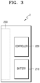
- FIG. 3 is a block diagram showing an example of a cradle.
- the cradle 2 includes a battery 210 and a controller 220.
- the cradle 2 also includes an inner space 230 into which the holder 1 may be inserted.
- the cradle 2 may or may not include a separate lid.
- the holder 1 may be inserted into and fixed to the cradle 2.
- the lid of the cradle 2 is closed after the holder 1 is inserted into the cradle 2, the holder 1 may be fixed to the cradle 2.
- the battery 210 supplies power used for the cradle 2 to operate.
- the battery 210 may also supply power for the battery 110 of the holder 1 to be charged.
- the battery 210 of the cradle 2 may supply power to the battery 110 of the holder 1.
- the battery 210 may supply power used for the holder 1 to operate.
- the holder 1 may use power supplied by the battery 210 of the cradle 2 to operate.
- the battery 210 may be a lithium ion battery. However, embodiments of the present disclosure are not limited thereto. In addition, the capacity of the battery 210 may be greater than that of the battery 110.
- the controller 220 controls the overall operation of the cradle 2.
- the controller 220 may control the operation of all components of the cradle 2.
- the controller 220 may determine whether the holder 1 and the cradle 2 are coupled to each other, and may control the operation of the cradle 2 depending on the coupling or separation of the cradle 2 and the holder 1.
- the controller 220 may supply power of the battery 210 to the holder 1 to charge the battery 110 or heat the heater 130. Therefore, even when the remaining capacity of the battery 110 is small, a user may continue to smoke by coupling the holder 1 to the cradle 2
- the controller 220 may include at least one processor.
- the processor may be implemented as an array of a plurality of logic gates, or may be implemented as a combination of a general-purpose microprocessor and a memory in which a program executable in the microprocessor is stored.
- the processor may be implemented with other types of hardware.
- the cradle 2 may further include general-purpose components in addition to the battery 210 and the controller 220.
- the cradle 2 may include a display capable of outputting visual information.
- the controller 220 may generate a signal to be displayed on the display to provide the user with information related to the battery 210 (e.g., remaining capacity, availability, and the like of the battery 210), information related to reset of the cradle 2 (e.g., a time for resetting, progress of resetting, completion of resetting, and the like), information related to cleaning of the holder 1 (e.g., cleaning timing, need of cleaning, cleaning progress, cleaning completion, and the like), information related to charging of the cradle 2 (e.g., need of charging, charging progress, charging completion, and the like), and the like.
- the cradle 2 may include at least one input device (for example, a button) through which the user is able to control the function of the cradle 2, a terminal coupled to the holder 1, and/or an interface (for example, USB port, etc.) to charge the battery 210.
- a button for example, a button
- an interface for example, USB port, etc.
- the user may execute various functions by using the input device of the cradle 2.
- the user may regulate the number of times for which the user presses the input device or a time during which the user presses the input device to execute the desired function of multiple functions of the cradle 2.
- the cradle 2 may perform a function of preheating the heater 130, a function of regulating the temperature of the heater 130, a function of cleaning the space into which the cigarette is inserted, a function of checking whether or not the cradle 2 is in an operable state, a function of displaying the remaining capacity (available power) of the battery 210, a function of resetting the cradle 2, and the like.
- functions of the cradle 2 are not limited thereto.
- FIGS. 4A and 4B are diagrams showing examples of a cradle.
- FIG. 4A shows an example of the cradle 2 not including a lid.
- the space 230 into which the holder 1 may be inserted may be present on one side of the cradle 2. Even when the cradle 2 does not include a separate fixing means such as a lid, the holder 1 may be inserted into and fixed to the cradle 2.
- the cradle 2 may include a button 240 through which a user is able to control the cradle 2.
- the cradle 2 may further include a display on which an image is output, if necessary.
- FIG. 4B shows an example of the cradle 2 including a lid.
- the holder 1 may be fixed to the cradle 2.
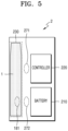
- FIG. 5 is a diagram showing an example in which a holder is inserted into a cradle.
- FIG. 5 shows an example in which the holder 1 is inserted into the cradle 2. Since the space 230 into which the holder 1 is to be inserted is present on one side of the cradle 2, the inserted holder 1 may not be exposed to the outside by other sides of the cradle 2. Therefore, the cradle 2 may not include other components (e.g., a lid) to not expose the holder 1 to the outside.
- the cradle 2 may not include other components (e.g., a lid) to not expose the holder 1 to the outside.
- the cradle 2 may include at least one coupling member 271 or 272 to increase coupling intensity with the holder 1.
- the holder 1 may include at least one coupling member 181.
- the coupling members 181, 271, and 272 may correspond to magnets.
- embodiments of the present disclosure are not limited thereto. For convenience of description, it is shown that the holder 1 includes one coupling member 181 and the cradle 2 includes two coupling members 271 and 272 in FIG. 5 , but the number of coupling members 181, 271, and 272 is not limited thereto.
- the holder 1 may include the coupling member 181 in a first position, and the cradle 2 may include coupling members 271 and 272 in a second position and a third position, respectively. In that case, the first position and the third position may face each other when the holder 1 is inserted into the cradle 2.
- the holder 1 and the cradle 2 include the coupling members 181, 271, and 272, even when the holder 1 is inserted into one side of the cradle 2, the holder 1 and the cradle 2 may be coupled to each other more firmly than before.
- the holder 1 and the cradle 2 further include the coupling members 181, 271, and 272 in addition to terminals, the holder 1 and the cradle 2 may be coupled to each other more firmly than before. Therefore, even when the cradle 2 does not include a separate component (e.g., a lid), the inserted holder 1 may not be easily separated from the cradle 2.
- a separate component e.g., a lid
- the controller 220 may use power of the battery 210 to charge the battery 110 of the holder 1.
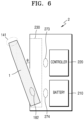
- FIG. 6 is a diagram showing an example in which a holder is tilted while being inserted into a cradle.
- FIG. 6 shows that the holder 1 is tilted inside the cradle 2.
- tilt refers to that the holder 1 is inclined at a certain angle while being inserted into the cradle 2.
- the end 141 of the holder 1 is exposed to the outside.
- the user may insert the cigarette into the end 141 and inhale (smoke) a generated aerosol.
- a tilt angle ⁇ may be adequately angled, such that the cigarette is not bent or damaged.
- the holder 1 may be tilted at a minimum angle at which an entire cigarette insertion hole included in the end 141 is exposed to the outside or an angle larger than that.
- the range of the tilt angle ⁇ may be more than 0 ° and 180 ° or less, and it is desirable that the range of the tilt angle ⁇ be 5 ° or more and 90 ° or less. It is more desirable that the range of the tilt angle ⁇ be 5 ° or more and 20 ° or less, 5 ° or more and 30 ° or less, 5 ° or more and 40 ° or less, 5 ° or more and 50 ° or less, or 5 ° or more and 60 ° or less. It is most desirable that the tilt angle ⁇ be 10 °.
- the heater 130 of the holder 1 may be heated by power supplied by the battery 210 of the cradle 2. Therefore, even when the remaining capacity of the battery 110 of the holder 1 is small or none, the holder 1 may use the battery 210 of the cradle 2 to generate an aerosol.
- FIG. 6 shows an example in which the holder 1 includes one coupling member 182 and the cradle 2 includes two coupling members 273 and 274.
- positions of each of the coupling members 182, 273, and 274 are as described above with reference to FIG. 5 .
- the coupling members 182, 273, and 274 are magnets
- magnet intensity of the coupling member 274 may be greater than that of the coupling member 273. Therefore, even when the holder 1 is tilted, the holder 1 may not be completely separated from the cradle 2 thanks to the coupling members 182 and 274.
- the controller 220 may use power of the battery 210 to heat the heater 130 of the holder 1 or charge the battery 110.
- FIG. 7 is a flowchart of a method of controlling an aerosol generating device, according to an embodiment.
- the aerosol generating device may measure a current temperature of a heater before power is supplied to the heater that heats an aerosol generating material.
- the aerosol generating device may measure the current temperature of the heater before power is supplied from a battery to the heater by using a temperature detection sensor.
- the aerosol generating device may be provided with a separate temperature detection sensor.
- the aerosol generating device may not be provided with a temperature detection sensor, and the heater may serve as a temperature detection sensor.
- the aerosol generating device may be further provided with a separate temperature detection sensor while the heater serves as a temperature detection sensor.
- the heater may include at least one electrically conductive track for heat generation or temperature detection.
- the heater may separately include a second electrically conductive track for temperature detection in addition to a first electrically conductive track for heat generation.
- the current temperature of the heater Before power is supplied to the heater, the current temperature of the heater may be different from time to time.
- the temperature of the heater in the aerosol generating device placed at room temperature for a certain period of time may maintain room temperature.
- the current temperature of the heater may be maintained at a temperature higher than room temperature in various situations, such as when the aerosol generating device is left in a vehicle for a certain period of time or more in summer, or continuous smoking is performed using the aerosol generating device.
- a preheating completion temperature for preheating a cigarette may be set in anticipation of a case where an initial temperature of the heater is a specific temperature (e.g., room temperature).
- a specific temperature e.g., room temperature.
- a time required for the temperature of the heater to reach the preheating completion temperature may be shortened. That is, in order for the aerosol generating material to be heated by the heater to generate an adequate amount of aerosol, an amount of heat to be supplied to the aerosol generating material needs to be at least a certain amount.
- the aerosol generating device may set a preheating completion parameter based on the measured current temperature of the heater, and a value of an amount of heat required to be supplied to the aerosol generating material to generate an adequate amount of aerosol.
- the aerosol generating device may set the preheating completion parameter, based on the current temperature of the heater, and may supply the required amount of heat to the aerosol generating material, based on the preheating completion parameter set to generate an adequate amount of aerosol.
- the aerosol generating device may obtain a preset initial temperature of the heater.
- the preset initial temperature of the heater may be stored in a memory of the aerosol generating device, and a controller of the aerosol generating device may obtain the preset initial temperature of the heater from the memory.
- the preset initial temperature of the heater may be room temperature (i.e., 25 °C), but is not limited thereto.
- the aerosol generating device may compare the measured current temperature of the heater with the preset initial temperature of the heater to set the preheating completion parameter.
- the preheating completion parameter may include at least one of the preheating completion temperature and a preheating completion time.
- the aerosol generating device may compare the measured current temperature of the heater with the preset initial temperature of the heater, and may increase the preheating completion temperature when the measured current temperature of the heater is higher than the preset initial temperature of the heater. In addition, when the measured current temperature of the heater is higher than the preset initial temperature of the heater, the aerosol generating device may extend the preheating completion time. Moreover, when the measured current temperature of the heater is higher than the preset initial temperature of the heater, the aerosol generating device may increase the preheating completion temperature and extend a preheating maintenance time.
- the aerosol generating device may control power supply from a battery to the heater, such that the required amount of heat is supplied to the aerosol generating material even when the current temperature of the heater is maintained at a high temperature.
- the aerosol generating device may use a lookup table stored in a memory to set the preheating completion parameter.
- the lookup table in which preheating completion parameters (e.g., the preheating completion temperature and/or the preheating completion time) for each initial temperature of the heater are matched may be stored in the memory.
- the aerosol generating device may measure the current temperature of the heater by using the temperature sensor, and may obtain the preheating completion parameter matching the current temperature of the heater from the memory.
- the aerosol generating device may control power supply from the battery to the heater, based on the preheating completion parameter obtained from the lookup table.
- the aerosol generating device may control power supplied to the heater, such that a value of an amount of heat supplied to the aerosol generating material by the heater reaches the value of the required amount of heat, based on the preheating completion parameter.
- the value of the amount of heat supplied to the aerosol generating material may be calculated based on the current temperature of the heater, the preheating completion temperature, and the time required for the temperature of the heater to reach the preheating completion temperature.
- the aerosol generating device may calculate the value of the amount of heat supplied to the aerosol generating material by the heater by measuring the capacity of the battery.
- the aerosol generating device may further include a battery capacity measurement integrated circuit (IC), and may calculate the value of the amount of heat supplied to the heater, based on power amount data of the battery capacity measurement IC.
- IC battery capacity measurement integrated circuit
- the aerosol generating device may output a preheating completion signal through an interface.
- the aerosol generating device may use a display or lamp that outputs visual information, a motor that outputs tactile information, and a speaker that outputs sound information to output the preheating completion signal.
- a user may check the preheating completion signal output from the aerosol generating device to start smoking.
- FIG. 8 is a diagram showing an example of calculating a value of an amount of heat supplied to an aerosol generating material, according to an embodiment.
- the value of the amount of heat supplied to the aerosol generating material may be calculated based on a current temperature of the heater, a preheating completion temperature, and a time taken for a temperature of the heater to reach the preheating completion temperature.
- the current temperature of the heater is T 0 before power is supplied to the heater of an aerosol generating device.
- the current temperature T 0 of the heater may be room temperature (e.g., 25 °C).
- the preheating completion temperature T 1 may be a certain temperature between 300 °C and 600 °C.
- the heater's preheating starts from time t 0 , and the heater's preheating completion time is time t 1 .
- time (t 1 -t 0 ) required for the current temperature of the heater to reach the preheating completion temperature may be time between 20 seconds and 40 seconds.
- the value of the amount of heat supplied to the aerosol generating material is an area value 810. More specifically, the area value 810 is a value obtained by dividing by 2 a value obtained by multiplying a value obtained by subtracting the current temperature T 0 of the heater from the preheating completion temperature T 1 of the heater by the time take for preheating (t 1 -t 0 ). That is, the area value 810 determined according to the preheating completion time t 1 and the preheating completion temperature T 1 represents the value of the amount of heat supplied to the aerosol generating material.
- the aerosol generating device may output a preheating completion signal.
- a user may start smoking after checking the preheating completion signal output from the aerosol generating device when the preheating completion time t 1 has elapsed.
- the heater temperature is consistently increased between t 0 and t 1 , and the heater temperature is maintained at T 1 after t 1 , but the heater temperature may be changed in various ways, based on a temperature profile of the heater.
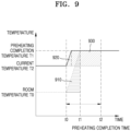
- FIG. 9 is a diagram showing an example of calculating a value of an amount of heat supplied to an aerosol generating material by extending a preheating completion time, according to an embodiment.
- T 0 is room temperature (e.g., 25 °C), and before an aerosol generating device supplies power to a heater, a current temperature T 2 of the heater is higher than T 0 .
- the current temperature T 2 of the heater may be 80 °C.
- a preheating completion temperature T 1 may be a certain temperature between 300 °C and 600 °C. The heater starts preheating from t 0 .
- the value of the amount of heat supplied to the aerosol generating material is a first area value 910 until the temperature of the heater reaches the preheating completion temperature T 1 .
- the first area value 910 is a value of an amount of heat required to be supplied to the aerosol generating material to generate an adequate amount of aerosol.
- the value of the amount of heat supplied to the aerosol generating material is a second area value 920. Since the second area value 920 is less than the first area value 910, when the heater temperature is T 2 , power is supplied to the heater. Therefore, even when the heater temperature reaches the preheating completion temperature T 1 , the value of the amount of heat supplied to the aerosol generating material may not reach the value of the amount of heat required to be supplied to the aerosol generating material. In that case, the amount of heat applied to the aerosol production may be insufficient, and thus the amount of atomization may be insufficient or an appropriate tobacco taste may not be produced.
- the aerosol generating device may extend the preheating completion time from t 1 to t 2 while preheating the heater, such that the value of the amount of heat supplied to the aerosol generating material reaches the value of the amount of heat required to be supplied to the aerosol generating material.
- the value of the amount of heat supplied to the aerosol generating material is the sum of the second area value 920 and a third area value 930.
- the value of the amount of heat supplied to the aerosol generating material may reach the value of the amount of heat required to be supplied to the aerosol generating material during the time required for preheating t 0 -t 2 .
- the aerosol generating device may calculate a value of the amount of heat supplied to the heater, based on the power amount data of the battery capacity measurement IC to determine whether or not the calculated value of the amount of heat supplied to the heater reaches the value of the required amount of heat.
- the aerosol generating device may output a preheating completion signal through an interface.
- the aerosol generating device may set the preheating completion time by using a lookup table stored in a memory.
- the preheating completion time according to the initial temperature of the heater may be matched and stored in the lookup table.
- the aerosol generating device may measure the initial temperature of the heater by using a temperature sensor, and may obtain the preheating completion time matching the initial temperature of the heater measured from the lookup table, thereby supplying power to the heater until the obtained preheating completion time.
- the heater temperature is consistently increased between t 0 and t 1 , and the heater temperature is maintained at T 1 after t 1 , but the heater temperature may be changed in various ways based on a temperature profile of the heater.
- FIG. 10 is a diagram showing an example of calculating a value of an amount of heat supplied to an aerosol generating material by increasing a preheating completion temperature, according to an embodiment.
- T 0 is room temperature (e.g., 25 °C), and a current temperature T 2 of a heater is higher than T 0 before an aerosol generating device supplies power to the heater.
- the current temperature T 2 of the heater may be 80 °C.
- a preheating completion temperature T 1 may be a certain temperature between 300 °C and 600 °C. The heater starts preheating from t 0 .
- a value of an amount of heat supplied to the aerosol generating material is a first area value 1010 until the temperature of the heater reaches the preheating completion temperature T 1 .
- the first area value 1010 is a value of an amount of heat required to be supplied to the aerosol generating material to generate an adequate amount of aerosol.
- the value of the amount of heat supplied to the aerosol generating material to reach the preheating completion temperature T 1 is less than the first area value 1010.
- the heater temperature is T 2
- power is supplied to the heater. Therefore, even when the heater temperature reaches the preheating completion temperature T 1 , the value of the amount of heat supplied to the aerosol generating material may not reach the value of the amount of heat required to be supplied to the aerosol generating material. In that case, the amount of heat applied to the aerosol production may be insufficient, and thus the amount of atomization may be insufficient or an appropriate tobacco taste may not be produced.
- the aerosol generating device may increase the preheating completion temperature from T 1 to T 2 while preheating the heater, such that the value of the amount of heat supplied to the aerosol generating material reaches the value of the amount of heat required to be supplied to the aerosol generating material.
- the value of the amount of heat supplied to the aerosol generating material is a second area value 1020.
- the value of the amount of heat supplied to the aerosol generating material may reach the value of the amount of heat required to be supplied to the aerosol generating material by increasing the preheating completion temperature.
- the aerosol generating device may calculate the value of the amount of heat supplied to the heater, based on the power amount data of the battery capacity measurement IC to determine whether or not the calculated value of the amount of heat supplied to the heater reaches the value of the required amount of heat.
- the aerosol generating device may output a preheating completion signal through an interface.
- the aerosol generating device may set the preheating completion temperature by using a lookup table stored in a memory.
- the preheating completion temperature according to the initial temperature of the heater may be matched and stored in the lookup table.
- the aerosol generating device may measure the initial temperature of the heater by using a temperature sensor, and may supply power to the heater such that the temperature of the heater reaches the obtained preheating completion temperature by obtaining the preheating completion temperature matching the initial temperature of the heater measured from the lookup table.
- the aerosol generating device may extend a preheating completion time and increase the preheating completion temperature.
- the preheating completion time and the preheating completion temperature according to the initial temperature of the heater may be matched and stored in the lookup table.
- the aerosol generating device may measure the initial temperature of the heater by using the temperature sensor, and may obtain the preheating completion time and the preheating completion temperature matching the initial temperature of the heater measured from the lookup table.
- the aerosol generating device may supply power to the heater, based on the obtained preheating completion time and preheating completion temperature.
- the heater temperature is consistently increased between t 0 and t 1 , and the heater temperature is maintained at T 1 after t 1 , but the heater temperature may be changed in various ways based on a temperature profile of the heater.
- the above-described method may be written in a computer program, and may be implemented in a general-purpose digital computer that operates the computer program by using a computer-readable recording medium.
- the structure of data used in the above-described method may be recorded on a computer-readable recording medium through various means.
- the computer-readable recording medium includes storage media such as magnetic storage media (e.g., read only memory (ROM), random access memory (RAM), universal serial bus (USB), floppy disk, hard disk, etc.) and optical reading media (e.g., compact disc (CD)-ROM, digital versatile disc (DVD), etc.) .
Landscapes
- Physics & Mathematics (AREA)
- General Physics & Mathematics (AREA)
- Engineering & Computer Science (AREA)
- Automation & Control Theory (AREA)
- Secondary Cells (AREA)
- Charge And Discharge Circuits For Batteries Or The Like (AREA)
- Control Of Resistance Heating (AREA)
- Control Of Temperature (AREA)
Applications Claiming Priority (3)
| Application Number | Priority Date | Filing Date | Title |
|---|---|---|---|
| KR1020180077889A KR102389828B1 (ko) | 2018-07-04 | 2018-07-04 | 에어로졸 생성 장치 및 이를 제어하는 방법 |
| PCT/KR2019/008020 WO2020009412A1 (ko) | 2018-07-04 | 2019-07-02 | 에어로졸 생성 장치 및 이를 제어하는 방법 |
| EP19829781.4A EP3818857B1 (de) | 2018-07-04 | 2019-07-02 | Aerosolerzeugungsvorrichtung und verfahren zur steuerung davon |
Related Parent Applications (1)
| Application Number | Title | Priority Date | Filing Date |
|---|---|---|---|
| EP19829781.4A Division EP3818857B1 (de) | 2018-07-04 | 2019-07-02 | Aerosolerzeugungsvorrichtung und verfahren zur steuerung davon |
Publications (2)
| Publication Number | Publication Date |
|---|---|
| EP4570098A2 true EP4570098A2 (de) | 2025-06-18 |
| EP4570098A3 EP4570098A3 (de) | 2025-08-20 |
Family
ID=69060416
Family Applications (2)
| Application Number | Title | Priority Date | Filing Date |
|---|---|---|---|
| EP25174030.4A Pending EP4570098A3 (de) | 2018-07-04 | 2019-07-02 | Aerosolerzeugungsvorrichtung und verfahren zur steuerung davon |
| EP19829781.4A Active EP3818857B1 (de) | 2018-07-04 | 2019-07-02 | Aerosolerzeugungsvorrichtung und verfahren zur steuerung davon |
Family Applications After (1)
| Application Number | Title | Priority Date | Filing Date |
|---|---|---|---|
| EP19829781.4A Active EP3818857B1 (de) | 2018-07-04 | 2019-07-02 | Aerosolerzeugungsvorrichtung und verfahren zur steuerung davon |
Country Status (6)
| Country | Link |
|---|---|
| US (2) | US12302950B2 (de) |
| EP (2) | EP4570098A3 (de) |
| JP (1) | JP7056850B2 (de) |
| KR (1) | KR102389828B1 (de) |
| CN (1) | CN112334026B (de) |
| WO (1) | WO2020009412A1 (de) |
Families Citing this family (22)
| Publication number | Priority date | Publication date | Assignee | Title |
|---|---|---|---|---|
| KR20210092082A (ko) * | 2020-01-15 | 2021-07-23 | 주식회사 케이티앤지 | 자동으로 가열 동작을 수행하는 에어로졸 생성 장치 |
| KR102326985B1 (ko) * | 2020-02-05 | 2021-11-16 | 주식회사 케이티앤지 | 에어로졸 생성 장치 및 시스템 |
| KR102522678B1 (ko) * | 2020-12-31 | 2023-04-17 | 주식회사 케이티앤지 | 에어로졸 생성 장치 |
| US11789476B2 (en) | 2021-01-18 | 2023-10-17 | Altria Client Services Llc | Heat-not-burn (HNB) aerosol-generating devices including intra-draw heater control, and methods of controlling a heater |
| US12520880B2 (en) | 2021-01-18 | 2026-01-13 | Altria Client Services Llc | Heat-not-burn (HNB) aerosol-generating devices including energy based heater control, and methods of controlling a heater |
| CN113050513A (zh) * | 2021-03-29 | 2021-06-29 | 深圳市吉迩科技有限公司 | 一种气溶胶发生装置及其控制系统、控制方法 |
| KR102625768B1 (ko) * | 2021-06-14 | 2024-01-16 | 주식회사 케이티앤지 | 에어로졸 생성 장치 및 그 제어 방법 |
| KR102644193B1 (ko) * | 2021-07-28 | 2024-03-06 | 주식회사 케이티앤지 | 에어로졸 생성 물품에 대한 예열 동작을 제어하는 에어로졸 생성 장치 및 그의 동작 방법 |
| KR102697383B1 (ko) * | 2021-09-02 | 2024-08-22 | 주식회사 케이티앤지 | 히터에 대한 전력 공급을 제어하는 에어로졸 생성 장치 및 그의 동작 방법 |
| JP7789797B2 (ja) * | 2021-10-29 | 2025-12-22 | 日本たばこ産業株式会社 | 吸引装置、基材、及び制御方法 |
| JP2024544255A (ja) * | 2021-12-15 | 2024-11-28 | フィリップ・モーリス・プロダクツ・ソシエテ・アノニム | 温度に基づく制御を有するエアロゾル発生装置 |
| KR102686085B1 (ko) * | 2021-12-29 | 2024-07-22 | 주식회사 케이티앤지 | 에어로졸 생성 방법 및 그 방법을 수행하는 전자 장치 |
| KR102686407B1 (ko) * | 2022-01-19 | 2024-07-19 | 주식회사 케이티앤지 | 에어로졸 생성 물품을 예열하는 에어로졸 생성 장치 및 그의 동작 방법 |
| EP4480335A4 (de) * | 2022-02-17 | 2026-02-11 | Japan Tobacco Inc | Geschmacksinhalator oder aerosolerzeugungsvorrichtung, steuerungsverfahren dafür und programm dafür |
| CN118714940A (zh) * | 2022-03-24 | 2024-09-27 | 日本烟草产业株式会社 | 气溶胶生成系统、控制方法、以及程序 |
| JP7720476B2 (ja) * | 2022-03-24 | 2025-08-07 | 日本たばこ産業株式会社 | エアロゾル生成システム、制御方法、及びプログラム |
| EP4467028A4 (de) * | 2022-03-24 | 2025-12-03 | Japan Tobacco Inc | Aerosolerzeugungssystem, steuerungsverfahren und programm |
| CN114617297A (zh) * | 2022-04-12 | 2022-06-14 | 深圳麦时科技有限公司 | 气溶胶生成装置及其控制方法和装置、计算机存储介质 |
| EP4319586A4 (de) * | 2022-06-16 | 2024-10-30 | KT&G Corporation | Aerosolerzeugungsvorrichtung und betriebsverfahren dafür |
| CN116602460A (zh) * | 2023-05-05 | 2023-08-18 | 深圳市合元科技有限公司 | 气溶胶生成装置的控制方法和气溶胶生成装置 |
| CN121264721A (zh) * | 2024-07-04 | 2026-01-06 | 深圳市合元科技有限公司 | 一种气溶胶生成装置的控制方法 |
| CN120335529B (zh) * | 2025-05-07 | 2026-03-24 | 深圳市业丰新能源科技有限公司 | 一种陶瓷覆铜板加工的温度控制系统 |
Family Cites Families (37)
| Publication number | Priority date | Publication date | Assignee | Title |
|---|---|---|---|---|
| US5372148A (en) * | 1993-02-24 | 1994-12-13 | Philip Morris Incorporated | Method and apparatus for controlling the supply of energy to a heating load in a smoking article |
| JP2949114B1 (ja) | 1998-08-04 | 1999-09-13 | 日本たばこ産業株式会社 | 電気式香味生成物品加熱制御装置 |
| JP3929234B2 (ja) * | 2000-07-28 | 2007-06-13 | 富士フイルム株式会社 | 予熱温度の制御装置および制御方法 |
| KR101468449B1 (ko) * | 2007-04-26 | 2014-12-04 | 주식회사 케이티앤지생명과학 | 신규한 페난스렌퀴논계 화합물 및 이를 포함하는대사증후군 질환의 치료 또는 예방용 약제 조성물 |
| EP2110033A1 (de) | 2008-03-25 | 2009-10-21 | Philip Morris Products S.A. | Verfahren zum Steuern der Bildung von Rauchbestandteilen in einem elektrischen Aerosolerzeugungssystem |
| EP2454956A1 (de) | 2010-11-19 | 2012-05-23 | Philip Morris Products S.A. | Elektrisch beheiztes Rauchsystem mit mindestens zwei Einheiten |
| EP2672848A4 (de) * | 2011-02-09 | 2017-12-06 | SIS Resources, Ltd. | Elektronische zigarette mit variabler leistungssteuerung |
| HUE040751T2 (hu) * | 2011-10-27 | 2019-03-28 | Philip Morris Products Sa | Aeroszol-fejlesztõ rendszer továbbfejlesztett aeroszol-elõállítással |
| TWI546023B (zh) * | 2011-10-27 | 2016-08-21 | 菲利浦莫里斯製品股份有限公司 | 具有氣溶膠生產控制之電操作氣溶膠產生系統 |
| US8881737B2 (en) * | 2012-09-04 | 2014-11-11 | R.J. Reynolds Tobacco Company | Electronic smoking article comprising one or more microheaters |
| HUE031223T2 (en) | 2012-09-11 | 2017-07-28 | Philip Morris Products Sa | Device and method for controlling electric heating element for controlling temperature |
| CN102940313B (zh) * | 2012-11-13 | 2015-04-01 | 卓尔悦(常州)电子科技有限公司 | 电子烟的智能控制器及方法 |
| TWI608805B (zh) | 2012-12-28 | 2017-12-21 | 菲利浦莫里斯製品股份有限公司 | 加熱型氣溶膠產生裝置及用於產生具有一致性質的氣溶膠之方法 |
| WO2015107552A1 (en) | 2014-01-17 | 2015-07-23 | Godfrey Phillips India Limited | Device and method of vaporizing a liquid material |
| US10285430B2 (en) * | 2014-02-28 | 2019-05-14 | Ayr Ltd. | Electronic vaporiser system |
| US11825565B2 (en) | 2014-06-14 | 2023-11-21 | Evolv, Llc | Electronic vaporizer having temperature sensing and limit |
| WO2016082183A1 (zh) * | 2014-11-28 | 2016-06-02 | 惠州市吉瑞科技有限公司 | 一种雾化器发热丝温度测控装置、测控方法和一种电子烟 |
| CN104571191B (zh) * | 2015-01-22 | 2018-01-02 | 卓尔悦欧洲控股有限公司 | 温控系统及其电子烟 |
| WO2016145634A1 (zh) | 2015-03-18 | 2016-09-22 | 惠州市吉瑞科技有限公司 | 一种电子烟雾化器发热丝加热方法和电子烟 |
| GB2537121A (en) | 2015-04-07 | 2016-10-12 | Cigtronica Ltd | Inhalation device |
| MY186867A (en) * | 2015-04-15 | 2021-08-26 | Philip Morris Products Sa | Device and method for controlling an electrical heater to limit temperature according to desired temperature profile over time |
| US10154689B2 (en) * | 2015-06-30 | 2018-12-18 | R.J. Reynolds Tobacco Company | Heat generation segment for an aerosol-generation system of a smoking article |
| US10912333B2 (en) * | 2016-02-25 | 2021-02-09 | Juul Labs, Inc. | Vaporization device control systems and methods |
| US10405582B2 (en) * | 2016-03-10 | 2019-09-10 | Pax Labs, Inc. | Vaporization device with lip sensing |
| US10375993B2 (en) * | 2016-03-21 | 2019-08-13 | Altria Client Services Llc | E-vaping device cartridge with internal infrared sensor |
| WO2017185355A1 (zh) | 2016-04-29 | 2017-11-02 | 惠州市吉瑞科技有限公司深圳分公司 | 一种检测电子烟中烟油是否耗尽的方法 |
| CN106102493B (zh) * | 2016-06-24 | 2020-01-10 | 惠州市吉瑞科技有限公司深圳分公司 | 一种电子烟控制方法 |
| AR109120A1 (es) | 2016-07-26 | 2018-10-31 | British American Tobacco Investments Ltd | Aparato para calentar material fumable |
| CN106418702A (zh) | 2016-09-06 | 2017-02-22 | 深圳市合元科技有限公司 | 一种电子烟及其温度控制方法和装置 |
| US20180132526A1 (en) * | 2016-11-11 | 2018-05-17 | Rai Strategic Holdings, Inc. | Real-time temperature control for an aerosol delivery device |
| JP7053600B2 (ja) * | 2016-11-18 | 2022-04-12 | フィリップ・モーリス・プロダクツ・ソシエテ・アノニム | エアロゾル形成基体を加熱するための加熱組立品、エアロゾル発生装置および方法 |
| TW201818833A (zh) * | 2016-11-22 | 2018-06-01 | 瑞士商菲利浦莫里斯製品股份有限公司 | 感應加熱裝置、包含感應加熱裝置之氣溶膠產生系統及其操作方法 |
| CN111713750B (zh) | 2016-12-16 | 2023-09-05 | 韩国烟草人参公社 | 气溶胶生成系统 |
| KR102138873B1 (ko) * | 2016-12-16 | 2020-07-29 | 주식회사 케이티앤지 | 히터를 사전예열하는 에어로졸 생성 시스템 |
| CN206808677U (zh) * | 2017-05-10 | 2017-12-29 | 深圳市合元科技有限公司 | 可温度校准的电磁加热电子烟 |
| CN107095343B (zh) * | 2017-05-24 | 2020-05-12 | 惠州市新泓威科技有限公司 | 电子烟具的加热方法 |
| CN107156915A (zh) | 2017-06-26 | 2017-09-15 | 常州市派腾电子技术服务有限公司 | 一种电子烟及电子烟的预热方法 |
-
2018
- 2018-07-04 KR KR1020180077889A patent/KR102389828B1/ko active Active
-
2019
- 2019-07-02 US US17/253,351 patent/US12302950B2/en active Active
- 2019-07-02 EP EP25174030.4A patent/EP4570098A3/de active Pending
- 2019-07-02 WO PCT/KR2019/008020 patent/WO2020009412A1/ko not_active Ceased
- 2019-07-02 JP JP2020572890A patent/JP7056850B2/ja active Active
- 2019-07-02 EP EP19829781.4A patent/EP3818857B1/de active Active
- 2019-07-02 CN CN201980043310.2A patent/CN112334026B/zh active Active
-
2025
- 2025-04-21 US US19/184,280 patent/US20250241379A1/en active Pending
Also Published As
| Publication number | Publication date |
|---|---|
| CN112334026B (zh) | 2023-10-31 |
| US20210251299A1 (en) | 2021-08-19 |
| EP4570098A3 (de) | 2025-08-20 |
| CN112334026A (zh) | 2021-02-05 |
| US12302950B2 (en) | 2025-05-20 |
| EP3818857B1 (de) | 2025-05-28 |
| JP2021528980A (ja) | 2021-10-28 |
| EP3818857A1 (de) | 2021-05-12 |
| WO2020009412A1 (ko) | 2020-01-09 |
| US20250241379A1 (en) | 2025-07-31 |
| EP3818857A4 (de) | 2021-12-01 |
| KR102389828B1 (ko) | 2022-04-22 |
| KR20200004697A (ko) | 2020-01-14 |
| JP7056850B2 (ja) | 2022-04-19 |
Similar Documents
| Publication | Publication Date | Title |
|---|---|---|
| EP3818857B1 (de) | Aerosolerzeugungsvorrichtung und verfahren zur steuerung davon | |
| EP3820244B1 (de) | Aerosolgenerator sowie verfahren und vorrichtung zum senden und empfangen von daten | |
| KR20200005082A (ko) | 에어로졸 생성 장치 및 방법 | |
| CN113507850B (zh) | 气溶胶生成装置和气溶胶生成系统 | |
| KR102142635B1 (ko) | 전력을 공급하는 방법 및 그 디바이스 | |
| KR102367432B1 (ko) | 에어로졸 생성장치 및 에어로졸 생성장치의 퍼프인식 방법 | |
| KR20180085365A (ko) | 가열 방식의 미세 입자 발생 장치 | |
| KR102400621B1 (ko) | 에어로졸을 생성하는 장치 및 방법 | |
| KR102330293B1 (ko) | 에어로졸 생성 장치 | |
| KR20200030373A (ko) | 다단 히터를 포함하는 에어로졸 생성 장치 | |
| KR102493441B1 (ko) | 에어로졸 생성 장치 | |
| KR102442048B1 (ko) | 에어로졸 생성장치 및 에어로졸 생성장치의 동작제어 방법 | |
| KR102372336B1 (ko) | 에어로졸을 생성하는 장치 및 방법 | |
| KR102330294B1 (ko) | 에어로졸 생성장치의 배터리의 보호 방법 및 그 장치 | |
| RU2855137C2 (ru) | Устройство для генерирования аэрозоля | |
| RU2793701C1 (ru) | Устройство и система для генерирования аэрозоля | |
| KR20200005080A (ko) | 에어로졸 생성 장치 | |
| KR20200005079A (ko) | 에어로졸 생성 장치 | |
| KR20190038180A (ko) | 충전 방법 및 디바이스 | |
| KR20260015306A (ko) | 에어로졸 발생 시스템의 충전 관리 개선 |
Legal Events
| Date | Code | Title | Description |
|---|---|---|---|
| PUAI | Public reference made under article 153(3) epc to a published international application that has entered the european phase |
Free format text: ORIGINAL CODE: 0009012 |
|
| STAA | Information on the status of an ep patent application or granted ep patent |
Free format text: STATUS: THE APPLICATION HAS BEEN PUBLISHED |
|
| AC | Divisional application: reference to earlier application |
Ref document number: 3818857 Country of ref document: EP Kind code of ref document: P |
|
| AK | Designated contracting states |
Kind code of ref document: A2 Designated state(s): AL AT BE BG CH CY CZ DE DK EE ES FI FR GB GR HR HU IE IS IT LI LT LU LV MC MK MT NL NO PL PT RO RS SE SI SK SM TR |
|
| PUAL | Search report despatched |
Free format text: ORIGINAL CODE: 0009013 |
|
| AK | Designated contracting states |
Kind code of ref document: A3 Designated state(s): AL AT BE BG CH CY CZ DE DK EE ES FI FR GB GR HR HU IE IS IT LI LT LU LV MC MK MT NL NO PL PT RO RS SE SI SK SM TR |
|
| RIC1 | Information provided on ipc code assigned before grant |
Ipc: A24F 40/57 20200101AFI20250714BHEP Ipc: A24F 40/20 20200101ALN20250714BHEP |
|
| STAA | Information on the status of an ep patent application or granted ep patent |
Free format text: STATUS: REQUEST FOR EXAMINATION WAS MADE |
|
| 17P | Request for examination filed |
Effective date: 20260114 |
|
| GRAP | Despatch of communication of intention to grant a patent |
Free format text: ORIGINAL CODE: EPIDOSNIGR1 |
|
| STAA | Information on the status of an ep patent application or granted ep patent |
Free format text: STATUS: GRANT OF PATENT IS INTENDED |
|
| RIC1 | Information provided on ipc code assigned before grant |
Ipc: A24F 40/57 20200101AFI20260218BHEP Ipc: A24F 40/20 20200101ALN20260218BHEP |
|
| RIC1 | Information provided on ipc code assigned before grant |
Ipc: A24F 40/57 20200101AFI20260302BHEP Ipc: A24F 40/20 20200101ALN20260302BHEP |
|
| INTG | Intention to grant announced |
Effective date: 20260313 |