EP4563902A1 - Klimaanlage - Google Patents
Klimaanlage Download PDFInfo
- Publication number
- EP4563902A1 EP4563902A1 EP24216243.6A EP24216243A EP4563902A1 EP 4563902 A1 EP4563902 A1 EP 4563902A1 EP 24216243 A EP24216243 A EP 24216243A EP 4563902 A1 EP4563902 A1 EP 4563902A1
- Authority
- EP
- European Patent Office
- Prior art keywords
- air
- discharge
- guide
- conditioner
- vanes
- Prior art date
- Legal status (The legal status is an assumption and is not a legal conclusion. Google has not performed a legal analysis and makes no representation as to the accuracy of the status listed.)
- Pending
Links
Images


Classifications
-
- F—MECHANICAL ENGINEERING; LIGHTING; HEATING; WEAPONS; BLASTING
- F24—HEATING; RANGES; VENTILATING
- F24F—AIR-CONDITIONING; AIR-HUMIDIFICATION; VENTILATION; USE OF AIR CURRENTS FOR SCREENING
- F24F1/00—Room units for air-conditioning, e.g. separate or self-contained units or units receiving primary air from a central station
- F24F1/0007—Indoor units, e.g. fan coil units
- F24F1/0059—Indoor units, e.g. fan coil units characterised by heat exchangers
- F24F1/0063—Indoor units, e.g. fan coil units characterised by heat exchangers by the mounting or arrangement of the heat exchangers
-
- F—MECHANICAL ENGINEERING; LIGHTING; HEATING; WEAPONS; BLASTING
- F24—HEATING; RANGES; VENTILATING
- F24F—AIR-CONDITIONING; AIR-HUMIDIFICATION; VENTILATION; USE OF AIR CURRENTS FOR SCREENING
- F24F1/00—Room units for air-conditioning, e.g. separate or self-contained units or units receiving primary air from a central station
- F24F1/0007—Indoor units, e.g. fan coil units
- F24F1/0011—Indoor units, e.g. fan coil units characterised by air outlets
-
- F—MECHANICAL ENGINEERING; LIGHTING; HEATING; WEAPONS; BLASTING
- F24—HEATING; RANGES; VENTILATING
- F24F—AIR-CONDITIONING; AIR-HUMIDIFICATION; VENTILATION; USE OF AIR CURRENTS FOR SCREENING
- F24F13/00—Details common to, or for air-conditioning, air-humidification, ventilation or use of air currents for screening
- F24F13/08—Air-flow control members, e.g. louvres, grilles, flaps or guide plates
- F24F13/081—Air-flow control members, e.g. louvres, grilles, flaps or guide plates for guiding air around a curve
-
- F—MECHANICAL ENGINEERING; LIGHTING; HEATING; WEAPONS; BLASTING
- F24—HEATING; RANGES; VENTILATING
- F24F—AIR-CONDITIONING; AIR-HUMIDIFICATION; VENTILATION; USE OF AIR CURRENTS FOR SCREENING
- F24F13/00—Details common to, or for air-conditioning, air-humidification, ventilation or use of air currents for screening
- F24F13/08—Air-flow control members, e.g. louvres, grilles, flaps or guide plates
- F24F13/10—Air-flow control members, e.g. louvres, grilles, flaps or guide plates movable, e.g. dampers
-
- F—MECHANICAL ENGINEERING; LIGHTING; HEATING; WEAPONS; BLASTING
- F24—HEATING; RANGES; VENTILATING
- F24F—AIR-CONDITIONING; AIR-HUMIDIFICATION; VENTILATION; USE OF AIR CURRENTS FOR SCREENING
- F24F13/00—Details common to, or for air-conditioning, air-humidification, ventilation or use of air currents for screening
- F24F13/08—Air-flow control members, e.g. louvres, grilles, flaps or guide plates
- F24F13/10—Air-flow control members, e.g. louvres, grilles, flaps or guide plates movable, e.g. dampers
- F24F13/14—Air-flow control members, e.g. louvres, grilles, flaps or guide plates movable, e.g. dampers built up of tilting members, e.g. louvre
-
- F—MECHANICAL ENGINEERING; LIGHTING; HEATING; WEAPONS; BLASTING
- F24—HEATING; RANGES; VENTILATING
- F24F—AIR-CONDITIONING; AIR-HUMIDIFICATION; VENTILATION; USE OF AIR CURRENTS FOR SCREENING
- F24F13/00—Details common to, or for air-conditioning, air-humidification, ventilation or use of air currents for screening
- F24F13/08—Air-flow control members, e.g. louvres, grilles, flaps or guide plates
- F24F13/10—Air-flow control members, e.g. louvres, grilles, flaps or guide plates movable, e.g. dampers
- F24F13/14—Air-flow control members, e.g. louvres, grilles, flaps or guide plates movable, e.g. dampers built up of tilting members, e.g. louvre
- F24F13/1413—Air-flow control members, e.g. louvres, grilles, flaps or guide plates movable, e.g. dampers built up of tilting members, e.g. louvre using more than one tilting member, e.g. with several pivoting blades
-
- F—MECHANICAL ENGINEERING; LIGHTING; HEATING; WEAPONS; BLASTING
- F24—HEATING; RANGES; VENTILATING
- F24F—AIR-CONDITIONING; AIR-HUMIDIFICATION; VENTILATION; USE OF AIR CURRENTS FOR SCREENING
- F24F13/00—Details common to, or for air-conditioning, air-humidification, ventilation or use of air currents for screening
- F24F13/08—Air-flow control members, e.g. louvres, grilles, flaps or guide plates
- F24F13/10—Air-flow control members, e.g. louvres, grilles, flaps or guide plates movable, e.g. dampers
- F24F13/14—Air-flow control members, e.g. louvres, grilles, flaps or guide plates movable, e.g. dampers built up of tilting members, e.g. louvre
- F24F13/1426—Air-flow control members, e.g. louvres, grilles, flaps or guide plates movable, e.g. dampers built up of tilting members, e.g. louvre characterised by actuating means
-
- F—MECHANICAL ENGINEERING; LIGHTING; HEATING; WEAPONS; BLASTING
- F24—HEATING; RANGES; VENTILATING
- F24F—AIR-CONDITIONING; AIR-HUMIDIFICATION; VENTILATION; USE OF AIR CURRENTS FOR SCREENING
- F24F13/00—Details common to, or for air-conditioning, air-humidification, ventilation or use of air currents for screening
- F24F13/08—Air-flow control members, e.g. louvres, grilles, flaps or guide plates
- F24F13/10—Air-flow control members, e.g. louvres, grilles, flaps or guide plates movable, e.g. dampers
- F24F13/14—Air-flow control members, e.g. louvres, grilles, flaps or guide plates movable, e.g. dampers built up of tilting members, e.g. louvre
- F24F13/15—Air-flow control members, e.g. louvres, grilles, flaps or guide plates movable, e.g. dampers built up of tilting members, e.g. louvre with parallel simultaneously tiltable lamellae
-
- F—MECHANICAL ENGINEERING; LIGHTING; HEATING; WEAPONS; BLASTING
- F24—HEATING; RANGES; VENTILATING
- F24F—AIR-CONDITIONING; AIR-HUMIDIFICATION; VENTILATION; USE OF AIR CURRENTS FOR SCREENING
- F24F13/00—Details common to, or for air-conditioning, air-humidification, ventilation or use of air currents for screening
- F24F13/20—Casings or covers
-
- F—MECHANICAL ENGINEERING; LIGHTING; HEATING; WEAPONS; BLASTING
- F24—HEATING; RANGES; VENTILATING
- F24F—AIR-CONDITIONING; AIR-HUMIDIFICATION; VENTILATION; USE OF AIR CURRENTS FOR SCREENING
- F24F13/00—Details common to, or for air-conditioning, air-humidification, ventilation or use of air currents for screening
- F24F13/22—Means for preventing condensation or evacuating condensate
- F24F13/222—Means for preventing condensation or evacuating condensate for evacuating condensate
-
- F—MECHANICAL ENGINEERING; LIGHTING; HEATING; WEAPONS; BLASTING
- F24—HEATING; RANGES; VENTILATING
- F24F—AIR-CONDITIONING; AIR-HUMIDIFICATION; VENTILATION; USE OF AIR CURRENTS FOR SCREENING
- F24F13/00—Details common to, or for air-conditioning, air-humidification, ventilation or use of air currents for screening
- F24F13/24—Means for preventing or suppressing noise
-
- F—MECHANICAL ENGINEERING; LIGHTING; HEATING; WEAPONS; BLASTING
- F24—HEATING; RANGES; VENTILATING
- F24F—AIR-CONDITIONING; AIR-HUMIDIFICATION; VENTILATION; USE OF AIR CURRENTS FOR SCREENING
- F24F1/00—Room units for air-conditioning, e.g. separate or self-contained units or units receiving primary air from a central station
- F24F1/0007—Indoor units, e.g. fan coil units
- F24F1/0011—Indoor units, e.g. fan coil units characterised by air outlets
- F24F1/0014—Indoor units, e.g. fan coil units characterised by air outlets having two or more outlet openings
-
- F—MECHANICAL ENGINEERING; LIGHTING; HEATING; WEAPONS; BLASTING
- F24—HEATING; RANGES; VENTILATING
- F24F—AIR-CONDITIONING; AIR-HUMIDIFICATION; VENTILATION; USE OF AIR CURRENTS FOR SCREENING
- F24F1/00—Room units for air-conditioning, e.g. separate or self-contained units or units receiving primary air from a central station
- F24F1/0007—Indoor units, e.g. fan coil units
- F24F1/0043—Indoor units, e.g. fan coil units characterised by mounting arrangements
- F24F1/0047—Indoor units, e.g. fan coil units characterised by mounting arrangements mounted in the ceiling or at the ceiling
-
- F—MECHANICAL ENGINEERING; LIGHTING; HEATING; WEAPONS; BLASTING
- F24—HEATING; RANGES; VENTILATING
- F24F—AIR-CONDITIONING; AIR-HUMIDIFICATION; VENTILATION; USE OF AIR CURRENTS FOR SCREENING
- F24F13/00—Details common to, or for air-conditioning, air-humidification, ventilation or use of air currents for screening
- F24F13/08—Air-flow control members, e.g. louvres, grilles, flaps or guide plates
- F24F13/10—Air-flow control members, e.g. louvres, grilles, flaps or guide plates movable, e.g. dampers
- F24F13/14—Air-flow control members, e.g. louvres, grilles, flaps or guide plates movable, e.g. dampers built up of tilting members, e.g. louvre
- F24F13/1426—Air-flow control members, e.g. louvres, grilles, flaps or guide plates movable, e.g. dampers built up of tilting members, e.g. louvre characterised by actuating means
- F24F2013/1473—Air-flow control members, e.g. louvres, grilles, flaps or guide plates movable, e.g. dampers built up of tilting members, e.g. louvre characterised by actuating means with cams or levers
-
- F—MECHANICAL ENGINEERING; LIGHTING; HEATING; WEAPONS; BLASTING
- F24—HEATING; RANGES; VENTILATING
- F24F—AIR-CONDITIONING; AIR-HUMIDIFICATION; VENTILATION; USE OF AIR CURRENTS FOR SCREENING
- F24F13/00—Details common to, or for air-conditioning, air-humidification, ventilation or use of air currents for screening
- F24F13/24—Means for preventing or suppressing noise
- F24F2013/247—Active noise-suppression
-
- F—MECHANICAL ENGINEERING; LIGHTING; HEATING; WEAPONS; BLASTING
- F24—HEATING; RANGES; VENTILATING
- F24F—AIR-CONDITIONING; AIR-HUMIDIFICATION; VENTILATION; USE OF AIR CURRENTS FOR SCREENING
- F24F2221/00—Details or features not otherwise provided for
- F24F2221/17—Details or features not otherwise provided for mounted in a wall
Definitions
- the present disclosure relates to an air-conditioner, and more particularly, to an air-conditioner having a guide module for controlling a discharge wind direction.
- Air-conditioners control the temperature of indoor air to a temperature set by a user and cool and heat indoor air according to the principle of a refrigeration cycle.
- an air-conditioner in which an indoor unit is installed vertically in an indoor space is referred to as a stand-alone air-conditioner
- an air-conditioner in which an indoor unit is installed on an indoor wall is referred to as a wall-mounted air-conditioner
- an air-conditioner in which an indoor unit is installed on an indoor ceiling is referred to as a ceiling-type air-conditioner.
- the ⁇ link structure of an air-conditioner' disclosed in Korean Application Publication No. 10-1998-0049068 includes a plurality of louvers coupled to a discharge port side; and a link that integrally rotates the plurality of louvers, in which the plurality of louvers are formed in a flat plate shape with a uniform thickness throughout.
- the plurality of louvers move to form a discharge flow path and come closer to an inner wall to adjust a wind direction.
- the louver located at the edge among the plurality of louvers moves closer to the inner wall, and a flow path between the louver at the edge and the inner wall becomes narrow, causing a vortex. This causes a problem in that a discharged air flow does not flow smoothly.
- the related art air-conditioner has a problem in that the vortex occurring at the edge of the discharge flow path is not discharged quickly through the discharge port due to the plurality of louvers, causing dew formation on the louvers.
- the related art air-conditioner has a problem in that bacteria, such as mold, grow due to condensate formed in the louvers. This may cause an unpleasant odor occurring in the discharged air flow.
- the disclosure provides an air-conditioner forming a smooth air flow.
- the present disclosure also provides an air-conditioner with reduced vortex occurrence.
- the disclosure also provides an air-conditioner with improved hygiene performance.
- the disclosure also provides an air-conditioner with reduced dew formation.
- the disclosure also provides an air-conditioner with improved comfort of discharged air flow.
- the disclosure also provides a guide module structure of an air-conditioner that controls a flow direction of discharged air flow.
- the disclosure also provides a guide module structure of an air-conditioner with improved durability.
- an air-conditioner includes: a case including an intake port and a discharge port; a fan disposed inside the case and forming an air flow; an indoor heat exchanger heat-exchanging air inside the case with a refrigerant; and a guide module disposed downstream of the fan and guiding the air flow flowing to the discharge port, wherein the guide module includes a plurality of vanes arranged in a row in a discharge flow path formed between the discharge port and the fan, the plurality of vanes include a pair of first vanes spaced apart from each other; and a plurality of second vanes arranged between the pair of first vanes.
- At least one first vane of the pair of first vanes includes a one or more communication holes formed in a penetrating manner.
- the communication holes may be called through holes.
- both vanes of the pair of first vanes includes at least one communication hole formed in a penetrating manner, so that a discharged air flow may flow by passing through the pair of first vanes through the communication hole.
- the communication hole may include a plurality of communication holes arranged in a direction intersecting a flow direction of the air flow flowing through the discharge flow path.
- the plurality of communication holes may be elongated in a direction parallel to the flow direction of the air flow flowing through the discharge flow path.
- a width of the plurality of communication holes intersecting a length direction may be greater than a spacing between the plurality of communication holes.
- the plurality of vanes may include: a fixed portion fixed to the discharge flow path; a movable portion moving in a direction intersecting the flow direction of the air flow flowing through the discharge flow path; and a connecting portion connecting the fixed portion to the movable portion.
- the communication hole may be formed in the movable portion of the pair of first vanes.
- a thickness of the connecting portion may be thinner than a thickness of the moving portion.
- the connecting portion may be formed to be more flexible than the movable portion.
- the guide module may include a link connected to the plurality of vanes and moving in a direction intersecting the flow direction of the air flow flowing through the discharge flow path.
- the movable portion may include a coupling slot in which the link is disposed.
- the coupling slot may be elongated in a direction parallel to the flow direction of the air flow flowing through the discharge flow path, so that the discharged air flow may pass through the coupling slot.
- the communication hole may include a plurality of communication holes arranged in a direction intersecting the flow direction of the air flow flowing through the discharge flow path.
- the coupling slot may be disposed in a row with the plurality of communication holes.
- the movable portion may include a coupling pillar formed in the coupling slot.
- the link may include a coupling recess coupled to the coupling pillar.
- a thickness of the fixed portion may be thicker than a thickness of the connecting portion, thereby increasing a fixed area.
- the connecting portion may be bent as the moving portion moves.
- the connecting portion may include: a first connecting portion connecting the movable portion to the fixed portion; and a second connecting portion extending from the movable portion toward the fixed portion and spaced apart from the fixed portion.
- the connecting portion may include a slit formed between the first connecting portion and the second connecting portion.
- An edge of the second connecting portion facing the fixed portion may be formed to be curved.
- a pair of first vanes located at an edge are formed with a communication hole, so that a vortex occurring at the edge may flow to a discharge port through a communication hole.
- the occurrence of the vortex may be reduced, so that the discharged air flow may flow smoothly. Accordingly, the amount of dew formed on the guide module may be reduced.
- the rigidity of the pair of first vanes may be improved due to the plurality of communication holes disposed in the vertical direction.
- the vortex may smoothly flow in a flow direction of the air flow and be discharged to the discharge port due to the plurality of communication holes elongated in a direction parallel to the flow direction of the air flow.
- a thickness of the connecting portion is formed thinner than a thickness of the movable portion, so that the flexibility of the vane may be improved. Accordingly, the movable portion may flexibly move in the left-right direction with respect to the fixed portion.
- the vortex that occurs may flow to the discharge port by passing through the vane through the coupling slot.
- the thickness of the fixed portion is thicker than the thickness of the connecting portion, so that fixing force of the vane may be improved.
- the connecting portion includes the first connecting portion that connects the movable portion to the fixed portion and the second connecting portion not connected to the fixed portion, so that fatigue applied to the connecting portion when the movable portion moves in the left-right direction may be reduced. As a result, the durability of the guide module may be improved.
- the slit is formed between the first connecting portion and the second connecting portion, so that interference between the first connecting portion and the second connecting portion may be reduced when the movable portion moves in the left-right direction. As a result, noise and friction occurring from the guide module may be reduced.
- the edge of the second connecting portion facing the fixed portion is formed to be curved, so that the discharged air flow passing through the guide module may flow smoothly.
- a singular form may include a plural form if there is no clearly opposite meaning in the context.
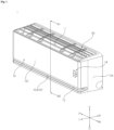
- An air-conditioner 1 is described with reference to FIG. 1 .
- the air-conditioner 1 may include a case 10 in which an intake port 11 and a discharge port 12 are formed.
- the case 10 may form an outer shape of the air-conditioner 1.
- the case 10 may be elongated.
- the case 10 may have an internal space in which a refrigeration cycle device is accommodated.
- the case 10 may include a front wall 102 forming a front surface.
- the front wall 102 may face an indoor space.
- the front wall 102 may face the front.
- the case 10 may include a sidewall 104 forming a side surface.
- the sidewall 104 may cover a side surface of the case 10.
- the sidewall 104 may be connected to the front wall 102.
- the sidewall 104 may include a pair of sidewalls 104 bent from the front wall 102.
- the intake port 11 may be formed in the case 10.
- the intake port 11 may be formed on one surface of the case 10.
- the intake port 11 may be opened on an upper surface of the case 10.
- the intake port 11 may be open upwardly in the case 10. Through this, indoor air may be introduced into the interior of the case 10 through the intake port 11.
- the discharge port 12 may be formed in the case 10.
- the discharge port 12 may be formed on the other surface of the case 10.
- the discharge port 12 may include a first discharge port 12a formed on the front wall 102 of the case 10.
- the discharge port 12 may be elongated.
- the first discharge port 12a opened forwardly on the front wall 102 of the case 10 may be elongated in a left-right direction.
- Air inside the case 10 may be discharged into an indoor space through the discharge port 12.
- air introduced through the intake port 11 may be discharged through the discharge port 12.
- air inside the case 10 may be discharged to the front of the air-conditioner 1 through the first discharge port 12a.
- the air-conditioner 1 may include a filter 20 disposed in the intake port 11.
- the filter 20 may have a shape corresponding to a shape of the intake port 11.
- the filter 20 may purify air introduced into the intake port 11.
- the air-conditioner 1 may include a discharge vane disposed in the discharge port 12.
- the discharge vane may guide an air flow discharged through the discharge port 12.
- the discharge vane may be elongated in a length direction of the discharge port 12.
- the discharge vane may include a first discharge vane 13 disposed in the first discharge port 12a.
- the first discharge vane 13 may be fixed to the first discharge port 12a.
- the first discharge port 12a may be maintained in a normally open state.
- the first discharge vane 13 may guide the air flow discharged through the first discharge port 12a forwardly.
- the air-conditioner 1 may include a display 14 that displays operation information.
- the display 14 may display various types of information.
- the display 14 may display information on an indoor temperature, a set temperature, a wind speed, a wind direction, indoor humidity, etc.
- the display 14 may be disposed in the case 10.
- the display 14 may be disposed on the front wall 102.
- the display 14 may be coupled to a rear side of the front wall 102. Light emitted through the display 14 may penetrate through the front wall 102. Through this, the display 14 may display various information to a user.
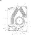
- the air-conditioner 1 may include an indoor heat exchanger 16, a fan 17, and a guide structure forming a discharge flow path 180.
- the air-conditioner 1 may include the indoor heat exchanger 16 disposed inside the case 10.
- the indoor heat exchanger 16 may heat-exchange air and a refrigerant inside the case 10.
- the indoor heat exchanger 16 may heat-exchange air introduced through the intake port 11 and the refrigerant.
- the air that has been heat-exchanged through the indoor heat exchanger 16 may be supplied to the indoor space through the discharge port 12.
- the indoor heat exchanger 16 may heat-exchange an air flow formed by the fan 17 with the refrigerant.
- the indoor heat exchanger 16 may function as an evaporator or a condenser.
- the indoor heat exchanger 16 may function as an evaporator to supply cold air to the indoor space.
- the indoor heat exchanger 16 may function as a condenser to supply warm air to the indoor space.
- the air-conditioner 1 may include a fan 17 disposed inside the case 10.
- the fan 17 may form an air flow flowing from the intake port 11 to the discharge port 12.
- the air flow formed by the fan 17 may be heat-exchanged with the refrigerant in the indoor heat exchanger 16.
- the fan 17 may be disposed adjacent to the indoor heat exchanger 16.
- the fan 17 may be located downstream of the indoor heat exchanger 16 in the air flow direction.
- the present disclosure is not limited thereto, and the fan 17 may be located upstream of the indoor heat exchanger 16 in the air flow direction.
- a discharge flow path 180 may be formed in the case 10 through which the air flow formed by the fan 17 flows.
- the discharge flow path 180 may be located downstream of the fan 17 in the air flow direction.
- the discharge flow path 180 may be located downstream of the indoor heat exchanger 16 in the air flow direction.
- the air flow passing through the indoor heat exchanger 16 or the fan 17 may flow to the discharge port 12 through the discharge flow path 180.
- the discharge flow path 180 may be connected to the discharge port 12.
- the air-conditioner 1 may include a front guide 184 forming the discharge flow path 180.
- the front guide 184 may be disposed inside the case 10.
- the front guide 184 may separate the indoor heat exchanger 16 and the discharge flow path 180.
- the front guide 184 may prevent air that has not passed through the indoor heat exchanger 16 from flowing into the discharge flow path 180.
- the front guide 184 may be disposed below the indoor heat exchanger 16.
- the front guide 184 may be disposed adjacent to the discharge port 12.
- the front guide 184 may extend from the fan 17 toward the discharge port 12.
- the front guide 184 may extend from the fan 17 toward the first discharge port 12a.
- the front guide 184 may extend to be bent. Through this, the discharged air flow may flow smoothly.
- the air-conditioner 1 may include a middle guide 181 spaced apart from the front guide 184.
- the middle guide 181 may be disposed inside the case 10.
- the fan 17 may be disposed between the middle guide 181 and the front guide 184.
- the middle guide 181 may guide the air flow passing through the fan 17 to the discharge flow path 180.
- the middle guide 181 may be spaced rearward from the front guide 184, and the fan 17 may be located between the front guide 184 and the middle guide 181 to form the air flow.
- the middle guide 181 may extend to be bent in a rotation direction of the fan 17.
- the air-conditioner 1 may include a rear guide 182 forming the discharge flow path 180.
- the discharge flow path 180 may be formed between the front guide 184 and the rear guide 182.
- the rear guide 182 may be spaced apart from the front guide 184.
- the rear guide 182 may be spaced rearward from the front guide 184.
- the rear guide 182 may be connected to the middle guide 181.
- the rear guide 182 may extend from the middle guide 181 toward the discharge port 12.
- the rear guide 182 may extend from the middle guide 181 toward a second discharge port (12b, not shown) described below.
- the rear guide 182 may be disposed below the middle guide 181.
- the rear guide 182 may be disposed below the fan 17.
- the rear guide 182 may be disposed adjacent to the discharge port 12.
- the discharge port 12 may include the second discharge port (12b, not shown) open downwardly in the case 10.
- the second discharge port (12b, not shown) may be formed on the lower wall 106 of the case 10.
- the second discharge port (12b, not shown) may be adjacent to the first discharge port 12a.
- the first discharge port 12a may be open forwardly in the front wall 102 of the case 10
- the second discharge port (12b, not shown) may be open downwardly in the lower wall 106 of the case 10.
- the discharged air may be discharged forwardly and downwardly through the first discharge port 12a and the second discharge port (12b, not shown), respectively.
- the discharge vane may include a second discharge vane 15 disposed in the second discharge port (12b, not shown).
- the second discharge vane 15 may open or close the second discharge port (12b, not shown).
- the air-conditioner 1 may include a guide module 30 disposed in the discharge flow path 180.
- the guide module 30 may include a plurality of vanes (see FIG. 5 , 32 and 34).
- the guide module 30 may guide the flow direction of the air flow flowing in the discharge flow path 180.
- the guide module 30 may guide the flow direction of the air flow flowing in the discharge flow path 180 in the left-right direction. Through this, the direction of the air flow discharged into the indoor space may be controlled more precisely.
- the guide module 30 may be coupled to the rear guide 182.
- the guide module 30 may be disposed between the rear guide 182 and the front guide 184.
- the plurality of vanes may move in the left-right direction.
- the guide module 30 may be located downstream of the fan 17 in the air flow direction.
- the guide module 30 may be located between the discharge port 12 and the fan 17 along the air flow path.
- the air-conditioner 1 may include a radar module 40 that detects an occupant in an indoor space.
- the radar module 40 may detect a biosignal of the indoor space.
- the radar module 40 may detect a location of an occupant, the number of occupants, the amount of activity, the movement of the occupant, a respiratory rate of the occupant, a body temperature of the occupant, a vital state of the occupant, a posture of the occupant, etc.
- the air-conditioner 1 may control at least one of wind speed, wind direction, and set temperature based on the detected biosignal result value.
- the radar module 40 may include a radar sensor 44 that detects a biosignal.
- the radar sensor 44 may transmit and/or receive radio waves.
- the radar sensor 44 may be disposed toward an indoor space.
- the radar sensor 44 may detect a biosignal in the indoor space.
- the radar sensor 44 may include a thermopile sensor.
- the radar sensor 44 may use radio waves that penetrate and/or reflect obstacles.
- the radar sensor 44 may detect a biosignal by transmitting and receiving radio waves of a specific Hz. For example, the radar sensor 44 may detect a biosignal in an indoor space using millimeter waves (mm-Wave).
- mm-Wave millimeter waves
- the radar sensor 44 may be disposed inside the case 10.
- the radar sensor 44 may be disposed adjacent to an electrical portion 50.
- the internal space of the case 10 may be divided into a first internal space in which the indoor heat exchanger 16 and the fan 17 are disposed and a second internal space in which the electrical portion 50 is disposed.
- the radar sensor 44 may be disposed in the second internal space.
- the radar sensor 44 may be disposed between the indoor heat exchanger 16 and the electrical portion 50.
- the radar sensor 44 may be disposed on the front surface of the case 10.
- the radar sensor 44 may be disposed on the front wall 102 of the case 10.
- the radar sensor 44 may be disposed on a rear surface of the front wall 102.
- the radar sensor 44 may use radio waves that penetrate the front wall 102.
- the radar sensor 44 may detect a biosignal of an indoor space by transmitting and/or receiving a radio wave that penetrates the front wall 102.
- the radar sensor 44 may be located to face the indoor space.
- the radar sensor 44 may be disposed forwardly.
- the radar sensor 44 may be located so as to face the front wall 102.
- the air-conditioner 1 may include the electrical portion 50.
- the electrical portion 50 may be located in the second internal space of the case 10.
- the electrical portion 50 may be located apart from the indoor heat exchanger 16 and/or the fan 17.
- the display 14 may be located in front of the electrical portion 50.
- the display 14 may be located on the rear side of the front wall 102.
- the display 14 may be located between the electrical portion 50 and the front wall 102.
- the air-conditioner 1 may include a drain pan 19 that collects condensate occurring in the indoor heat exchanger 16.
- the drain pan 19 may be disposed inside the case 10.
- the drain pan 19 may be disposed below the indoor heat exchanger 16. Through this, condensate occurring in the indoor heat exchanger 16 may fall to the drain pan 19.
- the drain pan 19 may be elongated in the length direction of the indoor heat exchanger 16.
- the air-conditioner 1 may include a chassis 60 disposed inside the case 10.
- the chassis 60 may be coupled to the case 10.
- the indoor heat exchanger 16 may be coupled to the chassis 60.
- the fan 17 may be coupled to the chassis 60.
- the chassis 60 may include a fan holder 61 coupled to the fan 17.
- the fan holder 61 may include a first fan holder 61a and a second fan holder 61b spaced apart from each other in the length direction of the fan 17.
- the first internal space and the second internal space of the case 10 may be divided based on the second fan holder 61b. That is, based on the second fan holder 61b, a first internal space in which the fan 17 and the indoor heat exchanger 16 are disposed may be formed on one side, and a second internal space in which the electric portion 50 is disposed may be formed on the other side.
- the rear guide 182 may be disposed in the first internal space.
- the rear guide 182 may be coupled to the chassis 60.
- the guide module 30 may be disposed in the first internal space.
- the guide module 30 may be coupled to the rear guide 182.
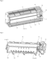
- the guide module 30 will be described with reference to FIG. 5 .
- the guide module 30 may include a plurality of vanes 32 and 34 arranged in the discharge flow path 180.
- the plurality of vanes 32 and 34 may be arranged in a row.
- the plurality of vanes 32 and 34 may be spaced apart from each other.
- the plurality of vanes 32 and 34 may be arranged in a direction intersecting the flow direction of the air flow toward the discharge port 12. For example, the air flow may flow in an up-down direction, and the plurality of vanes 32 and 34 may be disposed in the left-right direction.
- the vanes 32 and 34 may include a pair of first vanes 32 spaced apart from each other.
- the pair of first vanes 32 may be disposed at the edge of the guide module 30.
- the pair of first vanes 32 may be disposed close to an inner wall forming the discharge flow path 180.
- the pair of first vanes 32 may be disposed at one end and the other end of the guide module 30, respectively, in the length direction.
- the pair of first vanes 32 may be disposed at one end and the other end in a direction in which the plurality of vanes 32 and 34 are arranged, respectively.
- the first vane 32 may form the edge of the plurality of vanes 32 and 34.
- the plurality of vanes 32 and 34 may include a plurality of second vanes 34 arranged between the pair of first vanes 32.
- the plurality of second vanes 34 may be arranged in a direction in which the pair of first vanes 32 are spaced apart from each other. That is, the direction in which the plurality of second vanes 34 are arranged and the direction in which the pair of first vanes 32 are spaced apart from each other may be parallel.
- the guide module 30 may include a coupling panel 31 to which the plurality of vanes 32 and 34 are coupled.
- the coupling panel 31 may be elongated.
- the coupling panel 31 may be coupled to the discharge flow path 180.
- the pair of first vanes 32 may be coupled to one end and the other end of the coupling panel 31, respectively.
- the plurality of second vanes 34 may be coupled to the coupling panel 31 between the pair of first vanes 32.
- the guide module 30 may include a link 36 coupled to the plurality of vanes 32 and 34.
- the link 36 may be elongated.
- the link 36 may include a link panel 364 and a link stick 362 elongated from the link panel 364.
- a width of the link panel 364 may be greater than a width of the link stick 362.
- a length of the link panel 364 may be shorter than a length of the link stick 362.
- the pair of first vanes 32 may be respectively coupled to one end and the other end of the link stick 362 in the length direction.
- a plurality of second vanes 34 may be coupled to the link stick 362 and the link panel 364.
- the plurality of vanes 32 and 34 may move integrally with the link 36. For example, as the link 36 moves in the left-right direction, the plurality of vanes 32 and 34 may move in the left-right direction. Accordingly, the flow direction of the air flow flowing through the discharge flow path 180 may be adjusted.
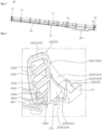
- the pair of first vanes 32 will be described with reference to FIG. 6 .
- the first vane 32 may include a fixing member 322 coupled to the coupling panel 31.
- the fixing member 322 may be fixed to the coupling panel 31.
- the width of the fixed portion 322 may increase in the flow direction of the discharged air flow.
- the first vane 32 may include a movable portion 326 to which a link 36 is coupled.
- the movable portion 326 may be separated from the fixed portion 322.
- the movable portion 326 may be movable.
- the movable portion 326 may be movable in a direction intersecting the flow direction of the discharged air flow.
- the movable portion 326 may be movable in the left-right direction by the link 36 coupled thereto.
- the width of the movable portion 326 may be greater than the width of the fixed portion 322.
- the first vane 32 may include a connecting portion 324 connecting the movable portion 326 to the fixed portion 322.
- the connecting portion 324 may be located between the movable portion 326 and the fixed portion 322.
- the width of the connecting portion 324 may gradually increase from the fixed portion 322 to the movable portion 326.
- the thickness of the connecting portion 324 may be thinner than the thickness of the fixed portion 322.
- the thickness of the connecting portion 324 may be thinner than the thickness of the movable portion 326. Through this, the flexibility of the connecting portion 324 may be greater than the flexibility of the fixed portion 322 or the movable portion 326.
- the connecting portion 324 may be connected to the moving movable portion 326 and may be bent.
- the connecting portion 324 may be bent according to the movable portion 326 moving in the left-right direction.
- the connecting portion 324 may include a first connecting portion 3242 connecting the movable portion 326 to the fixed portion 322 and a second connecting portion 3244 located between the movable portion 326 and the fixed portion 322.
- the second connecting portion 3244 may extend from the movable portion 326.
- the second connecting portion 3244 may extend from the movable portion 326 toward the fixed portion 322 and may be spaced apart from the fixed portion 322. That is, the second connecting portion 3244 may not be connected to the fixed portion 322. Accordingly, the second connecting portion 3244 may move integrally with the movement of the movable portion 326.
- the second connecting portion 3244 may include a curved portion 3245 whose edge facing the fixed portion 322 is formed to be curved. That is, the edge of the second connecting portion 3244 facing the fixed portion 322 may be formed in a curved shape. Accordingly, the discharged air flow may smoothly pass through the second connecting portion 3244, thereby reducing noise.
- the width of the connecting portion 324 may increase from the fixed portion 322 to the movable portion 326.
- the width of the second connecting portion 3244 may increase from the fixed portion 322 to the movable portion 326.
- the first connecting portion 3242 and the second connecting portion 3244 may be spaced apart from each other.
- the connecting portion 324 may include a slit 3240 formed between the first connecting portion 3242 and the second connecting portion 3244.
- the slit 3240 may be elongated.
- the slit 3240 may extend from a gap between the second connecting portion 3244 and the fixed portion 322.
- the slit 3240 may be formed between the first connecting portion 3242 and the second connecting portion 3244, so that the first connecting portion 3242 that moves dependently on the fixed portion 322 and the second connecting portion 3244 that moves freely may move independently without interfering with each other.
- the movable portion 326 may include a first movable portion 3261 directly connected to the connecting portion and a second movable portion 3262 coupled to the link 36.
- the first movable portion 3261 may connect the second movable portion 3262 to the connecting portion 324.
- the first connecting portion 3242 and the second connecting portion 3244 may be connected to the first movable portion 3261.
- the first connecting portion 3242 may connect the first movable portion 3261 to the fixed portion 322.
- the thickness of the first movable portion 3261 may gradually increase from the first connecting portion 3242 to the second movable portion 3262. Due to the change in the thickness of the first movable portion 3261, a step may not be formed between the connecting portion 324 and the movable portion 326. Accordingly, the air flow flowing along the vanes 32 and 34 may flow smoothly.
- the first vane 32 may include a communication hole 3260 formed in the movable portion 326.
- the communication hole 3260 may be a through-hole formed to penetrate the vanes 32 and 34.
- the communication hole 3260 may be formed in a direction intersecting the flow direction of the discharged air flow.
- the communication hole 3260 may be formed in a direction in which the plurality of vanes 32 and 34 are arranged. Accordingly, the air flow flowing along the first vane 32 may flow through the first vane 32.
- the communication hole 3260 may include a plurality of communication holes 3260 formed in the movable portion 326.
- the plurality of communication holes 3260 may be arranged in a direction intersecting the flow direction of the discharged air flow.
- the plurality of communication holes 3260 may be arranged in a direction intersecting the direction in which the plurality of vanes 32 and 34 are arranged.
- the plurality of communication holes 3260 may be arranged in a width direction of the movable portion 326.
- the plurality of communication holes 3260 may be disposed in the up-down direction.
- the communication hole 3260 may be elongated.
- the communication hole 3260 may be elongated in a direction parallel to the flow direction of the discharged air flow.
- the communication hole 3260 may be elongated in a direction intersecting the width direction of the movable portion 326.
- the communication hole 3260 may be elongated in the up-down direction or a front-rear direction. Through this, the air flow flowing through the discharge flow path may smoothly pass through the communication hole 3260 and flow.
- the movable portion 326 may include a brace 3264 formed between a plurality of communication holes 3260.
- the brace 3264 may partition the plurality of communication holes 3260.
- the brace 3264 may be elongated.
- the brace 3264 may extend in a direction parallel to the flow direction of the discharged air flow.
- the brace 3264 may be elongated in the up-down direction or the left-right direction.
- the brace 3264 may include a plurality of braces 3264 formed between the plurality of communication holes 3260.
- the vanes 32 and 34 may include a coupling slot 3263 in which the link 36 is disposed.
- the coupling slot 3263 may be formed in the movable portion 326.
- the coupling slot 3263 may be a through-hole formed in the vanes 32 and 34.
- the coupling slot 3263 may be formed in a direction intersecting the flow direction of the discharged air flow.
- the coupling slot 3263 may be elongated in a direction parallel to the flow direction of the discharged air flow. Through this, the discharged air flow may also flow through the vanes 32 and 34 also through the coupling slot 3263.
- the coupling slot 3263 may be disposed in a row with the plurality of communication holes 3260.
- the coupling slot 3263 and the plurality of communication holes 3260 may be formed in a row in the up-down direction or the front-rear direction on the movable portion 326.
- the coupling panel 31 may include a hook 312 coupled to the discharge flow path 180.
- the coupling panel 31 may be hook-coupled to the rear guide 182 forming the discharge flow path 180.
- the second vane 34 will be described with reference to FIG. 7 .
- the second vane 34 may include a fixed portion 342 coupled to the coupling panel 31.
- the fixed portion 342 may be fixed to the coupling panel 31.
- the width of the fixed portion 342 may increase in the flow direction of the discharged air flow.
- the second vane 34 may include a movable portion 346 to which the link 36 is coupled.
- the movable portion 346 may be separated from the fixed portion 342.
- the movable portion 346 is movable.
- the movable portion 346 may be movable in a direction intersecting the flow direction of the discharged air flow.
- the movable portion 346 may be movable in the left-right direction by the coupled link 36.
- the width of the movable portion 346 may be greater than the width of the fixed portion 342.
- the second vane 34 may include a connecting portion 344 connecting the movable portion 346 to the fixed portion 342.
- the connecting portion 344 may be located between the movable portion 346 and the fixed portion 342.
- the width of the connecting portion 344 may gradually increase from the fixed portion 342 to the movable portion 346.
- the thickness of the connecting portion 344 may be thinner than the thickness of the fixed portion 342.
- the thickness of the connecting portion 344 may be thinner than the thickness of the movable portion 346.
- the flexibility of the connecting portion 344 may be greater than the flexibility of the fixed portion 342 or the movable portion 346.
- the connecting portion 344 may be connected to the moving movable portion 346 and may be bent.
- the connecting portion 344 may be bent according to the movable portion 346 moving in the left-right direction.
- the connecting portion 344 may include a first connecting portion 3442 connecting the movable portion 346 to the fixed portion 342 and a second connecting portion 3444 located between the movable portion 346 and the fixed portion 342.
- the second connecting portion 3444 may extend from the movable portion 346.
- the second connecting portion 3444 may be connected from the movable portion 346 toward the fixed portion 342 and may be spaced apart from the fixed portion 342. That is, the second connecting portion 3444 may not be connected to the fixed portion 342. Accordingly, the second connecting portion 3444 may move more freely along with the moving movable portion 346.
- the second connecting portion 3444 may include a curved portion 3245 whose edge facing the fixed portion 342 is formed to be curved. That is, the edge of the second connecting portion 3444 facing the fixed portion 342 may be formed in a curved shape. Accordingly, the discharged air flow may smoothly pass through the second connecting portion 3444 and noise that occurs may be reduced.
- the width of the connecting portion 344 may increase from the fixed portion 342 to the movable portion 346.
- the width of the second connecting portion 3444 may increase from the fixed portion 342 to the movable portion 346.
- the first connecting portion 3442 and the second connecting portion 3444 may be spaced apart from each other.
- the connecting portion 344 may include a slit 3440 formed between the first connecting portion 3442 and the second connecting portion 3444.
- the slit 3440 may be elongated.
- the slit 3440 may extend from a gap between the second connecting portion 3444 and the fixed portion 342.
- the slit 3440 may be formed between the first connecting portion 3442 and the second connecting portion 3444, so that the first connecting portion 3442 that moves dependently on the fixed portion 342 and the second connecting portion 3444 that moves freely may move independently without interfering with each other.
- the movable portion 3466 may include a first movable portion 3461 that is directly connected to the connecting portion and a second movable portion 3462 to which the link 36 is coupled.
- the first movable portion 3461 may connect the second movable portion 3462 to the connecting portion 344.
- the first connecting portion 3442 and the second connecting portion 3444 may be connected to the first movable portion 3461.
- the first connecting portion 3442 may connect the first movable portion 3461 to the fixed portion 342.
- the thickness of the first movable portion 3461 may gradually increase from the first connecting portion 3442 to the second movable portion 3462. Due to the change in the thickness of the first movable portion 3461, a step may not be formed between the connecting portion 344 and the movable portion 346. Accordingly, the air flow flowing along the vanes 32 and 34 may flow smoothly.
- the second vane 34 may include a coupling slot 3463 in which the link 36 is disposed.
- the coupling slot 3463 may be formed in the movable portion 346.
- the coupling slot 3463 may be a through-hole formed in the vanes 32 and 34.
- the coupling slot 3463 may be formed in a direction intersecting the flow direction of the discharged air flow.
- the coupling slot 3463 may be elongated in a direction parallel to the flow direction of the discharged air flow. Through this, the discharged air flow may also flow through the vanes 32 and 34 also through the coupling slot 3463.
- the coupling slot 3463 may be disposed in a row with a plurality of communication holes 3260.
- the coupling slot 3463 and the plurality of communication holes 3260 may be formed in a row in the up-down direction or the front-rear direction in the movable portion 346.
- the vanes 32 and 34 may include a coupling pillar 3464 to which the link 36 is coupled.
- the coupling pillar 3464 may be formed in the coupling slots 3263 and 3463.
- the coupling pillar 3464 may extend in the width direction of the vanes 32 and 34.
- the movable portions 326 and 346 may include the coupling pillar 3464.
- the vanes 32 and 34 may include a support member 3465 extending from the coupling pillar 3464.
- the support member 3465 may support the vanes 32 and 34.
- the support member 3465 may support the movable portions 326 and 346.
- the support member 3465 may slide as the movable portions 326 and 346 move.
- the support member 3465 may be formed in a cylindrical shape. The radius of the support member 3465 may be greater than the radius of the coupling pillar 3464.
- the link 36 may include a coupling recess 363 coupled to the coupling pillar 3464.
- the link stick 362 may include the coupling recess 363.
- the coupling pillar 3464 may be inserted into the coupling recess 363.
- the coupling pillar 3464 may be rotatably coupled to the coupling recess 363. Through this, the coupling pillar 3464 may move while being coupled to the coupling recess 363.
- the thickness of the vanes 32 and 34 is described with reference to FIG. 9 .
- the thickness of the vanes 32 and 34 may change in the flow direction of the discharged air flow.
- the thickness of the connecting portions 324 and 344 may be thinner than the thickness of the fixed portions 322 and 342.
- the thickness of the connecting portions 324 and 344 may be thinner than the thickness of the movable portions 326 and 346. Through this, the flexibility of the connecting portions 324 and 344 may be improved.
- the thickness of the fixed portions 322 and 342 may be thicker than the thickness of the connecting portions 324 and 344. Since the thickness of the fixed portions 322 and 342 is thicker than the thickness of the connecting portions 324 and 344, fixing force fixed to the coupling panel 31 may be improved.
- the thickness of the movable portions 326 and 346 may be thicker than the thickness of the connecting portions 324 and 344. Since the thickness of the movable portions 326 and 346 is thicker than the thickness of the connecting portions 324 and 344, the rigidity of the movable portions 326 and 346 moved by the link 36 may be improved.
- One surfaces 32b and 34b of the vanes 32 and 34 may be formed flat.
- One surface 32b of the first vane 32 may be formed flat.
- One surface 34b of the second vane 34 may be formed flat.
- the other surfaces 32a and 34a of the vanes 32 and 34 may be recessed.
- the other surfaces 32a and 34a of one region of the vanes 32 and 34 corresponding to the connecting portions 324 and 344 may be recessed. Through this, the thickness between one surfaces 32b and 34b and the other surfaces 32a and 34a of the vanes 32 and 34 may be reduced.
- the chassis 60 to which the guide module 30 is coupled will be described with reference to FIG. 10 .
- the chassis 60 may form the discharge flow path 180.
- the guide module 30 may be coupled to the chassis 60.
- the guide module 30 may be coupled to the rear guide 182 forming the discharge flow path 180.
- the rear guide 182 may include a recessed portion 632 to which the guide module 30 is coupled.
- the recessed portion 632 may be recessed from a surface of the rear guide 182.
- the surface of the rear guide 182 may refer to one surface of the rear guide 182 forming the discharge flow path 180.
- the coupling panel 31 of the guide module 30 may be coupled to the recessed portion 632.
- the surface of the coupling panel 31 may be located parallel to the surface of the rear guide 182.
- the surface of the coupling panel 31 may be referred to as one surface to which the plurality of vanes 32 and 34 are coupled.
- the surface of the coupling panel 31 and the surface of the rear guide 182 may be located on a continuous virtual surface.
- the surface of the coupling panel 31 and the surface of the rear guide 182 may form a continuous surface.
- the rear guide 182 may include a driving recess 634.
- the guide module 30 may receive driving force through the driving recess 634.
- a driving unit (not shown) that drives the guide module 30 may be disposed on a rear surface of the rear guide 182.
- the driving unit (not shown) may drive the link 36 of the guide module 30 through the driving recess 634.
- the guide module 30 will be described with reference to FIG. 11 .
- the guide module 30 may include a driving shaft 365 that receives driving force.
- the driving shaft 365 may be formed in the link 36.
- the driving shaft 365 may be formed in the link panel 364 of the link 36.
- the driving shaft 365 may be connected to the driving unit (not shown) through the driving recess 634 of the rear guide 182.
- the power of the driving unit (not shown) may drive the driving shaft 365.
- the plurality of vanes 32 and 34 connected to the link 36 may move integrally.
- the second discharge vane 15 of the air-conditioner 1 will be described with reference to FIG. 12 .
- the first discharge port 12a may be open forwardly in the case 10.
- the first discharge port 12a may be formed on the front surface of the case 10.
- the first discharge port 12a may be elongated in a lower portion of the front wall 102 of the case 10.
- the second discharge port (12b, not shown) may be open downwardly in the case 10.
- the second discharge port (12b, not shown) may be formed on a lower surface of the case 10.
- the second discharge port (12b, not shown) may be adjacent to the first discharge port 12a.
- the second discharge port (12b, not shown) may be elongated in a lower front portion of the case 10.
- the first discharge port 12a and the second discharge port (12b, not shown) may be adjacent to one corner of the case 10.
- the first discharge port 12a and the second discharge port (12b, not shown) may be adjacent to the lower corner of the front wall 102.
- the lower corner of the front wall 102 may correspond to the front corner of the lower surface of the case 10.
- the first discharge port 12a may be opened.
- the first discharge port 12a may not be closed.
- the second discharge port (12b, not shown) may be opened and closed.
- the first discharge port 12a may be opened at all times, and the second discharge port (12b, not shown) may be opened when the air-conditioner 1 is in operation and closed when the air-conditioner 1 is stopped.
- the second discharge port (12b, not shown) may be closed when the air-conditioner 1 is in operation.
- the air-conditioner 1 may include a lower cover 106 coupled to a lower portion of the case 10.
- the lower cover 106 may be detachably coupled to the case 10.
- the lower cover 106 may form a lower surface of the case 10.
- the second discharge vane 15 may be disposed in the second discharge port (12b, not shown).
- the second discharge vane 15 may be coupled to the case 10.
- the second discharge vane 15 may be coupled to the lower cover 106.
- the second discharge vane 15 may open or close the second discharge port (12b, not shown). For example, when an operation signal is input to the air-conditioner 1, the second discharge vane 15 may be opened, and when an operation end signal is input to the air-conditioner 1, the second discharge vane 15 may be closed. However, the present disclosure is not limited thereto, and the second discharge vane 15 may be closed when the air-conditioner 1 is in operation.
- the second discharge vane 15 that closes the second discharge port (12b, not shown) may be aligned parallel to the lower cover 106.
- a lower surface of the second discharge vane 15 that closes the second discharge port (12b, not shown) may be aligned parallel to the lower surface of the lower cover 106.
- the structure of the second discharge vane 15 will be described with reference to FIGS. 13 and 14 .
- the second discharge vane 15 may include a guide panel 152.
- the guide panel 152 may form one surface of the second discharge vane 15.
- the guide panel 152 may guide the discharged air flow.
- the guide panel 152 may be disposed on the inside of the case 10.
- the guide panel 152 may be disposed obliquely with respect to the second discharge port (12b, not shown).
- the guide panel 152 may open or close the second discharge port (12b, not shown).
- the guide panel 152 may be elongated.
- the guide panel 152 may include one surface that is elongated.
- the guide panel 152 may have an uneven portion formed on a surface thereof.
- the uneven portion may be elongated in the length direction of the guide panel 152.
- the guide panel 152 may have a width formed in a direction intersecting the length direction.
- the uneven portion may be repeated in the width direction of the guide panel 152.
- the guide panel 152 may include a pair of longer sides LS1 and LS2 and a pair of shorter sides SS1 and SS2.
- the uneven portion may be elongated in a direction parallel to the pair of longer sides LS 1 and LS2.
- the uneven portion may be arranged in the length direction of the pair of shorter sides SS1 and SS2.
- a region of the guide panel 152 in which the uneven portion is formed may be spaced apart from the pair of longer sides LS 1 and LS2.
- a region of the guide panel 152 in which the uneven portion is formed may be spaced apart from the pair of shorter sides SS1 and SS2.
- the second discharge vane 15 may include a coupling flange 1522 coupled to the case 10.
- the coupling flange 1522 may be formed on the guide panel 152.
- the coupling flange 1522 may protrude from the guide panel 152.
- the coupling flange 1522 may be formed at each end of the second discharge vane 15 in the length direction.
- a pair of coupling flanges 1522 may be formed at the left and right ends of the second discharge vane 15, respectively.
- the structure of the second discharge vane 15 will be described with reference to FIG. 15 .
- the second discharge vane 15 may include a base panel 154.
- the base panel 154 may form the other surface of the second discharge vane 15.
- the base panel 154 may open or close the second discharge port (12b, not shown).
- the base panel 154 may be disposed obliquely with respect to the second discharge port (12b, not shown).
- the base panel 154 may be disposed on an outer surface of the case 10.
- the base panel 154 may be disposed parallel to the lower cover 106.
- the surface of the base panel 154 may be formed flat. For example, a lower surface of the base panel 154 may be formed flat.
- the guide panel 152 may be coupled to the base panel 154.
- the guide panel 152 may form an upper portion of the second discharge vane 15, and the base panel 154 may form a lower portion of the second discharge vane 15.
- the guide panel 152 may form an upper surface of the second discharge vane 15, and the base panel 154 may form a lower surface of the second discharge vane 15.
- the second discharge vane 15 may include an accommodating space 150.
- the accommodating space 150 may be formed between the guide panel 152 and the base panel 154.
- a rear surface of the guide panel 152 and a rear surface of the base panel 154 may form an outer circumferential surface of the accommodating space 150.
- the rear surface of the guide panel 152 may be a lower surface of the guide panel 152.
- the rear surface of the base panel 154 may be an upper surface of the base panel 154.
- the second discharge vane 15 may include an insulating member 156 disposed in the accommodating space 150.
- the insulating member 156 may be disposed between the guide panel 152 and the base panel 154.
- the insulating member 156 may be coupled to at least one of the guide panel 152 and the base panel 154.
- the insulating member 156 may be bonded to at least one of the guide panel 152 and the base panel 154.
- the insulating member 156 and the guide panel 152 may be formed of different materials.
- the insulating member 156 and the base panel 154 may be formed of different materials.
- the insulating member 156 may be formed of a polyethylene (PE) material.
- the second discharge vane 15 may include a supporter 1528 disposed between the guide panel 152 and the base panel 154.
- the supporter 1528 may be disposed in the accommodating space.
- the supporter 1528 may be elongated in the length direction of the second discharge vane 15.
- the supporter 1528 may protrude from the guide panel 152.
- the supporter 1528 may protrude from the rear surface of the guide panel 152 toward the base panel 154.
- the supporter 1528 may support the guide panel 152.
- the supporter 1528 may separate the guide panel 152 and the base panel 154 from each other.
- the supporter 1528 may divide the accommodating space 150 into a first accommodating space 1501 and a second accommodating space 1502.
- the first accommodating space 1501 may be located in front of the supporter 1528.
- the second accommodating space 1502 may be located at the rear of the supporter 1528.
- the volume of the second accommodating space 1502 may be greater than the volume of the first accommodating space 1501.
- the insulating member 156 may include a first insulating member 1561 disposed in the first accommodating space 1501 and a second insulating member 1562 disposed in the second accommodating space.
- the first insulating member 1561 and the second insulating member 1562 may be formed of different materials.
- the first insulating member 1561 may be formed of a polyethylene (PE) material
- the second insulating member 1562 may be formed of a polyurethane (PU) material.
- PE polyethylene
- PU polyurethane
- the guide panel 152 may include an uneven portion formed on a surface thereof.
- the surface of the guide panel 152 may be an upper surface of the guide panel 152.
- the guide panel 152 may include a first groove 1524 recessed from the surface.
- the guide panel 152 may include a first rib 1526 protruding from the surface.
- the first groove 1524 and the first rib 1526 may be arranged alternately.
- the first groove 1524 and the first rib 1526 may be elongated in the length direction of the guide panel 152.
- the first groove 1524 and the first rib 1526 may be arranged alternately in the width direction of the guide panel 152.
- the base panel 154 may include a protrusion formed on a rear surface thereof.
- the rear surface of the base panel 154 may be an upper surface of the base panel 154.
- the base panel 154 may include a second groove 1544 recessed from the rear surface.
- the base panel 154 may include a second rib 1546 protruding from the rear surface.
- the second groove 1544 and the second rib 1546 may be arranged alternately.
- the second groove 1544 and the second rib 1546 may be elongated in the length direction of the base panel 154.
- the second groove 1544 and the second rib 1546 may be arranged alternately in the width direction of the base panel 154.
- the guide panel 152 may have a height lowered toward the longer sides LS1 and LS2.
- the guide panel 152 may have a height lowered toward the first longer side LS 1 and the second longer side LS2.
- the guide panel 152 may have a height lowered toward a rear end.
- the guide panel 152 may include a first inclined portion 1523 that is inclined downwardly toward the rear.
- the first inclined portion 1523 may be connected to a flat portion 1521 of the guide panel 152.
- a first insulating member 1561 may be disposed between the first inclined portion 1523 and the base panel 154.
- the guide panel 152 may have a height lowered toward a front end.
- the guide panel 152 may include a second inclined portion 1525 that is inclined downwardly toward the front.
- the second inclined portion 1525 may be connected to the flat portion 1521 of the guide panel 152.
- a second accommodating space 1502 may be formed between the second inclined portion 1525 and the base panel 154.
- a second insulating member 1562 may be disposed between the second inclined portion 1525 and the base panel 154.
- the guide panel 152 may include a flat portion 1521 connected to the first inclined portion 1523 and/or the second inclined portion 1525.
- the flat portion 1521 may be located between the first inclined portion 1523 and the second inclined portion 1525.
- the flat portion 1521 may be spaced apart from the base panel 154.
- the uneven portion of the guide panel 152 may be formed on the flat portion 1521.
- the uneven portion of the guide panel 152 may be formed on the first inclined portion 1523 and/or the second inclined portion 1525.
- the uneven portion of the guide panel 152 may be formed from an upper surface of the first inclined portion 1523 to an upper surface of the second inclined portion 1525 through to an upper surface of the flat portion 1521.
- the insulating member 156 may be disposed on at least one of the first inclined portion 1523 and the second inclined portion 1525.
- the second insulating member 1562 may be disposed on the inner side of the second inclined portion 1525.
- the second insulating member 1562 may be disposed in the second accommodating space 1502 formed between the second inclined portion 1525 and the base panel 154.
- the second insulating member 1562 may be disposed on the inner side of the first inclined portion 1523.
- the second insulating member 1562 may be disposed between the first inclined portion 1523 and the base panel 154.
- the first insulating member 1561 may be disposed between the flat portion 1521 and the base panel 154, and the second insulating member 1562 may be disposed in a space formed between the first inclined portion 1523 and the base panel 154 and a space formed between the second inclined portion 1525 and the base panel 154.
- the second discharge vane 15 may be disposed in the second discharge port (12b, not shown).
- the second discharge vane 15 may open or close the second discharge port (12b, not shown).
- the second discharge vane 15 may be operated in the second discharge port (12b, not shown).
- the second discharge vane 15 that closes the second discharge port (12b, not shown) may be disposed parallel to the lower surface of the case 10.
- the base panel 154 that closes the second discharge port (12b, not shown) may be disposed parallel to the lower cover 106.
- the second discharge vane 15 that opens the second discharge port (12b, not shown) may be disposed obliquely with respect to the lower surface of the case 10.
- the discharge flow path 180 may include a first discharge flow path 1801 formed between the rear guide 182 and the front guide 184.
- the discharge flow path 180 may include a second discharge flow path 1802 formed between the first discharge flow path 1801 and the discharge port 12.
- the second discharge flow path 1802 may be formed between the second discharge vane 15 and the front guide 184.
- the rear guide 182 may extend to be curved from the fan 17 toward the second discharge vane 15. A downstream edge of the rear guide 182 may be adjacent to the second discharge vane 15. A downstream end portion of the rear guide 182 may extend toward the first inclined portion 1523 of the second discharge vane 15. The rear guide 182 may guide the air flow flowing through the first discharge flow path 1801 to the first inclined portion 1523 and the flat portion 1521. The second discharge guide 122 may guide the air flow flowing through the second discharge flow path 1802 to the first discharge port 12a.
- the air-conditioner 1 may include the discharge guide 122 disposed between the first discharge port 12a and the second discharge port (12b, not shown).
- the discharge guide 122 may be disposed at the corner of the case 10 in which the first discharge port 12a and the second discharge port (12b, not shown) are formed.
- the discharge guide 122 may be disposed on the inner surface of the lower corner of the front wall 102.
- the discharge guide 122 may be bent.
- the discharge guide 122 may be formed to be curved.
- the discharge guide 122 may include a first guide surface 1222 forming the first discharge port 12a.
- the discharge guide 122 may include a second guide surface 1224 forming the second discharge port (12b, not shown).
- the first guide surface 1222 may be formed to be inclined.
- the first guide surface 1222 may be inclined upwardly toward the front.
- the first guide surface 1222 may face the first discharge vane 13.
- the first guide surface 1222 may be located below the first discharge vane 13.
- the first guide surface 1222 may guide the air flow flowing through the second discharge flow path 1802 to the first discharge port 12a.
- the second guide surface 1224 may be formed to be inclined.
- the second guide surface 1224 may be inclined downwardly toward the front.
- the second guide surface 1224 may face the second discharge vane 15.
- the second guide surface 1224 may face the second inclined portion 1525.
- the second guide surface 1224 may be located in front of the second discharge vane 15.
- the second guide surface 1224 may guide the air flow flowing through the second discharge flow path 1802 to the second discharge port (12b, not shown).
- the first guide surface 1222 and the second guide surface 1224 may be connected in a curved manner.
- the connecting portion at which the first guide surface 1222 and the second guide surface 1224 are connected may be rounded.
- the closed second discharge vane 15 may be adjacent to the discharge guide 122. When the second discharge vane 15 is closed, the gap from the discharge guide 122 may be narrowed.
- the second inclined portion 1525 of the second discharge vane 15 may face the second guide surface 1224.
- the second inclined portion 1525 may be adjacent to the second guide surface 1224.
- the second inclined portion 1525 may be disposed parallel to the second guide surface 1224.
- the rear guide 182 may guide the air flow flowing in the first discharge flow path 1801 to the second discharge vane 15.
- the second discharge vane 15 may guide the air flow flowing in the second discharge flow path 1802 to the first guide surface 1222. Through this, the closed second discharge vane 15 may guide the air flow flowing through the discharge flow path 180 to the first discharge port 12a.
- the opened second discharge vane 15 may be separated from the discharge guide 122.
- the gap from the discharge guide 122 may increase.
- the second inclined portion 1525 of the second discharge vane 15 may be separated from the second guide surface 1224.
- the air flow flowing through the second discharge flow path 1802 may be discharged to the second discharge port (12b, not shown) through the gap between the second guide surface 1224 of the discharge guide 122 and the second discharge vane 15.
- the opened second discharge vane 15 may control a wind direction of the air flow discharged through the second discharge port (12b, not shown).
- an air-conditioner includes: a case including an intake port and a discharge port; a fan disposed inside the case and forming an air flow; an indoor heat exchanger heat-exchanging air inside the case with a refrigerant; and a guide module disposed downstream of the fan and guiding the air flow flowing to the discharge port, wherein the guide module includes a plurality of vanes arranged in a row in a discharge flow path formed between the discharge port and the fan, the plurality of vanes include a pair of first vanes spaced apart from each other; and a plurality of second vanes arranged between the pair of first vanes, and the pair of first vanes includes a communication hole formed in a penetrating manner.
- the communication hole may include a plurality of communication holes arranged in a direction intersecting a flow direction of the air flow flowing through the discharge flow path.
- the plurality of communication holes may be elongated in a direction parallel to the flow direction of the air flow flowing through the discharge flow path.
- a width of the plurality of communication holes intersecting a length direction may be greater than a spacing between the plurality of communication holes.
- the plurality of vanes may include: a fixed portion fixed to the discharge flow path; a movable portion moving in a direction intersecting the flow direction of the air flow flowing through the discharge flow path; and a connecting portion connecting the fixed portion to the movable portion.
- the communication hole may be formed in the movable portion of the pair of first vanes.
- a thickness of the connecting portion may be thinner than a thickness of the movable portion.
- the guide module may include a link connected to the plurality of vanes and moving in a direction intersecting the flow direction of the air flow flowing through the discharge flow path.
- the movable portion may include a coupling slot in which the link is disposed.
- the coupling slot may be elongated in a direction parallel to the flow direction of the air flow flowing through the discharge flow path.
- the communication hole may include a plurality of communication holes arranged in a direction intersecting the flow direction of the air flow flowing through the discharge flow path, and the coupling slot may be disposed in a row with the plurality of communication holes.
- the movable portion may include: a coupling pillar formed in the coupling slot, and the link may include: a coupling recess coupled to the coupling pillar.
- a thickness of the fixed portion may be thicker than a thickness of the connecting portion.
- the connecting portion may be bent as the movable portion moves.
- the connecting portion may include: a first connecting portion connecting the movable portion to the fixed portion; and a second connecting portion extending from the movable portion toward the fixed portion and spaced apart from the fixed portion.
- the connecting portion may include: a slit formed between the first connecting portion and the second connecting portion.
- an edge of the second connecting portion facing the fixed portion may be formed to be curved.
- a component A described in a specific embodiment and/or drawing may be combined with a component B described in another embodiment and/or drawing. That is, it means that, even if the combination of the components is not directly described, the combination is possible except for a case where the combination is described as impossible.
Landscapes
- Engineering & Computer Science (AREA)
- Chemical & Material Sciences (AREA)
- Combustion & Propulsion (AREA)
- Mechanical Engineering (AREA)
- General Engineering & Computer Science (AREA)
- Physics & Mathematics (AREA)
- Thermal Sciences (AREA)
- Air-Flow Control Members (AREA)
Applications Claiming Priority (1)
| Application Number | Priority Date | Filing Date | Title |
|---|---|---|---|
| KR1020230169991A KR20250081540A (ko) | 2023-11-29 | 2023-11-29 | 공기조화기 |
Publications (1)
| Publication Number | Publication Date |
|---|---|
| EP4563902A1 true EP4563902A1 (de) | 2025-06-04 |
Family
ID=93741787
Family Applications (1)
| Application Number | Title | Priority Date | Filing Date |
|---|---|---|---|
| EP24216243.6A Pending EP4563902A1 (de) | 2023-11-29 | 2024-11-28 | Klimaanlage |
Country Status (4)
| Country | Link |
|---|---|
| US (1) | US20250172318A1 (de) |
| EP (1) | EP4563902A1 (de) |
| KR (1) | KR20250081540A (de) |
| CN (1) | CN120062686A (de) |
Families Citing this family (6)
| Publication number | Priority date | Publication date | Assignee | Title |
|---|---|---|---|---|
| USD1114967S1 (en) * | 2023-08-25 | 2026-02-24 | Lg Electronics Inc. | Wall-mounted air conditioner |
| USD1114968S1 (en) * | 2023-08-25 | 2026-02-24 | Lg Electronics Inc. | Wall-mounted air conditioner |
| USD1114966S1 (en) * | 2023-08-25 | 2026-02-24 | Lg Electronics Inc. | Wall-mounted air conditioner |
| USD1114964S1 (en) * | 2023-08-25 | 2026-02-24 | Lg Electronics Inc. | Wall-mounted air conditioner |
| USD1114963S1 (en) * | 2023-08-25 | 2026-02-24 | Lg Electronics Inc. | Wall-mounted air conditioner |
| USD1114965S1 (en) * | 2023-08-25 | 2026-02-24 | Lg Electronics Inc. | Wall-mounted air conditioner |
Citations (6)
| Publication number | Priority date | Publication date | Assignee | Title |
|---|---|---|---|---|
| KR19980049068A (ko) | 1996-12-19 | 1998-09-15 | 박병재 | 멀티링크형 리어서스펜션의 트레일링아암용 부시 |
| WO2010047443A1 (en) * | 2008-10-21 | 2010-04-29 | Lg Electronics Inc. | Air conditioner |
| CN110411004A (zh) * | 2019-08-09 | 2019-11-05 | 珠海格力电器股份有限公司 | 导风结构、出风装置及风管机设备 |
| CN111141018A (zh) * | 2020-01-19 | 2020-05-12 | 广东美的暖通设备有限公司 | 空调器的导风叶片、导风组件、面板组件以及空调器 |
| WO2022188896A1 (zh) * | 2021-03-12 | 2022-09-15 | 青岛海尔空调器有限总公司 | 用于空调的摆叶组件及具有其的空调 |
| US20230366586A1 (en) * | 2022-05-10 | 2023-11-16 | Lg Electronics Inc. | Air conditioner |
-
2023
- 2023-11-29 KR KR1020230169991A patent/KR20250081540A/ko active Pending
-
2024
- 2024-11-27 US US18/962,389 patent/US20250172318A1/en active Pending
- 2024-11-28 EP EP24216243.6A patent/EP4563902A1/de active Pending
- 2024-11-28 CN CN202411722458.8A patent/CN120062686A/zh active Pending
Patent Citations (6)
| Publication number | Priority date | Publication date | Assignee | Title |
|---|---|---|---|---|
| KR19980049068A (ko) | 1996-12-19 | 1998-09-15 | 박병재 | 멀티링크형 리어서스펜션의 트레일링아암용 부시 |
| WO2010047443A1 (en) * | 2008-10-21 | 2010-04-29 | Lg Electronics Inc. | Air conditioner |
| CN110411004A (zh) * | 2019-08-09 | 2019-11-05 | 珠海格力电器股份有限公司 | 导风结构、出风装置及风管机设备 |
| CN111141018A (zh) * | 2020-01-19 | 2020-05-12 | 广东美的暖通设备有限公司 | 空调器的导风叶片、导风组件、面板组件以及空调器 |
| WO2022188896A1 (zh) * | 2021-03-12 | 2022-09-15 | 青岛海尔空调器有限总公司 | 用于空调的摆叶组件及具有其的空调 |
| US20230366586A1 (en) * | 2022-05-10 | 2023-11-16 | Lg Electronics Inc. | Air conditioner |
Also Published As
| Publication number | Publication date |
|---|---|
| US20250172318A1 (en) | 2025-05-29 |
| CN120062686A (zh) | 2025-05-30 |
| KR20250081540A (ko) | 2025-06-05 |
Similar Documents
| Publication | Publication Date | Title |
|---|---|---|
| EP4563902A1 (de) | Klimaanlage | |
| EP2719959B1 (de) | Klimaanlage | |
| EP1772678A1 (de) | Vorrichtung zum Umlenken eines Luftstroms und Klimaanlage mit dieser Vorrichtung | |
| EP3631307B1 (de) | Klimaanlage | |
| CN109974092B (zh) | 空调 | |
| CN101307935A (zh) | 空调 | |
| KR20150004991A (ko) | 풍향조절장치 | |
| US20010008183A1 (en) | Air passage switching device and vehicle air-conditioner | |
| WO2005052463A1 (ja) | 空気調和機 | |
| EP4563904A1 (de) | Klimaanlage | |
| CN211345539U (zh) | 空调器 | |
| CN112880024A (zh) | 空调室内机 | |
| EP2361796A1 (de) | Klimaanlageneinheit für ein Fahrzeug | |
| CN111164349A (zh) | 空调 | |
| US12038182B2 (en) | Air conditioner and home appliance | |
| CN219222791U (zh) | 出风结构及空调器 | |
| CN112710073A (zh) | 导风板及具有其的空调 | |
| JP5040748B2 (ja) | 空気通路開閉装置 | |
| CN210688479U (zh) | 空调器 | |
| CN213019921U (zh) | 空调室内机 | |
| CN114688718A (zh) | 空调及其摆风装置 | |
| KR20140004090A (ko) | 공기 조화기 | |
| KR102835240B1 (ko) | 공기조화기 | |
| EP4166857B1 (de) | Deckenklimaanlage | |
| KR102930073B1 (ko) | 루버조립체 및 이를 사용한 공기조화장치 |
Legal Events
| Date | Code | Title | Description |
|---|---|---|---|
| PUAI | Public reference made under article 153(3) epc to a published international application that has entered the european phase |
Free format text: ORIGINAL CODE: 0009012 |
|
| STAA | Information on the status of an ep patent application or granted ep patent |
Free format text: STATUS: REQUEST FOR EXAMINATION WAS MADE |
|
| 17P | Request for examination filed |
Effective date: 20241128 |
|
| AK | Designated contracting states |
Kind code of ref document: A1 Designated state(s): AL AT BE BG CH CY CZ DE DK EE ES FI FR GB GR HR HU IE IS IT LI LT LU LV MC ME MK MT NL NO PL PT RO RS SE SI SK SM TR |