EP4563853A1 - Flow path switching valve - Google Patents
Flow path switching valve Download PDFInfo
- Publication number
- EP4563853A1 EP4563853A1 EP23846133.9A EP23846133A EP4563853A1 EP 4563853 A1 EP4563853 A1 EP 4563853A1 EP 23846133 A EP23846133 A EP 23846133A EP 4563853 A1 EP4563853 A1 EP 4563853A1
- Authority
- EP
- European Patent Office
- Prior art keywords
- flow path
- valve
- port
- valve unit
- switching valve
- Prior art date
- Legal status (The legal status is an assumption and is not a legal conclusion. Google has not performed a legal analysis and makes no representation as to the accuracy of the status listed.)
- Pending
Links
Images















Classifications
-
- F—MECHANICAL ENGINEERING; LIGHTING; HEATING; WEAPONS; BLASTING
- F16—ENGINEERING ELEMENTS AND UNITS; GENERAL MEASURES FOR PRODUCING AND MAINTAINING EFFECTIVE FUNCTIONING OF MACHINES OR INSTALLATIONS; THERMAL INSULATION IN GENERAL
- F16K—VALVES; TAPS; COCKS; ACTUATING-FLOATS; DEVICES FOR VENTING OR AERATING
- F16K37/00—Special means in or on valves or other cut-off apparatus for indicating or recording operation thereof, or for enabling an alarm to be given
- F16K37/0025—Electrical or magnetic means
- F16K37/005—Electrical or magnetic means for measuring fluid parameters
-
- F—MECHANICAL ENGINEERING; LIGHTING; HEATING; WEAPONS; BLASTING
- F16—ENGINEERING ELEMENTS AND UNITS; GENERAL MEASURES FOR PRODUCING AND MAINTAINING EFFECTIVE FUNCTIONING OF MACHINES OR INSTALLATIONS; THERMAL INSULATION IN GENERAL
- F16K—VALVES; TAPS; COCKS; ACTUATING-FLOATS; DEVICES FOR VENTING OR AERATING
- F16K11/00—Multiple-way valves, e.g. mixing valves; Pipe fittings incorporating such valves
- F16K11/02—Multiple-way valves, e.g. mixing valves; Pipe fittings incorporating such valves with all movable sealing faces moving as one unit
- F16K11/08—Multiple-way valves, e.g. mixing valves; Pipe fittings incorporating such valves with all movable sealing faces moving as one unit comprising only taps or cocks
- F16K11/087—Multiple-way valves, e.g. mixing valves; Pipe fittings incorporating such valves with all movable sealing faces moving as one unit comprising only taps or cocks with spherical plug
- F16K11/0873—Multiple-way valves, e.g. mixing valves; Pipe fittings incorporating such valves with all movable sealing faces moving as one unit comprising only taps or cocks with spherical plug the plug being only rotatable around one spindle
- F16K11/0876—Multiple-way valves, e.g. mixing valves; Pipe fittings incorporating such valves with all movable sealing faces moving as one unit comprising only taps or cocks with spherical plug the plug being only rotatable around one spindle one connecting conduit having the same axis as the spindle
-
- F—MECHANICAL ENGINEERING; LIGHTING; HEATING; WEAPONS; BLASTING
- F16—ENGINEERING ELEMENTS AND UNITS; GENERAL MEASURES FOR PRODUCING AND MAINTAINING EFFECTIVE FUNCTIONING OF MACHINES OR INSTALLATIONS; THERMAL INSULATION IN GENERAL
- F16K—VALVES; TAPS; COCKS; ACTUATING-FLOATS; DEVICES FOR VENTING OR AERATING
- F16K11/00—Multiple-way valves, e.g. mixing valves; Pipe fittings incorporating such valves
- F16K11/10—Multiple-way valves, e.g. mixing valves; Pipe fittings incorporating such valves with two or more closure members not moving as a unit
- F16K11/20—Multiple-way valves, e.g. mixing valves; Pipe fittings incorporating such valves with two or more closure members not moving as a unit operated by separate actuating members
- F16K11/22—Multiple-way valves, e.g. mixing valves; Pipe fittings incorporating such valves with two or more closure members not moving as a unit operated by separate actuating members with an actuating member for each valve, e.g. interconnected to form multiple-way valves
-
- F—MECHANICAL ENGINEERING; LIGHTING; HEATING; WEAPONS; BLASTING
- F16—ENGINEERING ELEMENTS AND UNITS; GENERAL MEASURES FOR PRODUCING AND MAINTAINING EFFECTIVE FUNCTIONING OF MACHINES OR INSTALLATIONS; THERMAL INSULATION IN GENERAL
- F16K—VALVES; TAPS; COCKS; ACTUATING-FLOATS; DEVICES FOR VENTING OR AERATING
- F16K27/00—Construction of housing; Use of materials therefor
- F16K27/06—Construction of housing; Use of materials therefor of taps or cocks
- F16K27/067—Construction of housing; Use of materials therefor of taps or cocks with spherical plugs
Definitions
- the present disclosure relates to a flow path switching valve.
- An object of the disclosure is to easily realize flow path switching valves of various specifications.
- a flow path switching valve including: a valve unit including a valve main body wherein a valve chamber is formed at an interior thereof, a first port and a second port through which a fluid respectively flows in and out are formed on a wall surface forming the valve chamber, and a third port is formed on a bottom surface of the valve chamber, a valve body disposed rotatably in the valve chamber, and in which a flow path is formed, a first flow path communicated with the first port, a second flow path provided alongside the first flow path with the valve main body interposed between the first flow path and the second flow path, and communicated with the second port, and a third flow path communicated with the third port and open at an opposite side from the third port; and a rotation drive part connected to the valve unit and rotating the valve body such that a communication state of the first port, the second port, and the third port is switched by means of the flow path of the valve body, wherein at an opposite side from the rotation drive part of one valve unit, another valve unit is
- a degree of freedom in combining valve units can be increased by stacking and connecting the other valve unit to the side opposite to the rotation drive part of the one valve unit.
- a portion of the one valve unit at which the other valve unit is stacked includes a lid that closes the valve chamber of the other valve unit.
- the portion of the one valve unit at which the other valve unit is stacked includes the lid that closes the valve chamber of the other valve unit, when one valve unit and another valve unit are stacked, another component for closing the valve chamber of the other valve unit is unnecessary. Therefore, it is possible to suppress an increase in the number of components and to increase workability when the valve units are stacked and connected.
- the other valve unit is stacked at and connected to the one valve unit, and the two valve bodies in the two valve units are rotated by one rotation drive part.
- a center-to-center distance between an end of the first flow path and an end of the second flow path in the one valve unit is equal to a center-to-center distance between the ends of the first flow path in an stacking direction in a state in which the other valve unit is stacked at and connected to the one valve unit.
- the first flow path and the second flow path of the other valve unit are respectively connectable and couplable to the first flow path and the second flow path of the valve unit.
- the communication state of the first port, the second port, and the third port of the valve chamber can be switched by means of the flow path of the valve body. Since the first flow path and the second flow path of one valve unit can be respectively connected and coupled to the first flow path and the second flow path of the other valve unit, it is possible to easily realize flow path switching valves of various specifications by combining the valve units.
- a female joint is provided at one end of each of the first flow path and the second flow path
- a male joint having a structure that is connectable to the female joint is provided at another end of each of the first flow path and the second flow path.
- the female joint is provided at the one end of each of the first flow path and the second flow path, and the male joint having the structure that is connectable to the female joint is provided at the another end of each of the first flow path and the second flow path. Therefore, for example, the first flow paths and the second flow paths of the one valve unit and the other valve unit can be easily coupled to each other.
- the third flow path has a bent part, and a spherical concave part is provided in a portion of the bent part facing the third port.
- the fluid flowing into the third flow path from the valve chamber through the third port passes through the bent part.
- the spherical concave part is provided at the portion of the bent part of the third flow path, facing the third port, resistance of the fluid is reduced as compared with a configuration in which the concave part is not provided at the portion and simply bent. Therefore, a pressure loss in the third flow path can be suppressed.
- a rib extending in a direction toward the third port is formed in the flow path of the valve body.
- the rib extending in the direction toward the third port is formed in the flow path of the valve body, the fluid flowing in the valve body can be rectified.
- a direction of the valve body can be easily adjusted by applying a force to the rib at the time of assembling the valve body in the valve chamber.
- a first protrusion part protruding from the first port side toward an interior of the first flow path is provided at a connection part with the first port in the first flow path
- a second protrusion part protruding from the second port side toward an interior of the second flow path is provided at a connection part with the second port in the second flow path.
- the first protrusion part is provided at the connection part with the first port of the valve chamber in the first flow path, the fluid flowing through the first flow path can be guided to the first port. Since the second protrusion part is provided at the connection part with the second port of the valve chamber in the second flow path, the fluid flowing through the second flow path can be guided to the second port. In this way, an inflow of the fluid from the first flow path and the second flow path to the valve chamber can be promoted.
- a sub flow path is provided at a position facing the first port in the first flow path, and a storage tank is connectable to the sub flow path.
- a pump is attachable to each of the first flow path and the second flow path.
- a through-hole is formed at a bottom of the concave part, and the through-hole is closed by a closing part including a temperature sensor.
- a position and direction such as up and down, left and right, front and back, and the like is based on the direction arrow display of Fig. 1 , and does not refer to the position and direction in the actual use state.
- Fig. 1 “U” indicates an upward direction (upper side), “D” indicates a downward direction (lower side), “LH” indicates a left direction (left side), “RH” indicates a right direction (right side), “F” indicates a front direction (front side), and “R” indicates a rear direction (rear side).
- An “up-down direction” means a direction of an arrow U and a direction of an arrow D.
- a “left-right direction” means a direction of an arrow LH and a direction of an arrow RH.
- a “front-rear direction” means a direction of an arrow F and a direction of an arrow R.
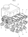
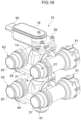
- Fig. 1 is a perspective view illustrating an overall configuration of a flow path switching valve 10 according to an embodiment of the disclosure.
- three valve units 20 are connected in the left-right direction, and the other valve units 20 are respectively stacked on the lower side of each valve unit 20. That is, six valve units 20 are combined.
- Fig. 4 is a partially broken perspective view illustrating a flow path switching valve in which two valve units 20 are stacked and two valve bodies are rotated by one rotation drive part.
- Fig. 4 corresponds to an example in which two upper and lower valve units 20 are extracted from Fig. 1 .
- Figs. 5 and 6 are partially broken perspective views illustrating one valve unit 20.
- the flow path switching valve 10 is used as, for example, a rotary three-way valve ( Fig. 5 ) or a four-way valve ( Fig. 13 and Fig. 14 ) that switches a flow path of a fluid flowing in an engine room or the like of an automobile. As illustrated in Figs. 4 to 8 , the flow path switching valve 10 has the valve unit 20 and a rotation drive part 18.
- the valve unit 20 includes a valve main body 14, a valve body 16, a first flow path 21, a second flow path 22, and a third flow path 23.
- the valve unit 20 is, for example, a three-way valve that switches between a state in which the first flow path 21 and the third flow path 23 communicate with each other, a state in which the second flow path 22 and the third flow path 23 communicate with each other, and a state in which the first flow path 21, the second flow path 22, and the third flow path 23 do not communicate with each other.
- the valve main body 14 is made of, for example, a synthetic resin, and a valve chamber 12 is formed at an interior therof. An upper direction of the valve chamber 12 is opened, and the valve body 16 and a sealing part 38 to be described later are inserted from the upper direction.
- a first port 31 and a second port 32 which face each other and through which a fluid respectively flows in and out are formed.
- the first port 31 is formed on a rear wall surface of the valve chamber 12
- the second port 32 is formed on a front wall surface of the valve chamber 12. That is, the first port 31 and the second port 32 face each other in the front-rear direction of the valve chamber 12.
- a third port 33 is formed on a bottom surface of the valve chamber 12.
- the valve body 16 is a ball-shaped member made of, for example, a synthetic resin, and is rotatably disposed in the valve chamber 12.
- An insertion hole 16A into which a valve shaft 28 in the rotation drive part 18 is inserted is formed in an upper part of the valve body 16.
- the valve shaft 28 and the insertion hole 16A are engaged with each other around an axial direction of the valve shaft 28, and the rotation of the valve shaft 28 is transmitted to the valve body 16.
- the insertion hole 16A penetrates, for example, to a flow path 36 of the valve body 16.
- the flow path (internal flow path) 36 is provided at an interior of the valve body 16. Specifically, as illustrated in Fig. 9 , a lateral hole 36A leading from an outer periphery (side part) to the flow path 36 is formed in the valve body 16. A pilot hole 36C leading from an outer periphery (lower part) to the flow path 36 is formed in the valve body 16. The flow path 36 communicates from the lateral hole 36A to the pilot hole 36C.
- the lateral hole 36A can face the first port 31 or the second port 32.
- the valve body 16 in a state in which the lateral hole 36A does not face, the valve body 16 is in close contact with a seat member 40 described later and is closed.
- a rib 16B extending in a direction (up-down direction) toward the third port 33 is formed in the flow path 36 of the valve body 16.
- the rib 16B is, for example, a thin plate-shaped protrusion, and is formed, for example, on an inner wall on a far side of the lateral hole 36A in the flow path 36 of the valve body 16.
- sealing parts 38 for sealing between the valve body 16 and each of the first port 31 and the second port 32 are respectively provided.
- the sealing part 38 has, for example, a seat member 40 and an O-ring 42.
- the seat member 40 is made of, for example, a synthetic resin, and is formed in an annular shape having openings corresponding to the first port 31 and the second port 32.
- the seat members 40 are respectively disposed around the first port 31 and the second port 32 on an inner wall surface (front and rear wall surfaces of the valve chamber 12) of the valve main body 14.
- the valve body 16 is sandwiched between the two seat members 40, and is disposed so as to be rotatable and slidable while being in contact with each of the seat members 40.
- a space between the seat member 40 and the valve main body 14 is sealed by the O-ring 42, for example, airtightly and watertightly.
- the O-ring 42 is attached to, for example, an O-ring groove (not illustrated) formed in the seat member 40.
- polyphenylene sulfide PPS
- PTFE fluororesin
- synthetic rubber can be used for the O-ring 42.
- the rotation drive part 18 is a device that is connected to the valve unit 20 and rotates the valve body 16 such that the communication state of the first port 31, the second port 32, and the third port 33 is switched by means of the flow path of the valve body 16.
- the rotation drive part 18 is disposed above the valve main body 14 in the upper valve unit 20.
- a bracket 24 is fixed onto the upper valve main body 14, and the rotation drive part 18 is fixed onto the bracket 24 using, for example, a screw 26 ( Fig. 1 ).
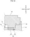
- An upward opening ( Fig. 5 ) in the valve chamber 12 of the upper valve main body 14 is closed by, for example, the bracket 24 ( Fig. 12 ).
- the bracket 24 has a shape that closes the opening of the valve chamber 12.
- the bracket 24 is welded to the inside of the opening of the valve chamber 12 in a state of being inlay fitted.
- the bracket 24 is provided with a convex part 30.
- the convex part 30 faces or abuts on an edge around the valve chamber 12 in the valve main body 14.
- the convex part 30 may be a melting margin.
- the convex part 30 may be provided on the valve main body 14 instead of the bracket 24.
- the rotation drive part 18 is, for example, a geared motor.
- the rotation drive part 18 is provided with, for example, a connector 50 to which wiring for communication with a control unit and power supply is coupled.
- the valve shaft 28 as an output shaft is coupled to the rotation drive part 18.
- the valve shaft 28 is inserted through a through-hole 24A formed in the bracket 24.
- An O-ring 29 or an X-ring (not illustrated) is attached to the valve shaft 28.
- the O-ring 29 ensures watertightness between the valve shaft 28 and the through-hole 24A.
- a lower end of the valve shaft 28 is inserted into the insertion hole 16A ( Fig. 5 ) of the valve body 16.
- the first flow path 21, the second flow path 22, and the third flow path 23 are, for example, pipe parts integrally configured with the valve main body 14.
- the first flow path 21 is a first port
- the second flow path 22 is a second port
- the third flow path 23 is a third port.
- the first flow path 21 is open at both ends, for example, and communicates with the first port 31 of the valve chamber 12.
- the first flow path 21 linearly extends, for example, in the left-right direction.
- the first port 31 is coupled to the middle of the first flow path 21.
- the first flow path 21 and the first port 31 are formed in a substantially T shape in plan view (see Figs. 13 and 14 ).
- the second flow path 22 is provided alongside the first flow path 21 with the valve main body 14 interposed therebetween, and has, for example, both ends opened and communicates with the second port 32.
- the second flow path 22 linearly extends, for example, in the left-right direction.
- the second port 32 is coupled to the middle of the second flow path 22.
- the second flow path 22 and the second port 32 are formed in a substantially T shape in plan view (see Figs. 13 and 14 ).
- female joints 51 and 52 are respectively provided at one ends of the first flow path 21 and the second flow path 22.
- male joints 61 and 62 are respectively provided at the other ends of the first flow path 21 and the second flow path 22.
- the male joints 61 and 62 are configured to be able to be coupled to the female joints 51 and 52.
- Annular grooves 61A and 62A are formed on the outer peripheries of the male joints 61 and 62.
- a pair of arc-shaped slits 51A and 52A are formed in the female joints 51 and 52.
- the male joints 61 and 62 are respectively fitted into the female joints 51 and 52, and are prevented from coming off by fitting clips 34 into the grooves 61A and 62A through the slits 51A and 52A.
- the water-tightening of the coupling portion of each joint is performed by, for example, an O-ring 66.
- the first flow path 21 and the second flow path 22 of one valve unit 20 can be respectively connected and coupled to the first flow path 21 and the second flow path 22 of another valve unit 20 (see Figs. 1 , 13 , and 14 ).
- the joint structure is an example, and any other joint structure can be used.
- a first protrusion part 71 protruding from the first port 31 side toward an interior of the first flow path 21 is provided at a connection part with the first port 31 in the first flow path 21.
- the first protrusion part 71 is, for example, an arc-shaped projection formed along the opening of the first port 31 with respect to the first flow path 21.
- the range of the first protrusion part 71 is, for example, less than half the circumference of an inner peripheral surface of the first flow path 21 on the first port 31 side.
- One surface of the first protrusion part 71 in the left-right direction is a concave surface obtained by extending a part of an inner wall of the first flow path 21.
- the first protrusion part 71 is provided on the left side of the first port 31.
- the first protrusion part 71 may be provided on the right side of the first port 31, or may be provided on both left and right sides of the first protrusion part 71.
- a second protrusion part 72 protruding from the second port 32 side toward an interior of the second flow path 22 is provided at a connection part with the second port 32 in the second flow path 22.
- the second protrusion part 72 is, for example, an arc-shaped projection formed along the opening of the second port 32 with respect to the second flow path 22.
- the range of the second protrusion part 72 is, for example, less than half the circumference of an inner peripheral surface of the second flow path 22 on the second port 32.
- One surface of the second protrusion part 72 in the left-right direction is a concave surface obtained by extending a part of an inner wall of second flow path 22.
- the second protrusion part 72 is provided on the left side of the second port 32.
- the second protrusion part 72 may be provided on the right side of the second port 32, or may be provided on both left and right sides of the second protrusion part 72.
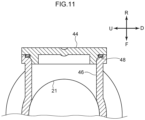
- a sub flow path 46 closed by a lid body 44 may be provided at a position facing the first port 31 in the first flow path 21.
- a space between the lid body 44 and the end of the sub flow path 46 is sealed by welding or is water-tight by a sealing member such as an O-ring 48.
- the sub flow path 46 can also be used by removing the lid body 44.
- a storage tank 54 is connectable to the sub flow path 46.
- the two sub flow paths 46 is also connectable to the storage tank 54 provided with two coupling ports ( Fig. 2 ).
- the storage tank 54 may have two storage chambers that correspond to the respective coupling ports and are partitioned from each other. As a result, fluids having different temperatures can be stored separately even in the same fluid.
- Pumps 81 and 82 can be respectively attached to the female joint 51 or the male joint 61 of the first flow path 21 at a terminal end of the flow path switching valve 10 and the female joint 52 or the female joint 62 of the second flow path 22 at a terminal end.
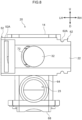
- the pump 81 is attached to the female joint 51 (see Fig. 2 ) of the first flow path 21 in the upper valve unit 20.
- the pump 82 is attached to the female joint 52 of the second flow path 22 in the upper valve unit 20.
- the pump 81 has a joint 91 serving as a fluid port.
- the pump 82 also has a joint 92 serving as a fluid port.
- the pump 81 can supply a fluid from the other device to the first flow path 21 or supply a fluid in the first flow path 21 to the other device via the joint 91.
- the pump 82 can supply a fluid from the other device to the second flow path 22 or supply a fluid in the second flow path 22 to the other device via the joint 92.
- the third flow path 23 communicates with the third port 33, and the opposite side from the third port 33 is opened.
- the third flow path 23 has a bent part 23A.
- the third port 33 is positioned above the bent part 23A.
- a terminal end of the third flow path 23 on the opening side is positioned, for example, in front of the bent part 23A, and protrudes, for example, forward of the second flow path 22.
- a male joint 64 that is connectable to a pipe to the other device is provided at the terminal end of the third flow path 23 on the opening side.
- a spherical concave part 23B is provided at a portion of the bent part 23A of the third flow path 23, facing the third port 33, that is, below the third port 33.
- the concave part 23B is formed in a substantially hemispherical shape.
- the concave part 23B is recessed downward from a bottom 23C of the lateral flow path on the front side of the bent part 23A.
- a through-hole 23D is formed at a bottom of the concave part 23B.
- a valve shaft 58 can pass through the through-hole 23D ( Fig. 4 ).
- a space between the valve shaft 58 and the through-hole 23D is water-tight by an O-ring 60.
- the other valve unit is not stacked on the lower side, like the lower valve unit 20 in Fig. 4 , for example, a structure without the through-hole 23D at the bottom of the concave part 23B is adopted.
- the through-hole 23D may be provided or may be closed by another member (for example, a closing part 86).
- the closing part 86 may include a temperature sensor 84.
- the temperature sensor 84 is supported by, for example, the closing part 86, and is disposed such that a distal end thereof is positioned in the third flow path 23.
- an O-ring 88 is attached to the closing part 86.
- the O-ring 88 ensures watertightness between the closing part 86 and the through-hole 23D.
- the other valve unit 20 can be stacked at and connected to the opposite side from the rotation drive part 18 of one valve unit 20.
- a portion of the upper valve unit 20 at which the lower valve unit 20 is stacked includes a lid 68 that closes the valve chamber 12 of the lower valve unit 20.
- the closing structure is substantially the same as the closing structure of the valve chamber 12 by the bracket 24 in Fig. 12 , and a bottom part of the upper valve main body 14 is welded in a state of being inlay fitted to the inside of the opening of the valve chamber 12 in the lower valve main body 14.
- the other valve unit 20 may be stacked at and connected to one valve unit 20, and two valve bodies 16 in two valve units 20 may be rotated by one rotation drive part 18.
- the valve shaft 28 of the upper valve unit 20 and the valve shaft 58 of the lower valve unit 20 are connected by a connecting shaft 56.
- the connecting shaft 56 connects the upper and lower valve shafts 28 and 58 through the interior of the upper valve body 16 and the longitudinal flow path of the third flow path 23.
- the rotation drive parts 18 may be respectively provided in the upper and lower valve units 20, and the rotation control of the valve body 16 may be performed separately.
- the present embodiment is configured as described above, and the operation thereof will be described below.
- the communication state of the first port 31, the second port 32, and the third port 33 of the valve chamber 12 can be selectively switched, for example, by means of the flow path 36 of the valve body 16 by rotating the valve body 16 by the rotation drive part 18. Since the first port 31 and the second port 32 face each other with the valve chamber 12 interposed therebetween, and one lateral hole 36A is formed in the valve body 16, switching of the flow path can be performed by rotating the valve body 16 by 180°.
- first flow path 21 and the second flow path 22 of one valve unit 20 can be respectively connected and coupled to the first flow path 21 and the second flow path 22 of the other valve unit 20, it is possible to easily realize flow path switching valves of various specifications by combining the valve units 20.
- the female joints 51 and 52 are respectively provided at one ends of the first flow path 21 and the second flow path 22, and the male joints 61 and 62 are respectively provided at the other ends of the first flow path 21 and the second flow path 22.
- the male joints 61 and 62 can be respectively coupled to the female joints 51 and 52. Therefore, for example, the first flow paths 21 and the second flow paths 22 of one valve unit 20 and the other valve unit 20 can be easily coupled to each other.
- the fluid flowing from the valve chamber 12 into the third flow path 23 through the third port 33 passes through the bent part 23A.
- the spherical concave part 23B is provided in a portion of the bent part 23A of the third flow path 23, facing the third port 33, the resistance of the fluid is reduced as compared with a configuration in which the concave part 23B is not provided in the portion and simply bent. Therefore, a pressure loss in the third flow path 23 can be suppressed.
- the other valve unit 20 can be stacked at and connected to the opposite side from to the rotation drive part 18 of one valve unit 20, such that the degree of freedom in combining the valve units 20 can be increased.
- a portion of one valve unit 20 at which another valve unit 20 is stacked includes the lid 68 that closes the valve chamber 12 of the other valve unit 20, when one valve unit 20 and another valve unit 20 are stacked, another component for closing the valve chamber 12 of the other valve unit 20 is unnecessary. Therefore, it is possible to suppress an increase in the number of components and to increase workability when the valve units 20 are stacked and connected.
- the valve unit 20 is not limited to the three-way valve, and may be, for example, a four-way valve as illustrated in Figs. 13 and 14 .
- a lateral hole 36B joining from an outer periphery (side part) to the center of the lateral hole 36A is formed, for example, in a direction orthogonal to a rotation axis O1 of the valve body 16 and orthogonal to the lateral hole 36A.
- Figs. 15 and 16 in a flow path switching valve 10 according to the present modification, the structures of the female joints 51 and 52 and the male joints 61 and 62 are different from the structures illustrated in Figs. 1 to 8 .
- Figs. 15 and 16 illustrate the same flow path switching valve 10 from a different viewpoint.
- the pipe configuring the first flow path 21 is configured separately from the valve main body 14 in a component state, and is coupled to the valve main body 14 by welding, for example, at the time of assembly.
- the pipe part configuring the second flow path 22 is integrally configured with the valve main body 14 in a component state.
- valve shaft 28 inserted into the valve body 16 is separated from a stem 98 as an output shaft of the rotation drive part 18.
- a lower end of the stem 98 is inserted into the valve shaft 28.
- the rotation of the stem 98 is transmitted to the valve shaft 28.
- the valve shaft 28 can be shared with the valve shaft 58 of the other valve unit 20 (lower valve unit).
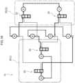
- a flow path switching valve 10 is configured by connecting two assemblies of the valve units 20 according to the second modification ( Figs. 15 and 16 ).
- the assembly of the valve units 20 is configured by stacking the two valve units 20.
- the two assemblies of the valve units 20 include a valve unit 20 (I) and a valve unit 20 (II) in order from the left side in Fig. 18 .
- a portion of the valve unit 20 (I) is indicated by a one-dot chain line, and a portion of the valve unit 20 (II) is indicated by a two-dot chain line.
- the valve unit 20 (I) is attached to the valve unit 20 (II) by rotating by 90°. Accordingly, the positions of the rotation drive parts 18 are also different from each other.
- a right side end of the second flow path is referred to as a port A
- a right side end of the first flow path is referred to as a port B
- a right side end of the second flow path is referred to as a port C
- a right side end of the first flow path is referred to as a port D.
- the third flow path is referred to as a port G.
- the third flow path is referred to as a port H.
- the port A communicates with the port E
- the port B communicates with the port G
- the port C communicates with the port H
- the port D communicates with the port F.
- the ports A and H, the ports B and E, the ports C and F, and the ports D and G are blocked respectively. Other unused ports are also blocked.
- a series flow path (series circuit) that returns to the port A through the ports A, E, F, D, B, G, H, and C can be configured.
- a heat exchanger, an evaporator, a condenser, a battery, a motor, and the like can be disposed in the external flow path.
- the port A communicates with the port H
- the port B communicates with the port E
- the port C communicates with the port F
- the port D communicates with the port G.
- the ports A and E, the ports B and G, the ports C and H, and the ports D and F are blocked respectively. Other unused ports are also blocked.
- a series flow path (series circuit) that returns to the port A through the ports A, H, G, D, B, E, F, and C can be configured.
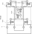
- a flow path switching valve 10 is configured by connecting three assemblies of the valve units 20 according to the second modification ( Figs. 15 and 16 ).
- the assembly of the valve units 20 is configured by stacking the two valve units 20.
- the first flow paths and the second flow paths are respectively connected in series, and a valve unit 20 (I) and a valve unit 20 (II) are formed in this order from the left side in Fig. 21 .
- the third valve unit 20 is referred to as a valve unit 20 (III).
- valve unit 20 (I) A portion of the valve unit 20 (I) is indicated by a thick one-dot chain line, a portion of the valve unit 20 (II) is indicated by a two-dot chain line, and a portion of the valve unit 20 (III) is indicated by a thin one-dot chain line.
- the valve unit 20 (III) is connected to the front surfaces of the valve unit 20 (I) and the valve unit 20 (II) in Fig. 21 . Specifically, the third flow path of the valve unit 20 (I) and the valve unit 20 (II) are coupled to the first flow path and the second flow path of the valve unit 20 (III).
- a right side end of the second flow path is referred to as a port A
- a right side end of the first flow path is referred to as a port B
- a right side end of the second flow path is referred to as a port C
- a right side end of the first flow path is referred to as a port D.
- the first flow path is referred to as a port E
- the second flow path is referred to as a port G
- the third flow path is referred to as a port J.
- the first flow path is referred to as a port F
- the second flow path is referred to as a port H
- the third flow path is referred to as a port K.
- the port A communicates with the port E
- the port B communicates with the port G
- the port C communicates with the port F
- the port D communicates with the port H
- the port G communicates with the port J
- the port H communicates with the port K.
- the ports A and G, the ports B and E, the ports C and H, the ports D and F, the ports E and J, and the ports F and K are blocked respectively. Other unused ports are also blocked.
- a series flow path returning to the port A through the ports A, E, F, and C can be configured.
- a series flow path that returns to the port B through the ports B, G, J, K, H, and D can be configured.
- the port A communicates with the port G
- the port B communicates with the port E
- the port E also communicates with the port J
- the port C communicates with the port H
- the port D communicates with the port F
- the port F also communicates with the port K.
- the ports A and E, the ports B and G, the ports C and F, the ports D and H, the ports G and J, and the ports H and K are blocked respectively. Ports that are not used are also blocked.
- a series flow path returning to the port A through the ports A, G, H, and C can be configured.
- a series flow path that returns to the port B through the ports B, E, J, K, F, and D can be configured.
- two series flow paths (series circuits) can coexist in any switching mode.
- the flow can be switched by the two switching modes.
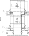
- a flow path switching valve 10 is obtained by rotating a valve unit 20 (III) on the front side by 90° and attaching the valve unit in the fifth modification ( Fig. 21 ).
- the ports A to D are similar to those in the fifth modification.
- the first flow path is referred to as a port G
- the second flow path is referred to as a port H
- the third flow path is referred to as a port J.
- the first flow path is referred to as a port E
- the second flow path is referred to as a port F
- the third flow path is referred to as a port K.
- the port A communicates with the port E.
- the port E also communicates with the port K.
- the port B communicates with the port G.
- the port G also communicates with the port J.
- the ports A and G, the ports B and E, the ports C and F, the ports D and H, the ports F and K, and the ports H and J are blocked respectively.
- the ports D and F communicate with each other and the ports C and H communicate with each other, the flow of each path is blocked by the valve unit (III). Other unused ports are also blocked.
- the port A communicates with the port G
- the port B communicates with the port E
- the port C communicates with the port F
- the port D communicates with the port H.
- the ports A and E, the ports B and G, the ports C and H, the ports D and F, the ports E and K, the ports F and K, the ports G and J, and the ports H and J are blocked respectively. Other unused ports are also blocked.
- a flow path switching valve 10 is configured by connecting three assemblies of the valve units 20 according to the second modification ( Figs. 15 and 16 ).
- the assembly of the valve units 20 is configured by stacking the two valve units 20.
- the two assemblies of the valve units 20 include a valve unit 20 (I), a valve unit 20 (II), and a valve unit 20 (III) in this order from the left side in Fig. 18 .
- the valve unit 20 (II) is attached by rotating by 180° with respect to the valve units 20 (I) and 20 (III).
- the female joints 51 and 52 are respectively provided at one ends of the first flow path 21 and the second flow path 22, and the male joints 61 and 62 having a structure that is connectable to the female joints 51 and 52 is provided at another end of each of the first flow path 21 and the second flow path 22.
- a joint structure may not be provided.
- the concave part 23B is provided in the bent part 23A of the third flow path 23, the concave part 23B may not be provided.
- the rib 16B is formed in the flow path 36 of the valve body 16, such a configuration without the rib 16B may be adopted.
- first protrusion part 71 is provided at the connection part with the first port 31 in the first flow path 21 and the second protrusion part 72 is provided at the connection part with the second port 32 in the second flow path 22, either the first protrusion part 71 or the second protrusion part 72 may be provided, or the first protrusion part 71 and the second protrusion part 72 may not be provided.
- valve unit 20 can be stacked at and connected to the opposite side from the rotation drive part 18 of one valve unit 20, another member may be interposed between the two valve units 20. Such connection need not be possible.
- the valve units 20 are stacked in two stages, but may be stacked in three or more stages.
Landscapes
- Engineering & Computer Science (AREA)
- General Engineering & Computer Science (AREA)
- Mechanical Engineering (AREA)
- Multiple-Way Valves (AREA)
Applications Claiming Priority (2)
| Application Number | Priority Date | Filing Date | Title |
|---|---|---|---|
| JP2022120888 | 2022-07-28 | ||
| PCT/JP2023/024521 WO2024024400A1 (ja) | 2022-07-28 | 2023-06-30 | 流路切換弁 |
Publications (1)
| Publication Number | Publication Date |
|---|---|
| EP4563853A1 true EP4563853A1 (en) | 2025-06-04 |
Family
ID=89706080
Family Applications (1)
| Application Number | Title | Priority Date | Filing Date |
|---|---|---|---|
| EP23846133.9A Pending EP4563853A1 (en) | 2022-07-28 | 2023-06-30 | Flow path switching valve |
Country Status (4)
| Country | Link |
|---|---|
| EP (1) | EP4563853A1 (https=) |
| JP (2) | JP7720665B2 (https=) |
| CN (1) | CN119546893A (https=) |
| WO (1) | WO2024024400A1 (https=) |
Families Citing this family (2)
| Publication number | Priority date | Publication date | Assignee | Title |
|---|---|---|---|---|
| JP2025172638A (ja) * | 2024-05-13 | 2025-11-26 | 株式会社不二工機 | 流路切換弁 |
| JP2025172637A (ja) * | 2024-05-13 | 2025-11-26 | 株式会社不二工機 | 流路切換弁 |
Family Cites Families (6)
| Publication number | Priority date | Publication date | Assignee | Title |
|---|---|---|---|---|
| JP5560006B2 (ja) * | 2009-08-20 | 2014-07-23 | 株式会社不二工機 | 複合弁 |
| JP6003716B2 (ja) * | 2012-04-17 | 2016-10-05 | 株式会社デンソー | 流路切替装置 |
| EP2843276B1 (de) * | 2013-08-28 | 2016-01-06 | Thomas Netzel | Rotationsventil |
| JP6737492B2 (ja) * | 2016-02-10 | 2020-08-12 | アドバンス電気工業株式会社 | バルブ及びこれを用いたマニホールドバルブ |
| CN111828682A (zh) | 2019-04-17 | 2020-10-27 | 浙江三花汽车零部件有限公司 | 一种控制阀 |
| JP2022120888A (ja) | 2021-02-08 | 2022-08-19 | 本田技研工業株式会社 | 射出成形方法及び射出成形装置 |
-
2023
- 2023-06-30 JP JP2024536884A patent/JP7720665B2/ja active Active
- 2023-06-30 EP EP23846133.9A patent/EP4563853A1/en active Pending
- 2023-06-30 WO PCT/JP2023/024521 patent/WO2024024400A1/ja not_active Ceased
- 2023-06-30 CN CN202380017840.6A patent/CN119546893A/zh active Pending
-
2025
- 2025-07-22 JP JP2025122466A patent/JP2025157479A/ja active Pending
Also Published As
| Publication number | Publication date |
|---|---|
| JP2025157479A (ja) | 2025-10-15 |
| WO2024024400A1 (ja) | 2024-02-01 |
| CN119546893A (zh) | 2025-02-28 |
| JP7720665B2 (ja) | 2025-08-08 |
| JPWO2024024400A1 (https=) | 2024-02-01 |
Similar Documents
| Publication | Publication Date | Title |
|---|---|---|
| EP4563853A1 (en) | Flow path switching valve | |
| KR102355554B1 (ko) | 유로 전환 밸브 | |
| JP2026062977A (ja) | 流路切換弁 | |
| CN216715302U (zh) | 控制阀、换热系统及汽车 | |
| EP4589182A1 (en) | Flow path switching valve | |
| JP7821489B2 (ja) | 流路切換弁 | |
| EP4692609A1 (en) | Flow path switching valve | |
| EP4589183A1 (en) | Flow path switching valve | |
| CN223648622U (zh) | 流路切换阀 | |
| EP4729812A1 (en) | Fluid control valve | |
| EP4671579A1 (en) | FLOW PASSAGE SWITCHING VALVE | |
| WO2025120900A1 (ja) | 流路切換弁 | |
| JP7517728B2 (ja) | 流路切換弁 | |
| CN222255138U (zh) | 一种汽车热管理系统用五通阀、热管理总成 | |
| CN223447784U (zh) | 流路切换阀 | |
| JP7549369B2 (ja) | 流路切換弁 | |
| CN116771953A (zh) | 控制阀 | |
| JP2024017709A (ja) | 冷却モジュール | |
| CN116771954A (zh) | 控制阀 | |
| CN119998577A (zh) | 用于流体回路的多通阀 |
Legal Events
| Date | Code | Title | Description |
|---|---|---|---|
| STAA | Information on the status of an ep patent application or granted ep patent |
Free format text: STATUS: THE INTERNATIONAL PUBLICATION HAS BEEN MADE |
|
| PUAI | Public reference made under article 153(3) epc to a published international application that has entered the european phase |
Free format text: ORIGINAL CODE: 0009012 |
|
| STAA | Information on the status of an ep patent application or granted ep patent |
Free format text: STATUS: REQUEST FOR EXAMINATION WAS MADE |
|
| 17P | Request for examination filed |
Effective date: 20240813 |
|
| AK | Designated contracting states |
Kind code of ref document: A1 Designated state(s): AL AT BE BG CH CY CZ DE DK EE ES FI FR GB GR HR HU IE IS IT LI LT LU LV MC ME MK MT NL NO PL PT RO RS SE SI SK SM TR |
|
| DAV | Request for validation of the european patent (deleted) | ||
| DAX | Request for extension of the european patent (deleted) |