EP4563352A1 - Anlage zum bereitstellen belichteter und abgekanteter druckplatten - Google Patents
Anlage zum bereitstellen belichteter und abgekanteter druckplatten Download PDFInfo
- Publication number
- EP4563352A1 EP4563352A1 EP23213247.2A EP23213247A EP4563352A1 EP 4563352 A1 EP4563352 A1 EP 4563352A1 EP 23213247 A EP23213247 A EP 23213247A EP 4563352 A1 EP4563352 A1 EP 4563352A1
- Authority
- EP
- European Patent Office
- Prior art keywords
- module
- printing plates
- exposed
- loading
- exposure
- Prior art date
- Legal status (The legal status is an assumption and is not a legal conclusion. Google has not performed a legal analysis and makes no representation as to the accuracy of the status listed.)
- Pending
Links
Images

Classifications
-
- B—PERFORMING OPERATIONS; TRANSPORTING
- B41—PRINTING; LINING MACHINES; TYPEWRITERS; STAMPS
- B41F—PRINTING MACHINES OR PRESSES
- B41F27/00—Devices for attaching printing elements or formes to supports
-
- G—PHYSICS
- G03—PHOTOGRAPHY; CINEMATOGRAPHY; ANALOGOUS TECHNIQUES USING WAVES OTHER THAN OPTICAL WAVES; ELECTROGRAPHY; HOLOGRAPHY
- G03F—PHOTOMECHANICAL PRODUCTION OF TEXTURED OR PATTERNED SURFACES, e.g. FOR PRINTING, FOR PROCESSING OF SEMICONDUCTOR DEVICES; MATERIALS THEREFOR; ORIGINALS THEREFOR; APPARATUS SPECIALLY ADAPTED THEREFOR
- G03F7/00—Photomechanical, e.g. photolithographic, production of textured or patterned surfaces, e.g. printing surfaces; Materials therefor, e.g. comprising photoresists; Apparatus specially adapted therefor
- G03F7/70—Microphotolithographic exposure; Apparatus therefor
- G03F7/70691—Handling of masks or workpieces
- G03F7/70733—Handling masks and workpieces, e.g. exchange of workpiece or mask, transport of workpiece or mask
-
- B—PERFORMING OPERATIONS; TRANSPORTING
- B41—PRINTING; LINING MACHINES; TYPEWRITERS; STAMPS
- B41F—PRINTING MACHINES OR PRESSES
- B41F27/00—Devices for attaching printing elements or formes to supports
- B41F27/12—Devices for attaching printing elements or formes to supports for attaching flexible printing formes
- B41F27/1287—Devices for attaching printing elements or formes to supports for attaching flexible printing formes devices for bending the printing plates or the printing plate ends
-
- G—PHYSICS
- G03—PHOTOGRAPHY; CINEMATOGRAPHY; ANALOGOUS TECHNIQUES USING WAVES OTHER THAN OPTICAL WAVES; ELECTROGRAPHY; HOLOGRAPHY
- G03F—PHOTOMECHANICAL PRODUCTION OF TEXTURED OR PATTERNED SURFACES, e.g. FOR PRINTING, FOR PROCESSING OF SEMICONDUCTOR DEVICES; MATERIALS THEREFOR; ORIGINALS THEREFOR; APPARATUS SPECIALLY ADAPTED THEREFOR
- G03F7/00—Photomechanical, e.g. photolithographic, production of textured or patterned surfaces, e.g. printing surfaces; Materials therefor, e.g. comprising photoresists; Apparatus specially adapted therefor
- G03F7/70—Microphotolithographic exposure; Apparatus therefor
- G03F7/70691—Handling of masks or workpieces
- G03F7/70733—Handling masks and workpieces, e.g. exchange of workpiece or mask, transport of workpiece or mask
- G03F7/7075—Handling workpieces outside exposure position, e.g. SMIF box
-
- G—PHYSICS
- G03—PHOTOGRAPHY; CINEMATOGRAPHY; ANALOGOUS TECHNIQUES USING WAVES OTHER THAN OPTICAL WAVES; ELECTROGRAPHY; HOLOGRAPHY
- G03F—PHOTOMECHANICAL PRODUCTION OF TEXTURED OR PATTERNED SURFACES, e.g. FOR PRINTING, FOR PROCESSING OF SEMICONDUCTOR DEVICES; MATERIALS THEREFOR; ORIGINALS THEREFOR; APPARATUS SPECIALLY ADAPTED THEREFOR
- G03F7/00—Photomechanical, e.g. photolithographic, production of textured or patterned surfaces, e.g. printing surfaces; Materials therefor, e.g. comprising photoresists; Apparatus specially adapted therefor
- G03F7/70—Microphotolithographic exposure; Apparatus therefor
- G03F7/708—Construction of apparatus, e.g. environment aspects, hygiene aspects or materials
- G03F7/70991—Connection with other apparatus, e.g. multiple exposure stations, particular arrangement of exposure apparatus and pre-exposure and/or post-exposure apparatus; Shared apparatus, e.g. having shared radiation source, shared mask or workpiece stage, shared base-plate; Utilities, e.g. cable, pipe or wireless arrangements for data, power, fluids or vacuum
-
- B—PERFORMING OPERATIONS; TRANSPORTING
- B41—PRINTING; LINING MACHINES; TYPEWRITERS; STAMPS
- B41C—PROCESSES FOR THE MANUFACTURE OR REPRODUCTION OF PRINTING SURFACES
- B41C1/00—Forme preparation
- B41C1/10—Forme preparation for lithographic printing; Master sheets for transferring a lithographic image to the forme
- B41C1/1075—Mechanical aspects of on-press plate preparation
-
- B—PERFORMING OPERATIONS; TRANSPORTING
- B41—PRINTING; LINING MACHINES; TYPEWRITERS; STAMPS
- B41C—PROCESSES FOR THE MANUFACTURE OR REPRODUCTION OF PRINTING SURFACES
- B41C1/00—Forme preparation
- B41C1/10—Forme preparation for lithographic printing; Master sheets for transferring a lithographic image to the forme
- B41C1/1083—Mechanical aspects of off-press plate preparation
-
- B—PERFORMING OPERATIONS; TRANSPORTING
- B41—PRINTING; LINING MACHINES; TYPEWRITERS; STAMPS
- B41F—PRINTING MACHINES OR PRESSES
- B41F19/00—Apparatus or machines for carrying out printing operations combined with other operations
- B41F19/008—Apparatus or machines for carrying out printing operations combined with other operations with means for stamping or cutting out
-
- B—PERFORMING OPERATIONS; TRANSPORTING
- B41—PRINTING; LINING MACHINES; TYPEWRITERS; STAMPS
- B41F—PRINTING MACHINES OR PRESSES
- B41F27/00—Devices for attaching printing elements or formes to supports
- B41F27/06—Devices for attaching printing elements or formes to supports for attaching printing elements to forme cylinders
-
- B—PERFORMING OPERATIONS; TRANSPORTING
- B41—PRINTING; LINING MACHINES; TYPEWRITERS; STAMPS
- B41F—PRINTING MACHINES OR PRESSES
- B41F27/00—Devices for attaching printing elements or formes to supports
- B41F27/14—Devices for attaching printing elements or formes to supports for attaching printing formes to intermediate supports, e.g. adapter members
-
- B—PERFORMING OPERATIONS; TRANSPORTING
- B41—PRINTING; LINING MACHINES; TYPEWRITERS; STAMPS
- B41P—INDEXING SCHEME RELATING TO PRINTING, LINING MACHINES, TYPEWRITERS, AND TO STAMPS
- B41P2217/00—Printing machines of special types or for particular purposes
- B41P2217/10—Printing machines of special types or for particular purposes characterised by their constructional features
- B41P2217/11—Machines with modular units, i.e. with units exchangeable as a whole
-
- B—PERFORMING OPERATIONS; TRANSPORTING
- B41—PRINTING; LINING MACHINES; TYPEWRITERS; STAMPS
- B41P—INDEXING SCHEME RELATING TO PRINTING, LINING MACHINES, TYPEWRITERS, AND TO STAMPS
- B41P2227/00—Mounting or handling printing plates; Forming printing surfaces in situ
- B41P2227/40—Adjusting means for printing plates on the cylinder
-
- B—PERFORMING OPERATIONS; TRANSPORTING
- B41—PRINTING; LINING MACHINES; TYPEWRITERS; STAMPS
- B41P—INDEXING SCHEME RELATING TO PRINTING, LINING MACHINES, TYPEWRITERS, AND TO STAMPS
- B41P2227/00—Mounting or handling printing plates; Forming printing surfaces in situ
- B41P2227/50—Devices for storing printing plates
-
- B—PERFORMING OPERATIONS; TRANSPORTING
- B41—PRINTING; LINING MACHINES; TYPEWRITERS; STAMPS
- B41P—INDEXING SCHEME RELATING TO PRINTING, LINING MACHINES, TYPEWRITERS, AND TO STAMPS
- B41P2227/00—Mounting or handling printing plates; Forming printing surfaces in situ
- B41P2227/60—Devices for transferring printing plates
- B41P2227/62—Devices for introducing printing plates
-
- B—PERFORMING OPERATIONS; TRANSPORTING
- B41—PRINTING; LINING MACHINES; TYPEWRITERS; STAMPS
- B41P—INDEXING SCHEME RELATING TO PRINTING, LINING MACHINES, TYPEWRITERS, AND TO STAMPS
- B41P2227/00—Mounting or handling printing plates; Forming printing surfaces in situ
- B41P2227/60—Devices for transferring printing plates
- B41P2227/63—Devices for removing printing plates
-
- B—PERFORMING OPERATIONS; TRANSPORTING
- B41—PRINTING; LINING MACHINES; TYPEWRITERS; STAMPS
- B41P—INDEXING SCHEME RELATING TO PRINTING, LINING MACHINES, TYPEWRITERS, AND TO STAMPS
- B41P2233/00—Arrangements for the operation of printing presses
- B41P2233/10—Starting-up the machine
Definitions
- the invention relates to a system for providing exposed and bent printing plates with the features of the preamble of claim 1.
- the invention lies in the technical field of the graphic industry and, in particular, in the area of the production of exposed printing plates, such as offset printing plates, as well as the bending of exposed printing plates in order to be able to mount and tension them on printing cylinders for printing.
- the EP0985528A1 , the DE202007011576U1 , the US6354208B1 and the US8256348B1 disclose systems for exposing printing plates and for further processing the exposed printing plates, in particular bending.
- the US7225737B2 discloses a method for the automated production of printing plates, wherein printing plates are exposed in an exposure unit and subsequently beveled.
- the beveling also takes place in the exposure unit, or the beveling device provided for this purpose is arranged adjacent to an exposure device.
- the EP3564036A1 discloses a method for exposing and automatically sorting printing plates.
- a system for providing exposed and folded printing plates which has the following modules: at least one loading module, which comprises a device for storing and feeding unexposed printing plates; an exposure module, which comprises a device for exposing fed printing plates; and a folding module, which comprises a device for folding exposed printing plates, is characterized in that the folding module and the loading module or one of the loading modules are combined to form a combination module in such a way that the device for folding exposed printing plates is arranged on the device for storing and feeding unexposed printing plates.
- the invention advantageously enables the implementation of imagesetters in a space-saving and thus potentially more cost-effective manner.
- the invention is primarily used in the graphic arts industry, particularly in the so-called prepress sector (pre-press).
- the inventive provision and use of a combination module saves floor space in the production facility.
- the combination module can combine the loading module and the bending module by simply stacking them on top of each other; alternatively, the loading module and the bending module can be integrated to form a new unit.
- the loading module of the combination module can accommodate the stored printing plates in cassettes, i.e., it can be designed as a so-called “cassette loader” (one cassette) or “dual cassette loader” (two or more cassettes).
- the loading module can accommodate the stored printing plates on a pallet, i.e., it can be designed as a so-called "pallet loader.”
- the following individual modules are already known in prepress (although they are space-consuming and arranged one after the other in a so-called "line"): loading module (loader), imaging module (imagesetter, CtP), bending module, stacking module, and possibly sorting module. Furthermore, a developing module is also already known in such "lines,” provided no processless printing plates are processed. In contrast, the invention is particularly advantageous for use in the processing of processless printing plates, since such plates do not require chemical development (i.e., the development module can be dispensed with), and any resulting bending is therefore less disruptive or non-disruptive in subsequent steps.
- the combo module includes a bending module
- its bending device does not need to be activated for every application. Rather, a computer-based decision can be made from plate to plate whether a bend needs to be created or not. For this purpose, a barcode or similar code can be detected on the plate and compared with the The need for bending can be evaluated. Alternatively, the necessary data can be provided by the prepress software.
- the printing plates can be moved parallel to the bend by certain predefined distances before or after bending, allowing the printing plates to be cascaded onto one another later during storage. This facilitates the removal of individual printing plates or multiple printing plates from a single print job from the storage module.
- the bending device can have a stop to which the printing plates to be processed are conveyed one after the other.
- a printing plate resting against the stop can be provided with a predetermined bend (preferably downward) using a bending tool, which preferably acts from above. After bending, the printing plate can be discharged or transferred to a subsequent station. For this purpose, the printing plate can preferably be moved under, through, or past the bending device.
- a storage module is provided, it is preferably designed in such a way that it can accommodate bent printing plates, e.g. in a corresponding recess or a shaft of the storage module.
- the printing plates to be processed are preferably offset printing plates. These are typically used in sheet-fed printing presses, e.g., in commercial or packaging printing; alternatively, they can be used in web-fed printing presses, e.g., in newspaper printing presses.
- developments Preferred developments of the invention (hereinafter referred to as “developments”) are described below. These can also be combined with one another where not technically impossible.
- a further development can be characterized in that the unexposed printing plates are fed to the exposure module from the loading module in a feed direction.
- a further development can be characterized in that the exposed printing plates are output from the exposure module in an output direction.
- a further development can be characterized in that the output direction is oriented opposite to the feed direction.
- a further development can be characterized in that the output direction is oriented with the feed direction.
- a further development can be characterized in that the device for bending exposed printing plates is arranged transversely to the output direction such that the leading edge of each output printing plate is folded.
- a further development can be characterized in that the folded printing plate is conveyed to a subsequent module, e.g., a storage module.
- a further development can be characterized by the printing plate being rotated and bent by 90° and conveyed to a subsequent module, e.g., a storage module.
- a further development can be characterized by the printing plate being rotated and bent by 90° and being turned back by 90° and conveyed to a subsequent module, e.g., a storage module.
- a further development can be characterized in that the loading module or one of the loading modules comprises a separating device which separates printing plates from interleaving paper.
- the exposure module comprises a punching device which is designed as a device for punching register punches into the printing plates.
- a further development can be characterized in that the system has at least one storage module, which includes a device for storing exposed and folded printing plates.
- the storage module includes an insertion device, which is designed as a device for inserting strips between stored printing plates.
- the system has a sorting module, which distributes the exposed and folded printing plates among several storage modules according to a sorting specification.
- a further development can be characterized in that the system comprises the following modules in functional succession: exposure module, combination module; or exposure module, combination module, storage module; or exposure module, combination module, sorting module, storage module; or loading module, exposure module, combination module, storage module; or loading module, exposure module, combination module, sorting module, storage module.
- a further development can be characterized by the fact that the modules present in the system - except for the combined modules of the combination module - are designed as separate modules, ie that the modules can be placed separately from one another (with or without spacing).
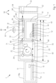
- Figure 1 shows a system 1 for preparing or producing exposed and bent printing plates 2.
- Each printing plate 2 comprises a leading edge 2a, on which a bevel 2b is created (for the subsequent mounting of the printing plate 2 on a printing plate cylinder).
- the stored printing plates 2 are separated from each other by interleaved papers 3 to protect them from damage.
- the system 1 comprises at least one loading module 10, with a device 11 for storing and feeding unexposed printing plates 2 and with a device 12 for separating and, if necessary, disposing of interleaving papers 3.
- the device 11 can accommodate a pallet 14 with the printing plates 2.
- the printing plates 2 can be one cassette or in several cassettes.
- the device 11 can be designed to accommodate both pallets and cassettes.
- the system 1 further comprises an exposure module 20 ("image setter”) with a device 21 for exposing the printing plates 2 fed from the loading module 10.
- the device 21 preferably comprises a cylinder 22 for receiving the printing plates 2 to be exposed and for rotating the printing plates 2 in a rotational direction 22a during exposure.
- the device 21 further comprises at least one exposure head 23, which preferably images the printing plates 2 with laser light, and optionally a punching device 24, which provides the printing plates 2 with register punches 2c.
- the printing plates 2 are fed to the exposure module 20 in a feed direction 70 (in the figure, for example, from the right) from the loading module 10, and the exposure module 20 delivers the printing plates 2 in an output direction 71 (in the figure, for example, to the right) to the following module (see below: bending module 30); Both directions can preferably be oriented in opposite directions to each other.
- the feed can be made at the bottom of one side of the exposure module 20 and the output at the top; a housing of the exposure module 20 can have suitable openings for this purpose.
- the feed can also be made at one side of the exposure module 20 (in the Figure 1 e.g., from the left) and the output on the opposite side (e.g., to the right in the figure).
- the feed can also be done manually (e.g., from the right in the figure).
- the system 1 further comprises a bending module 30 with a device 31 for bending exposed printing plates 2, i.e. for producing a respective bend 2b.
- the device 31 can be aligned transversely to the output direction 71 of the exposure module 20; alternatively, the device 31 can be aligned longitudinally to the output direction 71 (dash-dotted representation).
- the bending module 30 can further comprise a rotating device 32 which can rotate the exposed printing plates 2 about a vertical axis of rotation 33. By means of the rotating device 32, a printing plate 2 can be rotated, for example, by 90°, so that its front edge 2a can be aligned parallel to the respective orientation of the device 31. If the loading module 10 already has a rotating device 32 on its upper side, this can also be used.
- both modules 10 and 30 are arranged on the loading module 10, e.g., mounted on the loading module 10 and, in particular, fastened thereto.
- both modules 10 and 30 only require a common and therefore reduced footprint 61 (compared to the footprint of a system 1 without a combination module, i.e., with the loading module 10 and bending module 30 arranged next to one another).
- the footprint 62 of the system 1 is also reduced in this way.
- both modules 10 and 30 can form a unit, for example, having a common frame and/or common adjustable feet.
- the system 1 further optionally comprises one or more subsequent modules 50, e.g., a sorting module 51 and/or a storage module 52 with a device 53 for storing exposed and folded printing plates 2.
- the sorting module 51 serves to sort printing plates 2 according to the print jobs or the printing presses involved.
- the storage module 52 serves to receive/store the preferably already sorted printing plates 2 in order to transport them from there to the printing presses.
- the storage module 52 can comprise an insertion device 54, which can, for example, position paper strips between printing plates 2 of different print jobs.
- a plurality of storage modules 52 can preferably also be provided; these can, for example, be arranged along the sorting module 51.
- the system 1 optionally further comprises a further loading module 10a.
- This is preferably arranged on the opposite side of the exposure module 20 with respect to the loading module 10.
- the loading module 10a can also have a device 11 for storing and feeding printing plates 2 and a device 12 for separating interleaving papers 3.
- the loading module 10a can comprise a cassette 13 or several such cassettes for receiving unexposed printing plates 2.
- the printing plates 2 can be stored on a pallet.
- the device 11 can be designed to accommodate both pallets and cassettes.
- system 1 has transfer points or transfer devices 60 (e.g., rollers or belts for the preferably horizontal conveyance of the printing plates 2), at which the respective transfer between a module and a subsequent module takes place.
- the transfer points 60 are preferably of small horizontal dimensions, so that the footprint 62 of system 1 remains as small as possible.
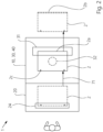
- Figure 2 shows the same system 1 from above, wherein only the combination module 40 (consisting of loading module 10 and bending module 30) and the exposure module 20 are shown. It can be seen that an exposed printing plate 2 is transferred from the exposure module 20 in the output direction 71 to the bending module 30 and, after bending, is output in the same direction 71 or transferred to a subsequent module 50.
- the rotating device 32 is not used here, i.e., it can be dispensed with in this embodiment if necessary. Therefore, the bend 2b is produced on the front edge 2a of the printing plate 2 transversely to the output direction 71.
- Figure 3 shows in comparison to Figure 2 a system 1 that performs the corresponding bending process using the rotating device 32.
- an exposed printing plate 2 is transferred from the exposure module 20 in the output direction 71 to the bending module 30.
- the printing plate 2 is rotated by 90° using the rotating device 32, and in this way the leading edge 2a of the printing plate 2 is aligned parallel to the device 31a for bending printing plates 2.
- the printing plate 2 can be output in its existing orientation or transferred to a subsequent module; alternatively, the printing plate 2 can be rotated back by 90° and only then output or transferred to a subsequent module (both alternatives are shown superimposed).
- a comparison of the two Figures 2 and 3 shows that in the system 1 shown, the bending module is arranged either parallel to the output direction 71 or transverse to the output direction 71.
- appropriate transport rollers or conveyor belts can be provided in the bending module 30, for example.
Landscapes
- Physics & Mathematics (AREA)
- General Physics & Mathematics (AREA)
- Engineering & Computer Science (AREA)
- Computer Networks & Wireless Communication (AREA)
- Health & Medical Sciences (AREA)
- Environmental & Geological Engineering (AREA)
- Epidemiology (AREA)
- Public Health (AREA)
- Exposure And Positioning Against Photoresist Photosensitive Materials (AREA)
Abstract
Description
- Die Erfindung betrifft eine Anlage zum Bereitstellen belichteter und abgekanteter Druckplatten mit den Merkmalen des Oberbegriffs von Anspruch 1.
- Die Erfindung liegt auf dem technischen Gebiet der grafischen Industrie und dort insbesondere im Bereich des Herstellens von belichteten Druckplatten, wie z.B. Offsetdruckplatten, sowie des Abkantens belichteter Druckplatten, um diese für das Abdrucken auf Druckzylinder aufziehen und spannen zu können.
- Die
EP0985528A1 , dieDE202007011576U1 , dieUS6354208B1 und dieUS8256348B1 offenbaren Anlagen für das Belichten von Druckplatten und für das Weiterverarbeiten der belichteten Druckplatten, insbesondere das Abkanten. - Die
US7225737B2 offenbart ein Verfahren zum automatisierten Herstellen von Druckplatten, wobei Druckplatten in einem Belichter belichtet und anschließend abgekantet werden. Das Abkanten findet ebenfalls in dem Belichter statt bzw. die dafür vorgesehene Abkantvorrichtung ist einer Vorrichtung zum Belichten benachbart angeordnet. - Die
EP3564036A1 offenbart ein Verfahren zum Belichten und automatischen Sortieren von Druckplatten. - Industriell genutzte Anlagen für das hochproduktive und -qualitative Belichten, Abkanten und für mögliche weitere Schritte der Druckplattenbehandlung können aufgrund ihrer Ausmaße viel Stellfläche fordern. In bestehenden Druckproduktionsstätten ist diese Stellfläche gegebenenfalls nicht vorhanden oder muss aufwändig geschaffen werden. Das Einsparen von Stellfläche ist daher mit Vorteilen verbunden und kann den Markterfolg einer solchen Anlage positiv beeinflussen.
- Es ist daher eine Aufgabe der vorliegenden Erfindung, eine Verbesserung gegenüber dem Stand der Technik zu schaffen, welche es insbesondere ermöglicht, Belichter-Anlagen platzsparend zu verwirklichen.
- Diese Aufgabe wird erfindungsgemäß durch eine Anlage nach Anspruch 1 gelöst.
- Vorteilhafte und daher bevorzugte Weiterbildungen der Erfindung ergeben sich aus den Unteransprüchen sowie aus der Beschreibung und den Zeichnungen.
- Eine erfindungsgemäße Anlage zum Bereitstellen belichteter und abgekanteter Druckplatten, welche folgende Module aufweist: wenigstes ein Belademodul, welches eine Vorrichtung zum Bevorraten und Zuführen von unbelichteten Druckplatten umfasst; ein Belichtungsmodul, welches eine Vorrichtung zum Belichten von zugeführten Druckplatten umfasst; und ein Abkantmodul, welches eine Vorrichtung zum Abkanten von belichteten Druckplatten umfasst, zeichnet sich dadurch aus, dass das Abkantmodul und das Belademodul oder eines der Belademodule derart zu einem Kombimodul zusammengefasst sind, dass die Vorrichtung zum Abkanten von belichteten Druckplatten auf der Vorrichtung zum Bevorraten und Zuführen von unbelichteten Druckplatten angeordnet ist.
- Die Erfindung ermöglicht es in vorteilhafter Weise, Belichter-Anlagen platzsparend und damit ggf. kostengünstiger zu verwirklichen. Die Erfindung kommt bevorzugt in der grafischen Industrie und insbesondere im sogenannten Prepress-Bereich (Druckvorstufe) zum Einsatz.
- Das erfindungsgemäße Bereitstellen und Einsetzen eines Kombimoduls spart Bodenfläche in der Produktionsstätte. Das Kombimodul kann dabei das Belademodul und das Abkantmodul durch einfaches Übereinanderanordnen zusammenfassen; alternativ können das Belademodul das Abkantmodul integriert werden und eine neue Einheit bilden.
- Das Belademodul des Kombimoduls kann die bevorrateten Druckplatten in Kassetten aufnehmen, d.h. als sogenannter "Cassette Loader" (eine Kassette) oder "Dual Cassette Loader" (zwei - oder auch mehr - Kassetten) ausgebildet sein. Alternativ kann das Belademodul die bevorrateten Druckplatten auf einer Palette aufnehmen, d.h. als sogenannter "Pallet Loader" ausgebildet sein.
- In der Druckvorstufe sind folgende einzelne Module bereits bekannt (allerdings platzraubend hintereinander aufgereiht als sogenannte "Straße"): Belademodul (loading module, loader), Belichtungsmodul (imaging module, Belichter, CtP), Abkantmodul (bending module), Speichermodul (stacking module) und ggf. Sortiermodul (sorting module). Darüber hinaus ist auch ein Entwicklungsmodul (developing module) in solchen "Straßen" bereits bekannt, sofern keine prozesslosen Druckplatten verarbeitet werden. Die Erfindung ist demgegenüber besonders vorteilhaft im Umfeld der Verarbeitung von prozesslosen Druckplatten einsetzbar, da solche Platten nicht chemisch entwickelt werden müssen (d.h. auf das Entwicklungsmodul somit verzichtet werden kann) und eine erzeugte Abkantung ist daher weniger oder nicht störend in Folgeschritten.
- Obgleich das Kombimodul ein Abkantmodul umfasst, muss dessen Abkantvorrichtung nicht bei jeder Anwendung aktiv werden. Vielmehr kann von Druckplatte zu Druckplatte rechentechnisch entschieden werden, ob eine Abkantung erzeugt werden muss oder nicht. Hierzu kann zum Beispiel ein Barcode o.ä. auf der Druckplatte erfasst und hinsichtlich der Notwendigkeit für eine Abkantung ausgewertet werden. Alternativ hierzu können notwendige Daten von der Vorstufen-Software bereitgestellt werden.
- Die Druckplatten können vor dem Abkanten oder nach dem Abkanten um gewisse vorgegebene Strecken parallel zur Abkantung verschoben werden, sodass die Druckplatten später beim Speichern kaskadiert aufeinander aufgelegt werden können. Dies erleichtert die Entnahme einzelner Druckplatten oder mehrerer Druckplatten eines gemeinsamen Druckauftrages aus dem Speichermodul.
- Die Abkantvorrichtung kann einen Anschlag aufweisen, an welchen die zu bearbeitenden Druckplatten nacheinander herangefördert werden. Eine am Anschlag anliegende Druckplatte kann mit einem Abkantwerkzeug, welches bevorzugt von oben wirkt, mit einer vorgegebenen Abkantung (bevorzugt nach unten) versehen werden. Nach erfolgtem Abkanten kann die Druckplatte ausgegeben oder an eine Folgestation übergeben werden. Hierzu kann die Druckplatte bevorzugt unter der Abkantvorrichtung hindurch, durch diese hindurch oder an dieser vorbei bewegt werden.
- Sofern ein Speichermodul vorgesehen ist, ist dieses bevorzugt derart ausgebildet, dass es abgekantete Druckplatten aufnehmen kann, z.B. in einer entsprechenden Ausnehmung oder einem Schacht des Speichermoduls.
- Bei den zu bearbeitenden Druckplatten handelt es sich bevorzugt um Offset-Druckplatten. Diese kommen bevorzugt in bogenverarbeitenden Druckmaschine zum Einsatz, z.B. im Akzidenzdruck oder Verpackungsdruck; alternativ können diese in Rollendruckmaschinen, z.B. in Zeitungsdruckmaschinen, zum Einsatz kommen.
- Im Folgenden werden bevorzugte Weiterbildungen der Erfindung (kurz: Weiterbildungen) beschrieben. Diese können - wo es sich nicht technisch ausschließt - auch untereinander kombiniert werden.
- Eine Weiterbildung kann sich dadurch auszeichnen, dass die unbelichteten Druckplatten dem Belichtungsmodul von dem Belademodul in einer Zuführrichtung zugeführt werden. Eine Weiterbildung kann sich dadurch auszeichnen, dass die belichteten Druckplatten von dem Belichtungsmodul in einer Ausgaberichtung ausgegeben werden. Eine Weiterbildung kann sich dadurch auszeichnen, dass die Ausgaberichtung entgegen der Zuführrichtung orientiert ist. Eine Weiterbildung kann sich dadurch auszeichnen, dass die Ausgaberichtung mit der Zuführrichtung orientiert ist.
- Eine Weiterbildung kann sich dadurch auszeichnen, dass die Vorrichtung zum Abkanten von belichteten Druckplatten derart quer zur Ausgaberichtung angeordnet ist, dass die Vorderkante einer jeweiligen ausgegebenen Druckplatte abgekantet wird. Eine Weiterbildung kann sich dadurch auszeichnen, dass die abgekantete Druckplatte zu einem Folgemodul, z.B. einem Speichermodul, gefördert wird.
- Eine Weiterbildung kann sich dadurch auszeichnen, dass das Belademodul oder eines der Belademodule oder das Abkantmodul eine Drehvorrichtung umfasst, welche als eine Vorrichtung zum Drehen der belichteten Druckplatten um eine zur Druckplattenebene senkrechte Achse (bevorzugt Vertikalachse) ausgebildet ist. Eine Weiterbildung kann sich dadurch auszeichnen, dass die Vorrichtung zum Abkanten von belichteten Druckplatten derart parallel zur Ausgaberichtung angeordnet ist, dass die Vorderkante einer jeweiligen ausgegebenen und um 90° gedrehten Druckplatte abgekantet wird.
- Eine Weiterbildung kann sich dadurch auszeichnen, dass die um 90° gedrehte und abgekantete Druckplatte zu einem Folgemodul, z.B. einem Speichermodul, gefördert wird. Eine Weiterbildung kann sich dadurch auszeichnen, dass die um 90° gedrehte und abgekantete Druckplatte um 90° zurückgedreht wird und zu einem Folgemodul, z.B. einem Speichermodul, gefördert wird.
- Eine Weiterbildung kann sich dadurch auszeichnen, dass das Belademodul oder eines der Belademodule eine Vorrichtung zum Trennen umfasst, welche Druckplatten von Zwischenlagepapier trennt.
- Eine Weiterbildung kann sich dadurch auszeichnen, dass die Vorrichtung zum Bevorraten und Zuführen von unbelichteten Druckplatten für das Bevorraten einer Mehrzahl an Druckplatten ausgebildet ist, wobei die Druckplatten in wenigstens einer Kassette oder auf einer Palette bevorratet sind. Eine Weiterbildung kann sich dadurch auszeichnen, dass die Vorrichtung zum Bevorraten und Zuführen von unbelichteten Druckplatten eine Mehrzahl von prozesslosen Druckplatten bevorratet und einzeln zuführt.
- Eine Weiterbildung kann sich dadurch auszeichnen, dass das Belichtungsmodul eine Stanzvorrichtung umfasst, welche als eine Vorrichtung zum Stanzen von Registerstanzungen in die Druckplatten ausgebildet ist.
- Eine Weiterbildung kann sich dadurch auszeichnen, dass die Anlage wenigstens ein Speichermodul aufweist, welches eine Vorrichtung zum Speichern von belichteten und abgekanteten Druckplatten umfasst. Eine Weiterbildung kann sich dadurch auszeichnen, dass das Speichermodul eine Einschießvorrichtung umfasst, welche als Vorrichtung zum Streifeneinschießen zwischen gespeicherte Druckplatten ausgebildet ist. Eine Weiterbildung kann sich dadurch auszeichnen, dass die Anlage ein Sortiermodul aufweist, welches die belichteten und abgekanteten Druckplatten auf mehrere Speichermodule gemäß einer Sortiervorgabe verteilt.
- Eine Weiterbildung kann sich dadurch auszeichnen, dass die Anlage folgende Module funktional aufeinander folgend umfasst: Belichtungsmodul, Kombimodul; oder Belichtungsmodul, Kombimodul, Speichermodul; oder Belichtungsmodul, Kombimodul, Sortiermodul, Speichermodul; oder Belademodul, Belichtungsmodul, Kombimodul, Speichermodul; oder Belademodul, Belichtungsmodul, Kombimodul, Sortiermodul, Speichermodul.
- Eine Weiterbildung kann sich dadurch auszeichnen, dass die in der Anlage vorhandenen Module - außer die kombinierten Module des Kombimoduls - als separate Module ausgebildet sind, d.h. dass die Module z.B. voneinander getrennt platziert werden können (mit oder ohne Abstand).
- Die in den obigen Abschnitten Technisches Gebiet, Erfindung und Weiterbildungen sowie im folgenden Abschnitt Ausführungsbeispiele offenbarten Merkmale und Merkmalskombinationen stellen - in beliebiger Kombination miteinander - weitere vorteilhafte Weiterbildungen der Erfindung dar.
- Die
Figuren 1 bis 3 zeigen bevorzugte Ausführungsbeispiele der Erfindung und der Weiterbildungen. Einander entsprechende Merkmale sind in den Figuren mit denselben Bezugszeichen versehen. Sich in den Figuren wiederholende Bezugszeichen wurden der Übersichtlichkeit teils weggelassen. -
Figur 1 zeigt eine schematische Darstellung einer Schnittansicht eines bevorzugen Ausführungsbeispiels einer erfindungsgemäßen Anlage. -
Figur 2 zeigt eine schematische Darstellung einer Draufsicht eines bevorzugen Ausführungsbeispiels einer erfindungsgemäßen Anlage. -
Figur 3 zeigt eine schematische Darstellung einer Draufsicht eines weiteren bevorzugen Ausführungsbeispiels einer erfindungsgemäßen Anlage. -
Figur 1 zeigt eine Anlage 1 zum Bereitstellen bzw. Erzeugen belichteter und abgekanteter Druckplatten 2. Jede Druckplatte 2 umfasst eine Vorderkante 2a, an welcher eine Abkantungen 2b (für das spätere Montieren der Druckplatte 2 auf einem Druckplattenzylinder) erzeugt wird. Die bevorrateten Druckplatten 2 sind zu deren Schutz vor Beschädigung durch Zwischenlagenpapiere 3 voneinander getrennt. - Die Anlage 1 umfasst wenigstens ein Belademodul 10, mit einer Vorrichtung 11 zum Bevorraten und Zuführen von unbelichteten Druckplatten 2 und mit einer Vorrichtung 12 zum Trennen und ggf. Entsorgen von Zwischenlagepapieren 3. Die Vorrichtung 11 kann eine Palette 14 mit den Druckplatten 2 aufnehmen. Alternativ können die Druckplatten 2 in einer Kassette oder in mehreren Kassetten bevorratet sein. Weiter alternativ kann die Vorrichtung 11 dazu ausgelegt sein, sowohl Paletten als auch Kassetten aufzunehmen.
- Die Anlage 1 umfasst weiterhin ein Belichtungsmodul 20 ("Belichter") mit einer Vorrichtung 21 zum Belichten der vom Belademodul 10 zugeführten Druckplatten 2. Die Vorrichtung 21 umfasst bevorzugt einen Zylinder 22 zur Aufnahme der zu belichtenden Druckplatten 2 und zum Rotieren der Druckplatten 2 in eine Drehrichtung 22a während des Belichtens. Die Vorrichtung 21 umfasst weiterhin mindestens einen Belichtungskopf 23, welcher die Druckplatten 2 bevorzugt mit Laserlicht bebildert, und optional eine Stanzvorrichtung 24, welche die Druckplatten 2 mit Registerstanzungen 2c versieht. Dem Belichtungsmodul 20 werden die Druckplatten 2 in einer Zuführrichtung 70 (in der Figur z.B. von rechts) von dem Belademodul 10 zugeführt und das Belichtungsmodul 20 gibt die Druckplatten 2 in einer Ausgaberichtung 71 (in der Figur z.B. nach rechts) an das folgende Modul (siehe unten: Abkantmodul 30) ab; beide Richtungen können bevorzugt gegenläufig zueinander orientiert sein. Die Zufuhr kann dabei an einer Seite des Belichtungsmodul 20 unten und die Ausgabe oben erfolgen; ein Gehäuse des Belichtungsmodul 20 kann hierzu passende Öffnungen aufweisen. Die Zufuhr kann auch an einer Seite des Belichtungsmoduls 20 (in der
Figur 1 z.B. von links) und die Ausgabe an der gegenüberliegenden Seite (in der Figur z.B. nach rechts) erfolgen. Die Zufuhr kann auch händisch erfolgen (in der Figur z.B. von rechts). - Die Anlage 1 umfasst weiterhin ein Abkantmodul 30 mit einer Vorrichtung 31 zum Abkanten von belichteten Druckplatten 2, d.h. zum Erzeugen einer jeweiligen Abkantung 2b. Die Vorrichtung 31 kann quer zu der Ausgaberichtung 71 des Belichtungsmodul 20 ausgerichtet sein; alternativ kann die Vorrichtung 31 längst zu der Ausgaberichtung 71 ausgerichtet sein (strichpunktierte Darstellung). Das Abkantmodul 30 kann weiterhin eine Drehvorrichtung 32 umfassen, welche die belichteten Druckplatten 2 um eine vertikale Drehachse 33 rotieren kann. Mittels der Drehvorrichtung 32 kann jeweils eine Druckplatte 2 z.B. um 90° gedreht werden, so dass deren Vorderkante 2a parallel zur jeweiligen Orientierung der Vorrichtung 31 ausgerichtet werden kann. Sofern das Belademodul 10 an seiner Oberseite bereits über eine Drehvorrichtung 32 verfügt, kann auch diese verwendet werden.
- In
Figur 1 ist deutlich erkennbar, dass das Abkantmodul 30 zusammen mit dem Belademodul 10 ein Kombimodul 40 bildet, insbesondere ist das Abkantmodul 30 auf dem Belademodul 10 angeordnet, z.B. auf das Belademodul 10 montiert und insbesondere auf diesem befestigt. Beide Module 10 und 30 beanspruchen auf diese Weise nur eine gemeinsame und daher verringerte Stellfläche 61 (im Vergleich zur Stellfläche einer Anlage 1 ohne Kombimodul, also mit nebeneinander angeordneten Belademodul 10 und Abkantmodul 30). Auch die Stellfläche 62 der Anlage 1 verringert sich auf diese Weise. Als Kombimodul 40 können beide Module 10 und 30 eine Einheit bilden, zum Beispiel ein gemeinsames Gestell und/oder gemeinsame Stellfüße aufweisen. - Die Anlage 1 umfasst weiterhin optional ein Folgemodul 50 oder mehrere Folgemodule 50, z.B. ein Sortiermodul 51 und/oder ein Speichermodul 52 mit einer Vorrichtung 53 zum Speichern von belichteten und abgekanteten Druckplatten 2. Das Sortiermodul 51 dient dabei dazu, Druckplatten 2 entsprechend der Druckaufträge bzw. der beteiligten Druckmaschinen zu sortieren. Das Speichermodul 52 dient dabei dazu, die bevorzugt bereits sortierten Druckplatten 2 aufzunehmen/zu speichern, um sie von dort zu den Druckmaschinen zu transportieren. Das Speichermodul 52 kann eine Einschießvorrichtung 54 umfassen, welche zum Beispiel Papierstreifen zwischen Druckplatten 2 unterschiedlicher Druckaufträge positionieren kann. Anstelle nur eines Speichermodules 52 kann bevorzugt auch eine Mehrzahl von Speichermodul und 52 vorgesehen sein; diese können zum Beispiel entlang des Sortiermoduls 51 angeordnet sein.
- Die Anlage 1 umfasst weiterhin optional ein weiteres Belademodul 10a. Dieses ist bezüglich des Belademoduls 10 bevorzugt auf der gegenüberliegenden Seite des Belichtungsmodul 20 angeordnet. Auch das Belademodul 10a kann eine Vorrichtung 11 zum Bevorraten und Zuführen von Druckplatten 2 und eine Vorrichtung 12 zum Trennen von Zwischenlagepapieren 3 aufweisen. Das Belademodul 10a kann eine Kassette 13 oder mehrere solcher Kassetten zur Aufnahme unbelichteter Druckplatten 2 umfassen. Alternativ können die Druckplatten 2 auf einer Palette bevorratet sein. Weiter alternativ kann die Vorrichtung 11 dazu ausgelegt sein, sowohl Paletten als auch Kassetten aufzunehmen.
- In
Figur 1 ist ebenfalls deutlich erkennbar, dass eine zu verarbeitende Druckplatte 2 zwischen den Modulen der Anlage 1 übergeben werden muss. Hierzu weist die Anlage 1 Übergabepunkte oder Übergabevorrichtungen 60 (z.B. Rollen oder Bänder zum bevorzugt horizontalen Fördern der Druckplatten 2) auf, an denen die jeweiligen Übergabe zwischen einem Modul und einem Folgemodul erfolgt. Die Übergabepunkte 60 sind bevorzugt von geringer horizontaler Abmessung, sodass die Stellfläche 62 der Anlage 1 insgesamt möglichst gering bleibt -
Figur 2 zeigt dieselbe Anlage 1 von oben, wobei nur das Kombimodul 40 (bestehend aus Belademodul 10 und Abkantmodul 30) und das Belichtungsmodul 20 gezeigt sind. Es ist erkennbar, dass eine belichtete Druckplatte 2 von dem Belichtungsmodul 20 in Ausgaberichtung 71 an das Abkantmodul 30 übergeben wird und nach dem Abkanten in derselben Richtung 71 ausgegeben oder an einem Folgemodul 50 übergeben wird. Die Drehvorrichtung 32 kommt dabei nicht zum Einsatz, d.h. gegebenenfalls kann auf sie in dieser Ausführungsform verzichtet werden. Daher wird die Abkantung 2b an der Vorderkante 2a der Druckplatte 2 quer zur Ausgaberichtung 71 erzeugt. -
Figur 3 zeigt im Vergleich zurFigur 2 eine Anlage 1, welche den entsprechenden Vorgang des Abkantens unter Einsatz der Drehvorrichtung 32 ausführt. Wieder wird eine belichtete Druckplatte 2 von dem Belichtungsmodul 20 in Ausgaberichtung 71 an das Abkantmodul 30 übergeben. Dort wird die Druckplatte 2 jedoch unter Einsatz der Drehvorrichtung 32 um 90° gedreht und auf diese Weise die Vorderkante 2a der Druckplatte 2 parallel zur Vorrichtung 31a zum Abkanten von Druckplatten 2 ausgerichtet. Nach dem Abkanten kann die Druckplatte 2 in der bestehenden Ausrichtung ausgegeben oder an ein Folgemodul übergeben werden; alternativ kann die Druckplatte 2 um 90° zurückgedreht werden und erst dann ausgegeben oder an ein Folgemodul übergeben werden (beide Alternativen sind überlagert dargestellt). - Ein Vergleich der beiden
Figuren 2 und3 lässt erkennen, dass in der jeweils gezeigten Anlage 1 das Abkantmodul entweder parallel zur Ausgaberichtung 71 oder quer zur Ausgaberichtung 71 angeordnet ist. Um die belichtete und abzukantende Druckplatte 2 durch das Abkantmodul 30 oder in dem Abkantmodul 30 zu fördern, können im Abkantmodul 30 z.B. entsprechende Transportrollen oder Transportbänder vorgesehen sein. -
- 1
- Anlage
- 2
- Druckplatte/-n
- 2a
- Vorderkante der Druckplatte
- 2b
- Abkantung
- 2c
- Registerstanzungen
- 3
- Zwischenlagepapier
- 10
- Belademodul
- 10a
- weiteres Belademodul
- 11
- Vorrichtung zum Bevorraten und Zuführen von Druckplatten
- 12
- Vorrichtung zum Trennen von Zwischenlagepapier
- 13
- Kassette
- 14
- Palette
- 20
- Belichtungsmodul
- 21
- Vorrichtung zum Belichten von Druckplatten
- 22
- Zylinder
- 22a
- Drehrichtung
- 23
- Belichtungskopf
- 24
- Stanzvorrichtung
- 30
- Abkantmodul
- 31
- Vorrichtung zum Abkanten von Druckplatten, in Querrichtung
- 31a
- Vorrichtung zum Abkanten von Druckplatten, alternativ in Längsrichtung
- 32
- Drehvorrichtung
- 33
- vertikale Drehachse
- 40
- Kombimodul
- 50
- Folgemodul/-e
- 51
- Sortiermodul
- 52
- Speichermodul/-e
- 53
- Vorrichtung zum Speichern von Druckplatten
- 54
- Einschießvorrichtung
- 60
- Übergabepunkt/-e, Übergabevorrichtung/-en
- 61
- Stellfläche des Kombimoduls
- 62
- Stellfläche der Anlage
- 70
- Zuführrichtung
- 71
- Ausgaberichtung
Claims (13)
- Anlage zum Bereitstellen belichteter und abgekanteter Druckplatten, welche folgende Module aufweist: wenigstes ein Belademodul (10), welches eine Vorrichtung (11) zum Bevorraten und Zuführen von unbelichteten Druckplatten (2) umfasst; ein Belichtungsmodul (20), welches eine Vorrichtung (21) zum Belichten von zugeführten Druckplatten (2) umfasst; und ein Abkantmodul (30), welches eine Vorrichtung (31) zum Abkanten von belichteten Druckplatten (2) umfasst,
dadurch gekennzeichnet,
dass das Abkantmodul (30) und das Belademodul (10) oder eines der Belademodule (10) derart zu einem Kombimodul (40) zusammengefasst sind, dass die Vorrichtung (31) zum Abkanten von belichteten Druckplatten (2) auf der Vorrichtung (11) zum Bevorraten und Zuführen von unbelichteten Druckplatten (2) angeordnet ist. - Anlage nach Anspruch 1,
dadurch gekennzeichnet,
dass die unbelichteten Druckplatten (2) dem Belichtungsmodul (20) von dem Belademodul (10) in einer Zuführrichtung (70) zugeführt werden. - Anlage nach Anspruch 2,
dadurch gekennzeichnet,
dass die belichteten Druckplatten (2) von dem Belichtungsmodul (20) in einer Ausgaberichtung (71) ausgegeben werden. - Anlage nach Anspruch 3,
dadurch gekennzeichnet,
dass die Ausgaberichtung (71) entgegen der Zuführrichtung (70) orientiert ist. - Anlage nach einem der vorhergehenden Ansprüche 3 oder 4,
dadurch gekennzeichnet,
dass die Vorrichtung (31) zum Abkanten von belichteten Druckplatten (2) derart quer zur Ausgaberichtung (71) angeordnet ist, dass die Vorderkante (2a) einer jeweiligen ausgegebenen Druckplatte (2) abgekantet wird. - Anlage nach einem der vorhergehenden Ansprüche,
dadurch gekennzeichnet,
dass das Belademodul (10) oder eines der Belademodule (10) oder das Abkantmodul (30) eine Drehvorrichtung (32) umfasst, welche als eine Vorrichtung (32) zum Drehen der belichteten Druckplatten (2) um eine zur Druckplattenebene senkrechte Achse (33) ausgebildet ist. - Anlage nach einem der vorhergehenden Ansprüche 3 bis 6,
dadurch gekennzeichnet,
dass die Vorrichtung (31) zum Abkanten von belichteten Druckplatten (2) derart parallel zur Ausgaberichtung (71) angeordnet ist, dass die Vorderkante (2a) einer jeweiligen ausgegebenen und um 90° gedrehten Druckplatte (2) abgekantet wird. - Anlage nach Anspruch 7,
dadurch gekennzeichnet,
dass die um 90° gedrehte und abgekantete Druckplatte (2) zu einem Folgemodul (50) gefördert wird. - Anlage nach Anspruch 7,
dadurch gekennzeichnet,
dass die um 90° gedrehte und abgekantete Druckplatte (2) um 90° zurückgedreht wird und zu einem Folgemodul (50) gefördert wird. - Anlage nach einem der vorhergehenden Ansprüche,
dadurch gekennzeichnet,
dass die Vorrichtung (11) zum Bevorraten und Zuführen von unbelichteten Druckplatten (2) eine Mehrzahl von prozesslosen Druckplatten (2) bevorratet und einzeln zuführt. - Anlage nach einem der vorhergehenden Ansprüche,
dadurch gekennzeichnet,
dass die Anlage (1) wenigstens ein Speichermodul (52) aufweist, welches eine Vorrichtung (53) zum Speichern von belichteten und abgekanteten Druckplatten (2) umfasst. - Anlage nach einem der vorhergehenden Ansprüche,
dadurch gekennzeichnet,
dass die Anlage (1) ein Sortiermodul (52) aufweist, welches die belichteten und abgekanteten Druckplatten (2) auf mehrere Speichermodule (52) gemäß einer Sortiervorgabe verteilt. - Anlage nach einem der vorhergehenden Ansprüche,
dadurch gekennzeichnet,
dass die Anlage (1) folgende Module funktional aufeinander folgend umfasst:Belichtungsmodul (20), Kombimodul (40); oderBelichtungsmodul (20), Kombimodul (40), Speichermodul (52); oderBelichtungsmodul (20), Kombimodul (40), Sortiermodul (51), Speichermodul (52); oderBelademodul (10), Belichtungsmodul (20), Kombimodul (40), Speichermodul (52); oderBelademodul (10), Belichtungsmodul (20), Kombimodul (40), Sortiermodul (51), Speichermodul (52).
Priority Applications (2)
| Application Number | Priority Date | Filing Date | Title |
|---|---|---|---|
| EP23213247.2A EP4563352A1 (de) | 2023-11-30 | 2023-11-30 | Anlage zum bereitstellen belichteter und abgekanteter druckplatten |
| CN202411429135.XA CN120065636A (zh) | 2023-11-30 | 2024-10-14 | 用于提供已曝光并已折弯的印版的装置 |
Applications Claiming Priority (1)
| Application Number | Priority Date | Filing Date | Title |
|---|---|---|---|
| EP23213247.2A EP4563352A1 (de) | 2023-11-30 | 2023-11-30 | Anlage zum bereitstellen belichteter und abgekanteter druckplatten |
Publications (1)
| Publication Number | Publication Date |
|---|---|
| EP4563352A1 true EP4563352A1 (de) | 2025-06-04 |
Family
ID=89029592
Family Applications (1)
| Application Number | Title | Priority Date | Filing Date |
|---|---|---|---|
| EP23213247.2A Pending EP4563352A1 (de) | 2023-11-30 | 2023-11-30 | Anlage zum bereitstellen belichteter und abgekanteter druckplatten |
Country Status (2)
| Country | Link |
|---|---|
| EP (1) | EP4563352A1 (de) |
| CN (1) | CN120065636A (de) |
Citations (10)
| Publication number | Priority date | Publication date | Assignee | Title |
|---|---|---|---|---|
| US5257444A (en) * | 1992-03-09 | 1993-11-02 | Fuji Photo Film Co., Ltd. | Plate making apparatus |
| EP0985528A1 (de) | 1998-09-09 | 2000-03-15 | Kabushiki Kaisha Kaneda Kikai Seisakusho | Verbesserungen die Bezug haben auf das Herstellen von Drukplatten |
| US6354208B1 (en) | 2000-05-15 | 2002-03-12 | Agfa Corporation | Plate handling method and apparatus for imaging system |
| US20030005839A1 (en) * | 2001-07-03 | 2003-01-09 | Fuji Photo Film Co., Ltd. | Device for selecting and conveying printing plates |
| US6644085B1 (en) * | 2001-03-14 | 2003-11-11 | Halm Industries Co., Inc. | Printing plate bender apparatus |
| US20040151571A1 (en) * | 2003-01-30 | 2004-08-05 | Avi Zahavi | Plate loader |
| US7225737B2 (en) | 2003-12-09 | 2007-06-05 | Kodak Graphic Communications Canada Company | Method for automated platemaking |
| DE202007011576U1 (de) | 2007-08-17 | 2007-10-31 | Brüder Neumeister GmbH | Vorrichtung zur Bereitstellung von Druckformen |
| US8256348B1 (en) | 2011-11-30 | 2012-09-04 | Anocoil Corporation | Reveal of reference marks for mounting of printing plates |
| EP3564036A1 (de) | 2018-05-03 | 2019-11-06 | Heidelberger Druckmaschinen AG | Automatische druckplattensortierung |
-
2023
- 2023-11-30 EP EP23213247.2A patent/EP4563352A1/de active Pending
-
2024
- 2024-10-14 CN CN202411429135.XA patent/CN120065636A/zh active Pending
Patent Citations (10)
| Publication number | Priority date | Publication date | Assignee | Title |
|---|---|---|---|---|
| US5257444A (en) * | 1992-03-09 | 1993-11-02 | Fuji Photo Film Co., Ltd. | Plate making apparatus |
| EP0985528A1 (de) | 1998-09-09 | 2000-03-15 | Kabushiki Kaisha Kaneda Kikai Seisakusho | Verbesserungen die Bezug haben auf das Herstellen von Drukplatten |
| US6354208B1 (en) | 2000-05-15 | 2002-03-12 | Agfa Corporation | Plate handling method and apparatus for imaging system |
| US6644085B1 (en) * | 2001-03-14 | 2003-11-11 | Halm Industries Co., Inc. | Printing plate bender apparatus |
| US20030005839A1 (en) * | 2001-07-03 | 2003-01-09 | Fuji Photo Film Co., Ltd. | Device for selecting and conveying printing plates |
| US20040151571A1 (en) * | 2003-01-30 | 2004-08-05 | Avi Zahavi | Plate loader |
| US7225737B2 (en) | 2003-12-09 | 2007-06-05 | Kodak Graphic Communications Canada Company | Method for automated platemaking |
| DE202007011576U1 (de) | 2007-08-17 | 2007-10-31 | Brüder Neumeister GmbH | Vorrichtung zur Bereitstellung von Druckformen |
| US8256348B1 (en) | 2011-11-30 | 2012-09-04 | Anocoil Corporation | Reveal of reference marks for mounting of printing plates |
| EP3564036A1 (de) | 2018-05-03 | 2019-11-06 | Heidelberger Druckmaschinen AG | Automatische druckplattensortierung |
Non-Patent Citations (1)
| Title |
|---|
| "AB DICK PRESENTE PLATEMASTER", NOUVELLES GRAPHIQUES, KEESING. DEURNE, BE, vol. 42, no. 13, 30 June 1992 (1992-06-30), pages 32, XP000278147, ISSN: 0029-4926 * |
Also Published As
| Publication number | Publication date |
|---|---|
| CN120065636A (zh) | 2025-05-30 |
Similar Documents
| Publication | Publication Date | Title |
|---|---|---|
| EP2103430B1 (de) | Druckeinheit mit mehreren Druckwerken sowie Druckturm | |
| DE102007035689B3 (de) | Verfahren zum Anordnen von Druckformen auf einem Formzylinder einer Druckmaschine | |
| EP2329952B1 (de) | Verfahren und Vorrichtung zur Bereitstellung von Informationen über Druckformen, welche für eine neue Produktion einer Druckmaschine anzufertigen sind | |
| EP2113388A2 (de) | Rollendruckmaschine, Verfahren zur Handhabung von Druckplatten an einer Rollendruckmaschine und Verfahren zum Betreiben einer Rollendruckmaschine | |
| DE20010920U1 (de) | Druckmaschine, insbesondere Bogenoffsetdruckmaschine | |
| DE69305469T2 (de) | Verfahren und Drucksystem zum Herstellen von mehrstückigen Dokumenten | |
| EP1987953B1 (de) | Verfahren zur handhabung von druckplatten sowie rollendruckmaschine | |
| DE102008000031B4 (de) | Verfahren zur Kontrolle einer Anordnung von an Formzylindern einer Druckmaschine angeordneten Druckformen | |
| EP4563352A1 (de) | Anlage zum bereitstellen belichteter und abgekanteter druckplatten | |
| EP2138304B1 (de) | Verfahren zur Anfertigung von an einer Druckmaschine einsatzfertigen Druckformen | |
| DE102006032201A1 (de) | Handhabungseinrichtung zum Handhaben von Druckplatten bei einer Druckmaschine | |
| EP3564036A1 (de) | Automatische druckplattensortierung | |
| DE102005012527A1 (de) | Anlegeeinheit für eine Bogenverarbeitungsmaschine, Bogenverarbeitungsmaschine und Verfahren zum Anlegen von Bogen | |
| DE10256236A1 (de) | Druckformladevorrichtung | |
| DE102008043840B3 (de) | Verfahren zur Bereitstellung mindestens einer an einer Druckeinheit einsatzbereiten Druckform | |
| DE102008043844A1 (de) | Vorrichtung zum Transport von Druckformen | |
| DE102009002620A1 (de) | Rollendruckmaschine und Verfahren zum Betreiben derselben | |
| DE102008002683B4 (de) | Verfahren zur bedarfsgerechten Anordnung von an einer anstehenden Produktion beteiligten Druckformen an Positionen einer Baugruppe einer Druckmaschine | |
| DE102005048918B4 (de) | Rollenrotationsdruckmaschine | |
| DE102008043160A1 (de) | Verfahren zum Wechseln von in einer Druckmaschine verwendeten Druckformen | |
| EP1360831A1 (de) | Platten handling system | |
| DE102013214785A1 (de) | Verfahren zum Korrigieren trapezförmiger Passerabweichungen | |
| EP1995065A2 (de) | Verfahren zur Handhabung von Druckplatten |
Legal Events
| Date | Code | Title | Description |
|---|---|---|---|
| PUAI | Public reference made under article 153(3) epc to a published international application that has entered the european phase |
Free format text: ORIGINAL CODE: 0009012 |
|
| STAA | Information on the status of an ep patent application or granted ep patent |
Free format text: STATUS: THE APPLICATION HAS BEEN PUBLISHED |
|
| AK | Designated contracting states |
Kind code of ref document: A1 Designated state(s): AL AT BE BG CH CY CZ DE DK EE ES FI FR GB GR HR HU IE IS IT LI LT LU LV MC ME MK MT NL NO PL PT RO RS SE SI SK SM TR |
|
| P01 | Opt-out of the competence of the unified patent court (upc) registered |
Free format text: CASE NUMBER: APP_32273/2025 Effective date: 20250703 |
|
| STAA | Information on the status of an ep patent application or granted ep patent |
Free format text: STATUS: REQUEST FOR EXAMINATION WAS MADE |
|
| 17P | Request for examination filed |
Effective date: 20251204 |