EP0985528A1 - Improvements in and relating to the manufacture of printing plates - Google Patents
Improvements in and relating to the manufacture of printing plates Download PDFInfo
- Publication number
- EP0985528A1 EP0985528A1 EP99307161A EP99307161A EP0985528A1 EP 0985528 A1 EP0985528 A1 EP 0985528A1 EP 99307161 A EP99307161 A EP 99307161A EP 99307161 A EP99307161 A EP 99307161A EP 0985528 A1 EP0985528 A1 EP 0985528A1
- Authority
- EP
- European Patent Office
- Prior art keywords
- plate
- plates
- printing
- page
- printing plates
- Prior art date
- Legal status (The legal status is an assumption and is not a legal conclusion. Google has not performed a legal analysis and makes no representation as to the accuracy of the status listed.)
- Withdrawn
Links
- 238000007639 printing Methods 0.000 title claims abstract description 137
- 238000004519 manufacturing process Methods 0.000 title description 2
- 238000005520 cutting process Methods 0.000 claims abstract description 17
- 238000005452 bending Methods 0.000 claims description 21
- 238000003462 Bender reaction Methods 0.000 claims description 11
- 239000000463 material Substances 0.000 abstract description 123
- 238000000034 method Methods 0.000 description 16
- 229910052751 metal Inorganic materials 0.000 description 5
- 239000002184 metal Substances 0.000 description 5
- 238000010276 construction Methods 0.000 description 4
- 238000011161 development Methods 0.000 description 4
- 238000007599 discharging Methods 0.000 description 4
- 238000004804 winding Methods 0.000 description 4
- 239000012530 fluid Substances 0.000 description 3
- 239000011248 coating agent Substances 0.000 description 2
- 238000000576 coating method Methods 0.000 description 2
- 238000010586 diagram Methods 0.000 description 2
- GGCZERPQGJTIQP-UHFFFAOYSA-N sodium;9,10-dioxoanthracene-2-sulfonic acid Chemical compound [Na+].C1=CC=C2C(=O)C3=CC(S(=O)(=O)O)=CC=C3C(=O)C2=C1 GGCZERPQGJTIQP-UHFFFAOYSA-N 0.000 description 2
- 239000012670 alkaline solution Substances 0.000 description 1
- 229910052782 aluminium Inorganic materials 0.000 description 1
- XAGFODPZIPBFFR-UHFFFAOYSA-N aluminium Chemical compound [Al] XAGFODPZIPBFFR-UHFFFAOYSA-N 0.000 description 1
- 230000015572 biosynthetic process Effects 0.000 description 1
- 238000010073 coating (rubber) Methods 0.000 description 1
- 125000000664 diazo group Chemical group [N-]=[N+]=[*] 0.000 description 1
- 238000001035 drying Methods 0.000 description 1
- 238000005516 engineering process Methods 0.000 description 1
- 238000010438 heat treatment Methods 0.000 description 1
- 238000005259 measurement Methods 0.000 description 1
- 238000002360 preparation method Methods 0.000 description 1
- 238000012545 processing Methods 0.000 description 1
- 230000001681 protective effect Effects 0.000 description 1
- 239000000758 substrate Substances 0.000 description 1
- 238000012546 transfer Methods 0.000 description 1
- 238000011144 upstream manufacturing Methods 0.000 description 1
- 238000013316 zoning Methods 0.000 description 1
Images


Classifications
-
- B—PERFORMING OPERATIONS; TRANSPORTING
- B41—PRINTING; LINING MACHINES; TYPEWRITERS; STAMPS
- B41F—PRINTING MACHINES OR PRESSES
- B41F27/00—Devices for attaching printing elements or formes to supports
- B41F27/12—Devices for attaching printing elements or formes to supports for attaching flexible printing formes
- B41F27/1287—Devices for attaching printing elements or formes to supports for attaching flexible printing formes devices for bending the printing plates or the printing plate ends
-
- Y—GENERAL TAGGING OF NEW TECHNOLOGICAL DEVELOPMENTS; GENERAL TAGGING OF CROSS-SECTIONAL TECHNOLOGIES SPANNING OVER SEVERAL SECTIONS OF THE IPC; TECHNICAL SUBJECTS COVERED BY FORMER USPC CROSS-REFERENCE ART COLLECTIONS [XRACs] AND DIGESTS
- Y10—TECHNICAL SUBJECTS COVERED BY FORMER USPC
- Y10T—TECHNICAL SUBJECTS COVERED BY FORMER US CLASSIFICATION
- Y10T29/00—Metal working
- Y10T29/51—Plural diverse manufacturing apparatus including means for metal shaping or assembling
- Y10T29/5124—Plural diverse manufacturing apparatus including means for metal shaping or assembling with means to feed work intermittently from one tool station to another
-
- Y—GENERAL TAGGING OF NEW TECHNOLOGICAL DEVELOPMENTS; GENERAL TAGGING OF CROSS-SECTIONAL TECHNOLOGIES SPANNING OVER SEVERAL SECTIONS OF THE IPC; TECHNICAL SUBJECTS COVERED BY FORMER USPC CROSS-REFERENCE ART COLLECTIONS [XRACs] AND DIGESTS
- Y10—TECHNICAL SUBJECTS COVERED BY FORMER USPC
- Y10T—TECHNICAL SUBJECTS COVERED BY FORMER US CLASSIFICATION
- Y10T29/00—Metal working
- Y10T29/51—Plural diverse manufacturing apparatus including means for metal shaping or assembling
- Y10T29/5189—Printing plate
-
- Y—GENERAL TAGGING OF NEW TECHNOLOGICAL DEVELOPMENTS; GENERAL TAGGING OF CROSS-SECTIONAL TECHNOLOGIES SPANNING OVER SEVERAL SECTIONS OF THE IPC; TECHNICAL SUBJECTS COVERED BY FORMER USPC CROSS-REFERENCE ART COLLECTIONS [XRACs] AND DIGESTS
- Y10—TECHNICAL SUBJECTS COVERED BY FORMER USPC
- Y10T—TECHNICAL SUBJECTS COVERED BY FORMER US CLASSIFICATION
- Y10T29/00—Metal working
- Y10T29/51—Plural diverse manufacturing apparatus including means for metal shaping or assembling
- Y10T29/5196—Multiple station with conveyor
Definitions
- the present invention relates to an improved system for making printing plates for newspaper printing by the computerised direct laser drawing technique.
- Those plate-making systems are formed out of such apparatus as a plate feeder (plate feeding section), an exposure unit (electrostatic charge/drawing section), a plate discharging mechanism (plate discharging section) a development unit (heating, developing, rinsing, rubber coating and drying), a bending mechanism (bender) and a printing plate storing device (stacker) which are arranged in that order and can make printing plates in different sizes ranging from one page of a newspaper to several pages.
- a plate feeder plate feeding section
- an exposure unit electrostatic charge/drawing section
- a plate discharging mechanism plate discharging section
- a development unit heating, developing, rinsing, rubber coating and drying
- a bending mechanism bending mechanism
- stacker printing plate storing device
- a printing plate wound around the plate cylinder of the rotary press has four or two pages.
- a whole plate having four pages has to be replaced with a new plate having four pages. If two plates, each for two pages, are mounted on a rotary press, then one plate of the two has to be replaced with a new one.
- a printing face B1 of a two-page printing plate P on a rotary press as shown in Fig. 9 is to be switched to printing face A1 or A3, or a printing face of B2 of a two page printing plate P is replaced with a printing face A1 or A3, then four printing plates P as shown in Fig. 10 are prepared for any of those changes so that the printing plate P mounted on the rotary press can be replaced by one of the four plates P shown in Fig. 10.
- the maximum number of printing plates that can be produced by one operation of plate production is two two-page printing plates P.
- the plate-making process has to be repeated twice, requiring a long time for producing replacement printing plates P.
- the number of printing plates P to be replaced will inevitably increase. That means that many new replacements have to be prepared. And now the time and cost required for making replacement printing plates P becomes a still more important problem.
- the present invention addresses those problems, and it is accordingly a primary object of the present invention to provide a plate-making system which can make replacement printing plates efficiently and economically when some changes are to be effected on part of the printing faces of the plates mounted on the cylinder of the rotary press.
- the present invention provides a system for making printing plates for newspaper printing wherein a plate feeder, an exposure unit and a developer are linearly arranged, and the exposure unit may directly draw images on the printing faces of a plate material in accordance with image drawing signals from a computer to make a printing plate large enough for at least several pages; wherein there are provided on a downstream side of the developer: a borer for making positioning notches and positioning holes in the plate material for several pages of newspaper as discharged from the developer; a cutter for cutting the plate material for several pages of newspaper from the borer into several pieces of plate material, each the size of one page of newspaper; a first bender for forming bends, for mounting the printing plate on a rotary press, for several pages of newspaper which have not been cut by the cutter after boring by the borer; and a second bender for forming bends, for mounting the plate on the rotary press, in several one page pieces of plate material obtained by cutting plate material by the cutter after boring by the borer.
- said system comprises a direction changer installed between the developer and the borer to change the direction of the plate material coming from the developer and send the plate material to the borer.
- Said system may comprise a plurality of second benders near the cutter so that several pieces of plate material cut in the size of one page of newspaper are distributed to the several benders for bending.
- the system may comprise a stacker 11 installed on the downstream side of the first bender and the second bender to pile up and store the prepared printing plates P, P'.
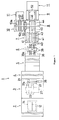
- Fig. 1 is a schematic plan view of a system for making printing plates for newspaper embodying the present invention.
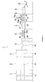
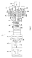
- Fig. 2 is a schematic side view of the system for making printing plates for newspaper.
- Fig. 3 is a schematic side and partly sectional view of the system for making printing plates for newspaper with the plate feeder, exposure unit, plate discharger and developer.
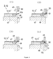
- Fig. 4 is drawings of the first bender and the second bender in the system for making printing plates for newspaper to explain the operation thereof.
- Fig. 5 is a diagram showing the process of making two printing plates each for two pages of newspaper from two plate materials each for two pages of newspaper.
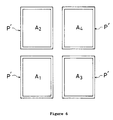
- Fig. 6 is a plan view of four printing plates, each the size of one page of newspaper.
- Fig. 7 is a diagram showing the process of making four printing plates, each the size of one page of newspaper, from two plate materials, each the size of two pages of newspaper.
- Fig. 8 is a schematic plan view of a system for making printing plates for newspaper according to another embodiment of the present invention.
- Fig. 9 is a plan view of two printing plates, each the size of two pages of newspaper.
- Fig. 10 is a plan view of four printing plates, each the size of two pages of newspaper.
- Fig. 1 is a schematic plan view of the system 1 of the present invention for making printing plates for newspaper by the CTP technique.
- the system 1 for making printing plates for newspaper includes a plate feeder 2, exposure unit 3, plate discharger 4, developer 5, direction changer 6, borer 7, cutter 8, first bender 9, second bender 10 and stacker 11.
- This system 1 can make in one process two pieces of printing plate P, each the size of two pages of newspaper, from two pieces of plate material 12, each having the size of two pages of newspaper arranged longitudinally in series, or four pieces of printing plate P', each the size of one page of newspaper, from two pieces of plate material 12, each the size of two pages of newspaper.
- two printing plates P, P each the size of two pages of newspaper, can be made simultaneously in the plate-making system 1.
- Two unexposed plate materials 12, 12, each the size of two pages of newspaper are supplied by the plate feeder 2 to the exposure unit 3 for image drawing.
- the two plate materials 12, 12 are then sent by the plate discharger 4 to the developer 5 for development.
- the plates 12, 12 are turned by the direction changer 6 and sent to the borer 7 where positioning notches 12a and holes 12b are formed in the two plate materials 12.
- the two plate materials 12, 12 are then referred to the first bender 9 without being cut where the plate materials are bent to form a bend 12c for mounting the plate on the cylinder of the rotary press (not shown). That way, two printing plates P, P, each the size of two pages of newspaper are made simultaneously.
- Four printing plates P' can be prepared this way.
- Two plate materials 12, 12 pass through the exposure unit 3, plate discharger 4, developer 5, direction changer 6 and borer 7 and are further supplied to the cutter 8 where the two plate materials 12 are each cut in the transverse direction at the centre in two pieces.
- the four plates 12' thus obtained and each having the size of one page of newspaper are then sent to the second bender 10 where the plates are each bent to form a bend 12c for mounting the plate on the cylinder of the rotary press, thereby simultaneously producing four printing plates P' each having the size of one page of newspaper.
- the sensitive plate that is used here is high-sensitive photopolymer plate made by coating an aluminum substrate with a high-sensitive photopolymer. These plates 12 as supplied are packed in the state that the plates 12 are piled up one upon another with a piece of protection paper between them to protect the plate surface (not shown).
- the apparatus such as the plate feeder 2, exposure unit 3, plate discharger 4, developer 5, direction changer 6, borer 7, cutter 8, first bender 9 and second bender 10 are automatically controlled according to preset signals from a control system (not shown) such as a computer.
- the plate feeder 2 is so designed to feed simultaneously two unexposed plate materials 12, 12, each the size of two pages of newspaper linked longitudinally in series, to the exposure unit 3.
- the plate feeder 2 comprises, as shown in Fig. 3, a frame 13; a dark box 14 with an openable lid 14b carried on the frame 13 and containing unexposed plate materials 12; a light-shielding metal cover 15 covering the whole of the frame 13 and having a door through which the dark box 14 is moved in and out; a lid closing mechanism provided on the frame 13 to open and close the lid 14b of the dark box 14; a protection paper remover 17 provided on the frame 13 to take out of the dark box 14 the plate-protective paper 12 sandwiched between the plate materials 12, 12 in the dark box 14; and a plate material carrier 18 provided on the side of the exposure unit 3 to suck and carry two plates 12, 12 out of the dark box 14 to the exposure unit 3 at a time.
- the plate feeder 2 operates this way: When the door of the light-shielding cover 15 is closed with the dark box 14 placed on the frame 13, the lid opening device 16 is actuated to leave the dark box 14 open and then the protection paper remover 17 will work to take out of the dark box 14 the plate-protective paper between the plates 12, 12 in the dark box 14. Then, the plate material carrier 18 is activated to suck and carry two plate materials out of the dark box 14 to the exposure unit 3.
- the dark box 14 as shown in Figs. 1 and 3, is made up of a box-shaped metal body 14a opened upward and storing piles of unexposed plate materials 12 placed side by side, and a metal lid 14b capable of opening and closing for covering the opening of the body 14a.
- the dark box is so designed that when the lid 14b is put on the body 14a, the lid 14 and the body 14a are fitted into each other so closely as to shield the dark box completely 14 from light.
- the lid closing mechanism 16 is formed out of a lifting body 16a arranged around the dark box 14 on the frame 13 allowed to go up and down, and engagable with the outer periphery of the lid 14b and a drive system to lift up and down the lifting body 16a.
- the lid closing 16 operates this way: when the lifting body 16a engaged with the outer periphery of the lid 14b is lifted, the lifting body 16a as indicated by a line including dots in Fig. 3 lifts the lid 14b to open the dark box 14. Reversely, if the lifting body 16a is lowered, the lid 14b is placed on the body 14a, closing the dark box 14 as indicated by solid line in Fig. 3.
- the protection paper remover 17 is made up of, as shown in Fig. 3, a plurality of vacuum-type suction cups 17a movable in the horizontal and vertical directions to suck and carry out of the dark box 14 the protection paper sandwiched between the plate materials 12 and 12 in the dark box 14 and a pair of paper discharging rollers 17b installed near the dark box 14 to discharge the paper conveyed by the suction cups 17a.
- the protection paper remover 17 is so designed that the protection paper on the unexposed plate material 12 in the dark box 14 is sucked up and moved to a position near the protection paper discharging rollers 17b, 17b, where part of the paper is engaged between the rotating rollers 17b and 17b so that the paper may be discharged out of the dark box 14.
- the protection paper carried out of the dark box 14 is discharged into a protection paper receiving bag (not shown) under the protection paper remover 17.
- the plate material carrier 18 comprises, as shown in Fig. 3, a two-stage expansion rail 18b which is provided at the ceiling portion of the space inside the exposure unit 3 and the plate discharger 4 and which is expanded and contracted by a fluid pressure cylinder 18a, a support frame 18d which is supported by the expansion rail 18b and allowed to run along the expansion rail 18b by the fluid pressure cylinder 18c and a header 18f which is mounted on the support frame 18C by means of a fluid pressure cylinder (not shown) allowed to move up and down and provided with a plurality of vacuum rubber suction cups 18e for holding the plate materials 12 in the dark box 14.
- the plate material carrier 18 operates this way: As the lid 14b of the dark box 14 is opened and the protection paper is removed, the expansion rail 18b stretches from the exposure unit 3 to the plate feeder 2 and the frame 18d moves to a position over the dark box 14. Then the header 18f moves down with the suction cups 18e sucking and holding a plate material 12 in the dark box 14. And the header 18f rises to raise two plate materials 12, 12 stored side by side in the body 14a of the dark box 14. In this state, the expansion rail 18b retracts into the exposure unit 3 and at the same time the support frame 18d moves to the exposure unit 3. Finally, the header 18f goes down to place the plate materials 12, 12 on the table of the exposure unit 3. Two plate materials 12, 12, each the size of two pages of newspaper, are fed to the exposure unit 3 simultaneously.
- the exposure unit 3 is mounted adjacent to and on the downstream side of the plate feeder 2 and exposes simultaneously two plate materials 12, 12, each the size of two pages of newspaper, fed by the plate feeder 2.
- the exposure unit 3 is formed out of, as shown in Figs. 1 and 3, a frame 19 provided adjacent to and downstream of the plate feeder 2.
- the frame 19 is provided with a table 20, exposure cylinder 21, plate winding roller 22, two laser scanning heads 23 and two cameras 24 for measurement of laser beam and others.
- the whole of the frame 19 is covered with a light-shielding metal cover 25 provided with a door that can open and close.
- the exposure unit 3 operates this way.
- Image drawing signals (digitized signals) for plate making from a computer (not shown) are sent to each laser scanning head 23 by way of a image drawing controller (not shown).
- Laser scanning is effected on the printing face of a high-sensitive photopolymer plate according to the image drawing signals.
- signal images are drawn in the form of latent images on the plate 12.
- the exposure cylinder 21 is driven to rotate by a servo motor 26.
- vacuum suction holes 21a which vacuum suck and hold the plate material on the surface of the exposure cylinder 21 and positioning stoppers (not shown) that position the upper end when the plate material 12 is mounted.
- the laser scanning heads 23 expose images directly on the sensitive plate 12 according to image drawing signals from the computer.
- the laser scanning heads 23 can be moved by the moving mechanism 27 of the exposure cylinder 21.
- the exposure unit 3 is of the same construction as that disclosed in the Japanese patent application laid open unexamined under No. 9-334320 etc.
- the two plate materials fed to the table 20 of the exposure unit 3 by the plate feeder 2 are positioned by the stoppers wherein the front end is put and held on the outside surface of the exposure cylinder 21 by the vacuum suction holes 21a and is wound on the outside surface of the exposure cylinder 21 as the exposure cylinder 21 and the plate winding roller 22 rotate in the winding direction. Then, the rear end is put and held on the outside surface of the exposure cylinder 21 by the vacuum suction holes 21a.
- the servo motor 26 rotates the exposure cylinder 21 in a specific direction.
- two laser scanning heads 23, 23 are moved in a specific direction by a moving mechanism 27, and image drawing (exposure) is done simultaneously on the two plates 12, 12 by the two laser scanning heads 23, 23.
- the plate discharger 4 is provided with, as shown in Fig. 3, a table 29, a belt conveyer 30 and others on a frame 28, which is installed downstream of and adjacent to the exposure unit 3. And the whole of the frame 28 is covered with a light-shielding metal cover 31 provided with a door that can be opened and closed.
- the plate discharger 4 is so constructed that the two exposed plate materials 12, 12 sent out from the exposure unit 3 are received by the table 29.
- the plate materials 12, 12 on the table 29 are referred to the developer 5 which follows by the belt conveyer 30.
- the developer 5 has within a case 32 a heater 33, developer 34, rinser 35, rubber coater 36 and dryer 37 as shown in Fig. 3.
- the latent image formed in the exposure unit 3 is heated by the heater 33 and fixed on the printing face on the plate and then the high sensitive photopolymer layer other than the fixed images is removed with alkaline solution to form a printing face.
- the plate material is then rinsed in the rinser 35 and put to protective treatment such as coating with rubber in the rubber coater 36.
- the direction changer 6 is mounted downstream of and adjacent to the developer 5. This direction changer 6 is to change the position of the plate material 12 so that the apparatuses which follow such as the borer 7 and cutter 8 may receive the plate material 12 properly.
- the direction changer 6 receives the two plate materials 12, 12 as discharged from the developer 5, and changes the direction of the plates by turning them 90 degrees before sending them out to the following borer 7.
- the direction changer 6 is formed out of a table 38 to receive the plate materials 12, 12 from the developer 5, a rotator 39 mounted over the table 38 movable up and down and rotatable and provided with vacuum suction cups 39a which hold two sensitive plates 12, 12 on the table 38 at a time and change the direction thereof, and a belt conveyer 40 provided on the table 38 to carry to the following borer 7 the turned two plate materials 12, 12.
- the borer 7 is also to make holes 12b used to position the plates on the first bender 9 and the second bender 10.
- the borer 7 as shown in Figs. 1 and 2 is a press machine with a plurality of punches (not shown) which is equipped with three vertically movable upper members 41 disposed side by side and positioned opposite to the two ends and the centre of the plate materials, and a lower member 42 provided with a plurality of holes (not shown) which fit with the punches of the upper members 41.
- the respective upper members 41 are moved up and down by a specific distance with the punches inserted into the corresponding holes on the lower member 42. This way, positioning notches 12a and holes 12b are formed at specific positions in the two plate materials 12.
- belt conveyers 43 which carry the two plate materials 12 to the cutter 8 which follows.
- the positioning notches 12a are formed at such places that positioning protrusions (not shown) provided on the plate cylinder of the rotary press may engage with those positioning notches 12a when the completed printing plate is mounted on the rotary press. That is, the positioning notches 12a are to put the printing plate in place on the plate cylinder and at the same time to block the printing plate from moving in the axial direction of the plate cylinder.
- the positioning holes 12b are formed at such places that the positioning pins 51 provided on the benders 9, 10 may engage with the corresponding holes 12b when the two ends of the plate materials 12 are bent by the first bender 9 and the second bender 10.
- the holes 12b are for the plate materials 12, 12 to be placed in a predetermined position on the benders 9, 10.
- the borer 7 makes notches 12a and holes 12b in the centre and at the two ends of the two plate materials 12, 12 as shown in Fig. 7 by moving up and down the three upper borer members 41.
- the two upper members 41 at the two ends move up and down to make notches 12a and holes 12b at the two ends as shown in Fig. 5.
- the cutter 8 is equipped with, as shown in Figs. 1 and 2, a loading platform 44 to receive and carry the two plate materials 12, 12 from the borer 7 and rotary blades 45 provided over the loading platform 44, movable vertically and allowed to run in the traverse direction of the plate 12. The rotary blades rotate and run to cut the plate materials 12.
- belt conveyers 46 On the loading platform 44 of the cutter 8 are provided belt conveyers 46 to send out the two plate materials 12, 12 to the following bender 9 in case the two plate materials 12, 12 are not cut in half.
- the cutter 8 is not actuated when there is no need to cut the two oblong plate materials, each the size of two pages of newspaper.
- the belt conveyers 46 alone work to send out the two oblong plates 12, 12 to the first bender 9.
- the first bender 9 is installed downstream of and adjacent to the cutter 8 as shown in Figs. 1 and 2.
- the first bender 9 forms bends 12c used when mounting the two uncut oblong plates 12, 12 on the plate cylinder of the rotary press.
- the second bender 10 is installed close to and on the lateral side of the cutter 8 as shown in Fig. 1.
- the second bender 10 forms bends 12c in four sensitive plates 12', each the size of one page of newspaper, which were produced by cutting in half the plates by the cutter 8.
- the bends 12c are used when the plates are mounted on the plate cylinder of the rotary press.
- the benders 9, 10 comprise, as shown in Fig. 4 (1) to (4): a loading platform 47 on which the plate 12 is put and which is somewhat longer than the plate material 12; receiving blades 48 provided at the two ends of the loading platform 47; a plate press 49 movable vertically in relation to the loading platform 47 to clamp the plate material on the loading platform 47; a bending movable blade 50 which is provided on the plate press 49 and pivotable to bend downward along the receiving blade 48 the edge portion of the plate material protruding beyond the receiving blade 48, which plate material 12 is pressed and clamped on the loading platform 47 by the plate press 49; and vertically movable positioning pins 51 which are provided outside of the receiving blade 48 and are to be fitted into the positioning holes 12b in the plate material 12.
- belt conveyers 52 to send out to the following stacker 11 the plate materials 12, 12' with bends 12c formed.
- the benders 9, 10 are of the same construction as those disclosed in the Japanese utility model application laid open under No. 53-159703.
- a moving means for transferring to the second bender 10 each one or two of the four plate materials 12', each the size of one page of newspaper, from the cutter 8.
- the moving means 53 includes, as shown in Figs. 1 and 2, a guide rail 53a provided above the cutter 8 and the second bender 10, a mover 53b mounted on the guide 53a, movable up and down and allowed to run along the guide rail 53a, and vacuum suction cups 53c that are mounted on the mover 53b and hold the plate materials 12' on the platform of the cutter 8 one by one or two by two. That is, it is so arranged that the plate materials 12' on the loading platform 44 of the cutter 8 can be transferred to the loading platform of the second bender 10 one by one or two by two.
- a dark room (not shown) provided separately from the plate-making system 1.
- piles of the plate materials 12 are stored side by side in the dark box.
- the dark box is then loaded on a handcart-type carrier (not shown) and moved through the daylight room to the plate feeder 2 of the plate-making system 1.
- the dark box 14 containing the plates are loaded on the frame 13 of the plate feeder 2.
- the door closing mechanism 16 is actuated to leave the dark box 14 opened and the protection paper remover 17 is actuated to remove out of the dark box 14 the protection paper protecting the printing face of plate materials 12 in the dark box 14 and discharge the same into a protection paper receiving bag (not shown). Then, the paper material carrier 18 works to suck and transfer two plate materials 12, 12 from the dark box 14 to the table 20 of the exposure unit 3.
- the two oblong plate materials 12, 12 carried to the exposure unit 3 are simultaneously put to image drawing treatment by the direct laser image drawing method.
- the exposed two plate materials 12, 12 are discharged by the plate discharger 4 from the exposure unit 3 to the developer 5 for development. That is, passing through the exposure unit 3 and the developer 5, the two plate materials 12, 12 of the size of two pages of newspaper are formed - one plate, having printing faces B1 and A2 and the other, having printing faces B2 and A4 (see Fig. 5 (1)).
- the two oblong plate materials 12, 12 discharged from the developer 5 are received by the direction changer 6 and held and turned 90 degrees by the rotator 39 and then sent out to the borer 7 by the belt conveyer 40 provided on the table 38 (see Fig. 5 (2)).
- the two plate materials 12, 12 sent to the borer 7 are bored. Thus formed are notches 12a at one end for positioning the plate 12 on the rotary press and also positioning holes 12b at the two ends for positioning the plate on the first bender 9. After that, the two sensitive plates 12, 12 are sent out to the cutter 8 by the belt conveyer 43 provided at the borer 7 (see Fig. 5 (3)).
- the two plate materials 12, 12 sent to the cutter 8 are not cut but forwarded to the first bend 9 by the belt conveyer 46 provided at the cutter 8.
- the two ends of each plate 12 are bent to form bends 12c for mounting the plate on the plate cylinder of the rotary press (see Fig. 5 (4)).
- a so-called printing plate P is a so-called printing plate P.
- Printing plates each the size of two pages of newspaper, are piled up and stored in the stacker 11 as they are sent in from the first bender 9 by the belt conveyer 52.
- a printing plate P of the size of two pages of newspaper having printing faces B1 and A2 and another printing plate P of the same size with printing faces B2 and A4 are made by the plate-making system 1.
- Those plates P are mounted on the plate cylinder of the rotary press for the printing of newspaper.
- printing face B1 or B2 on the printing plate P (Fig. 5 (4)) to be mounted on the plate cylinder of the rotary press has to be replaced with printing face A1 or A2.
- four one - page size printing plates P' having printing faces A1, A2, A3 and A4 as shown in Fig. 6 are made by the plate-making system 1 wherein the printing plate P mounted on the plate cylinder of the rotary press is replaced by one page size printing plates P'.
- the four printing plates P' or the four separate one-page printing faces - A1, A2, A3 and A4 - are prepared by the plate-making system 1 this way.
- two oblong plate materials 12, 12, each the size of two pages of newspaper, one with printing faces A1 and A2 and the other with printing faces A3 and A4 are produced.
- This process involves the plate feeder 2, exposure unit 3 and developer 5 as in making the aforesaid printing plate P.
- the plate material 12 with printing faces A1 and A2 and the plate material 12 with A3 and A4 are received by the direction changer 6 as they are discharged from the developer 5 and turned 90 degrees by the rotator 39. In that state, the plates are sent out to the borer 7 by the belt conveyer 40 provided on the table 38 (see Fig. 7 (2)).
- the two plate materials 12, 12 that are sent to the borer 7 are bored.
- the two sensitive plates 12, 12 are sent out to the cutter 8 by the belt conveyer 43 provided at the borer 7 (Fig. 7 (3)).
- the two plate materials 12, 12 which have been sent to the cutter 8 are cut along the traverse median line by the rotary blade 45 to give four separate plate materials 12', each with one of four printing faces - A1, A2, A3 and A4 (Fig. 7 (4)).
- the separated four plate materials 12' are then sent by the mover 53 one by one or two by two to the bender 10, where the two ends are bent to form bends 12C for mounting the plate on the plate cylinder of the rotary press (Fig. 7 (5)). That way, four separate one-page printing plates P'are prepared.
- this plate-making system it is possible to make, in one run of the process, to make four separate one-page printing plates P' each with one of four printing faces - A1, A2, A3 and A4. These printing plates P' are used for printing as replacement of the printing plate P mounted on the plate cylinder of the rotary press.
- the prior art plate-making system 1 has to conduct the plate-making process a plurality of times to prepare replacement printing plates P (oblong two-page plates) when a specific page on the printing plate P mounted on the plate cylinder of the rotary press was to be replaced with another.
- the plate-making system of the present invention can make, in one run of the process, replacement printing plate P' with great efficiency.
- Fig. 8 is a schematic plan view showing a system for making printing plates for newspaper by the CTP technique according to another embodiment of the present invention.
- this plate-making system there is provided the second bender 10 on each lateral side of the cutter 8 and, in addition, the stacker 11 downstream of each second bender 10 so that four separate one-page plate materials 12' from the cutter 8 are separated and supplied to the two units of the second bender 10 for bending.
- this embodiment is of the same arrangement as the plate-making system 1 illustrated in Figs. 1 to 4, including the same components: plate feeder 2, exposure unit 3, plate discharger 4, developer 5, direction changer 6, borer 7, cutter 8, first bender 9, second bender 10, moving means 53 and stacker 11.
- the plate material 12 is a high-sensitive photopolymer plate.
- other plates may be used which include silver salt plate, silver salt + diazo hybrid plate and heat-sensitive plate.
- two sensitive plates 12, 12, each the size of two pages of newspaper are cut into four one-page printing plate P'.
- a four-page plate material (not shown) may be cut into four one-page printing plate P'.
- the plate-making system 1 is a linear arrangement of plate feeder 2, exposure unit 3, plate discharger 4, developer 5, direction changer 6, borer 7, cutter 8 and first bender 9 with the second bender 10 placed on one side or two lateral sides of the cutter 8. That arrangement of the system components in the embodiments is not restrictive. Any arrangement or configuration may be adopted as long as the plate material 12, of the size of several pages of newspaper, can be processed and cut into one-page printing plates P'.
- a pack of unexposed plate material 12 is unpacked in a dark room (not shown) provided in a place separated from the plate-making system 1 and that the dark box containing the unpacked plate materials 12 is forwarded by a carrier cart to the plate-making system 1 through a daylight room.
- the dark box may be installed upstream of the plate-making system 1 so that the pack of unexposed plate materials 12 may be unpacked therein and sent to the plate feeder 2.
- the plate feeder is not limited to the described construction. Any construction or configuration will do as long as the plate feeder can supply unexposed plate materials 12 to the exposure unit 3.
- the direction changer 6 in the above embodiments comprises a rotator 39 equipped with suction cups 39a and a table 38 and so designed that the rotator 39 sucks and turns the sensitive plate 12 on the table 38.
- the direction changer 6 may comprise a turn table (not shown) which changes the direction of the plate material 12 and sends the same out to the borer 7 which follows.
- the cutter is provided with a movable rotary blade 45 which rotates and runs to cut plate material 12.
- a linear blade (not shown) may be used which is moved up and down to cut the plate material 12.
- a plate-making apparatus in accordance with the present invention may be provided, on the downstream side of the developer, with: a borer for forming positioning notches and positioning holes in the plate material discharged from the developer; a cutter for cutting the plate material, the size of several pages of newspapers from the borer into several plate materials, each the size of one page of newspaper; a first bender for forming bends for mounting the plate on the rotary press in the plate material having the size of several pages of newspaper, which has not been cut by the cutter; and a second bender for forming bends for mounting the plate on the rotary press in several one page size plate materials produced by cutting the plate materials by the cutter after the boring.
- the prior art plate-making system 1 had to conduct the plate-making process a plurality of times to prepare replacement printing plates P or oblong two-page plates.
- the plate-making system of the present invention can make, in one run of the process, four replacement printing plates, thus saving time and achieving great efficiency.
- the plate-making apparatus of the present invention may comprise a direction changer installed between the developer and the borer to change the direction or position of the plate material so as to make it easy for the plate material to be received and processed by the apparatuses which follow - the borer, cutter and benders.
- the apparatus of the present invention may be provided with a plurality of units of the second bender near the cutter so that a plurality of plate materials cut in the size of one page of newspaper are distributed among the benders for bending.
- a plurality of plate materials can be bent simultaneously, thus speeding up formation of bends and preparation of printing plate.
- the plate-making apparatus of the present invention may include a stacker installed on the downstream side of the first bender and the second bender 10 to pile up and store the prepared printing plates, which saves the trouble of sorting those pieces for easier handling.
Landscapes
- Exposure And Positioning Against Photoresist Photosensitive Materials (AREA)
- Manufacture Or Reproduction Of Printing Formes (AREA)
Abstract
A system for making printing plates for newspaper
which can make with great efficiency replacement printing
plates to be used when a printing face of the printing
plate mounted on the plate cylinder of the rotary press
is to be changed in part.
The plate-making system is so built by linearly
arranging a plate feeder 2, an exposure unit 3 and a
developer 5 that the exposure unit 3 may directly form
images on the printing faces of a plate material 12 in
accordance with the image drawing signals from the
computer to make a printing plate P large enough for at
least several pages, wherein there are provided on the
downstream side of the developer 5: a borer 7 for making
positioning notches 12a and positioning holes 12b in the
plate material 12 for several pages of newspaper as
discharged from the developer 5; a cutter 8 for cutting
the plate material 12 for several pages of newspaper from
the borer 7 into several plate materials 12, each the
size one page of newspaper; a first bender 9 for forming
bends 12c for mounting the printing plate on the rotary
press in the plate material 12 for several pages of
newspaper which has not been cut by the cutter 8 after
boring by the borer 7; and a second bender 10 for forming
bends 12c for mounting the printing plate on the rotary
press in several one page size plate materials 12' which
have been obtained by cutting the plate material by the
cutter 8 after boring by the borer 7.
Description
- The present invention relates to an improved system for making printing plates for newspaper printing by the computerised direct laser drawing technique.
- The recent progress of computer information and image-processing technologies has found its way into such fields as newspaper printing bringing about the development of a system for making printing plates for newspaper printing by the so-called CTP (computer to plate) technique. In this method, image signals from a computer activate a laser scanning head to draw desired images directly on a printing plate.
- Examples of this type of plate making system were developed by the inventors of the present invention and disclosed in the Japanese patent applications published unexamined under Nos. 9-66595 and 9-334320.
- Those plate-making systems are formed out of such apparatus as a plate feeder (plate feeding section), an exposure unit (electrostatic charge/drawing section), a plate discharging mechanism (plate discharging section) a development unit (heating, developing, rinsing, rubber coating and drying), a bending mechanism (bender) and a printing plate storing device (stacker) which are arranged in that order and can make printing plates in different sizes ranging from one page of a newspaper to several pages.
- Large-size printing plates made by such plate-making systems could save much time required to replace plates on the rotary press. That in turn could raise the rate of operation, thereby printing more pages of the newspaper.
- Meanwhile, newspaper report articles have been getting more and more locally diversified in contents in recent years, and advertisements have also been diversified, with newspapers now being printed in many different forms and editions. That has resulted in increased printing of local editions, newspapers having local news sections, that is, zoning newspapers, newspapers with pages suited for choice of readers (tailored newspapers), and newspapers with pages suited for choice of advertisers (targeted newspapers).
- In printing those newspapers, it often happens that articles (or contents) of a specific page in the newspaper have to be replaced. In conventional news printing, a printing plate wound around the plate cylinder of the rotary press has four or two pages. For replacement, in case a four-page plate is used, a whole plate having four pages has to be replaced with a new plate having four pages. If two plates, each for two pages, are mounted on a rotary press, then one plate of the two has to be replaced with a new one.
- To illustrate further, if a printing face B1 of a two-page printing plate P on a rotary press as shown in Fig. 9 is to be switched to printing face A1 or A3, or a printing face of B2 of a two page printing plate P is replaced with a printing face A1 or A3, then four printing plates P as shown in Fig. 10 are prepared for any of those changes so that the printing plate P mounted on the rotary press can be replaced by one of the four plates P shown in Fig. 10.
- In conventional plate-making systems, however, the maximum number of printing plates that can be produced by one operation of plate production is two two-page printing plates P. To make the four printing plates P as shown in Fig. 10, the plate-making process has to be repeated twice, requiring a long time for producing replacement printing plates P. In case a plurality of rotary presses are in operation, the number of printing plates P to be replaced will inevitably increase. That means that many new replacements have to be prepared. And now the time and cost required for making replacement printing plates P becomes a still more important problem.
- The present invention addresses those problems, and it is accordingly a primary object of the present invention to provide a plate-making system which can make replacement printing plates efficiently and economically when some changes are to be effected on part of the printing faces of the plates mounted on the cylinder of the rotary press.
- To achieve the foregoing object, the present invention provides a system for making printing plates for newspaper printing wherein a plate feeder, an exposure unit and a developer are linearly arranged, and the exposure unit may directly draw images on the printing faces of a plate material in accordance with image drawing signals from a computer to make a printing plate large enough for at least several pages; wherein there are provided on a downstream side of the developer: a borer for making positioning notches and positioning holes in the plate material for several pages of newspaper as discharged from the developer; a cutter for cutting the plate material for several pages of newspaper from the borer into several pieces of plate material, each the size of one page of newspaper; a first bender for forming bends, for mounting the printing plate on a rotary press, for several pages of newspaper which have not been cut by the cutter after boring by the borer; and a second bender for forming bends, for mounting the plate on the rotary press, in several one page pieces of plate material obtained by cutting plate material by the cutter after boring by the borer.
- Preferably, said system comprises a direction changer installed between the developer and the borer to change the direction of the plate material coming from the developer and send the plate material to the borer.
- Said system may comprise a plurality of second benders near the cutter so that several pieces of plate material cut in the size of one page of newspaper are distributed to the several benders for bending.
- Advantageously, the system may comprise a
stacker 11 installed on the downstream side of the first bender and the second bender to pile up and store the prepared printing plates P, P'. - Following is a description by way of example only with reference to the accompanying drawings of embodiments of the present invention.
- In the drawings:-
- Fig. 1 is a schematic plan view of a system for making printing plates for newspaper embodying the present invention.
- Fig. 2 is a schematic side view of the system for making printing plates for newspaper.
- Fig. 3 is a schematic side and partly sectional view of the system for making printing plates for newspaper with the plate feeder, exposure unit, plate discharger and developer.
- Fig. 4 is drawings of the first bender and the second bender in the system for making printing plates for newspaper to explain the operation thereof.
- Fig. 5 is a diagram showing the process of making two printing plates each for two pages of newspaper from two plate materials each for two pages of newspaper.
- Fig. 6 is a plan view of four printing plates, each the size of one page of newspaper.
- Fig. 7 is a diagram showing the process of making four printing plates, each the size of one page of newspaper, from two plate materials, each the size of two pages of newspaper.
- Fig. 8 is a schematic plan view of a system for making printing plates for newspaper according to another embodiment of the present invention.
- Fig. 9 is a plan view of two printing plates, each the size of two pages of newspaper.
- Fig. 10 is a plan view of four printing plates, each the size of two pages of newspaper.
- Fig. 1 is a schematic plan view of the
system 1 of the present invention for making printing plates for newspaper by the CTP technique. Thesystem 1 for making printing plates for newspaper includes aplate feeder 2,exposure unit 3,plate discharger 4,developer 5,direction changer 6, borer 7,cutter 8,first bender 9,second bender 10 andstacker 11. Thissystem 1 can make in one process two pieces of printing plate P, each the size of two pages of newspaper, from two pieces ofplate material 12, each having the size of two pages of newspaper arranged longitudinally in series, or four pieces of printing plate P', each the size of one page of newspaper, from two pieces ofplate material 12, each the size of two pages of newspaper. - To illustrate, two printing plates P, P , each the size of two pages of newspaper, can be made simultaneously in the plate-
making system 1. Twounexposed plate materials plate feeder 2 to theexposure unit 3 for image drawing. The twoplate materials plate discharger 4 to thedeveloper 5 for development. After that, theplates direction changer 6 and sent to the borer 7 where positioningnotches 12a andholes 12b are formed in the twoplate materials 12. The twoplate materials first bender 9 without being cut where the plate materials are bent to form abend 12c for mounting the plate on the cylinder of the rotary press (not shown). That way, two printing plates P, P, each the size of two pages of newspaper are made simultaneously. - Four printing plates P' can be prepared this way. Two
plate materials exposure unit 3,plate discharger 4,developer 5,direction changer 6 and borer 7 and are further supplied to thecutter 8 where the twoplate materials 12 are each cut in the transverse direction at the centre in two pieces. The four plates 12' thus obtained and each having the size of one page of newspaper are then sent to thesecond bender 10 where the plates are each bent to form abend 12c for mounting the plate on the cylinder of the rotary press, thereby simultaneously producing four printing plates P' each having the size of one page of newspaper. - The sensitive plate that is used here is high-sensitive photopolymer plate made by coating an aluminum substrate with a high-sensitive photopolymer. These
plates 12 as supplied are packed in the state that theplates 12 are piled up one upon another with a piece of protection paper between them to protect the plate surface (not shown). - It is also noted that the apparatus such as the
plate feeder 2,exposure unit 3,plate discharger 4,developer 5,direction changer 6, borer 7,cutter 8,first bender 9 andsecond bender 10 are automatically controlled according to preset signals from a control system (not shown) such as a computer. - The
plate feeder 2 is so designed to feed simultaneously twounexposed plate materials exposure unit 3. - The
plate feeder 2 comprises, as shown in Fig. 3, aframe 13; adark box 14 with anopenable lid 14b carried on theframe 13 and containingunexposed plate materials 12; a light-shielding metal cover 15 covering the whole of theframe 13 and having a door through which thedark box 14 is moved in and out; a lid closing mechanism provided on theframe 13 to open and close thelid 14b of thedark box 14; aprotection paper remover 17 provided on theframe 13 to take out of thedark box 14 the plate-protective paper 12 sandwiched between theplate materials dark box 14; and aplate material carrier 18 provided on the side of theexposure unit 3 to suck and carry twoplates dark box 14 to theexposure unit 3 at a time. Theplate feeder 2 operates this way: When the door of the light-shielding cover 15 is closed with thedark box 14 placed on theframe 13, thelid opening device 16 is actuated to leave thedark box 14 open and then theprotection paper remover 17 will work to take out of thedark box 14 the plate-protective paper between theplates dark box 14. Then, theplate material carrier 18 is activated to suck and carry two plate materials out of thedark box 14 to theexposure unit 3. - The
dark box 14, as shown in Figs. 1 and 3, is made up of a box-shaped metal body 14a opened upward and storing piles ofunexposed plate materials 12 placed side by side, and ametal lid 14b capable of opening and closing for covering the opening of thebody 14a. The dark box is so designed that when thelid 14b is put on thebody 14a, thelid 14 and thebody 14a are fitted into each other so closely as to shield the dark box completely 14 from light. - The
lid closing mechanism 16 is formed out of alifting body 16a arranged around thedark box 14 on theframe 13 allowed to go up and down, and engagable with the outer periphery of thelid 14b and a drive system to lift up and down thelifting body 16a. Thelid closing 16 operates this way: when thelifting body 16a engaged with the outer periphery of thelid 14b is lifted, thelifting body 16a as indicated by a line including dots in Fig. 3 lifts thelid 14b to open thedark box 14. Reversely, if thelifting body 16a is lowered, thelid 14b is placed on thebody 14a, closing thedark box 14 as indicated by solid line in Fig. 3. - The
protection paper remover 17 is made up of, as shown in Fig. 3, a plurality of vacuum-type suction cups 17a movable in the horizontal and vertical directions to suck and carry out of thedark box 14 the protection paper sandwiched between theplate materials dark box 14 and a pair ofpaper discharging rollers 17b installed near thedark box 14 to discharge the paper conveyed by thesuction cups 17a. Theprotection paper remover 17 is so designed that the protection paper on theunexposed plate material 12 in thedark box 14 is sucked up and moved to a position near the protectionpaper discharging rollers rotating rollers dark box 14. - The protection paper carried out of the
dark box 14 is discharged into a protection paper receiving bag (not shown) under theprotection paper remover 17. - The
plate material carrier 18 comprises, as shown in Fig. 3, a two-stage expansion rail 18b which is provided at the ceiling portion of the space inside theexposure unit 3 and theplate discharger 4 and which is expanded and contracted by afluid pressure cylinder 18a, asupport frame 18d which is supported by theexpansion rail 18b and allowed to run along theexpansion rail 18b by thefluid pressure cylinder 18c and aheader 18f which is mounted on the support frame 18C by means of a fluid pressure cylinder (not shown) allowed to move up and down and provided with a plurality of vacuumrubber suction cups 18e for holding theplate materials 12 in thedark box 14. Theplate material carrier 18 operates this way: As thelid 14b of thedark box 14 is opened and the protection paper is removed, theexpansion rail 18b stretches from theexposure unit 3 to theplate feeder 2 and theframe 18d moves to a position over thedark box 14. Then theheader 18f moves down with thesuction cups 18e sucking and holding aplate material 12 in thedark box 14. And theheader 18f rises to raise twoplate materials body 14a of thedark box 14. In this state, theexpansion rail 18b retracts into theexposure unit 3 and at the same time thesupport frame 18d moves to theexposure unit 3. Finally, theheader 18f goes down to place theplate materials exposure unit 3. Twoplate materials exposure unit 3 simultaneously. - The
exposure unit 3 is mounted adjacent to and on the downstream side of theplate feeder 2 and exposes simultaneously twoplate materials plate feeder 2. - To further illustrate, the
exposure unit 3 is formed out of, as shown in Figs. 1 and 3, aframe 19 provided adjacent to and downstream of theplate feeder 2. Theframe 19 is provided with a table 20,exposure cylinder 21,plate winding roller 22, two laser scanning heads 23 and twocameras 24 for measurement of laser beam and others. The whole of theframe 19 is covered with a light-shieldingmetal cover 25 provided with a door that can open and close. Theexposure unit 3 operates this way. Image drawing signals (digitized signals) for plate making from a computer (not shown) are sent to eachlaser scanning head 23 by way of a image drawing controller (not shown). Laser scanning is effected on the printing face of a high-sensitive photopolymer plate according to the image drawing signals. Thus, signal images are drawn in the form of latent images on theplate 12. - The
exposure cylinder 21 is driven to rotate by aservo motor 26. On the outside surface are providedvacuum suction holes 21a which vacuum suck and hold the plate material on the surface of theexposure cylinder 21 and positioning stoppers (not shown) that position the upper end when theplate material 12 is mounted. - Furthermore, the laser scanning heads 23 expose images directly on the
sensitive plate 12 according to image drawing signals from the computer. The laser scanning heads 23 can be moved by the movingmechanism 27 of theexposure cylinder 21. - The
exposure unit 3 is of the same construction as that disclosed in the Japanese patent application laid open unexamined under No. 9-334320 etc. - Thus, the two plate materials fed to the table 20 of the
exposure unit 3 by theplate feeder 2 are positioned by the stoppers wherein the front end is put and held on the outside surface of theexposure cylinder 21 by thevacuum suction holes 21a and is wound on the outside surface of theexposure cylinder 21 as theexposure cylinder 21 and theplate winding roller 22 rotate in the winding direction. Then, the rear end is put and held on the outside surface of theexposure cylinder 21 by thevacuum suction holes 21a. - When the two
plate materials exposure cylinder 21, theservo motor 26 rotates theexposure cylinder 21 in a specific direction. At the same time, two laser scanning heads 23, 23 are moved in a specific direction by a movingmechanism 27, and image drawing (exposure) is done simultaneously on the twoplates - When image drawing is completed on the two
plates 12, the front end of theplate 12 held by thevacuum suction holes 21a is released, and theexposure cylinder 21 and theplate winding roller 22 rotate in a specific direction. By this action, the twoplate materials exposure cylinder 21 are removed and carried away to theplate discharger 4. - The
plate discharger 4 is provided with, as shown in Fig. 3, a table 29, abelt conveyer 30 and others on aframe 28, which is installed downstream of and adjacent to theexposure unit 3. And the whole of theframe 28 is covered with a light-shieldingmetal cover 31 provided with a door that can be opened and closed. Theplate discharger 4 is so constructed that the two exposedplate materials exposure unit 3 are received by the table 29. Theplate materials developer 5 which follows by thebelt conveyer 30. - The
developer 5 has within a case 32 aheater 33,developer 34,rinser 35,rubber coater 36 anddryer 37 as shown in Fig. 3. In thisunit 5, the latent image formed in theexposure unit 3 is heated by theheater 33 and fixed on the printing face on the plate and then the high sensitive photopolymer layer other than the fixed images is removed with alkaline solution to form a printing face. The plate material is then rinsed in therinser 35 and put to protective treatment such as coating with rubber in therubber coater 36. - The
direction changer 6 is mounted downstream of and adjacent to thedeveloper 5. Thisdirection changer 6 is to change the position of theplate material 12 so that the apparatuses which follow such as the borer 7 andcutter 8 may receive theplate material 12 properly. - To further illustrate, the
direction changer 6 receives the twoplate materials developer 5, and changes the direction of the plates by turning them 90 degrees before sending them out to the following borer 7. As shown in Figs. 1 and 2, thedirection changer 6 is formed out of a table 38 to receive theplate materials developer 5, arotator 39 mounted over the table 38 movable up and down and rotatable and provided withvacuum suction cups 39a which hold twosensitive plates belt conveyer 40 provided on the table 38 to carry to the following borer 7 the turned twoplate materials - The borer 7, which is provided downstream of and adjacent to the
direction changer 6, is to form in the twoplate materials direction changer 6positioning notches 12a used to position the printing plate on the rotary press . The borer 7 is also to makeholes 12b used to position the plates on thefirst bender 9 and thesecond bender 10. - The borer 7 as shown in Figs. 1 and 2 is a press machine with a plurality of punches (not shown) which is equipped with three vertically movable
upper members 41 disposed side by side and positioned opposite to the two ends and the centre of the plate materials, and alower member 42 provided with a plurality of holes (not shown) which fit with the punches of theupper members 41. In operation, the respectiveupper members 41 are moved up and down by a specific distance with the punches inserted into the corresponding holes on thelower member 42. This way,positioning notches 12a and holes 12b are formed at specific positions in the twoplate materials 12. - On the
lower member 42 of the borer 7 are providedbelt conveyers 43 which carry the twoplate materials 12 to thecutter 8 which follows. - The
positioning notches 12a are formed at such places that positioning protrusions (not shown) provided on the plate cylinder of the rotary press may engage with those positioningnotches 12a when the completed printing plate is mounted on the rotary press. That is, thepositioning notches 12a are to put the printing plate in place on the plate cylinder and at the same time to block the printing plate from moving in the axial direction of the plate cylinder. - The positioning holes 12b are formed at such places that the positioning pins 51 provided on the
benders holes 12b when the two ends of theplate materials 12 are bent by thefirst bender 9 and thesecond bender 10. In other words, theholes 12b are for theplate materials benders - Thus, when the two
plate materials 12 are to be cut along the width-wise median line into four plate materials 12', the borer 7 makesnotches 12a and holes 12b in the centre and at the two ends of the twoplate materials upper borer members 41. On the other hand, where there is no need to cut the twoplate materials 12 in half by thecutter 8, only the twoupper members 41 at the two ends move up and down to makenotches 12a and holes 12b at the two ends as shown in Fig. 5. -
Square notches 12a made in the centre of theplates notches 12a when theplates cutter 8. - The
cutter 8, mounted downstream of and adjacent to the borer 7, cuts in half the twoplate materials - The
cutter 8 is equipped with, as shown in Figs. 1 and 2, aloading platform 44 to receive and carry the twoplate materials rotary blades 45 provided over theloading platform 44, movable vertically and allowed to run in the traverse direction of theplate 12. The rotary blades rotate and run to cut theplate materials 12. - On the
loading platform 44 of thecutter 8 are providedbelt conveyers 46 to send out the twoplate materials following bender 9 in case the twoplate materials - The
cutter 8 is not actuated when there is no need to cut the two oblong plate materials, each the size of two pages of newspaper. Thebelt conveyers 46 alone work to send out the twooblong plates first bender 9. - The
first bender 9 is installed downstream of and adjacent to thecutter 8 as shown in Figs. 1 and 2. Thefirst bender 9 forms bends 12c used when mounting the two uncutoblong plates second bender 10 is installed close to and on the lateral side of thecutter 8 as shown in Fig. 1. Thesecond bender 10 forms bends 12c in four sensitive plates 12', each the size of one page of newspaper, which were produced by cutting in half the plates by thecutter 8. Thebends 12c are used when the plates are mounted on the plate cylinder of the rotary press. - The
benders loading platform 47 on which theplate 12 is put and which is somewhat longer than theplate material 12; receivingblades 48 provided at the two ends of theloading platform 47; aplate press 49 movable vertically in relation to theloading platform 47 to clamp the plate material on theloading platform 47; a bendingmovable blade 50 which is provided on theplate press 49 and pivotable to bend downward along the receivingblade 48 the edge portion of the plate material protruding beyond the receivingblade 48, whichplate material 12 is pressed and clamped on theloading platform 47 by theplate press 49; and vertically movable positioning pins 51 which are provided outside of the receivingblade 48 and are to be fitted into the positioning holes 12b in theplate material 12. By thosebends plate material 12 are bent until a roughly V-shapedbend 12c is formed. - On the
loading platform 47 of the first andsecond benders belt conveyers 52 to send out to the followingstacker 11 theplate materials 12, 12' withbends 12c formed. - The
benders - Above the
cutter 8 and thesecond bender 10 is a moving means for transferring to thesecond bender 10 each one or two of the four plate materials 12', each the size of one page of newspaper, from thecutter 8. - The moving means 53 includes, as shown in Figs. 1 and 2, a
guide rail 53a provided above thecutter 8 and thesecond bender 10, amover 53b mounted on theguide 53a, movable up and down and allowed to run along theguide rail 53a, andvacuum suction cups 53c that are mounted on themover 53b and hold the plate materials 12' on the platform of thecutter 8 one by one or two by two. That is, it is so arranged that the plate materials 12' on theloading platform 44 of thecutter 8 can be transferred to the loading platform of thesecond bender 10 one by one or two by two. - The
stackers 11, each provided downstream of and adjacent to thefirst bend 9 and thesecond bender 10, store piles of theplate materials 12, 12' (printing plates P, P') conveyed from thebenders - There will now be described examples of making an oblong printing plate P, the size of two pages of newspaper, having printing face B1 and A2, and another oblong printing plate P, the size of two pages of newspaper, having printing face B2 and A4.
- A pack of oblong
unexposed plate materials 12, each the size of two pages of newspaper, is unpacked in a dark room (not shown) provided separately from the plate-makingsystem 1. In this dark room, piles of theplate materials 12 are stored side by side in the dark box. The dark box is then loaded on a handcart-type carrier (not shown) and moved through the daylight room to theplate feeder 2 of the plate-makingsystem 1. Thedark box 14 containing the plates are loaded on theframe 13 of theplate feeder 2. - When the door of the light-shielding
cover 15 is closed with thedark box 14 placed on theframe 13 of theplate feeder 2, thedoor closing mechanism 16 is actuated to leave thedark box 14 opened and theprotection paper remover 17 is actuated to remove out of thedark box 14 the protection paper protecting the printing face ofplate materials 12 in thedark box 14 and discharge the same into a protection paper receiving bag (not shown). Then, thepaper material carrier 18 works to suck and transfer twoplate materials dark box 14 to the table 20 of theexposure unit 3. - The two
oblong plate materials exposure unit 3 are simultaneously put to image drawing treatment by the direct laser image drawing method. The exposed twoplate materials plate discharger 4 from theexposure unit 3 to thedeveloper 5 for development. That is, passing through theexposure unit 3 and thedeveloper 5, the twoplate materials - The two
oblong plate materials developer 5 are received by thedirection changer 6 and held and turned 90 degrees by therotator 39 and then sent out to the borer 7 by thebelt conveyer 40 provided on the table 38 (see Fig. 5 (2)). - The two
plate materials notches 12a at one end for positioning theplate 12 on the rotary press and also positioningholes 12b at the two ends for positioning the plate on thefirst bender 9. After that, the twosensitive plates cutter 8 by thebelt conveyer 43 provided at the borer 7 (see Fig. 5 (3)). - The two
plate materials cutter 8 are not cut but forwarded to thefirst bend 9 by thebelt conveyer 46 provided at thecutter 8. At thebender 9, the two ends of eachplate 12 are bent to formbends 12c for mounting the plate on the plate cylinder of the rotary press (see Fig. 5 (4)). Thus obtained is a so-called printing plate P. - Printing plates, each the size of two pages of newspaper, are piled up and stored in the
stacker 11 as they are sent in from thefirst bender 9 by thebelt conveyer 52. - That way, a printing plate P of the size of two pages of newspaper having printing faces B1 and A2 and another printing plate P of the same size with printing faces B2 and A4 are made by the plate-making
system 1. Those plates P are mounted on the plate cylinder of the rotary press for the printing of newspaper. - Meanwhile, it can happen that printing face B1 or B2 on the printing plate P (Fig. 5 (4)) to be mounted on the plate cylinder of the rotary press has to be replaced with printing face A1 or A2. In such a case, four one - page size printing plates P' having printing faces A1, A2, A3 and A4 as shown in Fig. 6 are made by the plate-making
system 1 wherein the printing plate P mounted on the plate cylinder of the rotary press is replaced by one page size printing plates P'. - The four printing plates P' or the four separate one-page printing faces - A1, A2, A3 and A4 - are prepared by the plate-making
system 1 this way. First, twooblong plate materials plate feeder 2,exposure unit 3 anddeveloper 5 as in making the aforesaid printing plate P. - The
plate material 12 with printing faces A1 and A2 and theplate material 12 with A3 and A4 are received by thedirection changer 6 as they are discharged from thedeveloper 5 and turned 90 degrees by therotator 39. In that state, the plates are sent out to the borer 7 by thebelt conveyer 40 provided on the table 38 (see Fig. 7 (2)). - The two
plate materials notches 12a at one end and in the centre for positioning theplate 12 on the rotary press and also positioningholes 12b at the two ends and in the centre for positioning the plate on thesecond bender 10. After boring, the twosensitive plates cutter 8 by thebelt conveyer 43 provided at the borer 7 (Fig. 7 (3)). - The two
plate materials cutter 8 are cut along the traverse median line by therotary blade 45 to give four separate plate materials 12', each with one of four printing faces - A1, A2, A3 and A4 (Fig. 7 (4)). - The separated four plate materials 12' are then sent by the
mover 53 one by one or two by two to thebender 10, where the two ends are bent to formbends 12C for mounting the plate on the plate cylinder of the rotary press (Fig. 7 (5)). That way, four separate one-page printing plates P'are prepared. - Separate one-page printing plates P' are piled up and stored in the
stacker 11 as they are sent out on thebelt conveyer 52 from thesecond bender 10. - By this plate-making
system 1, as set forth above, it is possible to make, in one run of the process, to make four separate one-page printing plates P' each with one of four printing faces - A1, A2, A3 and A4. These printing plates P' are used for printing as replacement of the printing plate P mounted on the plate cylinder of the rotary press. - The prior art plate-making
system 1 has to conduct the plate-making process a plurality of times to prepare replacement printing plates P (oblong two-page plates) when a specific page on the printing plate P mounted on the plate cylinder of the rotary press was to be replaced with another. The plate-making system of the present invention can make, in one run of the process, replacement printing plate P' with great efficiency. - Fig. 8 is a schematic plan view showing a system for making printing plates for newspaper by the CTP technique according to another embodiment of the present invention. In this plate-making system, there is provided the
second bender 10 on each lateral side of thecutter 8 and, in addition, thestacker 11 downstream of eachsecond bender 10 so that four separate one-page plate materials 12' from thecutter 8 are separated and supplied to the two units of thesecond bender 10 for bending. - Except for that, this embodiment is of the same arrangement as the plate-making
system 1 illustrated in Figs. 1 to 4, including the same components:plate feeder 2,exposure unit 3,plate discharger 4,developer 5,direction changer 6, borer 7,cutter 8,first bender 9,second bender 10, moving means 53 andstacker 11. - The parts of this embodiment common with those of the system in Fig. 1 are to be shown by the same reference numerals. No detailed description will be given.
- In the plate-making
system 1 of this embodiment of the present invention, it is possible to formbends 12c in the four separate printing plates 12' by the two units ofsecond bender 10. In other words, replacement printing plates P' can be prepared in a shorter time. - In the preceding embodiments, the
plate material 12 is a high-sensitive photopolymer plate. In another embodiment, other plates may be used which include silver salt plate, silver salt + diazo hybrid plate and heat-sensitive plate. - In the embodiments described above, two
sensitive plates - In those embodiments just described, the plate-making
system 1 is a linear arrangement ofplate feeder 2,exposure unit 3,plate discharger 4,developer 5,direction changer 6, borer 7,cutter 8 andfirst bender 9 with thesecond bender 10 placed on one side or two lateral sides of thecutter 8. That arrangement of the system components in the embodiments is not restrictive. Any arrangement or configuration may be adopted as long as theplate material 12, of the size of several pages of newspaper, can be processed and cut into one-page printing plates P'. - It is also so arranged in the embodiments described above that a pack of
unexposed plate material 12 is unpacked in a dark room (not shown) provided in a place separated from the plate-makingsystem 1 and that the dark box containing the unpackedplate materials 12 is forwarded by a carrier cart to the plate-makingsystem 1 through a daylight room. In another embodiment, the dark box may be installed upstream of the plate-makingsystem 1 so that the pack ofunexposed plate materials 12 may be unpacked therein and sent to theplate feeder 2. - The plate feeder is not limited to the described construction. Any construction or configuration will do as long as the plate feeder can supply
unexposed plate materials 12 to theexposure unit 3. - The
direction changer 6 in the above embodiments comprises arotator 39 equipped withsuction cups 39a and a table 38 and so designed that therotator 39 sucks and turns thesensitive plate 12 on the table 38. In another embodiment, thedirection changer 6 may comprise a turn table (not shown) which changes the direction of theplate material 12 and sends the same out to the borer 7 which follows. - In the aforesaid embodiments, the cutter is provided with a
movable rotary blade 45 which rotates and runs to cutplate material 12. In another embodiment, instead of the rotary blade 45a, a linear blade (not shown) may be used which is moved up and down to cut theplate material 12. - As set forth above, a plate-making apparatus in accordance with the present invention may be provided, on the downstream side of the developer, with: a borer for forming positioning notches and positioning holes in the plate material discharged from the developer; a cutter for cutting the plate material, the size of several pages of newspapers from the borer into several plate materials, each the size of one page of newspaper; a first bender for forming bends for mounting the plate on the rotary press in the plate material having the size of several pages of newspaper, which has not been cut by the cutter; and a second bender for forming bends for mounting the plate on the rotary press in several one page size plate materials produced by cutting the plate materials by the cutter after the boring.
- That facilitates replacement of a page or pages on the printing plate of the several page size on the rotary press. The prior art plate-making
system 1 had to conduct the plate-making process a plurality of times to prepare replacement printing plates P or oblong two-page plates. The plate-making system of the present invention can make, in one run of the process, four replacement printing plates, thus saving time and achieving great efficiency. - The plate-making apparatus of the present invention may comprise a direction changer installed between the developer and the borer to change the direction or position of the plate material so as to make it easy for the plate material to be received and processed by the apparatuses which follow - the borer, cutter and benders.
- The apparatus of the present invention may be provided with a plurality of units of the second bender near the cutter so that a plurality of plate materials cut in the size of one page of newspaper are distributed among the benders for bending. In other words, a plurality of plate materials can be bent simultaneously, thus speeding up formation of bends and preparation of printing plate.
- The plate-making apparatus of the present invention may include a stacker installed on the downstream side of the first bender and the
second bender 10 to pile up and store the prepared printing plates, which saves the trouble of sorting those pieces for easier handling.
Claims (11)
- Apparatus for producing single-page and multiple-page printing plates adapted for mounting on a rotary press cylinder; which apparatus comprises:plate feeding means for feeding unexposed printing plates into the apparatus;exposing and developing means for recording on each of said unexposed plates images for two or more pages, so as to produce a multiple-page printing plate;means for cutting selected multiple-page printing plates into a plurality of single-page plates;first bending means adapted to bend each of said single-page printing plates so as to configure each single-page plate for correct mounting on a rotary press cylinder;second bending means adapted to bend each uncut multiple-page printing plate so as to configure the plate for correct mounting on a rotary press cylinder; andconveying means adapted for conveying said uncut plates to the second bending means and said cut plates to the first bending means.
- Apparatus as claimed in claim 1, characterised in that said cutting means is selectively operable to cut selected multiple-page printing plates into a plurality of cut plates, and said conveying means comprises a first conveyor adapted to convey said cut plates from the cutting means to the first bending means and a second conveyor adapted to convey said uncut plates from the cutting means to the second bending means.
- Apparatus as claimed in claim 1, wherein said conveying means includes a first conveyor adapted to convey selected multiple-page printing plates to the cutting means for cutting, and a second conveyor adapted to convey the remaining multiple-page printing plates to the second bending means for bending.
- Apparatus as claimed in claim 2, wherein said first or second conveyor comprises a guide rail extending from the cutting means to the first or second bending means, and a plate carrier slidably mounted on said guide rail and adapted to move on the rail between said cutting means and said first or second bending means, which plate carrier is adapted to carry one or more plates from the cutting means to the first or second bending means.
- Apparatus as claimed in claim 4, wherein said plate carrier comprises one or more vacuum suction cups for holding said one or more plates.
- Apparatus as claimed in any preceding claim, wherein said cutting means comprises one or more rotary blades.
- Apparatus as claimed in any preceding claim, further comprising perforating means for forming notches or apertures in each of said printing plates, so as to enable said printing plates to be correctly mounted on the first or second bending means for bending, and/or to enable said printing plates to be correctly positioned on a rotary press cylinder.
- Apparatus as claimed in any preceding claim, characterised in that said first bending means comprises a plurality of benders adapted for simultaneously bending a plurality of cut printing plates.
- Apparatus as claimed in any preceding claim, further comprising stacking means for stacking said cut and/or uncut printing plates when said plates emerge from the first and/or second bending means.
- Apparatus as claimed in any preceding claim, characterised in that said exposing and developing means comprises one or more laser scanning heads arranged for producing an image on said unexposed printing plates.
- Use of the apparatus of any of claims 1-10 for preparing multiple-page and/or single-page printing plates for printing newspaper pages, magazine pages, and the like.
Applications Claiming Priority (2)
| Application Number | Priority Date | Filing Date | Title |
|---|---|---|---|
| JP25492898 | 1998-09-09 | ||
| JP10254928A JP3007077B1 (en) | 1998-09-09 | 1998-09-09 | Plate making equipment for newspaper printing |
Publications (1)
| Publication Number | Publication Date |
|---|---|
| EP0985528A1 true EP0985528A1 (en) | 2000-03-15 |
Family
ID=17271816
Family Applications (1)
| Application Number | Title | Priority Date | Filing Date |
|---|---|---|---|
| EP99307161A Withdrawn EP0985528A1 (en) | 1998-09-09 | 1999-09-09 | Improvements in and relating to the manufacture of printing plates |
Country Status (4)
| Country | Link |
|---|---|
| US (1) | US6076464A (en) |
| EP (1) | EP0985528A1 (en) |
| JP (1) | JP3007077B1 (en) |
| CA (1) | CA2281996A1 (en) |
Cited By (4)
| Publication number | Priority date | Publication date | Assignee | Title |
|---|---|---|---|---|
| US7225737B2 (en) | 2003-12-09 | 2007-06-05 | Kodak Graphic Communications Canada Company | Method for automated platemaking |
| EP2033927A1 (en) | 2006-06-30 | 2009-03-11 | Otis Elevator Company | Elevator having a shallow pit and/or a low overhead |
| DE102008043840B3 (en) * | 2008-11-19 | 2010-03-04 | Koenig & Bauer Aktiengesellschaft | Method for operating printing block at pressure unit, involves mounting printing plate in storage unit, where hanging limbs are formed at printing plate after their intermediate mounting in another storage unit |
| EP4563352A1 (en) | 2023-11-30 | 2025-06-04 | Heidelberger Druckmaschinen AG | Installation for providing exposed and bent printing plates |
Families Citing this family (23)
| Publication number | Priority date | Publication date | Assignee | Title |
|---|---|---|---|---|
| DE19743819A1 (en) * | 1997-10-05 | 1999-04-08 | Heidelberger Druckmasch Ag | Control panel for a printing press |
| JP3708716B2 (en) * | 1998-08-04 | 2005-10-19 | 大日本スクリーン製造株式会社 | Drawing device |
| JP3190956B2 (en) * | 1998-11-02 | 2001-07-23 | 株式会社金田機械製作所 | Manufacturing method of printing plate for newspaper printing |
| JP3795258B2 (en) | 1999-06-17 | 2006-07-12 | 富士写真フイルム株式会社 | Planographic printing plate processing apparatus and planographic printing plate processing method |
| US6318262B1 (en) * | 2000-02-25 | 2001-11-20 | Agfa Corporation | External drum imaging system |
| US6295929B1 (en) * | 2000-02-25 | 2001-10-02 | Agfa Corporation | External drum imaging system |
| JP4343386B2 (en) * | 2000-03-17 | 2009-10-14 | 富士フイルム株式会社 | Printing plate automatic exposure system |
| US6354208B1 (en) * | 2000-05-15 | 2002-03-12 | Agfa Corporation | Plate handling method and apparatus for imaging system |
| JP3407112B2 (en) * | 2000-10-30 | 2003-05-19 | 株式会社東京機械製作所 | Plate mounting position determination device |
| US20030031493A1 (en) * | 2001-08-07 | 2003-02-13 | Hendrik Frank | Printing/image-setting system |
| JP3714894B2 (en) * | 2001-09-13 | 2005-11-09 | 大日本スクリーン製造株式会社 | Image recording apparatus and image recording system including image recording apparatus |
| US6772691B2 (en) * | 2002-08-29 | 2004-08-10 | Agfa Corporation | System and method for registering media in an imaging system |
| US6899030B2 (en) * | 2003-05-05 | 2005-05-31 | Eastman Kodak Company | Lithographic plate imaging system to minimize plate misregistration for multicolor printing applications |
| DE102005048918B4 (en) * | 2005-06-17 | 2009-10-22 | Koenig & Bauer Aktiengesellschaft | Rotary press |
| WO2007022197A2 (en) * | 2005-08-15 | 2007-02-22 | Nela Ternes Register Group, Inc. | Methods and apparatuses for making lithographic plates |
| US7641332B2 (en) * | 2006-04-03 | 2010-01-05 | Eastman Kodak Company | Post-imaging punching apparatus and method |
| US20070227386A1 (en) * | 2006-04-03 | 2007-10-04 | Mcgaire Mark D | Plate processing system and method |
| US20070227385A1 (en) * | 2006-04-03 | 2007-10-04 | Mcgaire Mark D | Punching debris extraction system |
| US20070227384A1 (en) * | 2006-04-03 | 2007-10-04 | Mcgaire Mark D | Imaging and punching thermal control system |
| JP4906491B2 (en) * | 2006-12-14 | 2012-03-28 | 西研グラフィックス株式会社 | Plate processing equipment |
| US7744078B2 (en) * | 2007-01-30 | 2010-06-29 | Eastman Kodak Company | Methods and apparatus for storing slip-sheets |
| RU2640270C1 (en) * | 2014-03-11 | 2017-12-27 | Тинк Лаборатори Ко., Лтд. | Modular processing device and fully automated system for production of etched gravure roller using such device |
| JP7344287B2 (en) * | 2019-05-13 | 2023-09-13 | エスコ-グラフィックス イメージング ゲゼルシャフト ミット ベシュレンクテル ハフツング | Conveying system and method for printing plates |
Citations (2)
| Publication number | Priority date | Publication date | Assignee | Title |
|---|---|---|---|---|
| DE3302033A1 (en) * | 1983-01-22 | 1984-07-26 | Heinz 5653 Leichlingen Metje | Process for the preparation of printing plates for mounting in rotary offset printing machines |
| WO1994029043A1 (en) * | 1993-06-11 | 1994-12-22 | Western Litho Plate & Supply Co. | Method, apparatus for punching and bending plate |
Family Cites Families (7)
| Publication number | Priority date | Publication date | Assignee | Title |
|---|---|---|---|---|
| BE795572A (en) * | 1972-02-29 | 1973-06-18 | Grace W R & Co | DEVICE FOR PRECISE PUNCHING AND DEBARBING A PRINTING PLATE |
| US5205039A (en) * | 1991-11-14 | 1993-04-27 | James Ternes | Method for registering multiple printing plates |
| JPH05246011A (en) * | 1992-03-09 | 1993-09-24 | Fuji Photo Film Co Ltd | Press plate preparaing device |
| US5701170A (en) * | 1995-07-27 | 1997-12-23 | Western Litho Plate & Supply Co. | System for automatically exposing and labeling a plurality of lithographic plates |
| JP2962686B2 (en) * | 1997-02-07 | 1999-10-12 | 株式会社金田機械製作所 | Plate making equipment for newspaper printing |
| US5987949A (en) * | 1997-03-18 | 1999-11-23 | Heidelburg Harris, Inc. | Plate scanner--bending device |
| US5967048A (en) * | 1998-06-12 | 1999-10-19 | Howard A. Fromson | Method and apparatus for the multiple imaging of a continuous web |
-
1998
- 1998-09-09 JP JP10254928A patent/JP3007077B1/en not_active Expired - Lifetime
-
1999
- 1999-08-31 US US09/386,364 patent/US6076464A/en not_active Expired - Fee Related
- 1999-09-08 CA CA002281996A patent/CA2281996A1/en not_active Abandoned
- 1999-09-09 EP EP99307161A patent/EP0985528A1/en not_active Withdrawn
Patent Citations (2)
| Publication number | Priority date | Publication date | Assignee | Title |
|---|---|---|---|---|
| DE3302033A1 (en) * | 1983-01-22 | 1984-07-26 | Heinz 5653 Leichlingen Metje | Process for the preparation of printing plates for mounting in rotary offset printing machines |
| WO1994029043A1 (en) * | 1993-06-11 | 1994-12-22 | Western Litho Plate & Supply Co. | Method, apparatus for punching and bending plate |
Cited By (4)
| Publication number | Priority date | Publication date | Assignee | Title |
|---|---|---|---|---|
| US7225737B2 (en) | 2003-12-09 | 2007-06-05 | Kodak Graphic Communications Canada Company | Method for automated platemaking |
| EP2033927A1 (en) | 2006-06-30 | 2009-03-11 | Otis Elevator Company | Elevator having a shallow pit and/or a low overhead |
| DE102008043840B3 (en) * | 2008-11-19 | 2010-03-04 | Koenig & Bauer Aktiengesellschaft | Method for operating printing block at pressure unit, involves mounting printing plate in storage unit, where hanging limbs are formed at printing plate after their intermediate mounting in another storage unit |
| EP4563352A1 (en) | 2023-11-30 | 2025-06-04 | Heidelberger Druckmaschinen AG | Installation for providing exposed and bent printing plates |
Also Published As
| Publication number | Publication date |
|---|---|
| JP3007077B1 (en) | 2000-02-07 |
| US6076464A (en) | 2000-06-20 |
| JP2000085105A (en) | 2000-03-28 |
| CA2281996A1 (en) | 2000-03-08 |
Similar Documents
| Publication | Publication Date | Title |
|---|---|---|
| US6076464A (en) | System for making printing plates for newspaper printing | |
| EP1061019A3 (en) | Plate feeding apparatus and method | |
| JPH05246011A (en) | Press plate preparaing device | |
| JP3391844B2 (en) | Sheet handling system for printer | |
| JP3423875B2 (en) | Sheet post-processing equipment | |
| JP2003252465A (en) | Image recording material sheet device | |
| JPS6359138B2 (en) | ||
| JP3311459B2 (en) | Paper feed mechanism | |
| JP3443172B2 (en) | Printing book accumulator | |
| US6886825B2 (en) | Plate handling system | |
| JPH0680297A (en) | Recording paper processing device of image forming device | |
| AU2002244721A1 (en) | Plate handling system | |
| JP3727018B2 (en) | Paper feeder | |
| JP2506615B2 (en) | Copying device | |
| JP3017959B2 (en) | Plate making equipment for newspaper printing | |
| JP3017967B2 (en) | Plate making equipment for newspaper printing | |
| JPH06100184A (en) | Tray device for image forming device | |
| JPH07125901A (en) | Paper handling device | |
| JP2001201866A (en) | Plate-making device | |
| JPH0142100Y2 (en) | ||
| JPH02261771A (en) | Stacker device for continuous form | |
| JPH05294506A (en) | Printing device | |
| JP2005070361A (en) | Image forming apparatus | |
| JPH03166161A (en) | Image forming device | |
| US20020056956A1 (en) | Device for stacking continuous forms |
Legal Events
| Date | Code | Title | Description |
|---|---|---|---|
| PUAI | Public reference made under article 153(3) epc to a published international application that has entered the european phase |
Free format text: ORIGINAL CODE: 0009012 |
|
| 17P | Request for examination filed |
Effective date: 19990917 |
|
| AK | Designated contracting states |
Kind code of ref document: A1 Designated state(s): AT BE CH CY DE DK ES FI FR GB GR IE IT LI LU MC NL PT SE |
|
| AX | Request for extension of the european patent |
Free format text: AL;LT;LV;MK;RO;SI |
|
| AKX | Designation fees paid |
Free format text: AT BE CH CY DE DK ES FI FR GB GR IE IT LI LU MC NL PT SE |
|
| STAA | Information on the status of an ep patent application or granted ep patent |
Free format text: STATUS: THE APPLICATION IS DEEMED TO BE WITHDRAWN |
|
| 18D | Application deemed to be withdrawn |
Effective date: 20020403 |