EP4560369A2 - Connector for multiplexer optical coupling - Google Patents
Connector for multiplexer optical coupling Download PDFInfo
- Publication number
- EP4560369A2 EP4560369A2 EP25169863.5A EP25169863A EP4560369A2 EP 4560369 A2 EP4560369 A2 EP 4560369A2 EP 25169863 A EP25169863 A EP 25169863A EP 4560369 A2 EP4560369 A2 EP 4560369A2
- Authority
- EP
- European Patent Office
- Prior art keywords
- guide
- ferrule
- receptacle
- light
- catheter system
- Prior art date
- Legal status (The legal status is an assumption and is not a legal conclusion. Google has not performed a legal analysis and makes no representation as to the accuracy of the status listed.)
- Pending
Links
Images




Classifications
-
- A—HUMAN NECESSITIES
- A61—MEDICAL OR VETERINARY SCIENCE; HYGIENE
- A61B—DIAGNOSIS; SURGERY; IDENTIFICATION
- A61B18/00—Surgical instruments, devices or methods for transferring non-mechanical forms of energy to or from the body
- A61B18/18—Surgical instruments, devices or methods for transferring non-mechanical forms of energy to or from the body by applying electromagnetic radiation, e.g. microwaves
- A61B18/20—Surgical instruments, devices or methods for transferring non-mechanical forms of energy to or from the body by applying electromagnetic radiation, e.g. microwaves using laser
- A61B18/22—Surgical instruments, devices or methods for transferring non-mechanical forms of energy to or from the body by applying electromagnetic radiation, e.g. microwaves using laser the beam being directed along or through a flexible conduit, e.g. an optical fibre; Couplings or hand-pieces therefor
- A61B18/26—Surgical instruments, devices or methods for transferring non-mechanical forms of energy to or from the body by applying electromagnetic radiation, e.g. microwaves using laser the beam being directed along or through a flexible conduit, e.g. an optical fibre; Couplings or hand-pieces therefor for producing a shock wave, e.g. laser lithotripsy
-
- A—HUMAN NECESSITIES
- A61—MEDICAL OR VETERINARY SCIENCE; HYGIENE
- A61B—DIAGNOSIS; SURGERY; IDENTIFICATION
- A61B18/00—Surgical instruments, devices or methods for transferring non-mechanical forms of energy to or from the body
- A61B18/18—Surgical instruments, devices or methods for transferring non-mechanical forms of energy to or from the body by applying electromagnetic radiation, e.g. microwaves
- A61B18/20—Surgical instruments, devices or methods for transferring non-mechanical forms of energy to or from the body by applying electromagnetic radiation, e.g. microwaves using laser
- A61B18/22—Surgical instruments, devices or methods for transferring non-mechanical forms of energy to or from the body by applying electromagnetic radiation, e.g. microwaves using laser the beam being directed along or through a flexible conduit, e.g. an optical fibre; Couplings or hand-pieces therefor
- A61B18/24—Surgical instruments, devices or methods for transferring non-mechanical forms of energy to or from the body by applying electromagnetic radiation, e.g. microwaves using laser the beam being directed along or through a flexible conduit, e.g. an optical fibre; Couplings or hand-pieces therefor with a catheter
- A61B18/245—Surgical instruments, devices or methods for transferring non-mechanical forms of energy to or from the body by applying electromagnetic radiation, e.g. microwaves using laser the beam being directed along or through a flexible conduit, e.g. an optical fibre; Couplings or hand-pieces therefor with a catheter for removing obstructions in blood vessels or calculi
-
- A—HUMAN NECESSITIES
- A61—MEDICAL OR VETERINARY SCIENCE; HYGIENE
- A61B—DIAGNOSIS; SURGERY; IDENTIFICATION
- A61B17/00—Surgical instruments, devices or methods
- A61B2017/00017—Electrical control of surgical instruments
- A61B2017/00022—Sensing or detecting at the treatment site
- A61B2017/00057—Light
- A61B2017/00066—Light intensity
-
- A—HUMAN NECESSITIES
- A61—MEDICAL OR VETERINARY SCIENCE; HYGIENE
- A61B—DIAGNOSIS; SURGERY; IDENTIFICATION
- A61B18/00—Surgical instruments, devices or methods for transferring non-mechanical forms of energy to or from the body
- A61B2018/00053—Mechanical features of the instrument of device
- A61B2018/00214—Expandable means emitting energy, e.g. by elements carried thereon
- A61B2018/0022—Balloons
-
- A—HUMAN NECESSITIES
- A61—MEDICAL OR VETERINARY SCIENCE; HYGIENE
- A61B—DIAGNOSIS; SURGERY; IDENTIFICATION
- A61B18/00—Surgical instruments, devices or methods for transferring non-mechanical forms of energy to or from the body
- A61B2018/00053—Mechanical features of the instrument of device
- A61B2018/00273—Anchoring means for temporary attachment of a device to tissue
- A61B2018/00279—Anchoring means for temporary attachment of a device to tissue deployable
- A61B2018/00285—Balloons
-
- A—HUMAN NECESSITIES
- A61—MEDICAL OR VETERINARY SCIENCE; HYGIENE
- A61B—DIAGNOSIS; SURGERY; IDENTIFICATION
- A61B18/00—Surgical instruments, devices or methods for transferring non-mechanical forms of energy to or from the body
- A61B2018/00315—Surgical instruments, devices or methods for transferring non-mechanical forms of energy to or from the body for treatment of particular body parts
- A61B2018/00345—Vascular system
- A61B2018/00351—Heart
- A61B2018/00369—Heart valves
-
- A—HUMAN NECESSITIES
- A61—MEDICAL OR VETERINARY SCIENCE; HYGIENE
- A61B—DIAGNOSIS; SURGERY; IDENTIFICATION
- A61B18/00—Surgical instruments, devices or methods for transferring non-mechanical forms of energy to or from the body
- A61B2018/00636—Sensing and controlling the application of energy
- A61B2018/00642—Sensing and controlling the application of energy with feedback, i.e. closed loop control
-
- A—HUMAN NECESSITIES
- A61—MEDICAL OR VETERINARY SCIENCE; HYGIENE
- A61B—DIAGNOSIS; SURGERY; IDENTIFICATION
- A61B18/00—Surgical instruments, devices or methods for transferring non-mechanical forms of energy to or from the body
- A61B2018/00636—Sensing and controlling the application of energy
- A61B2018/00696—Controlled or regulated parameters
- A61B2018/00702—Power or energy
- A61B2018/00708—Power or energy switching the power on or off
-
- A—HUMAN NECESSITIES
- A61—MEDICAL OR VETERINARY SCIENCE; HYGIENE
- A61B—DIAGNOSIS; SURGERY; IDENTIFICATION
- A61B18/00—Surgical instruments, devices or methods for transferring non-mechanical forms of energy to or from the body
- A61B2018/00636—Sensing and controlling the application of energy
- A61B2018/00773—Sensed parameters
- A61B2018/00779—Power or energy
- A61B2018/00785—Reflected power
-
- A—HUMAN NECESSITIES
- A61—MEDICAL OR VETERINARY SCIENCE; HYGIENE
- A61B—DIAGNOSIS; SURGERY; IDENTIFICATION
- A61B18/00—Surgical instruments, devices or methods for transferring non-mechanical forms of energy to or from the body
- A61B2018/00636—Sensing and controlling the application of energy
- A61B2018/00773—Sensed parameters
- A61B2018/00886—Duration
-
- A—HUMAN NECESSITIES
- A61—MEDICAL OR VETERINARY SCIENCE; HYGIENE
- A61B—DIAGNOSIS; SURGERY; IDENTIFICATION
- A61B18/00—Surgical instruments, devices or methods for transferring non-mechanical forms of energy to or from the body
- A61B18/18—Surgical instruments, devices or methods for transferring non-mechanical forms of energy to or from the body by applying electromagnetic radiation, e.g. microwaves
- A61B18/20—Surgical instruments, devices or methods for transferring non-mechanical forms of energy to or from the body by applying electromagnetic radiation, e.g. microwaves using laser
- A61B18/22—Surgical instruments, devices or methods for transferring non-mechanical forms of energy to or from the body by applying electromagnetic radiation, e.g. microwaves using laser the beam being directed along or through a flexible conduit, e.g. an optical fibre; Couplings or hand-pieces therefor
- A61B2018/2205—Characteristics of fibres
- A61B2018/2211—Plurality of fibres
-
- A—HUMAN NECESSITIES
- A61—MEDICAL OR VETERINARY SCIENCE; HYGIENE
- A61B—DIAGNOSIS; SURGERY; IDENTIFICATION
- A61B18/00—Surgical instruments, devices or methods for transferring non-mechanical forms of energy to or from the body
- A61B18/18—Surgical instruments, devices or methods for transferring non-mechanical forms of energy to or from the body by applying electromagnetic radiation, e.g. microwaves
- A61B18/20—Surgical instruments, devices or methods for transferring non-mechanical forms of energy to or from the body by applying electromagnetic radiation, e.g. microwaves using laser
- A61B18/22—Surgical instruments, devices or methods for transferring non-mechanical forms of energy to or from the body by applying electromagnetic radiation, e.g. microwaves using laser the beam being directed along or through a flexible conduit, e.g. an optical fibre; Couplings or hand-pieces therefor
- A61B2018/2247—Fibre breakage detection
-
- A—HUMAN NECESSITIES
- A61—MEDICAL OR VETERINARY SCIENCE; HYGIENE
- A61B—DIAGNOSIS; SURGERY; IDENTIFICATION
- A61B18/00—Surgical instruments, devices or methods for transferring non-mechanical forms of energy to or from the body
- A61B18/18—Surgical instruments, devices or methods for transferring non-mechanical forms of energy to or from the body by applying electromagnetic radiation, e.g. microwaves
- A61B18/20—Surgical instruments, devices or methods for transferring non-mechanical forms of energy to or from the body by applying electromagnetic radiation, e.g. microwaves using laser
- A61B18/22—Surgical instruments, devices or methods for transferring non-mechanical forms of energy to or from the body by applying electromagnetic radiation, e.g. microwaves using laser the beam being directed along or through a flexible conduit, e.g. an optical fibre; Couplings or hand-pieces therefor
- A61B2018/2255—Optical elements at the distal end of probe tips
- A61B2018/2261—Optical elements at the distal end of probe tips with scattering, diffusion or dispersion of light
-
- A—HUMAN NECESSITIES
- A61—MEDICAL OR VETERINARY SCIENCE; HYGIENE
- A61B—DIAGNOSIS; SURGERY; IDENTIFICATION
- A61B18/00—Surgical instruments, devices or methods for transferring non-mechanical forms of energy to or from the body
- A61B18/18—Surgical instruments, devices or methods for transferring non-mechanical forms of energy to or from the body by applying electromagnetic radiation, e.g. microwaves
- A61B18/20—Surgical instruments, devices or methods for transferring non-mechanical forms of energy to or from the body by applying electromagnetic radiation, e.g. microwaves using laser
- A61B18/22—Surgical instruments, devices or methods for transferring non-mechanical forms of energy to or from the body by applying electromagnetic radiation, e.g. microwaves using laser the beam being directed along or through a flexible conduit, e.g. an optical fibre; Couplings or hand-pieces therefor
- A61B2018/2255—Optical elements at the distal end of probe tips
- A61B2018/2266—Optical elements at the distal end of probe tips with a lens, e.g. ball tipped
-
- A—HUMAN NECESSITIES
- A61—MEDICAL OR VETERINARY SCIENCE; HYGIENE
- A61B—DIAGNOSIS; SURGERY; IDENTIFICATION
- A61B18/00—Surgical instruments, devices or methods for transferring non-mechanical forms of energy to or from the body
- A61B18/18—Surgical instruments, devices or methods for transferring non-mechanical forms of energy to or from the body by applying electromagnetic radiation, e.g. microwaves
- A61B18/20—Surgical instruments, devices or methods for transferring non-mechanical forms of energy to or from the body by applying electromagnetic radiation, e.g. microwaves using laser
- A61B18/22—Surgical instruments, devices or methods for transferring non-mechanical forms of energy to or from the body by applying electromagnetic radiation, e.g. microwaves using laser the beam being directed along or through a flexible conduit, e.g. an optical fibre; Couplings or hand-pieces therefor
- A61B2018/2255—Optical elements at the distal end of probe tips
- A61B2018/2272—Optical elements at the distal end of probe tips with reflective or refractive surfaces for deflecting the beam
-
- A—HUMAN NECESSITIES
- A61—MEDICAL OR VETERINARY SCIENCE; HYGIENE
- A61B—DIAGNOSIS; SURGERY; IDENTIFICATION
- A61B18/00—Surgical instruments, devices or methods for transferring non-mechanical forms of energy to or from the body
- A61B18/18—Surgical instruments, devices or methods for transferring non-mechanical forms of energy to or from the body by applying electromagnetic radiation, e.g. microwaves
- A61B18/20—Surgical instruments, devices or methods for transferring non-mechanical forms of energy to or from the body by applying electromagnetic radiation, e.g. microwaves using laser
- A61B18/22—Surgical instruments, devices or methods for transferring non-mechanical forms of energy to or from the body by applying electromagnetic radiation, e.g. microwaves using laser the beam being directed along or through a flexible conduit, e.g. an optical fibre; Couplings or hand-pieces therefor
- A61B18/26—Surgical instruments, devices or methods for transferring non-mechanical forms of energy to or from the body by applying electromagnetic radiation, e.g. microwaves using laser the beam being directed along or through a flexible conduit, e.g. an optical fibre; Couplings or hand-pieces therefor for producing a shock wave, e.g. laser lithotripsy
- A61B2018/263—Surgical instruments, devices or methods for transferring non-mechanical forms of energy to or from the body by applying electromagnetic radiation, e.g. microwaves using laser the beam being directed along or through a flexible conduit, e.g. an optical fibre; Couplings or hand-pieces therefor for producing a shock wave, e.g. laser lithotripsy the conversion of laser energy into mechanical shockwaves taking place in a liquid
-
- A—HUMAN NECESSITIES
- A61—MEDICAL OR VETERINARY SCIENCE; HYGIENE
- A61B—DIAGNOSIS; SURGERY; IDENTIFICATION
- A61B18/00—Surgical instruments, devices or methods for transferring non-mechanical forms of energy to or from the body
- A61B18/18—Surgical instruments, devices or methods for transferring non-mechanical forms of energy to or from the body by applying electromagnetic radiation, e.g. microwaves
- A61B18/20—Surgical instruments, devices or methods for transferring non-mechanical forms of energy to or from the body by applying electromagnetic radiation, e.g. microwaves using laser
- A61B18/22—Surgical instruments, devices or methods for transferring non-mechanical forms of energy to or from the body by applying electromagnetic radiation, e.g. microwaves using laser the beam being directed along or through a flexible conduit, e.g. an optical fibre; Couplings or hand-pieces therefor
- A61B18/26—Surgical instruments, devices or methods for transferring non-mechanical forms of energy to or from the body by applying electromagnetic radiation, e.g. microwaves using laser the beam being directed along or through a flexible conduit, e.g. an optical fibre; Couplings or hand-pieces therefor for producing a shock wave, e.g. laser lithotripsy
- A61B2018/266—Surgical instruments, devices or methods for transferring non-mechanical forms of energy to or from the body by applying electromagnetic radiation, e.g. microwaves using laser the beam being directed along or through a flexible conduit, e.g. an optical fibre; Couplings or hand-pieces therefor for producing a shock wave, e.g. laser lithotripsy the conversion of laser energy into mechanical shockwaves taking place in a part of the probe
-
- G—PHYSICS
- G02—OPTICS
- G02B—OPTICAL ELEMENTS, SYSTEMS OR APPARATUS
- G02B6/00—Light guides; Structural details of arrangements comprising light guides and other optical elements, e.g. couplings
- G02B6/24—Coupling light guides
- G02B6/36—Mechanical coupling means
- G02B6/3616—Holders, macro size fixtures for mechanically holding or positioning fibres, e.g. on an optical bench
- G02B6/3624—Fibre head, e.g. fibre probe termination
-
- G—PHYSICS
- G02—OPTICS
- G02B—OPTICAL ELEMENTS, SYSTEMS OR APPARATUS
- G02B6/00—Light guides; Structural details of arrangements comprising light guides and other optical elements, e.g. couplings
- G02B6/24—Coupling light guides
- G02B6/42—Coupling light guides with opto-electronic elements
- G02B6/4201—Packages, e.g. shape, construction, internal or external details
- G02B6/4249—Packages, e.g. shape, construction, internal or external details comprising arrays of active devices and fibres
-
- G—PHYSICS
- G02—OPTICS
- G02B—OPTICAL ELEMENTS, SYSTEMS OR APPARATUS
- G02B6/00—Light guides; Structural details of arrangements comprising light guides and other optical elements, e.g. couplings
- G02B6/24—Coupling light guides
- G02B6/42—Coupling light guides with opto-electronic elements
- G02B6/4292—Coupling light guides with opto-electronic elements the light guide being disconnectable from the opto-electronic element, e.g. mutually self aligning arrangements
Definitions
- Vascular lesions within vessels in the body can be associated with an increased risk for major adverse events, such as myocardial infarction, embolism, deep vein thrombosis, stroke, and the like. Severe vascular lesions can be difficult to treat and achieve patency for a physician in a clinical setting.
- vascular lesions may be treated using interventions such as drug therapy, balloon angioplasty, atherectomy, stent placement, vascular graft bypass, to name a few. Such interventions may not always be ideal or may require subsequent treatment to address the lesion.
- the catheter system includes a light source, a first light guide, a second light guide, and a guide bundle.
- the light source generates light energy.
- the first light guide receives the light energy from the light source.
- the first light guide has a guide proximal end.
- the second light guide receives the light energy from the light source.
- the second light guide has a guide proximal end.
- a guide bundle is in optical communication with the light source.
- the guide bundle bundles the first light guide and the second light guide.
- the guide bundle includes a first ferrule that engages the guide proximal end of the first light guide, and a second ferrule that engages the guide proximal end of the second light guide.
- the guide bundle further includes (i) a first ferrule assembly including the first ferrule, and (ii) a second ferrule assembly including the second ferrule.
- At least one of the first ferrule and the second ferrule are formed at least partially from a ceramic material.
- At least one of the first ferrule and the second ferrule are formed at least partially from a metallic material.
- the first ferrule assembly further includes a first spring that engages the first ferrule and the second ferrule assembly further includes a second spring that engages the second ferrule.
- the catheter system further includes a receptacle assembly that receives the first ferrule and the second ferrule.
- the receptacle assembly is formed at least partially from a ceramic material.
- the receptacle assembly is formed at least partially from a metallic material.
- the receptacle assembly includes at least one alignment guide that is configured to guide the alignment of the receptacle assembly and the guide bundle.
- the alignment guide is a guide pin.
- the alignment guide is a guide tongue of a tongue and groove system.
- the alignment guide is a guide rail.
- the receptacle assembly includes a receptacle block that is coupled to a backing plate, the backing plate being configured to engage the first ferrule and the second ferrule.
- each of the ferrules includes a proximal end face, and wherein the backing plate is configured to engage each of the proximal end faces.
- the backing plate includes (i) a first alignment hole that is configured to align a first guide beam with the first light guide, and (ii) a second alignment hole that is configured to align a second guide beam with the second light guide.
- the receptacle assembly includes (i) a first receptacle hole that is configured to receive the first ferrule, and (ii) a second receptacle hole that is configured to receive the second ferrule.
- the first receptacle hole and the second receptacle hole are each formed in the receptacle block, the first receptacle hole and the second receptacle hole being aligned on a same linear axis as one another.
- the first receptacle hole and the second receptacle hole are each formed in the receptacle block as v-grooves.
- the receptacle assembly includes a retainer assembly that retains (i) the first ferrule in the first receptacle hole, and (ii) the second ferrule in the second receptacle hole.
- the retainer assembly includes a clamping bar having a ball spring plunger, the ball spring plunger being configured to contact (i) at least a portion of the first ferrule so that the first ferrule is retained in the first receptacle hole, and (ii) at least a portion of the second ferrule so that the second ferrule is retained in the second receptacle hole.
- the clamping bar is configured to be rotatable about a clamping bar axis.
- the clamping bar includes a compliant material that is configured to spread a retaining force across the ferrules so that each of the ferrules is retained within a corresponding receptacle hole.
- the present invention is also directed toward a method for treating a vascular lesion within or adjacent to a vessel wall using the catheter system of any of the embodiments described herein.
- the present invention is further directed toward a method for manufacturing the catheter system of any of the embodiments described herein.
- the catheter system includes a light source, a plurality of light guides, a guide bundle, and a receptacle assembly.
- the light source generates light energy.
- the plurality of light guides each individually receives the light energy from the light source.
- Each of the plurality of light guides has a corresponding guide proximal end.
- the guide bundle is in optical communication with the light source.
- the guide bundle bundles the plurality of light guides.
- the guide bundle includes a plurality of ferrules that each engages one of the guide proximal ends of a corresponding light guide.
- the receptacle assembly receives and aligns the plurality of ferrules into one of (i) a circular pattern, and (ii) a hexagonal pattern.
- At least one of the light guides is an optical fiber.
- the light source is a laser.
- vascular lesions can reduce major adverse events or death in affected subjects.
- a major adverse event is one that can occur anywhere within the body due to the presence of a vascular lesion.
- Major adverse events can include but are not limited to, major adverse cardiac events, major adverse events in the peripheral or central vasculature, major adverse events in the brain, major adverse events in the musculature, or major adverse events in any of the internal organs.
- intravascular lesion As used herein, the terms “intravascular lesion”, “vascular lesion” and “treatment site” are used interchangeably unless otherwise noted.
- the intravascular lesions and/or the vascular lesions are sometimes referred to herein simply as “lesions”.
- focused location and “focused spot” can be used interchangeably unless otherwise noted and can refer to any location where the light energy is focused to a small diameter than the initial diameter of the light source.
- the catheter systems disclosed herein can include many different forms.
- FIG 1 a schematic cross-sectional view is shown of a catheter system 100 in accordance with various embodiments.
- the catheter system 100 is suitable for imparting pressure waves to induce fractures in one or more treatment sites within or adjacent to a vessel wall of a blood vessel, or on or adjacent to a heart valve, within a body of a patient.
- the catheter system 100 can include one or more of a catheter 102, an energy guide bundle 122 including one or more energy guides 122A (some embodiments described here include at least a first energy guide and a second energy guide), a source manifold 136, a fluid pump 138, a multiplexer 123 including one or more of an energy source 124, a power source 125, a system controller 126, and a graphic user interface 127 (a "GUI"), and a handle assembly 128.
- the catheter system 100 can include more components or fewer components than those specifically illustrated and described in relation to Figure 1 .
- the energy guide bundle 122 shown and described can be a light guide bundle 122, which can include one or more light guides 122A.
- the energy source 124 can include a light source 124.
- the energy guides 122A can be optical fibers, and/or the energy source 124 can include a laser.
- the energy guide bundle 122 can include different types of energy guides 122A (such as electrodes or electrode pairs), and/or a different type of energy source 124 (such as a high voltage energy source, for example). It is understood that the energy guides 122A and/or the energy source 124 can include any suitable type of energy guides or energy sources that can generate and/or transmit energy.
- the catheter 102 is configured to move to a treatment site 106 within or adjacent to a vessel wall 108A of a blood vessel 108 within a body 107 of a patient 109.
- the treatment site 106 can include one or more vascular lesions 106A such as calcified vascular lesions, for example. Additionally, or in the alternative, the treatment site 106 can include vascular lesions 106A such as fibrous vascular lesions. Still alternatively, in some implementations, the catheter 102 can be used at a treatment site 106 within or adjacent to a heart valve within the body 107 of the patient 109.
- the catheter 102 can include an inflatable balloon 104 (sometimes referred to herein simply as a "balloon"), a catheter shaft 110, and a guidewire 112.
- the balloon 104 can be coupled to the catheter shaft 110.
- the balloon 104 can include a balloon proximal end 104P and a balloon distal end 104D.
- the catheter shaft 110 can extend from a proximal portion 114 of the catheter system 100 to a distal portion 116 of the catheter system 100.
- the catheter shaft 110 can include a longitudinal axis 144.
- the catheter shaft 110 can also include a guidewire lumen 118 which is configured to move over the guidewire 112. As utilized herein, the guidewire lumen 118 defines a conduit through which the guide wire 112 extends.
- the catheter shaft 110 can further include an inflation lumen (not shown) and/or various other lumens for various other purposes.
- the catheter 102 can have a distal end opening 120 and can accommodate and be tracked over the guidewire 112 as the catheter 102 is moved and positioned at or near the treatment site 106.
- the balloon proximal end 104P can be coupled to the catheter shaft 110, and the balloon distal end 104D can be coupled to the guidewire lumen 118.
- the balloon 104 includes a balloon wall 130 that defines a balloon interior 146.
- the balloon 104 can be selectively inflated with a balloon fluid 132 to expand from a deflated state suitable for advancing the catheter 102 through a patient's vasculature, to an inflated state (as shown in Figure 1 ) suitable for anchoring the catheter 102 in position relative to the treatment site 106.
- the balloon wall 130 of the balloon 104 is configured to be positioned substantially adjacent to the treatment sites 106.
- Figure 1 illustrates the balloon wall 130 of the balloon 104 is shown spaced apart from the treatment site 106 of the blood vessel 108 when in the inflated state, this is done merely for ease of illustration. It is recognized that the balloon wall 130 of the balloon 104 will typically be substantially directly adjacent to and/or abutting the treatment site 106 when the balloon 104 is in the inflated state.
- the balloon 104 suitable for use in the catheter system 100 includes those that can be passed through the vasculature of a patient 109 when in the deflated state.
- the balloon 104 is made from silicone.
- the balloon 104 can be made from polydimethylsiloxane (PDMS), polyurethane, polymers such as PEBAX TM material, nylon, or any other suitable material.
- PDMS polydimethylsiloxane
- polyurethane polymers such as PEBAX TM material, nylon, or any other suitable material.
- the balloon 104 can have any suitable diameter (in the inflated state). In various embodiments, the balloon 104 can have a diameter (in the inflated state) ranging from less than one millimeter (mm) up to 25 mm. In some embodiments, the balloon 104 can have a diameter (in the inflated state) ranging from at least 1.5 mm up to 14 mm. In some embodiments, the balloons104 can have a diameter (in the inflated state) ranging from at least two mm up to five mm.
- the balloon 104 can have a length ranging from at least three mm to 300 mm. More particularly, in some embodiments, the balloon 104 can have a length ranging from at least eight mm to 200 mm. It is appreciated that a balloon 104 having a relatively longer length can be positioned adjacent to larger treatment sites 106, and, thus, may be used for imparting pressure waves onto and inducing fractures in larger vascular lesions 106A or multiple vascular lesions 106A at precise locations within the treatment site 106. It is further appreciated that a longer balloon 104 can also be positioned adjacent to multiple treatment sites 106 at any one given time.
- the balloon 104 can be inflated to inflation pressures of between approximately one atmosphere (atm) and 70 atm. In some embodiments, the balloon 104 can be inflated to inflation pressures of from at least 20 atm to 60 atm. In other embodiments, the balloon 104 can be inflated to inflation pressures of from at least six atm to 20 atm. In still other embodiments, the balloon 104 can be inflated to inflation pressures of from at least three atm to 20 atm. In yet other embodiments, the balloon 104 can be inflated to inflation pressures of from at least two atm to ten atm.
- the balloon 104 can have various shapes, including, but not to be limited to, a conical shape, a square shape, a rectangular shape, a spherical shape, a conical/square shape, a conical/spherical shape, an extended spherical shape, an oval shape, a tapered shape, a bone shape, a stepped diameter shape, an offset shape, or a conical offset shape.
- the balloon 104 can include a drug eluting coating or a drug eluting stent structure.
- the drug eluting coating or drug eluting stent can include one or more therapeutic agents including anti-inflammatory agents, anti-neoplastic agents, anti-angiogenic agents, and the like.
- the balloon fluid 132 can be a liquid or a gas.
- the balloon fluid 132 suitable for use can include, but are not limited to one or more of water, saline, contrast medium, fluorocarbons, perfluorocarbons, gases, such as carbon dioxide, or any other suitable balloon fluid 132.
- the balloon fluid 132 can be used as a base inflation fluid.
- the balloon fluid 132 can include a mixture of saline to contrast medium in a volume ratio of approximately 50:50.
- the balloon fluid 132 can include a mixture of saline to contrast medium in a volume ratio of approximately 25:75.
- the balloon fluid 132 can include a mixture of saline to contrast medium in a volume ratio of approximately 75:25. However, it is understood that any suitable ratio of saline to contrast medium can be used.
- the balloon fluid 132 can be tailored on the basis of composition, viscosity, and the like so that the rate of travel of the pressure waves are appropriately manipulated.
- the balloon fluid 132 suitable for use herein is biocompatible.
- a volume of balloon fluid 132 can be tailored by the chosen light source 124 and the type of balloon fluid 132 used.
- the contrast agents used in the contrast media can include, but are not to be limited to, iodine-based contrast agents, such as ionic or non-ionic iodine-based contrast agents.
- ionic iodine-based contrast agents include diatrizoate, metrizoate, iothalamate, and ioxaglate.
- non-ionic iodine-based contrast agents include iopamidol, iohexol, ioxilan, iopromide, iodixanol, and ioversol.
- non-iodine based contrast agents can be used.
- Suitable non-iodine containing contrast agents can include gadolinium (III)-based contrast agents.
- Suitable fluorocarbon and perfluorocarbon agents can include, but are not to be limited to, agents such as perfluorocarbon dodecafluoropentane (DDFP, C5F12).
- the balloon fluids 132 can include those that include absorptive agents that can selectively absorb light in the ultraviolet region (e.g., at least ten nanometers (nm) to 400 nm), the visible region (e.g., at least 400 nm to 780 nm), or the near-infrared region (e.g., at least 780 nm to 2.5 ⁇ m) of the electromagnetic spectrum.
- absorptive agents can include those with absorption maxima along the spectrum from at least ten nm to 2.5 ⁇ m.
- the balloon fluid 132 can include absorptive agents that can selectively absorb light in the mid-infrared region (e.g., at least 2.5 ⁇ m to 15 ⁇ m), or the far-infrared region (e.g., at least 15 ⁇ m to one mm) of the electromagnetic spectrum.
- the absorptive agent can be those that have an absorption maximum matched with the emission maximum of the laser used in the catheter system 100.
- the absorptive agents can be water soluble. In other embodiments, the absorptive agents are not water soluble.
- the absorptive agents used in the balloon fluids 132 can be tailored to match the peak emission of the light source 124.
- Various light sources 124 having emission wavelengths of at least ten nanometers to one millimeter are discussed elsewhere herein.
- the catheter shaft 110 of the catheter 102 can be coupled to the one or more light guides 122A of the light guide bundle 122 that are in optical communication with the light source 124.
- the light guide(s) 122A can be disposed along the catheter shaft 110 and within the balloon 104.
- Each of the light guides 122A can have a guide distal end 122D that is at any suitable longitudinal position relative to a length of the balloon 104.
- each light guide 122A can be an optical fiber, and the light source 124 can be a laser.
- the light source 124 can be in optical communication with the light guides 122A at the proximal portion 114 of the catheter system 100. More particularly, the light source 124 can selectively, simultaneously, sequentially, and/or be in optical communication with each of the light guides 122A in any desired combination, order, and/or pattern due to the presence and operation of the multiplexer 128.
- the catheter shaft 110 can be coupled to multiple light guides 122A such as a first light guide, a second light guide, a third light guide, etc., which can be disposed at any suitable positions about the guidewire lumen 118 and/or the catheter shaft 110.
- multiple light guides 122A such as a first light guide, a second light guide, a third light guide, etc., which can be disposed at any suitable positions about the guidewire lumen 118 and/or the catheter shaft 110.
- two light guides 122A can be spaced apart by approximately 180 degrees about the circumference of the guidewire lumen 118 and/or the catheter shaft 110; three light guides 122A can be spaced apart by approximately 120 degrees about the circumference of the guidewire lumen 118 and/or the catheter shaft 110, or four light guides 122A can be spaced apart by approximately 90 degrees about the circumference of the guidewire lumen 118 and/or the catheter shaft 110.
- multiple light guides 122A need not be uniformly spaced apart from one another about the circumference of the guidewire lumen 118 and/or the catheter shaft 110. More particularly, the light guides 122A can be disposed either uniformly or non-uniformly about the guidewire lumen 118 and/or the catheter shaft 110 to achieve the desired effect in the desired locations.
- the catheter system 100 and/or the light guide bundle 122 can include any number of light guides 122A in optical communication with the light source 124 at the proximal portion 114, and with the balloon fluid 132 within the balloon interior 146 of the balloon 104 at the distal portion 116.
- the catheter system 100 and/or the light guide bundle 122 can include from one light guide 122A to five light guides 122A.
- the catheter system 100 and/or the light guide bundle 122 can include from five light guides 122A to fifteen light guides 122A.
- the catheter system 100 and/or the light guide bundle 122 can include from ten light guides 122A to thirty light guides 122A.
- the catheter system 100 and/or the light guide bundle 122 can include greater than 30 light guides 122A.
- the light guides 122A can have any suitable design for purposes of generating plasma and/or pressure waves in the balloon fluid 132 within the balloon interior 146.
- the light guides 122A can include an optical fiber or flexible light pipe.
- the light guides 122A can be thin and flexible and can allow light signals to be sent with very little loss of strength.
- the light guides 122A can include a core surrounded by a cladding about its circumference.
- the core can be a cylindrical core or a partially cylindrical core.
- the core and cladding of the light guides 122A can be formed from one or more materials, including but not limited to one or more types of glass, silica, or one or more polymers.
- the light guides 122A may also include a protective coating, such as a polymer. It is appreciated that the index of refraction of the core will be greater than the index of refraction of the cladding.
- Each light guide 122A can guide light energy along its length from a guide proximal end 122P to the guide distal end 122D having at least one optical window (not shown) that is positioned within the balloon interior 146.
- the light guides 122A can assume many configurations about and/or relative to the catheter shaft 110 of the catheter 102. In some embodiments, the light guides 122A can run parallel to the longitudinal axis 144 of the catheter shaft 110. In some embodiments, the light guides 122A can be physically coupled to the catheter shaft 110. In other embodiments, the light guides 122A can be disposed along a length of an outer diameter of the catheter shaft 110. In yet other embodiments, the light guides 122A can be disposed within one or more light guide lumens within the catheter shaft 110.
- the light guides 122A can also be disposed at any suitable positions about the circumference of the guidewire lumen 118 and/or the catheter shaft 110, and the guide distal end 122D of each of the light guides 122A can be disposed at any suitable longitudinal position relative to the length of the balloon 104 and/or relative to the length of the guidewire lumen 118 to more effectively and precisely impart pressure waves for purposes of disrupting the vascular lesions 106A at the treatment site 106.
- the light guides 122A can include one or more photoacoustic transducers 154, where each photoacoustic transducer 154 can be in optical communication with the light guide 122A within which it is disposed.
- the photoacoustic transducers 154 can be in optical communication with the guide distal end 122D of the light guide 122A.
- the photoacoustic transducers 154 can have a shape that corresponds with and/or conforms to the guide distal end 122D of the light guide 122A.
- the photoacoustic transducer 154 is configured to convert light energy into an acoustic wave at or near the guide distal end 122D of the light guide 122A.
- the direction of the acoustic wave can be tailored by changing an angle of the guide distal end 122D of the light guide 122A.
- the photoacoustic transducers 154 disposed at the guide distal end 122D of the light guide 122A can assume the same shape as the guide distal end 122D of the light guide 122A.
- the photoacoustic transducer 154 and/or the guide distal end 122D can have a conical shape, a convex shape, a concave shape, a bulbous shape, a square shape, a stepped shape, a half-circle shape, an ovoid shape, and the like.
- the light guide 122A can further include additional photoacoustic transducers 154 disposed along one or more side surfaces of the length of the light guide 122A.
- the light guides 122A can further include one or more diverting features or "diverters" (not shown in Figure 1 ) within the light guide 122A that are configured to direct light to exit the light guide 122A toward a side surface which can be located at or near the guide distal end 122D of the light guide 122A, and toward the balloon wall 130.
- a diverting feature can include any feature of the system that diverts light energy from the light guide 122A away from its axial path toward a side surface of the light guide 122A.
- the light guides 122A can each include one or more light windows disposed along the longitudinal or circumferential surfaces of each light guide 122A and in optical communication with a diverting feature.
- the diverting features can be configured to direct light energy in the light guide 122A toward a side surface that is at or near the guide distal end 122D, where the side surface is in optical communication with a light window.
- the light windows can include a portion of the light guide 122A that allows light energy to exit the light guide 122A from within the light guide 122A, such as a portion of the light guide 122A lacking a cladding material on or about the light guide 122A.
- Examples of the diverting features suitable for use include a reflecting element, a refracting element, and a fiber diffuser.
- the diverting features suitable for focusing light energy away from the tip of the light guides 122A can include but are not to be limited to, those having a convex surface, a gradient-index (GRIN) lens, and a mirror focus lens.
- the light energy is diverted within the light guide 122A to one or more of a plasma generator 133 and the photoacoustic transducer 154 that is in optical communication with a side surface of the light guide 122A.
- the photoacoustic transducer 154 then converts light energy into an acoustic wave that extends away from the side surface of the light guide 122A.
- the source manifold 136 can be positioned at or near the proximal portion 114 of the catheter system 100.
- the source manifold 136 can include one or more proximal end openings that can receive the one or more light guides 122A of the light guide bundle 122, the guidewire 112, and/or an inflation conduit 140 that is coupled in fluid communication with the fluid pump 138.
- the catheter system 100 can also include the fluid pump 138 that is configured to inflate the balloon 104 with the balloon fluid 132 as needed.
- the multiplexer 123 includes one or more of the light source 124, the power source 125, the system controller 126, and the GUI 127.
- the multiplexer 123 can include more components or fewer components than those specifically illustrated in Figure 1 .
- the multiplexer 123 can be designed without the GUI 127.
- one or more of the light source 124, the power source 125, the system controller 126, and the GUI 127 can be provided within the catheter system 100 without the specific need for the multiplexer 123.
- the multiplexer 123 can include a two-channel splitter design.
- the light guide bundle 122 can include a manual positioning mechanism that is mounted on an optical breadboard and/or platen. This design enables linear positional adjustment and array tilting by rotating about a channel one light guide 122A axis (not shown in Figure 1 ).
- the adjustment method in other embodiments, can include at least two adjustment steps, 1) aligning the planar positions of the source beam 124B at Channel 1, and 2) adjusting the light guide bundle 122 to achieve the best alignment at Channel 10.
- the multiplexer 123 is operatively coupled to the catheter 102, the light guide bundle 122, and the remainder of the catheter system 100.
- the multiplexer 123 can include a console connection aperture 148 (also sometimes referred to generally as a "socket") by which the light guide bundle 122 is mechanically coupled to the multiplexer 123.
- the light guide bundle 122 can include a guide coupling housing 150 that houses a portion, e.g., the guide proximal end 122P, of each of the light guides 122A.
- the guide coupling housing 150 is configured to fit and be selectively retained within the console connection aperture 148 to provide the mechanical coupling between the light guide bundle 122 and the multiplexer 123.
- the light guide bundle 122 can also include a guide bundle 152 (or "shell") that brings each of the individual light guides 122A closer together so that the light guides 122A and/or the light guide bundle 122 can be in a more compact form as it extends with the catheter 102 into the blood vessel 108 during use of the catheter system 100.
- the light guides 122A leading to the plasma generator 133 can be organized into a light guide bundle 122 including a linear block with an array of precision holes forming a multi-channel ferrule 778 (illustrated in Figure 7 , for example).
- the light guide bundle 122 could include a mechanical connector array or block connector that organizes singular ferrules 778 into one of (i) a linear array, (ii) a circular pattern, and (iii) a hexagonal pattern.
- the light source 124 can be selectively and/or alternatively coupled in optical communication with each of the light guides 122A, i.e. to the guide proximal end 122P of each of the light guides 122A, in the light guide bundle 122.
- the light source 124 is configured to generate light energy in the form of a source beam 124A, such as a pulsed source beam, that can be selectively and/or alternatively directed to and received by each of the light guides 122A in the light guide bundle 122 as an individual guide beam 124B.
- the catheter system 100 can include more than one light source 124.
- the catheter system 100 can include a separate light source 124 for each of the light guides 122A in the light guide bundle 122.
- the light source 124 can be operated at low energies.
- the light source 124 can have any suitable design.
- the light source 124 can be configured to provide sub-millisecond pulses of light energy from the light source 124 that are focused onto a small spot in order to couple it into the guide proximal end 122P of the light guide 122A. Such pulses of light energy are then directed and/or guided along the light guides 122A to a location within the balloon interior 146 of the balloon 104, thereby inducing plasma formation (also sometimes referred to herein as a "plasma flash”) in the balloon fluid 132 within the balloon interior 146 of the balloon 104, such as via the plasma generator 133 that can be located at the guide distal end 122D of the light guide 122A.
- plasma formation also sometimes referred to herein as a "plasma flash”
- the light emitted at the guide distal end 122D of the light guide 122A energizes the plasma generator 133 to form the plasma within the balloon fluid 132 within the balloon interior 146.
- the plasma formation causes rapid bubble formation and imparts pressure waves upon the treatment site 106.
- An exemplary plasma-induced bubble 134 is illustrated in Figure 1 .
- the sub-millisecond pulses of light energy from the light source 124 can be delivered to the treatment site 106 at a frequency of between approximately one hertz (Hz) and 5000 Hz, between approximately 30 Hz and 1000 Hz, between approximately ten Hz and 100 Hz, or between approximately one Hz and 30 Hz.
- the sub-millisecond pulses of light energy can be delivered to the treatment site 106 at a frequency that can be greater than 5000 Hz or less than one Hz, or any other suitable range of frequencies.
- the light source 124 is typically utilized to provide pulses of light energy, the light source 124 can still be described as providing a single source beam 124A, i.e. a single pulsed source beam.
- the light sources 124 suitable for use can include various types of light sources including lasers and lamps.
- the light source 124 can be an infrared laser that emits light energy in the form of pulses of infrared light.
- the light sources 124 as referred to herein, can include any suitable type of energy source.
- Suitable lasers can include short pulse lasers on the sub-millisecond timescale.
- the light source 124 can include lasers on the nanosecond (ns) timescale.
- the lasers can also include short pulse lasers on the picosecond (ps), femtosecond (fs), and microsecond (us) timescales. It is appreciated that there are many combinations of laser wavelengths, pulse widths, and energy levels that can be employed to achieve plasma in the balloon fluid 132 of the catheter 102.
- the pulse widths can include those falling within a range including from at least ten ns to 3000 ns, at least 20 ns to 100 ns, or at least one ns to 500 ns. Alternatively, any other suitable pulse width range can be used.
- Exemplary nanosecond lasers can include those within the UV to IR spectrum, spanning wavelengths of about ten nanometers (nm) to one millimeter (mm).
- the light sources 124 suitable for use in the catheter system 100 can include those capable of producing light at wavelengths of from at least 750 nm to 2000 nm.
- the light sources 124 can include those capable of producing light at wavelengths of from at least 700 nm to 3000 nm.
- the light sources 124 can include those capable of producing light at wavelengths of from at least 100 nm to ten micrometers ( ⁇ m).
- Nanosecond lasers can include those having repetition rates of up to 200 kHz.
- the laser can include a Q-switched thulium:yttrium-aluminum-garnet (Tm:YAG) laser.
- the laser can include a neodymium:yttrium-aluminum-garnet (Nd:YAG) laser, holmium:yttrium-aluminum-garnet (Ho:YAG) laser, erbium:yttrium-aluminum-garnet (Er:YAG) laser, excimer laser, helium-neon laser, carbon dioxide laser, as well as doped, pulsed, fiber lasers.
- Nd:YAG neodymium:yttrium-aluminum-garnet
- Ho:YAG holmium:yttrium-aluminum-garnet
- Er:YAG erbium:yttrium-aluminum-garnet
- excimer laser helium-neon laser
- carbon dioxide laser as well as doped, pulsed,
- the catheter system 100 can generate pressure waves having maximum pressures in the range of at least one megapascal (MPa) to 100 MPa.
- MPa megapascal
- the maximum pressure generated by a particular catheter system 100 will depend on the light source 124, the absorbing material, the bubble expansion, the propagation medium, the balloon material, and other factors.
- the catheter system 100 can generate pressure waves having maximum pressures in the range of at least approximately two MPa to 50 MPa, at least approximately two MPa to 30 MPa, or at least approximately 15 MPa to 25 MPa.
- the pressure waves can be imparted upon the treatment site 106 from a distance within a range from at least approximately 0.1 millimeters (mm) to greater than approximately 25 mm extending radially from the light guides 122A when the catheter 102 is placed at the treatment site 106.
- the pressure waves can be imparted upon the treatment site 106 from a distance within a range from at least approximately ten mm to 20 mm, at least approximately one mm to ten mm, at least approximately 1.5 mm to four mm, or at least approximately 0.1 mm to ten mm extending radially from the light guides 122A when the catheter 102 is placed at the treatment site 106.
- the pressure waves can be imparted upon the treatment site 106 from another suitable distance that is different than the foregoing ranges.
- the pressure waves can be imparted upon the treatment site 106 within a range of at least approximately two MPa to 30 MPa at a distance from at least approximately 0.1 mm to ten mm.
- the pressure waves can be imparted upon the treatment site 106 from a range of at least approximately two MPa to 25 MPa at a distance from at least approximately 0.1 mm to ten mm.
- other suitable pressure ranges and distances can be used.
- the power source 125 is electrically coupled to and is configured to provide the necessary power to each of the light source 124, the system controller 126, the GUI 127, and the handle assembly 128.
- the power source 125 can have any suitable design for such purposes.
- the system controller 126 is electrically coupled to and receives power from the power source 125. Additionally, the system controller 126 is coupled to and is configured to control the operation of each of the light source 124, and the GUI 127.
- the system controller 126 can include one or more processors or circuits for purposes of controlling the operation of at least the light source 124, and the GUI 127. For example, the system controller 126 can control the light source 124 for generating pulses of light energy as desired and/or at any desired firing rate.
- the system controller 126 can further be configured to control the operation of other components of the catheter system 100 such as the positioning of the catheter 102 adjacent to the treatment site 106, the inflation of the balloon 104 with the balloon fluid 132, etc.
- the catheter system 100 can include one or more additional controllers that can be positioned in any suitable manner for purposes of controlling the various operations of the catheter system 100.
- an additional controller and/or a portion of the system controller 126 can be positioned and/or incorporated within the handle assembly 128.
- the GUI 127 is accessible by the user or operator of the catheter system 100. Additionally, the GUI 127 is electrically connected to the system controller 126. With such design, the GUI 127 can be used by the user or operator to ensure that the catheter system 100 is effectively utilized to impart pressure onto and induce fractures at the treatment site(s) 106.
- the GUI 127 can provide the user or operator with information that can be used before, during, and after use of the catheter system 100. In one embodiment, the GUI 127 can provide static visual data and/or information to the user or operator. In addition, or in the alternative, the GUI 127 can provide dynamic visual data and/or information to the user or operator, such as video data or any other data that changes over time during the use of the catheter system 100.
- the GUI 127 can include one or more colors, different sizes, varying brightness, etc., that may act as alerts to the user or operator. Additionally, or in the alternative, the GUI 127 can provide audio data or information to the user or operator. The specifics of the GUI 127 can vary depending upon the design requirements of the catheter system 100, or the specific needs, specifications, and/or desires of the user or operator.
- the handle assembly 128 can be positioned at or near the proximal portion 114 of the catheter system 100, and/or near the source manifold 136.
- the handle assembly 128 is coupled to the balloon 104 and is positioned spaced apart from the balloon 104.
- the handle assembly 128 can be positioned at another suitable location.
- the handle assembly 128 is handled and used by the user or operator to operate, position, and control the catheter 102.
- the design and specific features of the handle assembly 128 can vary to suit the design requirements of the catheter system 100.
- the handle assembly 128 is separate from, but in electrical and/or fluid communication with one or more of the system controller 126, the light source 124, the fluid pump 138, and the GUI 127.
- the handle assembly 128 can integrate and/or include at least a portion of the system controller 126 within an interior of the handle assembly 128.
- the handle assembly 128 can include circuitry 156 that can form at least a portion of the system controller 126.
- the circuitry 156 can include a printed circuit board having one or more integrated circuits, or any other suitable circuitry.
- the circuitry 156 can be omitted or can be included within the system controller 126, which in various embodiments can be positioned outside of the handle assembly 128, e.g., within the multiplexer 123. It is understood that the handle assembly 128 can include fewer or additional components than those specifically illustrated and described herein.
- FIG 2 is a top view of a portion of an embodiment of the catheter system 100 (illustrated in Figure 1 ) including an embodiment of a guide bundle 252.
- the guide coupling housing 250 houses one or more ferrule assemblies 258 and one or more alignment guide receivers 260.
- the ferrule assemblies 258 can each include a ferrule 778 (illustrated in Figure 7 , for example), a portion of the individual light guide 222A, including the guide proximal end 122P (illustrated in Figure 1 , for example), and a spring 776 (illustrated in Figure 7 , for example).
- the ferrule assembly 258 can retain the ferrule 778.
- the light guide 222A can be engaged by a ferrule assembly 258.
- the guide proximal end 122P can be terminated into individual ferrules 778 of the ferrule assembly 258.
- the ferrule assembly 258 can be configured to provide increased localization and improved alignment guides that enable each ferrule 778 to be inserted into receptacle holes 468 (illustrated in Figure 4 , for example) within the receptacle assembly 462 (illustrated in Figure 4 , for example) without damaging the ferrules 778.
- the ferrule assembly 258 can vary depending on the design requirements of the catheter system 100, the light guide 222A, the guide proximal end 122P, and/or guide bundle 252. It is understood that the ferrule assembly 258 can include additional systems, subsystems, components, and elements than those specifically shown and/or described herein. Additionally, or alternatively, the ferrule assembly 258 can omit one or more of the systems, subsystems, and elements that are specifically shown and/or described herein. The ferrule assembly 258 can be positioned in any suitable location, including those shown in Figure 2 .
- the ferrule assembly 258 can vary in shape. In some embodiments, the ferrule assembly 258 can be substantially plug-shaped, as shown in the embodiment illustrated in Figure 2 . In other embodiments, the ferrule assembly 258 can be substantially cylindrical-shaped, prism-shaped, cube-shaped, cuboid-shaped, and/or tube-shaped.
- the ferrule assembly 258 can be formed with any suitable material.
- the ferrule assembly 258 can be at least partially formed from a metal, a plastic, a polymer, a ceramic, a composite, and/or an organic material.
- the ferrule assembly 258 can be formed using mold-injected plastics.
- the alignment guide receiver 260 receives an alignment guide 470 (illustrated in Figure 4 , for example).
- the alignment guide receiver 260 can be configured to improve the mating of the ferrule 778 with the receptacle hole 468 within the receptacle assembly 462.
- the alignment guide receiver 260 can vary depending on the design requirements of the catheter system 100, the guide bundle 252, and/or the alignment guide 470. It is understood that the alignment guide receiver 260 can include additional systems, subsystems, components, and elements than those specifically shown and/or described herein. Additionally, or alternatively, the alignment guide receiver 260 can omit one or more of the systems, subsystems, and elements that are specifically shown and/or described herein.
- the alignment guide receiver 260 can be positioned in any suitable location, including those shown in Figure 2 .
- the alignment guide receiver 260 is a pin receiver.
- suitable alignment guide receivers include (i) a guide groove of a tongue and groove system, (ii) a guide slot of a tab and slot system, and (iii) a guide channel of a rail and channel system.
- Figure 3 is a perspective front view of a portion of an embodiment of the catheter system 100 (illustrated in Figure 1 ) including an embodiment of a guide bundle 352.
- the guide coupling housing 350 can have a substantially trapezoidal side-profile and a substantially trapezoidal-prism shape.
- the guide coupling housing 350 can extend outwardly from the guide bundle 352.
- the guide coupling housing 350 can include one or more apertures, each of the ferrule assemblies 358 can extend through corresponding apertures.
- the ferrule assemblies 358 can be substantially cylindrical with a partially spherical end portion.
- the ferrule assemblies 358 can include an opening or orifice in order to receive the guide beams 122B (illustrated in Figure 1 ) from the multiplexer 128 (Illustrated in Figure 1 ).
- Figure 4 is a perspective front view of a portion of an embodiment of the catheter system 100 (illustrated in Figure 1 ) including an embodiment of a receptacle assembly 462.
- the receptacle assembly 462 can include one or more of a receptacle block 464, a receptacle housing 466, a receptacle hole 468, and an alignment guide 470.
- the receptacle assembly 462 can be configured to mate with the guide bundle 252 (illustrated in Figure 2 , for example) so that the guide beams 122B are aligned with each of the light guides 222A (illustrated in Figure 2 , for example) within the guide bundle 252.
- the receptacle assembly 462 can vary depending on the design requirements of the catheter system 100, the light guides 222A, the guide bundle 252 and/or the ferrule assembly 358 (illustrated in Figure 3 , for example). It is understood that the receptacle assembly 462 can include additional systems, subsystems, components, and elements than those specifically shown and/or described herein. Additionally, or alternatively, the receptacle assembly 462 can omit one or more of the systems, subsystems, and elements that are specifically shown and/or described herein. The receptacle assembly 462 can be positioned in any suitable location, including those shown in Figure 4 .
- the receptacle assembly 462 can be formed from any suitable material.
- the components of the receptacle assembly 462 can be formed at least partially from a metal, a plastic, a ceramic, a polymer, a composite, and/or an organic material.
- the components of the receptacle assembly 462 can be formed from a hardened stainless steel configured to have increased resilience and resistance to wear and tear.
- the receptacle block 464 can be configured to receive the guide bundle 252.
- the receptacle block 464 can vary depending on the design requirements of the catheter system 100, the light guides 222A, the guide bundle 252, and/or the receptacle assembly 462. It is understood that the receptacle block 464 can include additional systems, subsystems, components, and elements than those specifically shown and/or described herein. Additionally, or alternatively, the receptacle block 464 can omit one or more of the systems, subsystems, and elements that are specifically shown and/or described herein.
- the receptacle block 464 can be positioned in any suitable location, including those shown in Figure 4 .
- the receptacle housing 466 can house the receptacle block 464. In some embodiments, the receptacle housing 466 can be coupled to the receptacle block 464.
- the receptacle housing 466 can vary depending on the design requirements of the catheter system 100, the light guides 222A, the guide bundle 252, the receptacle assembly 462, and/or the receptacle block 464. It is understood that the receptacle housing 466 can include additional systems, subsystems, components, and elements than those specifically shown and/or described herein. Additionally, or alternatively, the receptacle housing 466 can omit one or more of the systems, subsystems, and elements that are specifically shown and/or described herein.
- the receptacle housing 466 can be positioned in any suitable location, including those shown in Figure 4 .
- the receptacle hole 468 can be precision-bored into the receptacle block 464.
- the receptacle hole 468 can be formed in the receptacle block 464 by any suitable method known in the art.
- one or more receptacle holes 468 can be aligned in a linear array in the receptacle block 464.
- the receptacle hole 468 can vary depending on the design requirements of the catheter system 100, the light guides 222A, the guide bundle 252, the receptacle assembly 462, and/or the receptacle block 464.
- the receptacle hole 468 can include additional systems, subsystems, components, and elements than those specifically shown and/or described herein. Additionally, or alternatively, the receptacle hole 468 can omit one or more of the systems, subsystems, and elements that are specifically shown and/or described herein.
- the receptacle hole 468 can be positioned in any suitable location, including those shown in Figure 4 .
- the receptacle assembly 462 can include any suitable number of receptacle holes 468 such as 1, 2, 3, 4, 5, 7, 8, 9, or 10 receptacle holes 468. In other embodiments, the receptacle assembly 462 can include greater than 10 receptacle holes 468.
- the alignment guide 470 can be coupled to the receptacle block 464.
- the alignment guide 470 can mate with the alignment guide receiver 260 (illustrated in Figure 2 ) so that the guide bundle 252 and the receptacle assembly 464 are at least partially aligned and/or coupled (for example, as illustrated in Figure 6 ).
- the alignment guide 470 can vary depending on the design requirements of the catheter system 100, the light guides 222A, the guide bundle 252, the alignment guide receiver 260, the receptacle assembly 462, and/or the receptacle block 464. It is understood that the alignment guide 470 can include additional systems, subsystems, components, and elements than those specifically shown and/or described herein. Additionally, or alternatively, the alignment guide 470 can omit one or more of the systems, subsystems, and elements that are specifically shown and/or described herein.
- the alignment guide 470 can be positioned in any suitable location, including those shown in Figure 4 .
- the alignment guide 470 can be substantially dowel-shaped.
- the receptacle assembly 462 can include any suitable number of alignment guides 470 such as 1, 2, 3, 4, 5, 7, 8, 9, or 10 alignment guides 470. In other embodiments, the receptacle assembly 462 can include greater than 10 alignment guides 470.
- the alignment guide 470 can be any suitable alignment guide 470 known within the art. In the embodiment shown in Figure 4 , the alignment guide 470 is a guide pin.
- suitable alignment guides include (i) a guide tongue of a tongue and groove system, (ii) a guide tab of a tab and slot system, and (iii) a guide rail of a rail and channel system.
- Figure 5 is a perspective rear view of a portion of an embodiment of the catheter system 100 (illustrated in Figure 1 ) including an embodiment of a receptacle assembly 562.
- the receptacle assembly 562 can include a receptacle housing 566 and a backing plate 572 including one or more alignment holes 574.
- the backing plate 572 can be configured to receive a proximal end face of the ferrules 766.
- the backing plate 572 can provide a precision reference plane for aligning the guide beams 122B from the multiplexer 128 to each of the corresponding light guides 122A (illustrated in Figure 1 ).
- the alignment holes 574 can be precision-bored into the backing plate 572.
- the alignment holes 574 can be formed into the backing plate 572 using any suitable method known in the art.
- the alignment holes 574 can be configured to couple the focused guide beams 122B with each of the corresponding light guides 122A.
- the backing plate 572 and alignment holes 574 can vary depending on the design requirements of the catheter system 100, the light guides 222A, the guide bundle 252, the alignment guide receiver 260, the receptacle assembly 462, and/or the receptacle block 464. It is understood that the backing plate 572 can include additional systems, subsystems, components, and elements than those specifically shown and/or described herein. Additionally, or alternatively, the backing plate 572 can omit one or more of the systems, subsystems, and elements that are specifically shown and/or described herein.
- the backing plate 572 and alignment holes 574 can be positioned in any suitable location, including those shown in Figure 5 . In certain embodiments, the alignment holes 574 can have a smaller diameter than the diameter of the ferrule 778. The alignment holes 574 can have a sufficiently-sized diameter in order to accommodate the entire guide beam 128B without clipping.
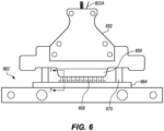
- Figure 6 is a top view of a portion of an embodiment of the catheter system 100 (illustrated in Figure 1 ) including an embodiment of a guide bundle 652 including light guides 622A and a receptacle assembly 662, the guide bundle 652 being shown in a partially connected state with respect to the receptacle assembly 662.
- the guide coupling housing 650 is advanced so that the ferrule assemblies 658 and the alignment guides 670 are partially seated within the receptacle block 664.
- Figure 7 is a simplified cross-sectional view of a portion of an embodiment of the catheter system 100 (illustrated in Figure 1 ) taken on line 7-7 in Figure 6 , the catheter system 100 including an embodiment of a guide coupling housing 750 including light guides 722A and a receptacle assembly 762, the guide coupling housing 750 being shown in a partially connected state with respect to the receptacle assembly 762.
- the guide coupling housing 750 is advanced so that the ferrule assemblies 758 and the alignment guides 770 are partially seated within the receptacle block 764.
- the ferrule assembly 758 is (i) partially extended through the receptacle hole 768, and (ii) partially engaged with the backing plate 772 of the receptacle assembly 762 so that the alignment hole 774 is aligned with the ferrule assembly 758.
- the ferrule assembly 758 can further include a spring 776, a ferrule 778, and a ferrule collar 780.
- the spring 776 can engage the ferrule 778 and/or the ferrule collar 780 within the ferrule assembly 758.
- the spring 776 can be configured to provide an insertion force when the ferrule assembly 758 is inserted into the receptacle hole 768.
- the spring 776 can vary depending on the design requirements of the catheter system 100, the light guides 222A, the guide coupling housing 750, the receptacle assembly 762, the receptacle hole 768, the ferrule 778, and/or the ferrule collar 780. It is understood that the spring 776 can include additional systems, subsystems, components, and elements than those specifically shown and/or described herein.
- the spring 776 can omit one or more of the systems, subsystems, and elements that are specifically shown and/or described herein.
- the spring 776 can be positioned in any suitable location, including those shown in Figure 7 .
- the spring 776 can be a spiral spring.
- the ferrule 778 can engage the guide proximal end 122P (illustrated in Figure 1 ) of the light guide 722A within the ferrule assembly 758.
- the ferrule 778 can fasten, reinforce, and/or seal the guide proximal end 122P of the light guide 722A.
- the ferrule 778 can vary depending on the design requirements of the catheter system 100, the light guides 722A, the guide coupling housing 750, the receptacle assembly 762, the receptacle hole 768, the spring 776, and/or the ferrule collar 780. It is understood that the ferrule 778 can include additional systems, subsystems, components, and elements than those specifically shown and/or described herein. Additionally, or alternatively, the ferrule 778 can omit one or more of the systems, subsystems, and elements that are specifically shown and/or described herein.
- the ferrule 778 can be positioned in any suitable location, including those shown in Figure 7 .
- the ferrule 778 can be formed from any suitable material. In certain embodiments, the ferrule 778 can be partially formed from a metal, a plastic, a ceramic, a polymer, a composite, and/or an organic material.
- the ferrule 778 can have a proximal end face 778P. In some embodiments, the proximal end face 778P can engage the backing plate 772 when the ferrule 778 is at least partially inserted in the receptacle hole 768. As shown in Figure 7 , the alignment hole 774 can have a smaller diameter than the ferrule 778 so that the proximal end face 778P of the ferrule 778 is seated on the alignment hole 774.
- the ferrule collar 780 can back the ferrule 778.
- the ferrule collar 780 can be seated within the spring 776.
- the ferrule 778 can vary depending on the design requirements of the catheter system 100, the light guides 222A, the guide coupling housing 750, the receptacle assembly 762, the receptacle hole 768, the spring 776, and/or the ferrule collar 780. It is understood that the ferrule 778 can include additional systems, subsystems, components, and elements than those specifically shown and/or described herein. Additionally, or alternatively, the ferrule 778 can omit one or more of the systems, subsystems, and elements that are specifically shown and/or described herein.
- the ferrule 778 can be positioned in any suitable location, including those shown in Figure 7 .
- Figure 8 is a perspective front view of a portion of an embodiment of the catheter system 100 (illustrated in Figure 1 ) including an embodiment of a receptacle assembly 862.
- Figure 8 illustrates one embodiment of the receptacle assembly 862 that is slightly different than the other embodiments described herein.
- the receptacle block 864 includes one or more receptacle holes 868 that are formed in a linear array as v-grooves, rather than singular holes.
- the v-groove receptacle holes 868 shown in Figure 8 can be formed by cutting into a hardened block of stainless steel.
- the v-grooves can be electrical discharge machine cut into the receptacle holes 868.
- the v-grooves provide at least two contact lines while the ferrule 778 is retained within the receptacle hole 868.
- the receptacle assembly 862 can include a retainer assembly 881 including a clamping bar 882 having a clamping bar axis 882a, and a plunger 884.
- the retaining assembly 881 retains the ferrule 778 within the receptacle hole 868.
- the retaining assembly 881 can be configured to reduce and/or inhibit the insertion forces required to retain the ferrule 778 within the receptacle hole 868.
- the retaining assembly 881 can vary depending on the design requirements of the catheter system 100, the receptacle assembly 862, and/or the ferrule 778. It is understood that the retaining assembly 881 can include additional systems, subsystems, components, and elements than those specifically shown and/or described herein. Additionally, or alternatively, the retaining assembly 881 can omit one or more of the systems, subsystems, and elements that are specifically shown and/or described herein. The retaining assembly 881 can be positioned in any suitable location, including those shown in Figure 8 .
- the clamping bar 882 clamps the ferrule 778 into the receptacle hole 868.
- the clamping bar 882 can be moved about the clamping bar axis 882a to apply and/or remove a retaining force onto one or more ferrule 778 (for example, see Figure 10 ).
- the clamping bar 882 can be raised and lowered thereby allowing (i) movement of the ferrule 778 upon insertion, and (ii) retention of the ferrule 778 once the proximal end face 778P is seated against the backing plate 772 (illustrated in Figure 7 ) and the clamping bar 882 is lowered to retain the ferrule 778.
- the clamping bar 882 can vary depending on the design requirements of the catheter system 100, the receptacle assembly 862, the ferrule 778, the retaining assembly 881, and/or the plunger 884. It is understood that the clamping bar 882 can include additional systems, subsystems, components, and elements than those specifically shown and/or described herein. Additionally, or alternatively, the clamping bar 882 can omit one or more of the systems, subsystems, and elements that are specifically shown and/or described herein. The clamping bar 882 can be positioned in any suitable location, including those shown in Figure 8 .
- the clamping bar 882 can include a compliant material and/or wave springs that are configured to spread a retaining force across the ferules 778 so that each of the ferrules 778 is retained within a corresponding receptacle hole 868.
- the clamping bar 882 can retain the ferrule 778 so that the ferrule 778 is not free-floating within the receptacle hole 868.
- the clamping bar 882 can also be configured to provide a uniform or substantially uniform retaining force to the ferrules 778, as known in the art.
- the plunger 884 engages (e.g., plunges) the ferrule 778 into the receptacle hole 868 so that the ferrule 778 is retained in place. In some embodiments, the plunger 884 engages the upper edges of the ferrule 778, seating it into the v-groove of the receptacle hole 868.
- the plunger 884 can vary depending on the design requirements of the catheter system 100, the receptacle assembly 862, the ferrule 778, the retaining assembly 881, and/or the clamping bar 882. It is understood that the plunger 884 can include additional systems, subsystems, components, and elements than those specifically shown and/or described herein. Additionally, or alternatively, the plunger 884 can omit one or more of the systems, subsystems, and elements that are specifically shown and/or described herein.
- the plunger 884 can be positioned in any suitable location, including those shown in Figure 8 .
- the plunger 884 can be substantially similar in form and/or function as a ball-spring plunger.
- the plunger 884 can be integrated into the clamping bar 882 (for example, as illustrated in Figure 8 ).
- Figure 9 is a front elevation view of a portion of an embodiment of the catheter system 100 (illustrated in Figure 1 ) including an embodiment of a portion of a receptacle assembly 962.
- Figure 9 illustrates one embodiment of the receptacle assembly 962 that is slightly different than the other embodiments described herein.
- greater detail is shown of the interior of the receptacle block 964 including a receptacle hole 968.
- the alignment hole 974 and the retaining assembly 981 including the clamping bar 982 and the plunger 984 are shown.
- Figure 10 is a simplified cross-sectional view of a portion of an embodiment of the catheter system 100 (illustrated in Figure 1 ) taken on line 10-10 in Figure 9 , the catheter system 100 including an embodiment of a receptacle assembly 1062.
- Figure 10 illustrates one embodiment of the receptacle assembly 1062 that is slightly different than the other embodiments described herein.
- the receptacle block 1064 includes one or more receptacle holes 1068 that are formed in a linear array as v-grooves, rather than singular holes.
- the receptacle assembly 1062 can include a retainer assembly 1081 including a clamping bar 1082, and a plunger 1084.
- the retaining assembly 1081 retains the ferrule 1078 within the receptacle hole 1068.
- the retaining assembly 1081 can be configured to reduce and/or inhibit the insertion forces required to retain the ferrule 1078 within the receptacle hole 1068.
- the clamping bar 1082 clamps the ferrule 1078 into the receptacle hole 1068.
- This technology provides a connector solution for multiple optical channels that improves optical coupling to an individual light guide organized in a multi-channel array.
- the technology can utilize individual, low-cost ferrules to terminate the light guides. These ferrules are carried in ferrule assembly included within the guide bundle.
- the guide bundle aligns the ferrules into a linear array.
- the ferrules can float within the ferrule assembly with low location tolerances.
- the connectorized ferrule assembly can mate with a high-precision receptacle assembly including a receptacle plate and/or receptacle block. Mechanical features in the receptacle assembly capture and align the individual ferrules. These features can align the floating ferrules in an improved precision array with tightly controlled tolerances.
- This technology allows a single, stable energy source to be channeled sequentially through a plurality of channels with a variable number.
- this technology provides include: 1) enabling the use of low cost, high-precision, singular ferrules on a single-use device for an increased-reliability connection thereby reducing production costs, 2) reducing the system performance dependence on the assembly of light guides into a ferrule block and the associated mechanical tolerances related to their location in a multi-channel array, 3) reducing the performance dependence on accuracy of connecting and aligning the multi-channel array to the multiplexer, 4) reducing the need for a high-cost, high-precision monolithic ferrule block.
- the light guides are optical fibers
- the energy source is a pulsed laser and the emitters are plasma generators.
- the multiplexer is a precision linear mechanism that translates coupling optics along a linear path. This approach requires a single degree of freedom.
- a connector block organizes the individual optical fibers into a liner pattern with precise interval spacing.
- the linear translation mechanism is electronically controlled by the system to line the beam path up sequentially with each individual fiber organized in the ferrule.
- the translating mechanism carries necessary beam directing optics and focusing optics to focus the laser energy onto each fiber for optimal coupling. That way, the low divergence of the laser beam over the short distance of motion of the translated coupling mechanism has a minimum impact on coupling efficiency to the fiber.
- the system drives the mechanism to align the beam path with a selected fiber optic channel and then fires the laser in pulsed or semi-continuous wave mode.
- the system can include a probe and a plurality of primary laser beams that can be combined and spot traced by beam paths that are correlated to the parametric motion of the multiplexer mechanism.
- the phrase “configured” describes a system, apparatus, or other structure that is constructed or configured to perform a particular task or adopt a particular configuration.
- the phrase “configured” can be used interchangeably with other similar phrases such as arranged and configured, constructed and arranged, constructed, manufactured and arranged, and the like.
Landscapes
- Health & Medical Sciences (AREA)
- Physics & Mathematics (AREA)
- Surgery (AREA)
- Life Sciences & Earth Sciences (AREA)
- Optics & Photonics (AREA)
- Heart & Thoracic Surgery (AREA)
- General Health & Medical Sciences (AREA)
- Nuclear Medicine, Radiotherapy & Molecular Imaging (AREA)
- Engineering & Computer Science (AREA)
- Biomedical Technology (AREA)
- Electromagnetism (AREA)
- Medical Informatics (AREA)
- Molecular Biology (AREA)
- Animal Behavior & Ethology (AREA)
- Otolaryngology (AREA)
- Public Health (AREA)
- Veterinary Medicine (AREA)
- Vascular Medicine (AREA)
- Media Introduction/Drainage Providing Device (AREA)
- Optical Couplings Of Light Guides (AREA)
- Laser Surgery Devices (AREA)
- Surgical Instruments (AREA)
Abstract
Description
- This Application claims priority on
U.S. Provisional Patent Application Serial No. 63/236,633 filed on August 24, 2021 U.S. Patent Application Serial No. 17/882,586, filed on August 7, 2022 U.S. Provisional Application Serial No. 63/236,633 U.S. Patent Application Serial No. 17/882,586 , are incorporated in their entirety herein by reference. - Vascular lesions within vessels in the body can be associated with an increased risk for major adverse events, such as myocardial infarction, embolism, deep vein thrombosis, stroke, and the like. Severe vascular lesions can be difficult to treat and achieve patency for a physician in a clinical setting.
- Vascular lesions may be treated using interventions such as drug therapy, balloon angioplasty, atherectomy, stent placement, vascular graft bypass, to name a few. Such interventions may not always be ideal or may require subsequent treatment to address the lesion.
- The present invention is directed toward a catheter system for treating a treatment site within or adjacent to a vessel wall or a heart valve. In various embodiments, the catheter system includes a light source, a first light guide, a second light guide, and a guide bundle. The light source generates light energy. The first light guide receives the light energy from the light source. The first light guide has a guide proximal end. The second light guide receives the light energy from the light source. The second light guide has a guide proximal end. A guide bundle is in optical communication with the light source. The guide bundle bundles the first light guide and the second light guide. The guide bundle includes a first ferrule that engages the guide proximal end of the first light guide, and a second ferrule that engages the guide proximal end of the second light guide.
- In some embodiments, the guide bundle further includes (i) a first ferrule assembly including the first ferrule, and (ii) a second ferrule assembly including the second ferrule.
- In certain embodiments, at least one of the first ferrule and the second ferrule are formed at least partially from a ceramic material.
- In various embodiments, at least one of the first ferrule and the second ferrule are formed at least partially from a metallic material.
- In some embodiments, the first ferrule assembly further includes a first spring that engages the first ferrule and the second ferrule assembly further includes a second spring that engages the second ferrule.
- In certain embodiments, the catheter system further includes a receptacle assembly that receives the first ferrule and the second ferrule.
- In various embodiments, the receptacle assembly is formed at least partially from a ceramic material.
- In some embodiments, the receptacle assembly is formed at least partially from a metallic material.
- In certain embodiments, the receptacle assembly includes at least one alignment guide that is configured to guide the alignment of the receptacle assembly and the guide bundle.
- In various embodiments, the alignment guide is a guide pin.
- In some embodiments, the alignment guide is a guide tongue of a tongue and groove system.
- In certain embodiments, the alignment guide is a guide rail.
- In various embodiments, the receptacle assembly includes a receptacle block that is coupled to a backing plate, the backing plate being configured to engage the first ferrule and the second ferrule.
- In some embodiments, each of the ferrules includes a proximal end face, and wherein the backing plate is configured to engage each of the proximal end faces.
- In certain embodiments, the backing plate includes (i) a first alignment hole that is configured to align a first guide beam with the first light guide, and (ii) a second alignment hole that is configured to align a second guide beam with the second light guide.
- In various embodiments, the receptacle assembly includes (i) a first receptacle hole that is configured to receive the first ferrule, and (ii) a second receptacle hole that is configured to receive the second ferrule.
- In some embodiments, the first receptacle hole and the second receptacle hole are each formed in the receptacle block, the first receptacle hole and the second receptacle hole being aligned on a same linear axis as one another.
- In certain embodiments, the first receptacle hole and the second receptacle hole are each formed in the receptacle block as v-grooves.
- In various embodiments, the receptacle assembly includes a retainer assembly that retains (i) the first ferrule in the first receptacle hole, and (ii) the second ferrule in the second receptacle hole.
- In some embodiments, the retainer assembly includes a clamping bar having a ball spring plunger, the ball spring plunger being configured to contact (i) at least a portion of the first ferrule so that the first ferrule is retained in the first receptacle hole, and (ii) at least a portion of the second ferrule so that the second ferrule is retained in the second receptacle hole.
- In certain embodiments, the clamping bar is configured to be rotatable about a clamping bar axis.
- In various embodiments, the clamping bar includes a compliant material that is configured to spread a retaining force across the ferrules so that each of the ferrules is retained within a corresponding receptacle hole.
- The present invention is also directed toward a method for treating a vascular lesion within or adjacent to a vessel wall using the catheter system of any of the embodiments described herein.
- The present invention is further directed toward a method for manufacturing the catheter system of any of the embodiments described herein.
- The present invention is also directed toward a catheter system for treating a treatment site within or adjacent to a vessel wall or a heart valve. In various embodiments, the catheter system includes a light source, a plurality of light guides, a guide bundle, and a receptacle assembly. The light source generates light energy. The plurality of light guides each individually receives the light energy from the light source. Each of the plurality of light guides has a corresponding guide proximal end. The guide bundle is in optical communication with the light source. The guide bundle bundles the plurality of light guides. The guide bundle includes a plurality of ferrules that each engages one of the guide proximal ends of a corresponding light guide. The receptacle assembly receives and aligns the plurality of ferrules into one of (i) a circular pattern, and (ii) a hexagonal pattern.
- In some embodiments, at least one of the light guides is an optical fiber.
- In certain embodiments, the light source is a laser.
- This summary is an overview of some of the teachings of the present application and is not intended to be an exclusive or exhaustive treatment of the present subject matter. Further details are found in the detailed description and appended claims. Other aspects will be apparent to persons skilled in the art upon reading and understanding the following detailed description and viewing the drawings that form a part thereof, each of which is not to be taken in a limiting sense. The scope herein is defined by the appended claims and their legal equivalents.
- The novel features of this invention, as well as the invention itself, both as to its structure and its operation, will be best understood from the accompanying drawings, taken in conjunction with the accompanying description, in which similar reference characters refer to similar parts, and in which:
-
Figure 1 is a simplified, cross-sectional view of an embodiment of a catheter system in accordance with various embodiments herein, the catheter system including a multiplexer and a guide bundle having features of the present invention; -
Figure 2 is a top view of a portion of one embodiment of the catheter system including an embodiment of a guide bundle; -
Figure 3 is a perspective front view of a portion of an embodiment of the catheter system including an embodiment of the guide bundle; -
Figure 4 is a perspective front view of a portion of an embodiment of the catheter system including one embodiment of a receptacle assembly; -
Figure 5 is a perspective rear view of a portion of an embodiment of the catheter system including one embodiment of the receptacle assembly; -
Figure 6 is a top view of a portion of an embodiment of the catheter system including an embodiment of the guide bundle and the receptacle assembly, the guide bundle being shown in a partially connected state with respect to the receptacle assembly; -
Figure 7 is a simplified cross-sectional view of a portion of an embodiment of the catheter system taken on line 7-7 inFigure 6 , the catheter system including one embodiment of a guide coupling housing and the receptacle assembly, the guide coupling housing being shown in a partially connected state with respect to the receptacle assembly; -
Figure 8 is a perspective front view of a portion of an embodiment of the catheter system including one embodiment of the receptacle assembly; -
Figure 9 is a front elevation view of a portion of an embodiment of the catheter system including one embodiment of a portion of the receptacle assembly; and -
Figure 10 is a simplified cross-sectional view of a portion of an embodiment of the catheter system taken on line 10-10 inFigure 9 , the catheter system including one embodiment of the receptacle assembly. - While embodiments of the present invention are susceptible to various modifications and alternative forms, specifics thereof have been shown by way of example and drawings, and are described in detail herein. It is understood, however, that the scope herein is not limited to the particular embodiments described. On the contrary, the intention is to cover modifications, equivalents, and alternatives falling within the spirit and scope herein.
- Treatment of vascular lesions (also sometimes referred to herein as "treatment sites") can reduce major adverse events or death in affected subjects. As referred to herein, a major adverse event is one that can occur anywhere within the body due to the presence of a vascular lesion. Major adverse events can include but are not limited to, major adverse cardiac events, major adverse events in the peripheral or central vasculature, major adverse events in the brain, major adverse events in the musculature, or major adverse events in any of the internal organs.
- As used herein, the terms "intravascular lesion", "vascular lesion" and "treatment site" are used interchangeably unless otherwise noted. The intravascular lesions and/or the vascular lesions are sometimes referred to herein simply as "lesions". Also, as used herein, the terms "focused location" and "focused spot" can be used interchangeably unless otherwise noted and can refer to any location where the light energy is focused to a small diameter than the initial diameter of the light source.
- Those of ordinary skill in the art will realize that the following detailed description of the present invention is illustrative only and is not intended to be in any way limiting. Other embodiments of the present invention will readily suggest themselves to such skilled persons having the benefit of this disclosure. Reference will now be made in detail to implementations of the present invention as illustrated in the accompanying drawings.
- In the interest of clarity, not all of the routine features of the implementations described herein are shown and described. It will, of course, be appreciated that in the development of any such actual implementation, numerous implementation-specific decisions must be made in order to achieve the developer's specific goals, such as compliance with application-related and business-related constraints, and that these specific goals will vary from one implementation to another and from one developer to another. Moreover, it is appreciated that such a development effort might be complex and time-consuming, but would nevertheless be a routine undertaking of engineering for those of ordinary skill in the art having the benefit of this disclosure.
- The catheter systems disclosed herein can include many different forms. Referring now to
Figure 1 , a schematic cross-sectional view is shown of acatheter system 100 in accordance with various embodiments. Thecatheter system 100 is suitable for imparting pressure waves to induce fractures in one or more treatment sites within or adjacent to a vessel wall of a blood vessel, or on or adjacent to a heart valve, within a body of a patient. In the embodiment illustrated inFigure 1 , thecatheter system 100 can include one or more of acatheter 102, anenergy guide bundle 122 including one ormore energy guides 122A (some embodiments described here include at least a first energy guide and a second energy guide), asource manifold 136, afluid pump 138, amultiplexer 123 including one or more of anenergy source 124, apower source 125, asystem controller 126, and a graphic user interface 127 (a "GUI"), and ahandle assembly 128. Alternatively, thecatheter system 100 can include more components or fewer components than those specifically illustrated and described in relation toFigure 1 . - It is appreciated that in some embodiments the
energy guide bundle 122 shown and described can be alight guide bundle 122, which can include one or more light guides 122A. In certain embodiments, theenergy source 124 can include alight source 124. For example, the energy guides 122A can be optical fibers, and/or theenergy source 124 can include a laser. Alternatively, theenergy guide bundle 122 can include different types ofenergy guides 122A (such as electrodes or electrode pairs), and/or a different type of energy source 124 (such as a high voltage energy source, for example). It is understood that the energy guides 122A and/or theenergy source 124 can include any suitable type of energy guides or energy sources that can generate and/or transmit energy. - In various embodiments, the
catheter 102 is configured to move to atreatment site 106 within or adjacent to avessel wall 108A of ablood vessel 108 within abody 107 of apatient 109. Thetreatment site 106 can include one or morevascular lesions 106A such as calcified vascular lesions, for example. Additionally, or in the alternative, thetreatment site 106 can includevascular lesions 106A such as fibrous vascular lesions. Still alternatively, in some implementations, thecatheter 102 can be used at atreatment site 106 within or adjacent to a heart valve within thebody 107 of thepatient 109. - The
catheter 102 can include an inflatable balloon 104 (sometimes referred to herein simply as a "balloon"), acatheter shaft 110, and aguidewire 112. Theballoon 104 can be coupled to thecatheter shaft 110. Theballoon 104 can include a balloonproximal end 104P and a balloondistal end 104D. Thecatheter shaft 110 can extend from aproximal portion 114 of thecatheter system 100 to adistal portion 116 of thecatheter system 100. Thecatheter shaft 110 can include alongitudinal axis 144. Thecatheter shaft 110 can also include aguidewire lumen 118 which is configured to move over theguidewire 112. As utilized herein, theguidewire lumen 118 defines a conduit through which theguide wire 112 extends. Thecatheter shaft 110 can further include an inflation lumen (not shown) and/or various other lumens for various other purposes. In some embodiments, thecatheter 102 can have adistal end opening 120 and can accommodate and be tracked over theguidewire 112 as thecatheter 102 is moved and positioned at or near thetreatment site 106. In some embodiments, the balloonproximal end 104P can be coupled to thecatheter shaft 110, and the balloondistal end 104D can be coupled to theguidewire lumen 118. - The
balloon 104 includes a balloon wall 130 that defines aballoon interior 146. Theballoon 104 can be selectively inflated with aballoon fluid 132 to expand from a deflated state suitable for advancing thecatheter 102 through a patient's vasculature, to an inflated state (as shown inFigure 1 ) suitable for anchoring thecatheter 102 in position relative to thetreatment site 106. Stated in another manner, when theballoon 104 is in the inflated state, the balloon wall 130 of theballoon 104 is configured to be positioned substantially adjacent to thetreatment sites 106. It is appreciated that althoughFigure 1 illustrates the balloon wall 130 of theballoon 104 is shown spaced apart from thetreatment site 106 of theblood vessel 108 when in the inflated state, this is done merely for ease of illustration. It is recognized that the balloon wall 130 of theballoon 104 will typically be substantially directly adjacent to and/or abutting thetreatment site 106 when theballoon 104 is in the inflated state. - The
balloon 104 suitable for use in thecatheter system 100 includes those that can be passed through the vasculature of apatient 109 when in the deflated state. In some embodiments, theballoon 104 is made from silicone. In other embodiments, theballoon 104 can be made from polydimethylsiloxane (PDMS), polyurethane, polymers such as PEBAX™ material, nylon, or any other suitable material. - The
balloon 104 can have any suitable diameter (in the inflated state). In various embodiments, theballoon 104 can have a diameter (in the inflated state) ranging from less than one millimeter (mm) up to 25 mm. In some embodiments, theballoon 104 can have a diameter (in the inflated state) ranging from at least 1.5 mm up to 14 mm. In some embodiments, the balloons104 can have a diameter (in the inflated state) ranging from at least two mm up to five mm. - In some embodiments, the
balloon 104 can have a length ranging from at least three mm to 300 mm. More particularly, in some embodiments, theballoon 104 can have a length ranging from at least eight mm to 200 mm. It is appreciated that aballoon 104 having a relatively longer length can be positioned adjacent tolarger treatment sites 106, and, thus, may be used for imparting pressure waves onto and inducing fractures in largervascular lesions 106A or multiplevascular lesions 106A at precise locations within thetreatment site 106. It is further appreciated that alonger balloon 104 can also be positioned adjacent tomultiple treatment sites 106 at any one given time. - The
balloon 104 can be inflated to inflation pressures of between approximately one atmosphere (atm) and 70 atm. In some embodiments, theballoon 104 can be inflated to inflation pressures of from at least 20 atm to 60 atm. In other embodiments, theballoon 104 can be inflated to inflation pressures of from at least six atm to 20 atm. In still other embodiments, theballoon 104 can be inflated to inflation pressures of from at least three atm to 20 atm. In yet other embodiments, theballoon 104 can be inflated to inflation pressures of from at least two atm to ten atm. - The
balloon 104 can have various shapes, including, but not to be limited to, a conical shape, a square shape, a rectangular shape, a spherical shape, a conical/square shape, a conical/spherical shape, an extended spherical shape, an oval shape, a tapered shape, a bone shape, a stepped diameter shape, an offset shape, or a conical offset shape. In some embodiments, theballoon 104 can include a drug eluting coating or a drug eluting stent structure. The drug eluting coating or drug eluting stent can include one or more therapeutic agents including anti-inflammatory agents, anti-neoplastic agents, anti-angiogenic agents, and the like. - The
balloon fluid 132 can be a liquid or a gas. Some examples of theballoon fluid 132 suitable for use can include, but are not limited to one or more of water, saline, contrast medium, fluorocarbons, perfluorocarbons, gases, such as carbon dioxide, or any othersuitable balloon fluid 132. In some embodiments, theballoon fluid 132 can be used as a base inflation fluid. In some embodiments, theballoon fluid 132 can include a mixture of saline to contrast medium in a volume ratio of approximately 50:50. In other embodiments, theballoon fluid 132 can include a mixture of saline to contrast medium in a volume ratio of approximately 25:75. In still other embodiments, theballoon fluid 132 can include a mixture of saline to contrast medium in a volume ratio of approximately 75:25. However, it is understood that any suitable ratio of saline to contrast medium can be used. Theballoon fluid 132 can be tailored on the basis of composition, viscosity, and the like so that the rate of travel of the pressure waves are appropriately manipulated. In certain embodiments, theballoon fluid 132 suitable for use herein is biocompatible. A volume ofballoon fluid 132 can be tailored by the chosenlight source 124 and the type ofballoon fluid 132 used. - In some embodiments, the contrast agents used in the contrast media can include, but are not to be limited to, iodine-based contrast agents, such as ionic or non-ionic iodine-based contrast agents. Some non-limiting examples of ionic iodine-based contrast agents include diatrizoate, metrizoate, iothalamate, and ioxaglate. Some non-limiting examples of non-ionic iodine-based contrast agents include iopamidol, iohexol, ioxilan, iopromide, iodixanol, and ioversol. In other embodiments, non-iodine based contrast agents can be used. Suitable non-iodine containing contrast agents can include gadolinium (III)-based contrast agents. Suitable fluorocarbon and perfluorocarbon agents can include, but are not to be limited to, agents such as perfluorocarbon dodecafluoropentane (DDFP, C5F12).
- The
balloon fluids 132 can include those that include absorptive agents that can selectively absorb light in the ultraviolet region (e.g., at least ten nanometers (nm) to 400 nm), the visible region (e.g., at least 400 nm to 780 nm), or the near-infrared region (e.g., at least 780 nm to 2.5 µm) of the electromagnetic spectrum. Suitable absorptive agents can include those with absorption maxima along the spectrum from at least ten nm to 2.5 µm. Alternatively, theballoon fluid 132 can include absorptive agents that can selectively absorb light in the mid-infrared region (e.g., at least 2.5 µm to 15 µm), or the far-infrared region (e.g., at least 15 µm to one mm) of the electromagnetic spectrum. In various embodiments, the absorptive agent can be those that have an absorption maximum matched with the emission maximum of the laser used in thecatheter system 100. By way of non-limiting examples, various lasers described herein can include neodymium:yttrium-aluminum-garnet (Nd:YAG - emission maximum = 1064 nm) lasers, holmium:YAG (Ho:YAG - emission maximum = 2.1 µm) lasers, or erbium:YAG (Er:YAG - emission maximum = 2.94 µm) lasers. In some embodiments, the absorptive agents can be water soluble. In other embodiments, the absorptive agents are not water soluble. In some embodiments, the absorptive agents used in theballoon fluids 132 can be tailored to match the peak emission of thelight source 124. Variouslight sources 124 having emission wavelengths of at least ten nanometers to one millimeter are discussed elsewhere herein. - The
catheter shaft 110 of thecatheter 102 can be coupled to the one or more light guides 122A of thelight guide bundle 122 that are in optical communication with thelight source 124. The light guide(s) 122A can be disposed along thecatheter shaft 110 and within theballoon 104. Each of the light guides 122A can have a guidedistal end 122D that is at any suitable longitudinal position relative to a length of theballoon 104. In some embodiments, eachlight guide 122A can be an optical fiber, and thelight source 124 can be a laser. Thelight source 124 can be in optical communication with the light guides 122A at theproximal portion 114 of thecatheter system 100. More particularly, thelight source 124 can selectively, simultaneously, sequentially, and/or be in optical communication with each of the light guides 122A in any desired combination, order, and/or pattern due to the presence and operation of themultiplexer 128. - In some embodiments, the
catheter shaft 110 can be coupled to multiplelight guides 122A such as a first light guide, a second light guide, a third light guide, etc., which can be disposed at any suitable positions about theguidewire lumen 118 and/or thecatheter shaft 110. For example, in certain non-exclusive embodiments, twolight guides 122A can be spaced apart by approximately 180 degrees about the circumference of theguidewire lumen 118 and/or thecatheter shaft 110; threelight guides 122A can be spaced apart by approximately 120 degrees about the circumference of theguidewire lumen 118 and/or thecatheter shaft 110, or fourlight guides 122A can be spaced apart by approximately 90 degrees about the circumference of theguidewire lumen 118 and/or thecatheter shaft 110. Still alternatively, multiplelight guides 122A need not be uniformly spaced apart from one another about the circumference of theguidewire lumen 118 and/or thecatheter shaft 110. More particularly, the light guides 122A can be disposed either uniformly or non-uniformly about theguidewire lumen 118 and/or thecatheter shaft 110 to achieve the desired effect in the desired locations. - The
catheter system 100 and/or thelight guide bundle 122 can include any number oflight guides 122A in optical communication with thelight source 124 at theproximal portion 114, and with theballoon fluid 132 within theballoon interior 146 of theballoon 104 at thedistal portion 116. For example, in some embodiments, thecatheter system 100 and/or thelight guide bundle 122 can include from onelight guide 122A to fivelight guides 122A. In other embodiments, thecatheter system 100 and/or thelight guide bundle 122 can include from fivelight guides 122A to fifteenlight guides 122A. In yet other embodiments, thecatheter system 100 and/or thelight guide bundle 122 can include from tenlight guides 122A to thirtylight guides 122A. Alternatively, in still other embodiments, thecatheter system 100 and/or thelight guide bundle 122 can include greater than 30light guides 122A. - The light guides 122A can have any suitable design for purposes of generating plasma and/or pressure waves in the
balloon fluid 132 within theballoon interior 146. In certain embodiments, the light guides 122A can include an optical fiber or flexible light pipe. The light guides 122A can be thin and flexible and can allow light signals to be sent with very little loss of strength. The light guides 122A can include a core surrounded by a cladding about its circumference. In some embodiments, the core can be a cylindrical core or a partially cylindrical core. The core and cladding of the light guides 122A can be formed from one or more materials, including but not limited to one or more types of glass, silica, or one or more polymers. The light guides 122A may also include a protective coating, such as a polymer. It is appreciated that the index of refraction of the core will be greater than the index of refraction of the cladding. - Each
light guide 122A can guide light energy along its length from a guideproximal end 122P to the guidedistal end 122D having at least one optical window (not shown) that is positioned within theballoon interior 146. - The light guides 122A can assume many configurations about and/or relative to the
catheter shaft 110 of thecatheter 102. In some embodiments, the light guides 122A can run parallel to thelongitudinal axis 144 of thecatheter shaft 110. In some embodiments, the light guides 122A can be physically coupled to thecatheter shaft 110. In other embodiments, the light guides 122A can be disposed along a length of an outer diameter of thecatheter shaft 110. In yet other embodiments, the light guides 122A can be disposed within one or more light guide lumens within thecatheter shaft 110. - The light guides 122A can also be disposed at any suitable positions about the circumference of the
guidewire lumen 118 and/or thecatheter shaft 110, and the guidedistal end 122D of each of the light guides 122A can be disposed at any suitable longitudinal position relative to the length of theballoon 104 and/or relative to the length of theguidewire lumen 118 to more effectively and precisely impart pressure waves for purposes of disrupting thevascular lesions 106A at thetreatment site 106. - In certain embodiments, the light guides 122A can include one or more
photoacoustic transducers 154, where eachphotoacoustic transducer 154 can be in optical communication with thelight guide 122A within which it is disposed. In some embodiments, thephotoacoustic transducers 154 can be in optical communication with the guidedistal end 122D of thelight guide 122A. Additionally, in such embodiments, thephotoacoustic transducers 154 can have a shape that corresponds with and/or conforms to the guidedistal end 122D of thelight guide 122A. - The
photoacoustic transducer 154 is configured to convert light energy into an acoustic wave at or near the guidedistal end 122D of thelight guide 122A. The direction of the acoustic wave can be tailored by changing an angle of the guidedistal end 122D of thelight guide 122A. - In certain embodiments, the
photoacoustic transducers 154 disposed at the guidedistal end 122D of thelight guide 122A can assume the same shape as the guidedistal end 122D of thelight guide 122A. For example, in certain non-exclusive embodiments, thephotoacoustic transducer 154 and/or the guidedistal end 122D can have a conical shape, a convex shape, a concave shape, a bulbous shape, a square shape, a stepped shape, a half-circle shape, an ovoid shape, and the like. Thelight guide 122A can further include additionalphotoacoustic transducers 154 disposed along one or more side surfaces of the length of thelight guide 122A. - In some embodiments, the light guides 122A can further include one or more diverting features or "diverters" (not shown in
Figure 1 ) within thelight guide 122A that are configured to direct light to exit thelight guide 122A toward a side surface which can be located at or near the guidedistal end 122D of thelight guide 122A, and toward the balloon wall 130. A diverting feature can include any feature of the system that diverts light energy from thelight guide 122A away from its axial path toward a side surface of thelight guide 122A. Additionally, the light guides 122A can each include one or more light windows disposed along the longitudinal or circumferential surfaces of eachlight guide 122A and in optical communication with a diverting feature. Stated in another manner, the diverting features can be configured to direct light energy in thelight guide 122A toward a side surface that is at or near the guidedistal end 122D, where the side surface is in optical communication with a light window. The light windows can include a portion of thelight guide 122A that allows light energy to exit thelight guide 122A from within thelight guide 122A, such as a portion of thelight guide 122A lacking a cladding material on or about thelight guide 122A. - Examples of the diverting features suitable for use include a reflecting element, a refracting element, and a fiber diffuser. The diverting features suitable for focusing light energy away from the tip of the light guides 122A can include but are not to be limited to, those having a convex surface, a gradient-index (GRIN) lens, and a mirror focus lens. Upon contact with the diverting feature, the light energy is diverted within the
light guide 122A to one or more of aplasma generator 133 and thephotoacoustic transducer 154 that is in optical communication with a side surface of thelight guide 122A. As noted, thephotoacoustic transducer 154 then converts light energy into an acoustic wave that extends away from the side surface of thelight guide 122A. - The source manifold 136 can be positioned at or near the
proximal portion 114 of thecatheter system 100. The source manifold 136 can include one or more proximal end openings that can receive the one or more light guides 122A of thelight guide bundle 122, theguidewire 112, and/or aninflation conduit 140 that is coupled in fluid communication with thefluid pump 138. Thecatheter system 100 can also include thefluid pump 138 that is configured to inflate theballoon 104 with theballoon fluid 132 as needed. - As noted above, in the embodiment illustrated in
Figure 1 , themultiplexer 123 includes one or more of thelight source 124, thepower source 125, thesystem controller 126, and theGUI 127. Alternatively, themultiplexer 123 can include more components or fewer components than those specifically illustrated inFigure 1 . For example, in certain non-exclusive alternative embodiments, themultiplexer 123 can be designed without theGUI 127. Still alternatively, one or more of thelight source 124, thepower source 125, thesystem controller 126, and theGUI 127 can be provided within thecatheter system 100 without the specific need for themultiplexer 123. - In some embodiments, the
multiplexer 123 can include a two-channel splitter design. Thelight guide bundle 122 can include a manual positioning mechanism that is mounted on an optical breadboard and/or platen. This design enables linear positional adjustment and array tilting by rotating about a channel onelight guide 122A axis (not shown inFigure 1 ). The adjustment method, in other embodiments, can include at least two adjustment steps, 1) aligning the planar positions of thesource beam 124B atChannel 1, and 2) adjusting thelight guide bundle 122 to achieve the best alignment atChannel 10. - As shown, the
multiplexer 123, and the components included therewith, is operatively coupled to thecatheter 102, thelight guide bundle 122, and the remainder of thecatheter system 100. For example, in some embodiments, as illustrated inFigure 1 , themultiplexer 123 can include a console connection aperture 148 (also sometimes referred to generally as a "socket") by which thelight guide bundle 122 is mechanically coupled to themultiplexer 123. In such embodiments, thelight guide bundle 122 can include aguide coupling housing 150 that houses a portion, e.g., the guideproximal end 122P, of each of the light guides 122A. Theguide coupling housing 150 is configured to fit and be selectively retained within theconsole connection aperture 148 to provide the mechanical coupling between thelight guide bundle 122 and themultiplexer 123. - The
light guide bundle 122 can also include a guide bundle 152 (or "shell") that brings each of the individual light guides 122A closer together so that the light guides 122A and/or thelight guide bundle 122 can be in a more compact form as it extends with thecatheter 102 into theblood vessel 108 during use of thecatheter system 100. In some embodiments, the light guides 122A leading to theplasma generator 133 can be organized into alight guide bundle 122 including a linear block with an array of precision holes forming a multi-channel ferrule 778 (illustrated inFigure 7 , for example). In other embodiments, thelight guide bundle 122 could include a mechanical connector array or block connector that organizessingular ferrules 778 into one of (i) a linear array, (ii) a circular pattern, and (iii) a hexagonal pattern. - The
light source 124 can be selectively and/or alternatively coupled in optical communication with each of the light guides 122A, i.e. to the guideproximal end 122P of each of the light guides 122A, in thelight guide bundle 122. In particular, thelight source 124 is configured to generate light energy in the form of asource beam 124A, such as a pulsed source beam, that can be selectively and/or alternatively directed to and received by each of the light guides 122A in thelight guide bundle 122 as anindividual guide beam 124B. Alternatively, thecatheter system 100 can include more than onelight source 124. For example, in one non-exclusive alternative embodiment, thecatheter system 100 can include a separatelight source 124 for each of the light guides 122A in thelight guide bundle 122. Thelight source 124 can be operated at low energies. - The
light source 124 can have any suitable design. In certain embodiments, thelight source 124 can be configured to provide sub-millisecond pulses of light energy from thelight source 124 that are focused onto a small spot in order to couple it into the guideproximal end 122P of thelight guide 122A. Such pulses of light energy are then directed and/or guided along the light guides 122A to a location within theballoon interior 146 of theballoon 104, thereby inducing plasma formation (also sometimes referred to herein as a "plasma flash") in theballoon fluid 132 within theballoon interior 146 of theballoon 104, such as via theplasma generator 133 that can be located at the guidedistal end 122D of thelight guide 122A. In particular, the light emitted at the guidedistal end 122D of thelight guide 122A energizes theplasma generator 133 to form the plasma within theballoon fluid 132 within theballoon interior 146. The plasma formation causes rapid bubble formation and imparts pressure waves upon thetreatment site 106. An exemplary plasma-inducedbubble 134 is illustrated inFigure 1 . - In various non-exclusive alternative embodiments, the sub-millisecond pulses of light energy from the
light source 124 can be delivered to thetreatment site 106 at a frequency of between approximately one hertz (Hz) and 5000 Hz, between approximately 30 Hz and 1000 Hz, between approximately ten Hz and 100 Hz, or between approximately one Hz and 30 Hz. Alternatively, the sub-millisecond pulses of light energy can be delivered to thetreatment site 106 at a frequency that can be greater than 5000 Hz or less than one Hz, or any other suitable range of frequencies. - It is appreciated that although the
light source 124 is typically utilized to provide pulses of light energy, thelight source 124 can still be described as providing asingle source beam 124A, i.e. a single pulsed source beam. - The
light sources 124 suitable for use can include various types of light sources including lasers and lamps. For example, in certain non-exclusive embodiments, thelight source 124 can be an infrared laser that emits light energy in the form of pulses of infrared light. Alternatively, as noted above, thelight sources 124, as referred to herein, can include any suitable type of energy source. - Suitable lasers can include short pulse lasers on the sub-millisecond timescale. In some embodiments, the
light source 124 can include lasers on the nanosecond (ns) timescale. The lasers can also include short pulse lasers on the picosecond (ps), femtosecond (fs), and microsecond (us) timescales. It is appreciated that there are many combinations of laser wavelengths, pulse widths, and energy levels that can be employed to achieve plasma in theballoon fluid 132 of thecatheter 102. In various non-exclusive alternative embodiments, the pulse widths can include those falling within a range including from at least ten ns to 3000 ns, at least 20 ns to 100 ns, or at least one ns to 500 ns. Alternatively, any other suitable pulse width range can be used. - Exemplary nanosecond lasers can include those within the UV to IR spectrum, spanning wavelengths of about ten nanometers (nm) to one millimeter (mm). In some embodiments, the
light sources 124 suitable for use in thecatheter system 100 can include those capable of producing light at wavelengths of from at least 750 nm to 2000 nm. In other embodiments, thelight sources 124 can include those capable of producing light at wavelengths of from at least 700 nm to 3000 nm. In still other embodiments, thelight sources 124 can include those capable of producing light at wavelengths of from at least 100 nm to ten micrometers (µm). Nanosecond lasers can include those having repetition rates of up to 200 kHz. In some embodiments, the laser can include a Q-switched thulium:yttrium-aluminum-garnet (Tm:YAG) laser. In other embodiments, the laser can include a neodymium:yttrium-aluminum-garnet (Nd:YAG) laser, holmium:yttrium-aluminum-garnet (Ho:YAG) laser, erbium:yttrium-aluminum-garnet (Er:YAG) laser, excimer laser, helium-neon laser, carbon dioxide laser, as well as doped, pulsed, fiber lasers. - The
catheter system 100 can generate pressure waves having maximum pressures in the range of at least one megapascal (MPa) to 100 MPa. The maximum pressure generated by aparticular catheter system 100 will depend on thelight source 124, the absorbing material, the bubble expansion, the propagation medium, the balloon material, and other factors. In various non-exclusive alternative embodiments, thecatheter system 100 can generate pressure waves having maximum pressures in the range of at least approximately two MPa to 50 MPa, at least approximately two MPa to 30 MPa, or at least approximately 15 MPa to 25 MPa. - The pressure waves can be imparted upon the
treatment site 106 from a distance within a range from at least approximately 0.1 millimeters (mm) to greater than approximately 25 mm extending radially from the light guides 122A when thecatheter 102 is placed at thetreatment site 106. In various non-exclusive alternative embodiments, the pressure waves can be imparted upon thetreatment site 106 from a distance within a range from at least approximately ten mm to 20 mm, at least approximately one mm to ten mm, at least approximately 1.5 mm to four mm, or at least approximately 0.1 mm to ten mm extending radially from the light guides 122A when thecatheter 102 is placed at thetreatment site 106. In other embodiments, the pressure waves can be imparted upon thetreatment site 106 from another suitable distance that is different than the foregoing ranges. In some embodiments, the pressure waves can be imparted upon thetreatment site 106 within a range of at least approximately two MPa to 30 MPa at a distance from at least approximately 0.1 mm to ten mm. In some embodiments, the pressure waves can be imparted upon thetreatment site 106 from a range of at least approximately two MPa to 25 MPa at a distance from at least approximately 0.1 mm to ten mm. Still alternatively, other suitable pressure ranges and distances can be used. - The
power source 125 is electrically coupled to and is configured to provide the necessary power to each of thelight source 124, thesystem controller 126, theGUI 127, and thehandle assembly 128. Thepower source 125 can have any suitable design for such purposes. - The
system controller 126 is electrically coupled to and receives power from thepower source 125. Additionally, thesystem controller 126 is coupled to and is configured to control the operation of each of thelight source 124, and theGUI 127. Thesystem controller 126 can include one or more processors or circuits for purposes of controlling the operation of at least thelight source 124, and theGUI 127. For example, thesystem controller 126 can control thelight source 124 for generating pulses of light energy as desired and/or at any desired firing rate. - The
system controller 126 can further be configured to control the operation of other components of thecatheter system 100 such as the positioning of thecatheter 102 adjacent to thetreatment site 106, the inflation of theballoon 104 with theballoon fluid 132, etc. Further, or in the alternative, thecatheter system 100 can include one or more additional controllers that can be positioned in any suitable manner for purposes of controlling the various operations of thecatheter system 100. For example, in certain embodiments, an additional controller and/or a portion of thesystem controller 126 can be positioned and/or incorporated within thehandle assembly 128. - The
GUI 127 is accessible by the user or operator of thecatheter system 100. Additionally, theGUI 127 is electrically connected to thesystem controller 126. With such design, theGUI 127 can be used by the user or operator to ensure that thecatheter system 100 is effectively utilized to impart pressure onto and induce fractures at the treatment site(s) 106. TheGUI 127 can provide the user or operator with information that can be used before, during, and after use of thecatheter system 100. In one embodiment, theGUI 127 can provide static visual data and/or information to the user or operator. In addition, or in the alternative, theGUI 127 can provide dynamic visual data and/or information to the user or operator, such as video data or any other data that changes over time during the use of thecatheter system 100. In various embodiments, theGUI 127 can include one or more colors, different sizes, varying brightness, etc., that may act as alerts to the user or operator. Additionally, or in the alternative, theGUI 127 can provide audio data or information to the user or operator. The specifics of theGUI 127 can vary depending upon the design requirements of thecatheter system 100, or the specific needs, specifications, and/or desires of the user or operator. - As shown in
Figure 1 , thehandle assembly 128 can be positioned at or near theproximal portion 114 of thecatheter system 100, and/or near thesource manifold 136. In this embodiment, thehandle assembly 128 is coupled to theballoon 104 and is positioned spaced apart from theballoon 104. Alternatively, thehandle assembly 128 can be positioned at another suitable location. - The
handle assembly 128 is handled and used by the user or operator to operate, position, and control thecatheter 102. The design and specific features of thehandle assembly 128 can vary to suit the design requirements of thecatheter system 100. In the embodiment illustrated inFigure 1 , thehandle assembly 128 is separate from, but in electrical and/or fluid communication with one or more of thesystem controller 126, thelight source 124, thefluid pump 138, and theGUI 127. In some embodiments, thehandle assembly 128 can integrate and/or include at least a portion of thesystem controller 126 within an interior of thehandle assembly 128. For example, as shown, in certain such embodiments, thehandle assembly 128 can includecircuitry 156 that can form at least a portion of thesystem controller 126. - In one embodiment, the
circuitry 156 can include a printed circuit board having one or more integrated circuits, or any other suitable circuitry. In an alternative embodiment, thecircuitry 156 can be omitted or can be included within thesystem controller 126, which in various embodiments can be positioned outside of thehandle assembly 128, e.g., within themultiplexer 123. It is understood that thehandle assembly 128 can include fewer or additional components than those specifically illustrated and described herein. -
Figure 2 is a top view of a portion of an embodiment of the catheter system 100 (illustrated inFigure 1 ) including an embodiment of aguide bundle 252. As illustrated in the embodiment inFigure 2 , theguide coupling housing 250 houses one ormore ferrule assemblies 258 and one or morealignment guide receivers 260. Theferrule assemblies 258 can each include a ferrule 778 (illustrated inFigure 7 , for example), a portion of the individuallight guide 222A, including the guideproximal end 122P (illustrated inFigure 1 , for example), and a spring 776 (illustrated inFigure 7 , for example). Theferrule assembly 258 can retain theferrule 778. In certain embodiments, thelight guide 222A can be engaged by aferrule assembly 258. In particular, the guideproximal end 122P can be terminated intoindividual ferrules 778 of theferrule assembly 258. Theferrule assembly 258 can be configured to provide increased localization and improved alignment guides that enable eachferrule 778 to be inserted into receptacle holes 468 (illustrated inFigure 4 , for example) within the receptacle assembly 462 (illustrated inFigure 4 , for example) without damaging theferrules 778. - The
ferrule assembly 258 can vary depending on the design requirements of thecatheter system 100, thelight guide 222A, the guideproximal end 122P, and/or guidebundle 252. It is understood that theferrule assembly 258 can include additional systems, subsystems, components, and elements than those specifically shown and/or described herein. Additionally, or alternatively, theferrule assembly 258 can omit one or more of the systems, subsystems, and elements that are specifically shown and/or described herein. Theferrule assembly 258 can be positioned in any suitable location, including those shown inFigure 2 . - The
ferrule assembly 258 can vary in shape. In some embodiments, theferrule assembly 258 can be substantially plug-shaped, as shown in the embodiment illustrated inFigure 2 . In other embodiments, theferrule assembly 258 can be substantially cylindrical-shaped, prism-shaped, cube-shaped, cuboid-shaped, and/or tube-shaped. - The
ferrule assembly 258 can be formed with any suitable material. In certain embodiments, theferrule assembly 258 can be at least partially formed from a metal, a plastic, a polymer, a ceramic, a composite, and/or an organic material. In other embodiments, theferrule assembly 258 can be formed using mold-injected plastics. - The
alignment guide receiver 260 receives an alignment guide 470 (illustrated inFigure 4 , for example). Thealignment guide receiver 260 can be configured to improve the mating of theferrule 778 with thereceptacle hole 468 within thereceptacle assembly 462. - The
alignment guide receiver 260 can vary depending on the design requirements of thecatheter system 100, theguide bundle 252, and/or thealignment guide 470. It is understood that thealignment guide receiver 260 can include additional systems, subsystems, components, and elements than those specifically shown and/or described herein. Additionally, or alternatively, thealignment guide receiver 260 can omit one or more of the systems, subsystems, and elements that are specifically shown and/or described herein. Thealignment guide receiver 260 can be positioned in any suitable location, including those shown inFigure 2 . - In the embodiment shown in
Figure 2 , thealignment guide receiver 260 is a pin receiver. Non-limiting, non-exclusive examples of suitable alignment guide receivers include (i) a guide groove of a tongue and groove system, (ii) a guide slot of a tab and slot system, and (iii) a guide channel of a rail and channel system. -
Figure 3 is a perspective front view of a portion of an embodiment of the catheter system 100 (illustrated inFigure 1 ) including an embodiment of aguide bundle 352. In particular, greater detail of the shape and design of the embodiments of theguide coupling housing 350, theguide bundle 352, and theferrule assembly 358 are illustrated inFigure 3 . For example, as shown inFigure 3 , theguide coupling housing 350 can have a substantially trapezoidal side-profile and a substantially trapezoidal-prism shape. Theguide coupling housing 350 can extend outwardly from theguide bundle 352. Theguide coupling housing 350 can include one or more apertures, each of theferrule assemblies 358 can extend through corresponding apertures. As illustrated in the embodiment inFigure 3 , theferrule assemblies 358 can be substantially cylindrical with a partially spherical end portion. Theferrule assemblies 358 can include an opening or orifice in order to receive the guide beams 122B (illustrated inFigure 1 ) from the multiplexer 128 (Illustrated inFigure 1 ). -
Figure 4 is a perspective front view of a portion of an embodiment of the catheter system 100 (illustrated inFigure 1 ) including an embodiment of areceptacle assembly 462. As illustrated in the embodiment inFigure 4 , thereceptacle assembly 462 can include one or more of areceptacle block 464, areceptacle housing 466, areceptacle hole 468, and analignment guide 470. Thereceptacle assembly 462 can be configured to mate with the guide bundle 252 (illustrated inFigure 2 , for example) so that the guide beams 122B are aligned with each of the light guides 222A (illustrated inFigure 2 , for example) within theguide bundle 252. - The
receptacle assembly 462 can vary depending on the design requirements of thecatheter system 100, the light guides 222A, theguide bundle 252 and/or the ferrule assembly 358 (illustrated inFigure 3 , for example). It is understood that thereceptacle assembly 462 can include additional systems, subsystems, components, and elements than those specifically shown and/or described herein. Additionally, or alternatively, thereceptacle assembly 462 can omit one or more of the systems, subsystems, and elements that are specifically shown and/or described herein. Thereceptacle assembly 462 can be positioned in any suitable location, including those shown inFigure 4 . - The
receptacle assembly 462 can be formed from any suitable material. In some embodiments, the components of thereceptacle assembly 462 can be formed at least partially from a metal, a plastic, a ceramic, a polymer, a composite, and/or an organic material. In certain embodiments, the components of thereceptacle assembly 462 can be formed from a hardened stainless steel configured to have increased resilience and resistance to wear and tear. - The
receptacle block 464 can be configured to receive theguide bundle 252. Thereceptacle block 464 can vary depending on the design requirements of thecatheter system 100, the light guides 222A, theguide bundle 252, and/or thereceptacle assembly 462. It is understood that thereceptacle block 464 can include additional systems, subsystems, components, and elements than those specifically shown and/or described herein. Additionally, or alternatively, thereceptacle block 464 can omit one or more of the systems, subsystems, and elements that are specifically shown and/or described herein. Thereceptacle block 464 can be positioned in any suitable location, including those shown inFigure 4 . - The
receptacle housing 466 can house thereceptacle block 464. In some embodiments, thereceptacle housing 466 can be coupled to thereceptacle block 464. Thereceptacle housing 466 can vary depending on the design requirements of thecatheter system 100, the light guides 222A, theguide bundle 252, thereceptacle assembly 462, and/or thereceptacle block 464. It is understood that thereceptacle housing 466 can include additional systems, subsystems, components, and elements than those specifically shown and/or described herein. Additionally, or alternatively, thereceptacle housing 466 can omit one or more of the systems, subsystems, and elements that are specifically shown and/or described herein. Thereceptacle housing 466 can be positioned in any suitable location, including those shown inFigure 4 . - The
receptacle hole 468 can be precision-bored into thereceptacle block 464. Alternatively, thereceptacle hole 468 can be formed in thereceptacle block 464 by any suitable method known in the art. As shown in the embodiment inFigure 4 , one or more receptacle holes 468 can be aligned in a linear array in thereceptacle block 464. Thereceptacle hole 468 can vary depending on the design requirements of thecatheter system 100, the light guides 222A, theguide bundle 252, thereceptacle assembly 462, and/or thereceptacle block 464. It is understood that thereceptacle hole 468 can include additional systems, subsystems, components, and elements than those specifically shown and/or described herein. Additionally, or alternatively, thereceptacle hole 468 can omit one or more of the systems, subsystems, and elements that are specifically shown and/or described herein. - The
receptacle hole 468 can be positioned in any suitable location, including those shown inFigure 4 . Thereceptacle assembly 462 can include any suitable number of receptacle holes 468 such as 1, 2, 3, 4, 5, 7, 8, 9, or 10 receptacle holes 468. In other embodiments, thereceptacle assembly 462 can include greater than 10 receptacle holes 468. - The
alignment guide 470 can be coupled to thereceptacle block 464. Thealignment guide 470 can mate with the alignment guide receiver 260 (illustrated inFigure 2 ) so that theguide bundle 252 and thereceptacle assembly 464 are at least partially aligned and/or coupled (for example, as illustrated inFigure 6 ). Thealignment guide 470 can vary depending on the design requirements of thecatheter system 100, the light guides 222A, theguide bundle 252, thealignment guide receiver 260, thereceptacle assembly 462, and/or thereceptacle block 464. It is understood that thealignment guide 470 can include additional systems, subsystems, components, and elements than those specifically shown and/or described herein. Additionally, or alternatively, thealignment guide 470 can omit one or more of the systems, subsystems, and elements that are specifically shown and/or described herein. - The
alignment guide 470 can be positioned in any suitable location, including those shown inFigure 4 . Thealignment guide 470 can be substantially dowel-shaped. Thereceptacle assembly 462 can include any suitable number of alignment guides 470 such as 1, 2, 3, 4, 5, 7, 8, 9, or 10 alignment guides 470. In other embodiments, thereceptacle assembly 462 can include greater than 10 alignment guides 470. Thealignment guide 470 can be anysuitable alignment guide 470 known within the art. In the embodiment shown inFigure 4 , thealignment guide 470 is a guide pin. Non-limiting, non-exclusive examples of suitable alignment guides include (i) a guide tongue of a tongue and groove system, (ii) a guide tab of a tab and slot system, and (iii) a guide rail of a rail and channel system. -
Figure 5 is a perspective rear view of a portion of an embodiment of the catheter system 100 (illustrated inFigure 1 ) including an embodiment of areceptacle assembly 562. As illustrated in the embodiment displayed inFigure 5 , thereceptacle assembly 562 can include areceptacle housing 566 and abacking plate 572 including one or more alignment holes 574. - The
backing plate 572 can be configured to receive a proximal end face of the ferrules 766. Thebacking plate 572 can provide a precision reference plane for aligning the guide beams 122B from themultiplexer 128 to each of the corresponding light guides 122A (illustrated inFigure 1 ). The alignment holes 574 can be precision-bored into thebacking plate 572. The alignment holes 574 can be formed into thebacking plate 572 using any suitable method known in the art. The alignment holes 574 can be configured to couple the focused guide beams 122B with each of the corresponding light guides 122A. - The
backing plate 572 andalignment holes 574 can vary depending on the design requirements of thecatheter system 100, the light guides 222A, theguide bundle 252, thealignment guide receiver 260, thereceptacle assembly 462, and/or thereceptacle block 464. It is understood that thebacking plate 572 can include additional systems, subsystems, components, and elements than those specifically shown and/or described herein. Additionally, or alternatively, thebacking plate 572 can omit one or more of the systems, subsystems, and elements that are specifically shown and/or described herein. Thebacking plate 572 andalignment holes 574 can be positioned in any suitable location, including those shown inFigure 5 . In certain embodiments, the alignment holes 574 can have a smaller diameter than the diameter of theferrule 778. The alignment holes 574 can have a sufficiently-sized diameter in order to accommodate the entire guide beam 128B without clipping. -
Figure 6 is a top view of a portion of an embodiment of the catheter system 100 (illustrated inFigure 1 ) including an embodiment of aguide bundle 652 including light guides 622A and areceptacle assembly 662, theguide bundle 652 being shown in a partially connected state with respect to thereceptacle assembly 662. In particular, in the embodiment illustrated inFigure 6 , theguide coupling housing 650 is advanced so that theferrule assemblies 658 and the alignment guides 670 are partially seated within thereceptacle block 664. -
Figure 7 is a simplified cross-sectional view of a portion of an embodiment of the catheter system 100 (illustrated inFigure 1 ) taken on line 7-7 inFigure 6 , thecatheter system 100 including an embodiment of aguide coupling housing 750 including light guides 722A and areceptacle assembly 762, theguide coupling housing 750 being shown in a partially connected state with respect to thereceptacle assembly 762. In particular, in the embodiment illustrated inFigure 7 , theguide coupling housing 750 is advanced so that theferrule assemblies 758 and the alignment guides 770 are partially seated within thereceptacle block 764. InFigure 7 , theferrule assembly 758 is (i) partially extended through thereceptacle hole 768, and (ii) partially engaged with thebacking plate 772 of thereceptacle assembly 762 so that thealignment hole 774 is aligned with theferrule assembly 758. As illustrated in the embodiment displayed inFigure 7 , theferrule assembly 758 can further include aspring 776, aferrule 778, and aferrule collar 780. - The
spring 776 can engage theferrule 778 and/or theferrule collar 780 within theferrule assembly 758. Thespring 776 can be configured to provide an insertion force when theferrule assembly 758 is inserted into thereceptacle hole 768. Thespring 776 can vary depending on the design requirements of thecatheter system 100, the light guides 222A, theguide coupling housing 750, thereceptacle assembly 762, thereceptacle hole 768, theferrule 778, and/or theferrule collar 780. It is understood that thespring 776 can include additional systems, subsystems, components, and elements than those specifically shown and/or described herein. Additionally, or alternatively, thespring 776 can omit one or more of the systems, subsystems, and elements that are specifically shown and/or described herein. Thespring 776 can be positioned in any suitable location, including those shown inFigure 7 . Thespring 776 can be a spiral spring. - The
ferrule 778 can engage the guideproximal end 122P (illustrated inFigure 1 ) of thelight guide 722A within theferrule assembly 758. Theferrule 778 can fasten, reinforce, and/or seal the guideproximal end 122P of thelight guide 722A. Theferrule 778 can vary depending on the design requirements of thecatheter system 100, the light guides 722A, theguide coupling housing 750, thereceptacle assembly 762, thereceptacle hole 768, thespring 776, and/or theferrule collar 780. It is understood that theferrule 778 can include additional systems, subsystems, components, and elements than those specifically shown and/or described herein. Additionally, or alternatively, theferrule 778 can omit one or more of the systems, subsystems, and elements that are specifically shown and/or described herein. Theferrule 778 can be positioned in any suitable location, including those shown inFigure 7 . - The
ferrule 778 can be formed from any suitable material. In certain embodiments, theferrule 778 can be partially formed from a metal, a plastic, a ceramic, a polymer, a composite, and/or an organic material. Theferrule 778 can have aproximal end face 778P. In some embodiments, theproximal end face 778P can engage thebacking plate 772 when theferrule 778 is at least partially inserted in thereceptacle hole 768. As shown inFigure 7 , thealignment hole 774 can have a smaller diameter than theferrule 778 so that theproximal end face 778P of theferrule 778 is seated on thealignment hole 774. - The
ferrule collar 780 can back theferrule 778. Theferrule collar 780 can be seated within thespring 776. Theferrule 778 can vary depending on the design requirements of thecatheter system 100, the light guides 222A, theguide coupling housing 750, thereceptacle assembly 762, thereceptacle hole 768, thespring 776, and/or theferrule collar 780. It is understood that theferrule 778 can include additional systems, subsystems, components, and elements than those specifically shown and/or described herein. Additionally, or alternatively, theferrule 778 can omit one or more of the systems, subsystems, and elements that are specifically shown and/or described herein. Theferrule 778 can be positioned in any suitable location, including those shown inFigure 7 . -
Figure 8 is a perspective front view of a portion of an embodiment of the catheter system 100 (illustrated inFigure 1 ) including an embodiment of areceptacle assembly 862.Figure 8 illustrates one embodiment of thereceptacle assembly 862 that is slightly different than the other embodiments described herein. In the embodiment illustrated inFigure 8 , thereceptacle block 864 includes one or more receptacle holes 868 that are formed in a linear array as v-grooves, rather than singular holes. - In some embodiments, the v-groove receptacle holes 868 shown in
Figure 8 can be formed by cutting into a hardened block of stainless steel. The v-grooves can be electrical discharge machine cut into the receptacle holes 868. The v-grooves provide at least two contact lines while theferrule 778 is retained within thereceptacle hole 868. In the embodiment illustrated inFigure 8 , thereceptacle assembly 862 can include aretainer assembly 881 including a clampingbar 882 having a clampingbar axis 882a, and aplunger 884. The retainingassembly 881 retains theferrule 778 within thereceptacle hole 868. The retainingassembly 881 can be configured to reduce and/or inhibit the insertion forces required to retain theferrule 778 within thereceptacle hole 868. - The retaining
assembly 881 can vary depending on the design requirements of thecatheter system 100, thereceptacle assembly 862, and/or theferrule 778. It is understood that the retainingassembly 881 can include additional systems, subsystems, components, and elements than those specifically shown and/or described herein. Additionally, or alternatively, the retainingassembly 881 can omit one or more of the systems, subsystems, and elements that are specifically shown and/or described herein. The retainingassembly 881 can be positioned in any suitable location, including those shown inFigure 8 . - The clamping
bar 882 clamps theferrule 778 into thereceptacle hole 868. The clampingbar 882 can be moved about the clampingbar axis 882a to apply and/or remove a retaining force onto one or more ferrule 778 (for example, seeFigure 10 ). In certain embodiments, the clampingbar 882 can be raised and lowered thereby allowing (i) movement of theferrule 778 upon insertion, and (ii) retention of theferrule 778 once theproximal end face 778P is seated against the backing plate 772 (illustrated inFigure 7 ) and the clampingbar 882 is lowered to retain theferrule 778. - The clamping
bar 882 can vary depending on the design requirements of thecatheter system 100, thereceptacle assembly 862, theferrule 778, the retainingassembly 881, and/or theplunger 884. It is understood that the clampingbar 882 can include additional systems, subsystems, components, and elements than those specifically shown and/or described herein. Additionally, or alternatively, the clampingbar 882 can omit one or more of the systems, subsystems, and elements that are specifically shown and/or described herein. The clampingbar 882 can be positioned in any suitable location, including those shown inFigure 8 . - The clamping
bar 882 can include a compliant material and/or wave springs that are configured to spread a retaining force across theferules 778 so that each of theferrules 778 is retained within a correspondingreceptacle hole 868. The clampingbar 882 can retain theferrule 778 so that theferrule 778 is not free-floating within thereceptacle hole 868. The clampingbar 882 can also be configured to provide a uniform or substantially uniform retaining force to theferrules 778, as known in the art. - The
plunger 884 engages (e.g., plunges) theferrule 778 into thereceptacle hole 868 so that theferrule 778 is retained in place. In some embodiments, theplunger 884 engages the upper edges of theferrule 778, seating it into the v-groove of thereceptacle hole 868. Theplunger 884 can vary depending on the design requirements of thecatheter system 100, thereceptacle assembly 862, theferrule 778, the retainingassembly 881, and/or the clampingbar 882. It is understood that theplunger 884 can include additional systems, subsystems, components, and elements than those specifically shown and/or described herein. Additionally, or alternatively, theplunger 884 can omit one or more of the systems, subsystems, and elements that are specifically shown and/or described herein. - The
plunger 884 can be positioned in any suitable location, including those shown inFigure 8 . Theplunger 884 can be substantially similar in form and/or function as a ball-spring plunger. Theplunger 884 can be integrated into the clamping bar 882 (for example, as illustrated inFigure 8 ). -
Figure 9 is a front elevation view of a portion of an embodiment of the catheter system 100 (illustrated inFigure 1 ) including an embodiment of a portion of areceptacle assembly 962.Figure 9 illustrates one embodiment of thereceptacle assembly 962 that is slightly different than the other embodiments described herein. In the embodiment illustrated inFigure 9 , greater detail is shown of the interior of thereceptacle block 964 including areceptacle hole 968. InFigure 9 , thealignment hole 974 and the retainingassembly 981 including the clampingbar 982 and theplunger 984 are shown. -
Figure 10 is a simplified cross-sectional view of a portion of an embodiment of the catheter system 100 (illustrated inFigure 1 ) taken on line 10-10 inFigure 9 , thecatheter system 100 including an embodiment of areceptacle assembly 1062.Figure 10 illustrates one embodiment of thereceptacle assembly 1062 that is slightly different than the other embodiments described herein. In the embodiment illustrated inFigure 10 , thereceptacle block 1064 includes one ormore receptacle holes 1068 that are formed in a linear array as v-grooves, rather than singular holes. In the embodiment illustrated inFigure 10 , thereceptacle assembly 1062 can include aretainer assembly 1081 including aclamping bar 1082, and aplunger 1084. The retainingassembly 1081 retains theferrule 1078 within thereceptacle hole 1068. The retainingassembly 1081 can be configured to reduce and/or inhibit the insertion forces required to retain theferrule 1078 within thereceptacle hole 1068. The clampingbar 1082 clamps theferrule 1078 into thereceptacle hole 1068. - This technology provides a connector solution for multiple optical channels that improves optical coupling to an individual light guide organized in a multi-channel array. The technology can utilize individual, low-cost ferrules to terminate the light guides. These ferrules are carried in ferrule assembly included within the guide bundle. In some embodiments, the guide bundle aligns the ferrules into a linear array. The ferrules can float within the ferrule assembly with low location tolerances. The connectorized ferrule assembly can mate with a high-precision receptacle assembly including a receptacle plate and/or receptacle block. Mechanical features in the receptacle assembly capture and align the individual ferrules. These features can align the floating ferrules in an improved precision array with tightly controlled tolerances. This technology allows a single, stable energy source to be channeled sequentially through a plurality of channels with a variable number.
- Specific advantages this technology provides include: 1) enabling the use of low cost, high-precision, singular ferrules on a single-use device for an increased-reliability connection thereby reducing production costs, 2) reducing the system performance dependence on the assembly of light guides into a ferrule block and the associated mechanical tolerances related to their location in a multi-channel array, 3) reducing the performance dependence on accuracy of connecting and aligning the multi-channel array to the multiplexer, 4) reducing the need for a high-cost, high-precision monolithic ferrule block.
- In some embodiments the light guides are optical fibers, the energy source is a pulsed laser and the emitters are plasma generators. In its simplest form, the multiplexer is a precision linear mechanism that translates coupling optics along a linear path. This approach requires a single degree of freedom. A connector block organizes the individual optical fibers into a liner pattern with precise interval spacing.
- In certain embodiments, the linear translation mechanism is electronically controlled by the system to line the beam path up sequentially with each individual fiber organized in the ferrule. The translating mechanism carries necessary beam directing optics and focusing optics to focus the laser energy onto each fiber for optimal coupling. That way, the low divergence of the laser beam over the short distance of motion of the translated coupling mechanism has a minimum impact on coupling efficiency to the fiber. The system drives the mechanism to align the beam path with a selected fiber optic channel and then fires the laser in pulsed or semi-continuous wave mode.
- This system and method can be implemented for any multiplexer configuration either linear, circular, patterned, or scanned. In some embodiments, the system can include a probe and a plurality of primary laser beams that can be combined and spot traced by beam paths that are correlated to the parametric motion of the multiplexer mechanism.
- It is appreciated that the systems and methods of optical alignment provided herein address multiple potential issues with the performance, reliability, and proper usage of an IVL catheter, in particular one that utilizes an energy source to create a localized plasma which in turn produces a high energy bubble inside a balloon. Specific problems solved by the systems and methods disclosed herein include:
- 1) The technology disclosed herein reduces the optical coupling dependence on the precision and mechanical tolerance stack-ups of assemblies and true alignment for light guides (such as optical fibers), ferrules, connectors, and receptacles, enabling the use of low-cost, low-precision components on the single-use device and improve the cost of goods sold.
- 2) The technology disclosed herein reduces the multiplexer performance dependence on the accuracy of positioning mechanism in the multiplexer and associated quality and precision of its optical and mechanical components thereby improving speed and performance of the multiplexer and multi-channel ferrule system.
- It should be noted that, as used in this specification and the appended claims, the singular forms "a," "an," and "the" include plural referents unless the content and/or context clearly dictates otherwise. It should also be noted that the term "or" is generally employed in its sense including "and/or" unless the content or context clearly dictates otherwise.
- It should also be noted that, as used in this specification and the appended claims, the phrase "configured" describes a system, apparatus, or other structure that is constructed or configured to perform a particular task or adopt a particular configuration. The phrase "configured" can be used interchangeably with other similar phrases such as arranged and configured, constructed and arranged, constructed, manufactured and arranged, and the like.
- The headings used herein are provided for consistency with suggestions under 37 CFR 1.77 or otherwise to provide organizational cues. These headings shall not be viewed to limit or characterize the invention(s) set out in any claims that may issue from this disclosure. As an example, a description of a technology in the "Background" is not an admission that technology is prior art to any invention(s) in this disclosure. Neither is the "Summary" or "Abstract" to be considered as a characterization of the invention(s) set forth in issued claims.
- The embodiments described herein are not intended to be exhaustive or to limit the invention to the precise forms disclosed in the detailed description provided herein. Rather, the embodiments are chosen and described so that others skilled in the art can appreciate and understand the principles and practices. As such, aspects have been described with reference to various specific and preferred embodiments and techniques. However, it should be understood that many variations and modifications may be made while remaining within the spirit and scope herein.
- It is understood that although a number of different embodiments of the catheter systems have been illustrated and described herein, one or more features of any one embodiment can be combined with one or more features of one or more of the other embodiments, provided that such combination satisfies the intent of the present invention.
- While a number of exemplary aspects and embodiments of the catheter systems have been discussed above, those of skill in the art will recognize certain modifications, permutations, additions, and sub-combinations thereof. It is therefore intended that the following appended claims and claims hereafter introduced are interpreted to include all such modifications, permutations, additions, and sub-combinations as are within their true spirit and scope, and no limitations are intended to the details of construction or design herein shown.
The application further discloses the subject-matter of the following clauses which may form the basis of one or more claims. -
Clause 1. A catheter system for treating a treatment site within or adjacent to a vessel wall or a heart valve, the catheter system comprising:- a light source that generates light energy;
- a first light guide that receives the light energy from the light source, the first light guide having a guide proximal end;
- a second light guide that receives the light energy from the light source, the second light guide having a guide proximal end; and
- a guide bundle that is in optical communication with the light source, the guide bundle bundling the first light guide and the second light guide, the guide bundle including a first ferrule that engages the guide proximal end of the first light guide and a second ferrule that engages the guide proximal end of the second light guide.
- Clause 2. The catheter system of
clause 1 wherein the guide bundle further includes (i) a first ferrule assembly including the first ferrule and a first spring that engages the first ferrule, and (ii) a second ferrule assembly including the second ferrule and a second spring that engages the second ferrule. - Clause 3. The catheter system of any of clauses 1-2 wherein at least one of the first ferrule and the second ferrule are formed at least partially from a ceramic material.
- Clause 4. The catheter system of any of clauses 1-3 wherein at least one of the first ferrule and the second ferrule are formed at least partially from a metallic material.
- Clause 5. The catheter system of any of clauses 1-4 further comprising a receptacle assembly that receives the first ferrule and the second ferrule.
- Clause 6. The catheter system of clause 5 wherein the receptacle assembly is formed at least partially from at least one of a ceramic material and a metallic material.
-
Clause 7. The catheter system of any of clauses 5-6 wherein the receptacle assembly includes at least one alignment guide that is configured to guide the alignment of the receptacle assembly and the guide bundle. - Clause 8. The catheter system of
clause 7 wherein the at least one alignment guide includes a guide pin. - Clause 9. The catheter system of any of clauses 7-8 wherein the at least one alignment guide includes a guide tongue of a tongue and groove system.
-
Clause 10. The catheter system of any of clauses 7-9 wherein the at least one alignment guide includes a guide rail. - Clause 11. The catheter system of any of clauses 5-10 wherein the receptacle assembly includes a receptacle block and a backing plate that is coupled to the receptacle block, the backing plate being configured to engage the first ferrule and the second ferrule.
- Clause 12. The catheter system of clause 11 wherein each of the ferrules includes a proximal end face, and wherein the backing plate is configured to engage each of the proximal end faces.
- Clause 13. The catheter system of any of clauses 11-12 wherein the backing plate includes (i) a first alignment hole that is configured to align a first guide beam with the first light guide, and (ii) a second alignment hole that is configured to align a second guide beam with the second light guide.
- Clause 14. The catheter system of any of clauses 5-13 wherein the receptacle assembly includes (i) a first receptacle hole that is configured to receive the first ferrule, and (ii) a second receptacle hole that is configured to receive the second ferrule.
- Clause 15. The catheter system of clause 14 wherein the first receptacle hole and the second receptacle hole are each formed in the receptacle block, the first receptacle hole and the second receptacle hole being aligned on a same linear axis as one another.
- Clause 16. The catheter system of any of clauses 14-15 wherein the first receptacle hole and the second receptacle hole are each formed in the receptacle block as v-grooves.
- Clause 17. The catheter system of any of clauses 5-16 wherein the receptacle assembly includes a retainer assembly that is configured to retain (i) the first ferrule in the first receptacle hole, and (ii) the second ferrule in the second receptacle hole.
- Clause 18. The catheter system of clause 17 wherein the retainer assembly includes a clamping bar having a ball spring plunger, the ball spring plunger being configured to contact (i) at least a portion of the first ferrule so that the first ferrule is retained in the first receptacle hole, and (ii) at least a portion of the second ferrule so that the second ferrule is retained in the second receptacle hole.
- Clause 19. The catheter system of clause 18 wherein the clamping bar is configured to be rotatable about a clamping bar axis, the clamping bar including a compliant material that is configured to spread a retaining force across the ferrules so that each ferrule is retained within a corresponding receptacle hole.
- Clause 20. The catheter system of any of clauses 1-19 wherein the light source includes a laser and the light guides are optical fibers.
- Clause 21. A catheter system for treating a treatment site within or adjacent to a vessel wall or a heart valve, the catheter system comprising:
- a light source that generates light energy;
- a plurality of light guides that each individually receives the light energy from the light source, each of the plurality of light guides having a corresponding guide proximal end;
- a guide bundle that is in optical communication with the light source, the guide bundle bundling the plurality of light guides, the guide bundle including a plurality of ferrules that each engages one of the guide proximal ends of a corresponding light guide; and
- a receptacle assembly that receives and aligns the plurality of ferrules into one of (i) a circular pattern, (ii) a linear pattern, and (iii) a hexagonal pattern.
Claims (15)
- A catheter system for treating a treatment site within or adjacent to a vessel wall or a heart valve, the catheter system comprising:a light source that generates light energy;a first light guide that receives the light energy from the light source, the first light guide having a guide proximal end;a second light guide that receives the light energy from the light source, the second light guide having a guide proximal end;a guide bundle that is in optical communication with the light source, the guide bundle bundling the first light guide and the second light guide, the guide bundle including a first ferrule that engages the guide proximal end of the first light guide and a second ferrule that engages the guide proximal end of the second light guide; anda receptacle assembly including (i) a first receptacle hole that is configured to receive the first ferrule, (ii) a second receptacle hole that is configured to receive the second ferrule, (iii) a receptacle block, and (iv) a backing plate that is coupled to the receptacle block, the backing plate being configured to engage the first ferrule and the second ferrulewherein the first receptacle hole and the second receptacle hole are each formed in the receptacle block as v-grooves.
- The catheter system of claim 1 wherein the guide bundle further includes (i) a first ferrule assembly including the first ferrule and a first spring that engages the first ferrule, the first spring being configured to provide an insertion force when the first ferrule is inserted into the first receptacle hole, and (ii) a second ferrule assembly including the second ferrule and a second spring that engages the second ferrule, the second spring being configured to provide an insertion force when the second ferrule is inserted into the second receptacle hole.
- The catheter system of any one of claims 1-2 wherein at least one of the first ferrule and the second ferrule are formed at least partially from a ceramic material.
- The catheter system of any one of claims 1-3 wherein at least one of the first ferrule and the second ferrule are formed at least partially from a metallic material.
- The catheter system of any one of claims 1-4 wherein the receptacle assembly is formed at least partially from at least one of a ceramic material and a metallic material.
- The catheter system of any one of claims 1-5 further comprising an alignment guide and an alignment guide receiver that are configured to engage one another to guide the alignment between the first ferrule and the first receptacle hole and between the second ferrule and the second receptacle hole.
- The catheter system of claim 6 wherein the alignment guide is coupled to one of the guide bundle and the receptacle assembly; and wherein the alignment guide receiver is coupled to the other of the guide bundle and the receptacle assembly.
- The catheter system of any one of claims 1-7 wherein each of the ferrules includes a proximal end face, and wherein the backing plate is configured to engage each of the proximal end faces.
- The catheter system of any one of claims 1-8 wherein the backing plate includes (i) a first alignment hole that is configured to align a first guide beam with the first light guide, and (ii) a second alignment hole that is configured to align a second guide beam with the second light guide.
- The catheter system of any one of claims 1-9 wherein the first receptacle hole and the second receptacle hole are each formed in the receptacle block, the first receptacle hole and the second receptacle hole being aligned on a same linear axis as one another.
- The catheter system of any one of claims 1-10 wherein the receptacle assembly further includes a retainer assembly that is configured to retain (i) the first ferrule in the first receptacle hole, and (ii) the second ferrule in the second receptacle hole.
- The catheter system of claim 11 wherein the retainer assembly includes a clamping bar having a ball spring plunger, the ball spring plunger being configured to contact (i) at least a portion of the first ferrule so that the first ferrule is retained in the first receptacle hole, and (ii) at least a portion of the second ferrule so that the second ferrule is retained in the second receptacle hole.
- The catheter system of claim 12 wherein the plunger is integrated into the clamping bar.
- The catheter system of any one of claims 12-13 wherein the clamping bar is configured to be rotatable about a clamping bar axis, the clamping bar including a compliant material that is configured to spread a retaining force across the ferrules so that each ferrule is retained within a corresponding receptacle hole.
- The catheter system of any one of claims 1-14 wherein the light source includes a laser, and wherein each of the first light guide and the second light guide includes an optical fiber.
Applications Claiming Priority (4)
| Application Number | Priority Date | Filing Date | Title |
|---|---|---|---|
| US202163236633P | 2021-08-24 | 2021-08-24 | |
| US17/882,586 US12672915B2 (en) | 2021-08-24 | 2022-08-07 | Connector for multiplexer optical coupling |
| PCT/US2022/039678 WO2023027887A1 (en) | 2021-08-24 | 2022-08-08 | Connector for multiplexer optical coupling |
| EP22764507.4A EP4391946B1 (en) | 2021-08-24 | 2022-08-08 | Connector for multiplexer optical coupling |
Related Parent Applications (2)
| Application Number | Title | Priority Date | Filing Date |
|---|---|---|---|
| EP22764507.4A Division EP4391946B1 (en) | 2021-08-24 | 2022-08-08 | Connector for multiplexer optical coupling |
| EP22764507.4A Division-Into EP4391946B1 (en) | 2021-08-24 | 2022-08-08 | Connector for multiplexer optical coupling |
Publications (2)
| Publication Number | Publication Date |
|---|---|
| EP4560369A2 true EP4560369A2 (en) | 2025-05-28 |
| EP4560369A3 EP4560369A3 (en) | 2025-08-06 |
Family
ID=85287774
Family Applications (2)
| Application Number | Title | Priority Date | Filing Date |
|---|---|---|---|
| EP25169863.5A Pending EP4560369A3 (en) | 2021-08-24 | 2022-08-08 | Connector for multiplexer optical coupling |
| EP22764507.4A Active EP4391946B1 (en) | 2021-08-24 | 2022-08-08 | Connector for multiplexer optical coupling |
Family Applications After (1)
| Application Number | Title | Priority Date | Filing Date |
|---|---|---|---|
| EP22764507.4A Active EP4391946B1 (en) | 2021-08-24 | 2022-08-08 | Connector for multiplexer optical coupling |
Country Status (5)
| Country | Link |
|---|---|
| US (1) | US12672915B2 (en) |
| EP (2) | EP4560369A3 (en) |
| JP (1) | JP2024532296A (en) |
| CN (1) | CN117858676A (en) |
| CA (1) | CA3229694A1 (en) |
Families Citing this family (16)
| Publication number | Priority date | Publication date | Assignee | Title |
|---|---|---|---|---|
| US12402946B2 (en) | 2019-06-19 | 2025-09-02 | Boston Scientific Scimed, Inc. | Breakdown of laser pulse energy for breakup of vascular calcium |
| US11911574B2 (en) | 2019-06-26 | 2024-02-27 | Boston Scientific Scimed, Inc. | Fortified balloon inflation fluid for plasma system to disrupt vascular lesions |
| US12702479B2 (en) | 2020-03-09 | 2026-08-11 | Boston Scientific Scimed, Inc. | Laser pulse shaping to enhance conversion efficiency and protect fiber optic delivery system for disruption of vascular calcium |
| US12611253B2 (en) | 2020-03-18 | 2026-04-28 | Boston Scientific Scimed, Inc. | Optical analyzer assembly and method for intravascular lithotripsy device |
| US20210353359A1 (en) | 2020-05-12 | 2021-11-18 | Bolt Medical, Inc. | Active alignment system and method for optimizing optical coupling of multiplexer for laser-driven intravascular lithotripsy device |
| EP4277548B1 (en) | 2021-01-12 | 2025-06-04 | Bolt Medical, Inc. | Balloon assembly for valvuloplasty catheter system |
| US12661136B2 (en) | 2021-08-05 | 2026-06-23 | Cardiovascular Systems, Inc. | Methods, systems and devices for generating pressure waves in intravascular lithotripsy |
| US11957369B2 (en) | 2021-08-05 | 2024-04-16 | Nextern Innovation, Llc | Intravascular lithotripsy systems and methods |
| US12622716B2 (en) | 2021-08-05 | 2026-05-12 | Cardiovascular Systems, Inc. | Systems, devices and methods for generating patterns of voltage pulses and electrical arcs between spaced-apart electrode pairs in intravascular lithotripsy |
| US12622718B2 (en) | 2021-08-05 | 2026-05-12 | Cardiovascular Systems, Inc. | Intravascular lithoplasty balloon systems, devices and methods |
| US12672915B2 (en) | 2021-08-24 | 2026-07-07 | Boston Scientific Scimed, Inc. | Connector for multiplexer optical coupling |
| US11839391B2 (en) | 2021-12-14 | 2023-12-12 | Bolt Medical, Inc. | Optical emitter housing assembly for intravascular lithotripsy device |
| US12533184B2 (en) | 2022-04-02 | 2026-01-27 | Boston Scientific Scimed, Inc. | Optical connector assembly for intravascular lithotripsy device |
| EP4531715A4 (en) | 2022-06-01 | 2026-06-03 | Fastwave Medical Inc | INTRAVASCULAR LITHOTRIPSIA |
| US12193738B2 (en) | 2022-06-01 | 2025-01-14 | Fastwave Medical Inc. | Intravascular lithotripsy |
| US12653608B2 (en) | 2022-08-07 | 2026-06-16 | Boston Scientific Scimed, Inc. | Optoelectrical connector for intravascular lithotripsy device |
Family Cites Families (737)
| Publication number | Priority date | Publication date | Assignee | Title |
|---|---|---|---|---|
| FR1453853A (en) | 1966-04-06 | 1966-07-22 | Advanced device for crushing stones in the bladder | |
| DE3038445A1 (en) | 1980-10-11 | 1982-05-27 | Dornier Gmbh, 7990 Friedrichshafen | Pressure wave generator for diagnosis and therapy - has spark gap in inflatable balloon at end of catheter |
| US4522194A (en) | 1983-02-18 | 1985-06-11 | Baylor College Of Medicine | Method and an apparatus for intra-aortic balloon monitoring and leak detection |
| US4649924A (en) | 1984-08-14 | 1987-03-17 | Consiglio Nazionale Delle Ricerche | Method for the detection of intracardiac electrical potential fields |
| US4799479A (en) | 1984-10-24 | 1989-01-24 | The Beth Israel Hospital Association | Method and apparatus for angioplasty |
| US5019075A (en) | 1984-10-24 | 1991-05-28 | The Beth Israel Hospital | Method and apparatus for angioplasty |
| US5188632A (en) | 1984-12-07 | 1993-02-23 | Advanced Interventional Systems, Inc. | Guidance and delivery system for high-energy pulsed laser light |
| US5104392A (en) | 1985-03-22 | 1992-04-14 | Massachusetts Institute Of Technology | Laser spectro-optic imaging for diagnosis and treatment of diseased tissue |
| US4913142A (en) | 1985-03-22 | 1990-04-03 | Massachusetts Institute Of Technology | Catheter for laser angiosurgery |
| CA1279901C (en) | 1985-03-22 | 1991-02-05 | Carter Kittrell | Catheter for laser angiosurgery |
| US20020045811A1 (en) | 1985-03-22 | 2002-04-18 | Carter Kittrell | Laser ablation process and apparatus |
| US5034010A (en) | 1985-03-22 | 1991-07-23 | Massachusetts Institute Of Technology | Optical shield for a laser catheter |
| US4850351A (en) | 1985-05-22 | 1989-07-25 | C. R. Bard, Inc. | Wire guided laser catheter |
| US4699147A (en) | 1985-09-25 | 1987-10-13 | Cordis Corporation | Intraventricular multielectrode cardial mapping probe and method for using same |
| US4994059A (en) | 1986-05-09 | 1991-02-19 | Gv Medical, Inc. | Laser catheter feedback system |
| JPS62275446A (en) | 1986-05-21 | 1987-11-30 | オリンパス光学工業株式会社 | Discharge stone crushing apparatus |
| US4744366A (en) | 1986-09-10 | 1988-05-17 | Jang G David | Concentric independently inflatable/deflatable multiple diameter balloon angioplasty catheter systems and method of use |
| EP0268019A1 (en) | 1986-11-13 | 1988-05-25 | Messerschmitt-Bölkow-Blohm Gesellschaft mit beschränkter Haftung | Apparatus for disintegrating a fluid-suspended solid body |
| JPS63158064A (en) | 1986-12-23 | 1988-07-01 | テルモ株式会社 | Blood vessel dilating catheter |
| DE3728814A1 (en) | 1987-08-28 | 1989-03-30 | Lentia Gmbh | SOLUTION FOR USE AS A RINSING LIQUID IN THE DESTRUCTION OF NON-BODY DEPOSITS IN HUMAN AND ANIMAL TISSUES OR BODIES |
| US6071273A (en) | 1988-02-29 | 2000-06-06 | Scimed Life Systems, Inc. | Fixed wire dilatation balloon catheter |
| US5372138A (en) | 1988-03-21 | 1994-12-13 | Boston Scientific Corporation | Acousting imaging catheters and the like |
| EP0415997A4 (en) | 1988-05-18 | 1992-04-08 | Kasevich Associates, Inc. | Microwave balloon angioplasty |
| US5200838A (en) | 1988-05-27 | 1993-04-06 | The University Of Connecticut | Lateral effect imaging system |
| US4998930A (en) | 1988-08-03 | 1991-03-12 | Phototherapeutic Systems | Intracavity laser phototherapy method |
| DE3836337A1 (en) | 1988-10-25 | 1990-04-26 | Meessen Stephan Dr B | Method and device for recording intracorporally generated, laser-induced shock waves |
| DE3842916C1 (en) | 1988-12-21 | 1990-02-01 | Messerschmitt-Boelkow-Blohm Gmbh, 8012 Ottobrunn, De | |
| WO1990007303A1 (en) | 1989-01-06 | 1990-07-12 | Angioplasty Systems, Inc. | Electrosurgical catheter for resolving atherosclerotic plaque |
| AU4961590A (en) | 1989-01-23 | 1990-08-13 | Medilase, Incorporated | Acoustic monitoring and controlling of laser angioplasty |
| DE3913027A1 (en) | 1989-04-20 | 1990-10-25 | Hohla Kristian | Shock wave transmission through optical fibre - sheathed in casing to prevent destruction at shock wave exit |
| EP0406871B1 (en) | 1989-07-06 | 1996-09-25 | Kabushiki Kaisha Toyota Chuo Kenkyusho | Laser deposition method and apparatus |
| DE69029141T2 (en) | 1989-09-08 | 1997-04-10 | Boston Scientific Corp., Natick, Mass. | ANGIOPLASTY WITH LOW PHYSIOLOGICAL STRESS |
| DE3933613C2 (en) | 1989-10-07 | 1998-10-08 | Laser & Med Tech Gmbh | Device for generating laser-induced shock waves |
| WO1991006271A1 (en) | 1989-10-25 | 1991-05-16 | Jack Murray Dodick | Surgical instrument with input power transducer |
| DE9016985U1 (en) | 1990-03-05 | 1991-03-07 | Schneider (Europe) AG, Zürich | Angioplasty light guide catheter for stenosis ablation with laser light energy |
| JP2514087Y2 (en) | 1990-05-25 | 1996-10-16 | 幸三 牧田 | Balloon with detachable double-sided check valve |
| US5109452A (en) | 1990-07-16 | 1992-04-28 | Puritan-Bennett Corporation | Electrical-optical hybrid connector |
| JPH06500248A (en) | 1990-08-21 | 1994-01-13 | ボストン サイエンティフィック コーポレーション | Acoustic imaging catheter and others |
| FR2666231A1 (en) | 1990-09-04 | 1992-03-06 | Cannon Robert | CATHETER AND APPARATUS FOR THE TREATMENT IN PARTICULAR OF PULMONARY EMBOLISMS. |
| US5442678A (en) | 1990-09-05 | 1995-08-15 | Photoelectron Corporation | X-ray source with improved beam steering |
| US5104391A (en) | 1990-10-30 | 1992-04-14 | Advanced Cardiovascular Systems | Optical fiber breakage detection system |
| US5093877A (en) | 1990-10-30 | 1992-03-03 | Advanced Cardiovascular Systems | Optical fiber lasing apparatus lens |
| US5269777A (en) | 1990-11-01 | 1993-12-14 | Pdt Systems, Inc. | Diffusion tip for optical fibers |
| US5275594A (en) | 1990-11-09 | 1994-01-04 | C. R. Bard, Inc. | Angioplasty system having means for identification of atherosclerotic plaque |
| US5082343A (en) | 1990-12-20 | 1992-01-21 | At&T Bell Laboratories | Isolated optical coupler |
| US5152768A (en) | 1991-02-26 | 1992-10-06 | Bhatta Krishna M | Electrohydraulic lithotripsy |
| US5116227A (en) | 1991-03-01 | 1992-05-26 | Endo Technic Corporation | Process for cleaning and enlarging passages |
| US5173049A (en) | 1991-03-01 | 1992-12-22 | Endo Technic Corporation | Removing a post embedded in a tooth |
| CA2082381A1 (en) | 1991-04-05 | 1992-10-15 | Scopton, Paul M. | Adjustable stiffenable convertible catheter assembly |
| US6821287B1 (en) | 1991-05-24 | 2004-11-23 | Advanced Cardiovascular Systems, Inc. | Multi-mode vascular catheter system |
| US7074231B2 (en) | 1991-06-13 | 2006-07-11 | Advanced Cardiovascular Systems, Inc. | Convertible mode vascular catheter system |
| EP0558297B1 (en) | 1992-02-25 | 1997-04-16 | Japan Crescent Inc. | Heated balloon catheter |
| JPH05264763A (en) | 1992-03-17 | 1993-10-12 | Toshiba Corp | Target for laser plasma |
| ZA931943B (en) | 1992-03-30 | 1993-11-16 | Pameda Nv | Inflatable shaft catheter |
| US5290277A (en) | 1992-04-03 | 1994-03-01 | Angeion Corporation | Multi-fiber linear array laser catheter connector |
| EP0574686A2 (en) | 1992-05-13 | 1993-12-22 | The Spectranetics Corporation | Linear scan method and system for cloupling energy into an optical fiber bundle |
| EP0571306A1 (en) | 1992-05-22 | 1993-11-24 | LASER MEDICAL TECHNOLOGY, Inc. | Apparatus and method for removal of deposits from the walls of body passages |
| US5382228A (en) | 1992-07-09 | 1995-01-17 | Baxter International Inc. | Method and device for connecting ultrasound transmission member (S) to an ultrasound generating device |
| US5328472A (en) | 1992-07-27 | 1994-07-12 | Medtronic, Inc. | Catheter with flexible side port entry |
| DE69315354T2 (en) | 1992-09-23 | 1998-03-19 | Endocardial Solutions Inc | ENDOCARD-MAPPING SYSTEM |
| US5662108A (en) | 1992-09-23 | 1997-09-02 | Endocardial Solutions, Inc. | Electrophysiology mapping system |
| WO1994007446A1 (en) | 1992-10-05 | 1994-04-14 | Boston Scientific Corporation | Device and method for heating tissue |
| ATE178218T1 (en) | 1993-02-05 | 1999-04-15 | Joe W And Dorothy Dorsett Brow | ULTRASONIC BALLOON CATHETER FOR ANGIOPLASTY |
| US5772609A (en) | 1993-05-11 | 1998-06-30 | Target Therapeutics, Inc. | Guidewire with variable flexibility due to polymeric coatings |
| US5860974A (en) | 1993-07-01 | 1999-01-19 | Boston Scientific Corporation | Heart ablation catheter with expandable electrode and method of coupling energy to an electrode on a catheter shaft |
| US5336184A (en) | 1993-07-15 | 1994-08-09 | Teirstein Paul S | Rapid exchange catheter |
| GB9318602D0 (en) | 1993-09-08 | 1993-10-27 | Raychem Sa Nv | Optical fibre organizer |
| US5456680A (en) | 1993-09-14 | 1995-10-10 | Spectranetics Corp | Fiber optic catheter with shortened guide wire lumen |
| US6939309B1 (en) | 1993-09-23 | 2005-09-06 | Endocardial Solutions, Inc. | Electrophysiology mapping system |
| US5417689A (en) | 1994-01-18 | 1995-05-23 | Cordis Corporation | Thermal balloon catheter and method |
| US5363458A (en) | 1994-02-28 | 1994-11-08 | Fiber Guide Industries | Fiber optic light diffuser |
| WO1995024867A1 (en) | 1994-03-15 | 1995-09-21 | Dodick Jack M | Laser energy concentration in laser powered surgical instrument |
| US6139510A (en) | 1994-05-11 | 2000-10-31 | Target Therapeutics Inc. | Super elastic alloy guidewire |
| US5944697A (en) | 1994-05-31 | 1999-08-31 | Universal Medical Instrument Corp. | Percutaneous catheter introducer |
| US5509917A (en) | 1994-06-28 | 1996-04-23 | Ceramoptec Industries, Inc. | Lensed caps for radial medical laser delivery devices |
| US5431647A (en) | 1994-07-13 | 1995-07-11 | Pioneer Optics Company | Fiberoptic cylindrical diffuser |
| US5519798A (en) * | 1994-08-15 | 1996-05-21 | At&T Corp. | Optical fiber connector including V-groove/pin alignment means |
| US6572609B1 (en) | 1999-07-14 | 2003-06-03 | Cardiofocus, Inc. | Phototherapeutic waveguide apparatus |
| US5637877A (en) | 1995-06-06 | 1997-06-10 | Rare Earth Medical, Inc. | Ultraviolet sterilization of instrument lumens |
| US6423055B1 (en) | 1999-07-14 | 2002-07-23 | Cardiofocus, Inc. | Phototherapeutic wave guide apparatus |
| US5562657A (en) | 1994-09-19 | 1996-10-08 | Griffin; Stephen E. | Side fire laser catheter method and apparatus |
| JP3256922B2 (en) | 1994-10-13 | 2002-02-18 | 古河電気工業株式会社 | Optical connector |
| US5718241A (en) | 1995-06-07 | 1998-02-17 | Biosense, Inc. | Apparatus and method for treating cardiac arrhythmias with no discrete target |
| US5824005A (en) | 1995-08-22 | 1998-10-20 | Board Of Regents, The University Of Texas System | Maneuverable electrophysiology catheter for percutaneous or intraoperative ablation of cardiac arrhythmias |
| US20090281531A1 (en) | 1995-08-31 | 2009-11-12 | Rizoiu Ioana M | Interventional and therapeutic electromagnetic energy systems |
| DE19535781C2 (en) | 1995-09-26 | 1999-11-11 | Fraunhofer Ges Forschung | Device for active flow support of body fluids |
| US5729583A (en) | 1995-09-29 | 1998-03-17 | The United States Of America As Represented By The Secretary Of Commerce | Miniature x-ray source |
| US5598494A (en) | 1995-10-23 | 1997-01-28 | The United States Of America As Represented By The Secretary Of The Army | Multi-channel fiber optic connector |
| US5697377A (en) | 1995-11-22 | 1997-12-16 | Medtronic, Inc. | Catheter mapping system and method |
| US5891135A (en) | 1996-01-19 | 1999-04-06 | Ep Technologies, Inc. | Stem elements for securing tubing and electrical wires to expandable-collapsible electrode structures |
| US5661829A (en) | 1996-03-19 | 1997-08-26 | Oplink Communications, Inc. | Optical isolator |
| US7189209B1 (en) | 1996-03-29 | 2007-03-13 | Sanuwave, Inc. | Method for using acoustic shock waves in the treatment of a diabetic foot ulcer or a pressure sore |
| US6464660B2 (en) | 1996-09-05 | 2002-10-15 | Pharmasonics, Inc. | Balloon catheters having ultrasonically driven interface surfaces and methods for their use |
| US6014919A (en) | 1996-09-16 | 2000-01-18 | Precision Vascular Systems, Inc. | Method and apparatus for forming cuts in catheters, guidewires, and the like |
| US6015404A (en) | 1996-12-02 | 2000-01-18 | Palomar Medical Technologies, Inc. | Laser dermatology with feedback control |
| EP1009467A4 (en) | 1997-02-19 | 2001-07-25 | Condado Med Devices Corp | Multi-purpose catheters, catheter systems, and radiation treatment |
| DE19718513C5 (en) | 1997-05-02 | 2010-06-02 | Sanuwave, Inc., | Device for generating acoustic shock waves, in particular for medical use |
| DE19718512C1 (en) | 1997-05-02 | 1998-06-25 | Hmt Ag | Production of shock waves for medical applications using spark discharge in water |
| US6024740A (en) | 1997-07-08 | 2000-02-15 | The Regents Of The University Of California | Circumferential ablation device assembly |
| US6652515B1 (en) | 1997-07-08 | 2003-11-25 | Atrionix, Inc. | Tissue ablation device assembly and method for electrically isolating a pulmonary vein ostium from an atrial wall |
| US6514249B1 (en) | 1997-07-08 | 2003-02-04 | Atrionix, Inc. | Positioning system and method for orienting an ablation element within a pulmonary vein ostium |
| US6500174B1 (en) | 1997-07-08 | 2002-12-31 | Atrionix, Inc. | Circumferential ablation device assembly and methods of use and manufacture providing an ablative circumferential band along an expandable member |
| US6013072A (en) | 1997-07-09 | 2000-01-11 | Intraluminal Therapeutics, Inc. | Systems and methods for steering a catheter through body tissue |
| US5906611A (en) | 1997-07-28 | 1999-05-25 | Dodick; Jack Murray | Surgical instrument with laser target |
| US6538739B1 (en) | 1997-09-30 | 2003-03-25 | The Regents Of The University Of California | Bubble diagnostics |
| US6007514A (en) | 1997-09-30 | 1999-12-28 | Nita; Henry | Ultrasound system with pathfinding guidewire |
| IL135725A0 (en) | 1997-10-21 | 2001-05-20 | Univ California | Photoacoustic removal of occlusions from blood vessels |
| US6123923A (en) | 1997-12-18 | 2000-09-26 | Imarx Pharmaceutical Corp. | Optoacoustic contrast agents and methods for their use |
| US6368318B1 (en) | 1998-01-23 | 2002-04-09 | The Regents Of The University Of California | Opto-acoustic recanilization delivery system |
| US6210404B1 (en) | 1998-10-28 | 2001-04-03 | John H. Shadduck | Microjoule electrical discharge catheter for thrombolysis in stroke patients |
| WO2000003292A2 (en) * | 1998-07-10 | 2000-01-20 | Endovasix, Inc. | Apparatus for delivering radiation energy |
| US6210400B1 (en) | 1998-07-22 | 2001-04-03 | Endovasix, Inc. | Flexible flow apparatus and method for the disruption of occlusions |
| US6547779B2 (en) | 1998-07-22 | 2003-04-15 | Endovasix, Inc. | Flexible flow apparatus and method for the disruption of occlusions |
| US6607502B1 (en) | 1998-11-25 | 2003-08-19 | Atrionix, Inc. | Apparatus and method incorporating an ultrasound transducer onto a delivery member |
| US6203537B1 (en) | 1999-02-04 | 2001-03-20 | Sorin Adrian | Laser-driven acoustic ablation catheter |
| US6532387B1 (en) | 1999-03-26 | 2003-03-11 | Kevin S. Marchitto | Catheter for delivering electromagnetic energy for enhanced permeation of substances |
| US6161049A (en) | 1999-03-26 | 2000-12-12 | Urologix, Inc. | Thermal therapy catheter |
| US20050010095A1 (en) | 1999-04-05 | 2005-01-13 | Medtronic, Inc. | Multi-purpose catheter apparatus and method of use |
| US6339470B1 (en) | 1999-04-26 | 2002-01-15 | Endovasix, Inc. | Apparatus and method for aligning an energy beam |
| US6464625B2 (en) | 1999-06-23 | 2002-10-15 | Robert A. Ganz | Therapeutic method and apparatus for debilitating or killing microorganisms within the body |
| US6356575B1 (en) | 1999-07-06 | 2002-03-12 | Raytheon Company | Dual cavity multifunction laser system |
| US7527622B2 (en) | 1999-08-23 | 2009-05-05 | Cryocath Technologies Inc. | Endovascular cryotreatment catheter |
| US20040097996A1 (en) | 1999-10-05 | 2004-05-20 | Omnisonics Medical Technologies, Inc. | Apparatus and method of removing occlusions using an ultrasonic medical device operating in a transverse mode |
| US6524251B2 (en) | 1999-10-05 | 2003-02-25 | Omnisonics Medical Technologies, Inc. | Ultrasonic device for tissue ablation and sheath for use therewith |
| US20040249401A1 (en) | 1999-10-05 | 2004-12-09 | Omnisonics Medical Technologies, Inc. | Apparatus and method for an ultrasonic medical device with a non-compliant balloon |
| US6652547B2 (en) | 1999-10-05 | 2003-11-25 | Omnisonics Medical Technologies, Inc. | Apparatus and method of removing occlusions using ultrasonic medical device operating in a transverse mode |
| WO2001064123A2 (en) | 2000-02-29 | 2001-09-07 | Johns Hopkins University | Circumferential pulmonary vein ablation using a laser and fiberoptic balloon catheter |
| US6548010B1 (en) | 2000-03-23 | 2003-04-15 | Scimed Life Systems, Inc. | Transition region for an intravascular catheter |
| US6610007B2 (en) | 2000-04-03 | 2003-08-26 | Neoguide Systems, Inc. | Steerable segmented endoscope and method of insertion |
| US6631220B1 (en) | 2000-07-07 | 2003-10-07 | Optiwork, Inc. | Optical isolator |
| CA2415134C (en) | 2000-07-13 | 2015-09-22 | Transurgical, Inc. | Thermal treatment methods and apparatus with focused energy application |
| US6544218B1 (en) | 2000-07-26 | 2003-04-08 | Advanced Cardiovascular Systems, Inc. | Catheter with biased shaft |
| US6638246B1 (en) | 2000-11-28 | 2003-10-28 | Scimed Life Systems, Inc. | Medical device for delivery of a biologically active material to a lumen |
| US20020082553A1 (en) | 2000-12-22 | 2002-06-27 | Advanced Cardiovascular Systems, Inc. | Balloon designs for angioplasty |
| DE10100974B4 (en) | 2001-01-11 | 2004-07-08 | Hmt High Medical Technologies Ag | Device for generating shock waves |
| US6514203B2 (en) | 2001-02-12 | 2003-02-04 | Sonata Technologies Ltd. | Method for ultrasonic coronary thrombolysis |
| US6592549B2 (en) | 2001-03-14 | 2003-07-15 | Scimed Life Systems, Inc. | Rapid exchange stent delivery system and associated components |
| US6706004B2 (en) | 2001-05-31 | 2004-03-16 | Infraredx, Inc. | Balloon catheter |
| US6879851B2 (en) | 2001-06-07 | 2005-04-12 | Lightlab Imaging, Llc | Fiber optic endoscopic gastrointestinal probe |
| US6746423B1 (en) | 2001-11-01 | 2004-06-08 | Advanced Cardiovascular Systems, Inc. | Catheter having improved rapid exchange junction |
| ITMI20012395A1 (en) | 2001-11-13 | 2003-05-13 | Milano Politecnico | AORTIC CANNULA |
| US7141044B2 (en) | 2001-12-11 | 2006-11-28 | Ekos Corporation | Alternate site gene therapy |
| US6740107B2 (en) | 2001-12-19 | 2004-05-25 | Trimedyne, Inc. | Device for treatment of atrioventricular valve regurgitation |
| US6873868B2 (en) | 2001-12-31 | 2005-03-29 | Infraredx, Inc. | Multi-fiber catheter probe arrangement for tissue analysis or treatment |
| US6740081B2 (en) | 2002-01-25 | 2004-05-25 | Applied Medical Resources Corporation | Electrosurgery with improved control apparatus and method |
| US6560387B1 (en) | 2002-02-11 | 2003-05-06 | Markus P. Hehlen | Doped fiber amplifier utilizing integrated circulator array |
| US7087061B2 (en) | 2002-03-12 | 2006-08-08 | Lithotech Medical Ltd | Method for intracorporeal lithotripsy fragmentation and apparatus for its implementation |
| US6773447B2 (en) | 2002-07-02 | 2004-08-10 | Sentient Engineering & Technology, Llc | Balloon catheter and treatment apparatus |
| DE10230626A1 (en) | 2002-07-02 | 2004-01-22 | W.O.M. World Of Medicine Ag | Pulsed laser system for producing plasma to break up kidney stone or other concretion uses two separate lasers producing intense initial spike followed by low intensity tail |
| US6966890B2 (en) | 2002-08-23 | 2005-11-22 | Medtronic Vascular, Inc. | Convertible balloon catheter and manufacture thereof |
| US7604608B2 (en) | 2003-01-14 | 2009-10-20 | Flowcardia, Inc. | Ultrasound catheter and methods for making and using same |
| US7534223B2 (en) | 2002-10-08 | 2009-05-19 | Boston Scientific Scimed, Inc. | Catheter with formed guide wire ramp |
| US7037319B2 (en) | 2002-10-15 | 2006-05-02 | Scimed Life Systems, Inc. | Nanotube paper-based medical device |
| US7195611B1 (en) | 2002-12-31 | 2007-03-27 | Advanced Cardiovascular Systems, Inc. | Rapid exchange balloon catheter having a reinforced inner tubular member |
| US6847848B2 (en) | 2003-01-07 | 2005-01-25 | Mmtc, Inc | Inflatable balloon catheter structural designs and methods for treating diseased tissue of a patient |
| US7625337B2 (en) | 2003-01-17 | 2009-12-01 | Gore Enterprise Holdings, Inc. | Catheter assembly |
| US9433745B2 (en) | 2003-01-17 | 2016-09-06 | W.L. Gore & Associates, Inc. | Puncturing tool for puncturing catheter shafts |
| US20040143286A1 (en) | 2003-01-17 | 2004-07-22 | Johnson Eric G. | Catheter with disruptable guidewire channel |
| DE10305553B4 (en) | 2003-02-10 | 2005-11-03 | Lothar Dr.med. Göbel | Device for tamponade of body cavities |
| FR2851153B1 (en) | 2003-02-14 | 2005-04-08 | Alain Lebet | GENERATING DEVICE OF A SHOCK WAVE WAVE. |
| US7470240B2 (en) | 2004-10-22 | 2008-12-30 | General Patent, Llc | Pressure pulse/shock wave therapy methods and an apparatus for conducting the therapeutic methods |
| US20040162508A1 (en) | 2003-02-19 | 2004-08-19 | Walter Uebelacker | Shock wave therapy method and device |
| US8406867B2 (en) | 2003-02-21 | 2013-03-26 | Dtherapeutics, Llc | Balloon sizing of valve annulus for percutaneous valves |
| US9603545B2 (en) | 2003-02-21 | 2017-03-28 | 3Dt Holdings, Llc | Devices, systems, and methods for removing targeted lesions from vessels |
| US7867178B2 (en) | 2003-02-26 | 2011-01-11 | Sanuwave, Inc. | Apparatus for generating shock waves with piezoelectric fibers integrated in a composite |
| US10376711B2 (en) | 2003-03-14 | 2019-08-13 | Light Sciences Oncology Inc. | Light generating guide wire for intravascular use |
| DE10311659B4 (en) | 2003-03-14 | 2006-12-21 | Sws Shock Wave Systems Ag | Apparatus and method for optimized electrohydraulic pressure pulse generation |
| US7112195B2 (en) | 2003-04-21 | 2006-09-26 | Cynosure, Inc. | Esophageal lesion treatment method |
| US7628785B2 (en) | 2003-06-13 | 2009-12-08 | Piezo Technologies | Endoscopic medical treatment involving acoustic ablation |
| US6849994B1 (en) | 2003-06-30 | 2005-02-01 | Healthtronics Surgical Services, Inc. | Electrode assembly for lithotripters |
| US7662328B2 (en) | 2003-09-02 | 2010-02-16 | Boston Scientific Scimed, Inc. | Proximal guidewire port |
| US7713260B2 (en) | 2003-09-11 | 2010-05-11 | Cook Incorporated | Catheter having an overmolded hub |
| US7367967B2 (en) | 2003-09-17 | 2008-05-06 | Boston Scientific Scimed, Inc. | Catheter with sheathed hypotube |
| US20050080396A1 (en) | 2003-10-03 | 2005-04-14 | Michael Rontal | Method and apparatus for the ultrasonic cleaning of biofilm coated surfaces |
| JP4391221B2 (en) | 2003-12-22 | 2009-12-24 | 有限会社日本エレクテル | High frequency heating balloon catheter |
| JP2007516802A (en) | 2003-12-31 | 2007-06-28 | バイオセンス・ウェブスター・インコーポレイテッド | Peripheral ablation device assembly with inflatable member |
| US20050171437A1 (en) | 2004-01-14 | 2005-08-04 | Neptec Optical Solutions, Inc. | Optical switching system for catheter-based analysis and treatment |
| US7686825B2 (en) | 2004-03-25 | 2010-03-30 | Hauser David L | Vascular filter device |
| US7559925B2 (en) | 2006-09-15 | 2009-07-14 | Acclarent Inc. | Methods and devices for facilitating visualization in a surgical environment |
| DE102004021754A1 (en) | 2004-04-30 | 2005-11-24 | Reinhardt Thyzel | Device for removing epithelial cells from a lens capsular bag of a human or animal eye |
| US7170675B2 (en) | 2004-05-19 | 2007-01-30 | Celloptic, Inc. | Method and system for wide-field multi-photon microscopy having a confocal excitation plane |
| US7758572B2 (en) | 2004-05-20 | 2010-07-20 | Boston Scientific Scimed, Inc. | Medical devices and methods including cooling balloons having nanotubes |
| US7922667B2 (en) | 2004-06-04 | 2011-04-12 | The Regents Of The University Of Michigan | Electromagnetic flow sensor device |
| US20050277839A1 (en) | 2004-06-10 | 2005-12-15 | Honeywell International, Inc. | Wireless flow measurement in arterial stent |
| US7427165B2 (en) | 2004-06-16 | 2008-09-23 | Spectros Corporation | Optical and electrical hybrid connector |
| WO2006006169A2 (en) | 2004-07-14 | 2006-01-19 | By-Pass, Inc. | Material delivery system |
| CN101001659A (en) | 2004-08-11 | 2007-07-18 | 株式会社钟化 | catheter |
| US7435077B2 (en) | 2004-08-13 | 2008-10-14 | Boston Scientific Scimed, Inc. | Catheter balloon molding device |
| US8414527B2 (en) | 2004-09-21 | 2013-04-09 | Boston Scientific Scimed, Inc. | Rapid exchange catheters having a sealed guidewire lumen and methods of making the same |
| US7309324B2 (en) | 2004-10-15 | 2007-12-18 | Futuremed Interventional, Inc. | Non-compliant medical balloon having an integral woven fabric layer |
| CA2590275C (en) | 2004-12-07 | 2010-03-09 | Wilson-Cook Medical Inc. | Catheter aperture with related structures and method |
| JP4535868B2 (en) | 2004-12-28 | 2010-09-01 | テルモ株式会社 | catheter |
| EP1833384B1 (en) | 2004-12-30 | 2017-08-16 | Cook Medical Technologies LLC | Inverting occlusion devices and systems |
| US8050746B2 (en) | 2005-02-02 | 2011-11-01 | Voyage Medical, Inc. | Tissue visualization device and method variations |
| EP1871226A2 (en) | 2005-02-16 | 2008-01-02 | Transoma Medical, Inc. | Impedance based sensor for monitoring leakage in abdominal aortic aneurism stent graft |
| US20060241524A1 (en) | 2005-03-11 | 2006-10-26 | Qi Yu | Intravascular ultrasound catheter device and method for ablating atheroma |
| US7595615B2 (en) | 2005-04-05 | 2009-09-29 | Texas Instruments Incorporated | Systems and methods for providing over-current protection in a switching power supply |
| US20060241733A1 (en) | 2005-04-25 | 2006-10-26 | Cardiac Pacemakers, Inc. | Atrial pacing lead |
| US9468500B2 (en) | 2005-04-26 | 2016-10-18 | Tea Time Partners, L.P. | Image-guided laser catheter |
| US20060270976A1 (en) | 2005-05-31 | 2006-11-30 | Prorhythm, Inc. | Steerable catheter |
| US8162859B2 (en) | 2005-06-09 | 2012-04-24 | General Patent , LLC | Shock wave treatment device and method of use |
| US7967836B2 (en) | 2005-06-17 | 2011-06-28 | Abbott Laboratories | Dilatation balloon having reduced rigidity |
| EP1895927A4 (en) | 2005-06-20 | 2011-03-09 | Medtronic Ablation Frontiers | Ablation catheter |
| US7500982B2 (en) | 2005-06-22 | 2009-03-10 | Futurematrix Interventional, Inc. | Balloon dilation catheter having transition from coaxial lumens to non-coaxial multiple lumens |
| US8556851B2 (en) | 2005-07-05 | 2013-10-15 | Angioslide Ltd. | Balloon catheter |
| US7539231B1 (en) | 2005-07-15 | 2009-05-26 | Lockheed Martin Corporation | Apparatus and method for generating controlled-linewidth laser-seed-signals for high-powered fiber-laser amplifier systems |
| US8657814B2 (en) | 2005-08-22 | 2014-02-25 | Medtronic Ablation Frontiers Llc | User interface for tissue ablation system |
| US7918870B2 (en) | 2005-09-12 | 2011-04-05 | Bridgepoint Medical, Inc. | Endovascular devices and methods |
| US8057408B2 (en) | 2005-09-22 | 2011-11-15 | The Regents Of The University Of Michigan | Pulsed cavitational ultrasound therapy |
| US8197505B2 (en) | 2005-10-14 | 2012-06-12 | Endocross Ltd. | Balloon catheter system for treating vascular occlusions |
| US20070088380A1 (en) | 2005-10-14 | 2007-04-19 | Endocross Ltd. | Balloon catheter system for treating vascular occlusions |
| WO2007052341A1 (en) | 2005-11-01 | 2007-05-10 | Japan Electel Inc. | Balloon catheter system |
| WO2007059281A1 (en) | 2005-11-16 | 2007-05-24 | William Cook Europe Aps | Rapid exchange balloon catheter and method for making same |
| US20070118057A1 (en) | 2005-11-18 | 2007-05-24 | Moshe Ein-Gal | Acoustic wave energy delivery device |
| US7599588B2 (en) | 2005-11-22 | 2009-10-06 | Vascular Imaging Corporation | Optical imaging probe connector |
| US20070142821A1 (en) | 2005-12-16 | 2007-06-21 | Medtronic Vascular, Inc. | Rapid exchange catheter having a uniform diameter exchange joint |
| US20070142819A1 (en) | 2005-12-20 | 2007-06-21 | El-Nounou Fozan O | Bifurcated catheter for agent delivery and method of agent delivery |
| US20070142779A1 (en) | 2005-12-20 | 2007-06-21 | Medtronic Vascular, Inc. | Catheter for guidewire placement |
| US7810395B2 (en) | 2005-12-22 | 2010-10-12 | Total Wire Corporation | Ultrasonic pressure sensor and method of operating the same |
| US20080108867A1 (en) | 2005-12-22 | 2008-05-08 | Gan Zhou | Devices and Methods for Ultrasonic Imaging and Ablation |
| US9629567B2 (en) | 2006-01-12 | 2017-04-25 | Biosense Webster, Inc. | Mapping of complex fractionated atrial electrogram |
| US20160184526A1 (en) | 2006-01-19 | 2016-06-30 | By-Pass, Inc. | Material delivery system |
| WO2007087560A2 (en) | 2006-01-26 | 2007-08-02 | The Board Of Trustees Of The University Of Illinois | Stroke inducing and monitoring system and method for using the same |
| US20070239082A1 (en) | 2006-01-27 | 2007-10-11 | General Patent, Llc | Shock Wave Treatment Device |
| US20070179496A1 (en) | 2006-01-31 | 2007-08-02 | Medtronic, Inc. | Flexible catheter for ablation therapy |
| CA2642107C (en) | 2006-02-15 | 2011-06-07 | Wilson-Cook Medical Inc. | Catheter aperture with attachable structure |
| DE102006012204A1 (en) | 2006-03-16 | 2007-09-20 | Switech Medical Ag | Fluid medium`s electrical discharge producing device for use in e.g. therapeutic application, has electrodes formed from metallic material including titanium alloy with hardness, where electrical voltage is applied to electrodes in medium |
| US9282984B2 (en) | 2006-04-05 | 2016-03-15 | Flowcardia, Inc. | Therapeutic ultrasound system |
| US20070255270A1 (en) | 2006-04-27 | 2007-11-01 | Medtronic Vascular, Inc. | Intraluminal guidance system using bioelectric impedance |
| US7708779B2 (en) | 2006-05-01 | 2010-05-04 | Warsaw Orthopedic, Inc. | Expandable intervertebral spacers and methods of use |
| US7976873B2 (en) | 2006-05-10 | 2011-07-12 | Medtronic Xomed, Inc. | Extracellular polysaccharide solvating system for treatment of bacterial ear conditions |
| JP2009537222A (en) | 2006-05-16 | 2009-10-29 | ウィルソン−クック・メディカル・インコーポレーテッド | Balloon cuff |
| US20080086118A1 (en) | 2006-05-17 | 2008-04-10 | Applied Harmonics Corporation | Apparatus and method for diode-pumped laser ablation of soft tissue |
| US8803027B2 (en) | 2006-06-05 | 2014-08-12 | Cymer, Llc | Device and method to create a low divergence, high power laser beam for material processing applications |
| US20080097251A1 (en) | 2006-06-15 | 2008-04-24 | Eilaz Babaev | Method and apparatus for treating vascular obstructions |
| US8382738B2 (en) | 2006-06-30 | 2013-02-26 | Abbott Cardiovascular Systems, Inc. | Balloon catheter tapered shaft having high strength and flexibility and method of making same |
| WO2008033929A2 (en) | 2006-09-13 | 2008-03-20 | Wilson-Cook Medical Inc. | Medical catheter with stress riser at access port to reduce rupture force |
| US9339632B2 (en) | 2006-09-27 | 2016-05-17 | Boston Scientific Scimed, Inc. | Catheter shaft designs |
| JP4843436B2 (en) | 2006-09-27 | 2011-12-21 | アダマンド工業株式会社 | Sub module |
| DE102006046925A1 (en) | 2006-09-28 | 2008-04-03 | Jenlab Gmbh | Method for laser endoscopy e.g. for medical work and for semiconductor processing, requires laser pulse for producing multi-photon processes as target ionization |
| US7942850B2 (en) | 2006-10-13 | 2011-05-17 | Endocross Ltd. | Balloons and balloon catheter systems for treating vascular occlusions |
| US8108030B2 (en) | 2006-10-20 | 2012-01-31 | Board Of Regents, The University Of Texas System | Method and apparatus to identify vulnerable plaques with thermal wave imaging of heated nanoparticles |
| KR100840771B1 (en) | 2006-11-02 | 2008-06-23 | 조성찬 | Shock wave generator using piezoelectric ceramic elements |
| US8246643B2 (en) | 2006-11-07 | 2012-08-21 | Flowcardia, Inc. | Ultrasound catheter having improved distal end |
| US8317773B2 (en) | 2006-11-07 | 2012-11-27 | Angio Dynamics, Inc. | Catheter with open faced sloped end portion |
| US20100286791A1 (en) | 2006-11-21 | 2010-11-11 | Goldsmith David S | Integrated system for the ballistic and nonballistic infixion and retrieval of implants |
| US11389171B2 (en) | 2006-11-21 | 2022-07-19 | David S. Goldsmith | Integrated system for the infixion and retrieval of implants |
| US7896822B2 (en) | 2006-11-30 | 2011-03-01 | Scoseria Jose P | Multiple lithotripter electrode |
| WO2008072151A2 (en) | 2006-12-12 | 2008-06-19 | Koninklijke Philips Electronics N.V. | Device and method for imaging skin objects, and a method and device for reducing hair growth by means thereof |
| US7540668B2 (en) | 2006-12-22 | 2009-06-02 | Brown Joe D | Fiber optic connector for coupling laser energy into small core fibers, and termination method therefor |
| US8206349B2 (en) | 2007-03-01 | 2012-06-26 | Medtronic Xomed, Inc. | Systems and methods for biofilm removal, including a biofilm removal endoscope for use therewith |
| US7848370B2 (en) | 2007-01-26 | 2010-12-07 | Telaris Inc. | Electronically phase-locked laser systems |
| US8029473B2 (en) | 2007-01-29 | 2011-10-04 | Cook Medical Technologies Llc | Injection tube for catheter devices |
| US7815601B2 (en) | 2007-02-05 | 2010-10-19 | Boston Scientific Scimed, Inc. | Rapid exchange enteral stent delivery system |
| US8021328B2 (en) | 2007-03-05 | 2011-09-20 | Abbott Cardiocascular Systems Inc. | Rapid exchange infusion catheter |
| US7785016B2 (en) | 2007-03-12 | 2010-08-31 | Corning Cable Systems Llc | Fiber optic adapter and connector assemblies |
| DE102007018841B4 (en) | 2007-04-20 | 2017-07-20 | MTS Medical UG (haftungsbeschränkt) | Device for generating shock waves, method for determining the state of consumption of the electrodes in a device for generating shock waves and method for generating shock waves by means of an underwater spark discharge |
| JP5186133B2 (en) | 2007-05-08 | 2013-04-17 | オリンパスメディカルシステムズ株式会社 | Connector and medical device |
| WO2008157390A1 (en) | 2007-06-14 | 2008-12-24 | Valam Corporation | Mammalian biofilm treatment instruments and their use |
| US20100191089A1 (en) | 2007-07-09 | 2010-07-29 | Sis Medical Ag | Method and system to detect neointima coverage of a stent |
| US7972299B2 (en) | 2007-07-09 | 2011-07-05 | Cook Medical Technologies Llc | Balloon catheter with deflation mechanism |
| JP5290290B2 (en) | 2007-07-18 | 2013-09-18 | シルク・ロード・メディカル・インコーポレイテッド | Method and system for establishing regurgitation of carotid blood flow |
| US9039728B2 (en) | 2007-08-31 | 2015-05-26 | BiO2 Medical, Inc. | IVC filter catheter with imaging modality |
| WO2009033111A2 (en) | 2007-09-06 | 2009-03-12 | Lensx Lasers, Inc. | Precise targeting of surgical photodisruption |
| DE102007046902A1 (en) | 2007-09-28 | 2009-04-09 | Hochschule Konstanz Technik, Wirtschaft Und Gestaltung | Impulse generator for shock-wave therapy device, has capacitors charged by charging units comprising switch such that charging voltages developed at capacitors are partially compensated based on polarity of capacitors by series connection |
| FR2922308B1 (en) | 2007-10-11 | 2012-03-16 | Mauna Kea Technologies | MODULAR IMAGING DEVICE, MODULE FOR THIS DEVICE AND METHOD IMPLEMENTED BY SAID DEVICE |
| US8166825B2 (en) | 2007-10-30 | 2012-05-01 | Tea Time Partners, L.P. | Method and apparatus for noise reduction in ultrasound detection |
| US9066742B2 (en) | 2007-11-09 | 2015-06-30 | The Spectranetics Corporation | Intra-vascular device with pressure detection capabilities using pressure sensitive material |
| IL188067A (en) | 2007-12-12 | 2011-12-29 | Lithotech Medical Ltd | Device for fragmenting and removing concretions from body ducts and cavities |
| WO2009086099A2 (en) | 2007-12-20 | 2009-07-09 | Bayer Schering Pharma Ag | Catheter having a core wire and low profile bond |
| US9462932B2 (en) | 2008-01-24 | 2016-10-11 | Boston Scientific Scimed, Inc. | Structure for use as part of a medical device |
| EP3789069B1 (en) | 2008-02-05 | 2024-04-03 | Silk Road Medical, Inc. | Systems for establishing retrograde carotid arterial blood flow |
| US9693826B2 (en) | 2008-02-28 | 2017-07-04 | Biolitec Unternehmensbeteiligungs Ii Ag | Endoluminal laser ablation device and method for treating veins |
| DE102008011811B3 (en) | 2008-02-29 | 2009-10-15 | Anton Dr. Kasenbacher | Dental laser processing device for processing dental material |
| JP5313523B2 (en) | 2008-03-09 | 2013-10-09 | 邦男 粟津 | Calculus diagnosis and crushing device and calculus diagnosis and crushing method using infrared wavelength tunable laser |
| WO2009121017A1 (en) | 2008-03-27 | 2009-10-01 | The Regents Of The University Of California | Balloon catheter for reducing restenosis via irreversible electroporation |
| EP2274741B1 (en) | 2008-04-14 | 2016-08-31 | Avner Spector | Shockwave medical therapy device with automatic adjustable voltage to stabilize pressure and corresponding adjustment method |
| US20100036294A1 (en) | 2008-05-07 | 2010-02-11 | Robert Mantell | Radially-Firing Electrohydraulic Lithotripsy Probe |
| US9775632B2 (en) | 2008-05-23 | 2017-10-03 | Medinol Ltd. | Method and device for recanalization of total occlusions |
| US20090299401A1 (en) | 2008-06-02 | 2009-12-03 | Loma Vista Medical, Inc. | Inflatable medical devices |
| US8496652B2 (en) | 2008-06-06 | 2013-07-30 | Ethicon, Inc. | Balloon catheter systems and methods for treating uterine disorders |
| US8192368B2 (en) | 2008-06-09 | 2012-06-05 | Gentera Holdings, Llc | Pressure sensing catheter |
| US10702293B2 (en) | 2008-06-13 | 2020-07-07 | Shockwave Medical, Inc. | Two-stage method for treating calcified lesions within the wall of a blood vessel |
| US20100036238A1 (en) | 2008-06-13 | 2010-02-11 | Medtronic, Inc. | Device and method for assessing extension of a deployable object |
| EP2300091B1 (en) | 2008-06-13 | 2018-03-21 | Shockwave Medical, Inc. | Shockwave balloon catheter system |
| US20130030431A1 (en) | 2008-06-13 | 2013-01-31 | Adams John M | Shock wave balloon catheter system with off center shock wave generator |
| US9072534B2 (en) | 2008-06-13 | 2015-07-07 | Shockwave Medical, Inc. | Non-cavitation shockwave balloon catheter system |
| US8827951B2 (en) | 2008-07-02 | 2014-09-09 | Doron Besser | Balloon catheter system and methods of use thereof |
| US20100016862A1 (en) | 2008-07-16 | 2010-01-21 | Daniel Hawkins | Method of providing embolic protection and shockwave angioplasty therapy to a vessel |
| DE102008034702A1 (en) | 2008-07-25 | 2010-01-28 | Siemens Aktiengesellschaft | Ultrasonic-shock wave head for patient during therapy i.e. lithotripsy, with shock waves, has electromagnetic shock wave source including electrical conductor arrangement having electrical conductor constructed from carbon-nano particles |
| EP2326264B1 (en) | 2008-07-27 | 2017-11-15 | Pi-R-Squared Ltd. | Fracturing calcifications in heart valves |
| DE102008038214B4 (en) | 2008-08-18 | 2013-12-05 | Siemens Aktiengesellschaft | Method and shockwave head for generating focused ultrasound shockwaves |
| US9561068B2 (en) | 2008-10-06 | 2017-02-07 | Virender K. Sharma | Method and apparatus for tissue ablation |
| EP2349440B1 (en) | 2008-10-07 | 2019-08-21 | Mc10, Inc. | Catheter balloon having stretchable integrated circuitry and sensor array |
| US9119533B2 (en) | 2008-10-07 | 2015-09-01 | Mc10, Inc. | Systems, methods, and devices having stretchable integrated circuitry for sensing and delivering therapy |
| US8097926B2 (en) | 2008-10-07 | 2012-01-17 | Mc10, Inc. | Systems, methods, and devices having stretchable integrated circuitry for sensing and delivering therapy |
| US7951111B2 (en) | 2008-10-10 | 2011-05-31 | Intervalve, Inc. | Valvuloplasty catheter and methods |
| CN102209572B (en) | 2008-10-30 | 2016-04-20 | 维克特公司 | The flexible radiopaque catheter air bag of resistance to fracture |
| US9180280B2 (en) | 2008-11-04 | 2015-11-10 | Shockwave Medical, Inc. | Drug delivery shockwave balloon catheter system |
| US9044618B2 (en) | 2008-11-05 | 2015-06-02 | Shockwave Medical, Inc. | Shockwave valvuloplasty catheter system |
| WO2010053575A2 (en) | 2008-11-07 | 2010-05-14 | Joe Denton Brown | Apparatus and method for detecting overheating during laser surgery |
| KR20110104504A (en) | 2008-11-17 | 2011-09-22 | 미노우 메디컬, 인코포레이티드 | Selective accumulation of energy according to knowledge of organizational topology |
| DE202008016760U1 (en) | 2008-12-18 | 2009-03-12 | Switech Medical Ag | Device for generating shockwaves |
| US8679103B2 (en) | 2008-12-22 | 2014-03-25 | Valam Corporation | Two step mammalian biofilm treatment processes and systems |
| US20100160903A1 (en) | 2008-12-22 | 2010-06-24 | Yosef Krespi | Process and system for treating a vascular occlusion or other endoluminal structure |
| US20100168572A1 (en) | 2008-12-30 | 2010-07-01 | Sliwa John W | Apparatus and Methods for Acoustic Monitoring of Ablation Procedures |
| US20100179632A1 (en) | 2009-01-12 | 2010-07-15 | Medtronic Vascular, Inc. | Robotic Fenestration Device Having Impedance Measurement |
| US8585950B2 (en) | 2009-01-29 | 2013-11-19 | Angiodynamics, Inc. | Multilumen catheters and method of manufacturing |
| DE102009007129A1 (en) | 2009-02-02 | 2010-08-12 | Storz Medical Ag | Parameter setting for a device for pressure wave treatment |
| US9011511B2 (en) | 2009-02-20 | 2015-04-21 | Boston Scientific Scimed, Inc. | Balloon catheter |
| US9131949B2 (en) | 2009-03-31 | 2015-09-15 | Guys And St. Thomas's Nhs Foundation Trust | System and method for assessing lithotripsy |
| DE102009016102A1 (en) | 2009-04-03 | 2010-10-14 | Storz Medical Ag | Method for preparing a device for treating the human or animal body with mechanical pressure waves |
| DE102009016184A1 (en) | 2009-04-03 | 2010-10-14 | Carl Zeiss Meditec Ag | Method and apparatus for non-invasive temperature determination on biological tissue treated with a treatment radiation |
| US8210729B2 (en) | 2009-04-06 | 2012-07-03 | Illuminoss Medical, Inc. | Attachment system for light-conducting fibers |
| US8644927B2 (en) | 2009-04-21 | 2014-02-04 | Incube Labs, Llc | Apparatus and method for the detection and treatment of atrial fibrillation |
| GB2471517B (en) | 2009-07-02 | 2011-09-21 | Cook William Europ | Implant deployment catheter |
| EP3461438B1 (en) | 2009-07-08 | 2021-02-17 | Sanuwave, Inc. | Combined intracorporeal and extracorporeal shock wave treatment system |
| US20150313732A1 (en) | 2009-08-13 | 2015-11-05 | Quadra Endovascular, Inc. | Method and Device for Treating a Target Site in a Vascular Body Channel |
| EP2470248B1 (en) | 2009-08-28 | 2014-10-22 | Boston Scientific Limited | Inverted balloon neck on catheter |
| US20110082452A1 (en) | 2009-10-02 | 2011-04-07 | Cardiofocus, Inc. | Cardiac ablation system with automatic safety shut-off feature |
| US20130345617A1 (en) | 2009-10-06 | 2013-12-26 | Michael P. Wallace | Methods and devices for removal of tissue, blood clots and liquids from the patient |
| US11039845B2 (en) | 2009-10-06 | 2021-06-22 | Cardioprolific Inc. | Methods and devices for endovascular therapy |
| US20110082534A1 (en) | 2009-10-06 | 2011-04-07 | Wallace Michael P | Ultrasound-enhanced stenosis therapy |
| US9375223B2 (en) | 2009-10-06 | 2016-06-28 | Cardioprolific Inc. | Methods and devices for endovascular therapy |
| US20110144502A1 (en) | 2009-12-15 | 2011-06-16 | Tea Time Partners, L.P. | Imaging guidewire |
| US8956343B2 (en) | 2009-12-31 | 2015-02-17 | Laser Abrasive Technologies, Llc | Dental surgical laser with feedback mechanisms |
| US20110263921A1 (en) | 2009-12-31 | 2011-10-27 | Anthony Vrba | Patterned Denervation Therapy for Innervated Renal Vasculature |
| US20130060234A1 (en) | 2010-01-03 | 2013-03-07 | Doron Besser | Intussuscepting balloon catheter and methods for constructing and using thereof |
| CA2786262A1 (en) | 2010-01-07 | 2011-07-14 | Cheetah Omni, Llc | Fiber lasers and mid-infrared light sources in methods and systems for selective biological tissue processing and spectroscopy |
| KR101477488B1 (en) | 2010-01-19 | 2014-12-30 | 보드 오브 리전츠, 더 유니버시티 오브 텍사스 시스템 | Apparatuses and systems for generating high-frequency shockwaves, and methods of use |
| DE202010001176U1 (en) | 2010-01-19 | 2011-05-26 | Storz Medical Ag | Medical pressure wave device |
| JP5448885B2 (en) | 2010-01-28 | 2014-03-19 | 富士フイルム株式会社 | Medical equipment and endoscope device |
| WO2011094379A1 (en) | 2010-01-28 | 2011-08-04 | Cook Medical Technologies Llc | Apparatus and method for destruction of vascular thrombus |
| US9743980B2 (en) | 2010-02-24 | 2017-08-29 | Safepass Vascular Ltd | Method and system for assisting a wire guide to cross occluded ducts |
| US20120330293A1 (en) | 2010-02-26 | 2012-12-27 | Keio University | Catheter for performing photodynamic ablation of cardiac muscle tissue via photochemical reaction |
| CA2791838C (en) | 2010-03-09 | 2019-03-05 | Smart Medical Systems Ltd | Balloon endoscope and methods of manufacture and use thereof |
| WO2011111645A1 (en) | 2010-03-09 | 2011-09-15 | 学校法人慶應義塾 | System for preventing burning and sticking of blood on laser catheter output part |
| US20120071867A1 (en) | 2010-03-18 | 2012-03-22 | Metalase, Inc. | Diode laser systems and methods for endoscopic treatment of tissue |
| AU2011238925B2 (en) | 2010-04-09 | 2016-06-16 | Vessix Vascular, Inc. | Power generating and control apparatus for the treatment of tissue |
| US20110257641A1 (en) | 2010-04-14 | 2011-10-20 | Roger Hastings | Phototherapy for renal denervation |
| US8440090B2 (en) | 2010-04-29 | 2013-05-14 | Abbott Cardiovascular Systems Inc. | Apparatus and method of making a variable stiffness multilayer catheter tubing |
| EP2588013B1 (en) | 2010-07-01 | 2016-05-04 | Zimmer, Inc. | Multi-locking external fixation clamp |
| DE202010009899U1 (en) | 2010-07-06 | 2010-10-14 | Zimmer Medizinsysteme Gmbh | Shock wave apparatus for generating mechanical shockwaves and shockwave device |
| EP2608897B1 (en) | 2010-08-27 | 2023-08-02 | SOCPRA Sciences et Génie s.e.c. | Mechanical wave generator and method thereof |
| US8703260B2 (en) | 2010-09-14 | 2014-04-22 | Abbott Cardiovascular Systems Inc. | Catheter balloon and method for forming same |
| US9662677B2 (en) | 2010-09-15 | 2017-05-30 | Abbott Laboratories | Drug-coated balloon with location-specific plasma treatment |
| WO2012042619A1 (en) | 2010-09-29 | 2012-04-05 | 株式会社グッドマン | Catheter and production method therefor |
| WO2012052924A1 (en) | 2010-10-18 | 2012-04-26 | CardioSonic Ltd. | Separation device for ultrasound element |
| US8696581B2 (en) | 2010-10-18 | 2014-04-15 | CardioSonic Ltd. | Ultrasound transducer and uses thereof |
| JP5435739B2 (en) | 2010-10-19 | 2014-03-05 | 国立大学法人東北大学 | Optical fiber and underwater shock wave generator using the same |
| US20120116486A1 (en) | 2010-10-25 | 2012-05-10 | Medtronic Ardian Luxembourg S.A.R.L. | Microwave catheter apparatuses, systems, and methods for renal neuromodulation |
| US9060755B2 (en) | 2010-10-26 | 2015-06-23 | Medtronic Ardian Luxembourg S.A.R.L. | Neuromodulation cryotherapeutic devices and associated systems and methods |
| WO2012064404A1 (en) | 2010-11-09 | 2012-05-18 | Daniel Hawkins | Shockwave valvuloplasty device with guidewire and debris basket |
| US8992519B2 (en) | 2010-11-23 | 2015-03-31 | Boston Scientific Scime, Inc. | Inverted balloon RF ablation catheter and method |
| US8790300B2 (en) | 2010-12-06 | 2014-07-29 | Boston Scientific Scimed, Inc. | Dual balloon catheter |
| US20120232409A1 (en) | 2010-12-15 | 2012-09-13 | Stahmann Jeffrey E | System and method for renal artery occlusion during renal denervation therapy |
| EP3590453B1 (en) | 2011-02-01 | 2024-02-28 | Channel Medsystems, Inc. | Apparatus for cryogenic treatment of a body cavity or lumen |
| US20120203255A1 (en) | 2011-02-04 | 2012-08-09 | Daniel Hawkins | High pressure balloon shockwave catheter and method |
| TWI558702B (en) | 2011-02-21 | 2016-11-21 | 普雷辛肯公司 | Solid forms of a pharmaceutically active substance |
| EP4032580A1 (en) | 2011-02-25 | 2022-07-27 | Microvention, Inc. | Balloon catheter |
| US9254169B2 (en) | 2011-02-28 | 2016-02-09 | Ethicon Endo-Surgery, Inc. | Electrical ablation devices and methods |
| WO2012120495A2 (en) | 2011-03-04 | 2012-09-13 | Rainbow Medical Ltd. | Tissue treatment and monitoring by application of energy |
| EP2693971B1 (en) | 2011-04-08 | 2016-07-13 | Covidien LP | Flexible microwave catheters for natural or artificial lumens |
| CA2849511C (en) | 2011-04-22 | 2018-05-08 | Topera, Inc. | Basket style cardiac mapping catheter having an atraumatic, metallic two-part distal tip for detection of cardiac rhythm disorders |
| US9937255B2 (en) | 2011-05-18 | 2018-04-10 | Nectero Medical, Inc. | Coated balloons for blood vessel stabilization |
| JP5839031B2 (en) * | 2011-05-19 | 2016-01-06 | コニカミノルタ株式会社 | Optical connector plug, optical probe and optical system |
| WO2012162186A1 (en) | 2011-05-20 | 2012-11-29 | Boston Scientific Scimed, Inc. | Balloon catheter with improved pushability |
| WO2012162183A1 (en) | 2011-05-20 | 2012-11-29 | Boston Scientific Scimed, Inc. | Balloon catheter with improved pushability |
| US8834510B2 (en) | 2011-05-26 | 2014-09-16 | Abbott Cardiovascular Systems Inc. | Catheter with stepped skived hypotube |
| US10016579B2 (en) | 2011-06-23 | 2018-07-10 | W.L. Gore & Associates, Inc. | Controllable inflation profile balloon cover apparatus |
| WO2013003267A1 (en) | 2011-06-30 | 2013-01-03 | Lightlab Imaging, Inc. | Catheter with flush valve and related systems and methods |
| US9814862B2 (en) | 2011-06-30 | 2017-11-14 | The Spectranetics Corporation | Reentry catheter and method thereof |
| US9504809B2 (en) | 2011-07-01 | 2016-11-29 | Coloplast A/S | Catheter with a balloon |
| JP5743270B2 (en) | 2011-07-13 | 2015-07-01 | 朝日インテック株式会社 | catheter |
| AU2012283908B2 (en) | 2011-07-20 | 2017-02-16 | Boston Scientific Scimed, Inc. | Percutaneous devices and methods to visualize, target and ablate nerves |
| GB201113066D0 (en) | 2011-07-29 | 2011-09-14 | Univ Bristol | Optical device |
| DE102011109936A1 (en) | 2011-08-10 | 2013-02-14 | Carl Zeiss Meditec Ag | Method and device for combined temperature-controlled laser therapy using a multifunctional therapy laser |
| US20130041355A1 (en) | 2011-08-11 | 2013-02-14 | Tammo Heeren | Reducing Damage From A Dielectric Breakdown in Surgical Applications |
| US20130053792A1 (en) | 2011-08-24 | 2013-02-28 | Ablative Solutions, Inc. | Expandable catheter system for vessel wall injection and muscle and nerve fiber ablation |
| US9056185B2 (en) | 2011-08-24 | 2015-06-16 | Ablative Solutions, Inc. | Expandable catheter system for fluid injection into and deep to the wall of a blood vessel |
| US20130053762A1 (en) | 2011-08-25 | 2013-02-28 | Michael Rontal | Method and apparatus for cold plasma treatment of internal organs |
| US9808605B2 (en) | 2011-10-06 | 2017-11-07 | W. L. Gore & Associates, Inc. | Controlled porosity devices for tissue treatments, methods of use, and methods of manufacture |
| DK2765944T3 (en) | 2011-10-14 | 2018-12-03 | Ra Medical Systems Inc | LITTLE FLEXIBLE CATHETS WITH LIQUID CORE FOR LASER ABLATION IN BODY SLUMPS |
| WO2013063011A1 (en) | 2011-10-27 | 2013-05-02 | Cook Medical Technologies Llc | Visualization catheter periscope |
| CN102429701A (en) | 2011-11-01 | 2012-05-02 | 福州施可瑞光电科技有限公司 | Ultrasonic lithotripsy method and ultrasonic lithotripsy forceps |
| EP2773391B1 (en) | 2011-11-04 | 2019-10-30 | Boston Scientific Scimed, Inc. | Catheter including a bare metal hypotube |
| US8574247B2 (en) | 2011-11-08 | 2013-11-05 | Shockwave Medical, Inc. | Shock wave valvuloplasty device with moveable shock wave generator |
| DE102012201593A1 (en) | 2012-02-03 | 2013-08-08 | Robert Bosch Gmbh | Hand machine tool device |
| WO2013119662A1 (en) | 2012-02-06 | 2013-08-15 | Cornell University | Catheter based system and method for thrombus removal using time reversal acoustics |
| US9381039B2 (en) | 2012-03-21 | 2016-07-05 | Medtronic, Inc. | Filling methods and apparatus for implanted medical therapy delivery devices |
| CN104114223B (en) | 2012-03-23 | 2017-02-22 | 泰尔茂株式会社 | balloon catheter |
| RU2602943C2 (en) | 2012-04-26 | 2016-11-20 | Дорниер Медтек Лазер Гмбх | Method for generating shaped laser pulses in a lithotripter and a lithotripter |
| WO2013169807A1 (en) | 2012-05-07 | 2013-11-14 | Djt, Llc. | Non-cavitation shockwave balloon catheter system |
| US9289319B2 (en) | 2012-05-14 | 2016-03-22 | Abbott Cardiovascular Systems Inc. | Flow regulation valve for controlling inflation rate of a balloon deploying a scaffold |
| US9345573B2 (en) | 2012-05-30 | 2016-05-24 | Neovasc Tiara Inc. | Methods and apparatus for loading a prosthesis onto a delivery system |
| EP2858553A1 (en) | 2012-06-08 | 2015-04-15 | Koninklijke Philips N.V. | Distributed sensing device for referencing of physiological features |
| US9198825B2 (en) | 2012-06-22 | 2015-12-01 | Sanuwave, Inc. | Increase electrode life in devices used for extracorporeal shockwave therapy (ESWT) |
| US9642673B2 (en) | 2012-06-27 | 2017-05-09 | Shockwave Medical, Inc. | Shock wave balloon catheter with multiple shock wave sources |
| US9283033B2 (en) | 2012-06-30 | 2016-03-15 | Cibiem, Inc. | Carotid body ablation via directed energy |
| DE102012106017A1 (en) | 2012-07-05 | 2014-05-08 | A.R.C. Laser Gmbh | Applicator and device for cell treatment |
| US10328290B2 (en) | 2012-08-03 | 2019-06-25 | Muffin Incorporated | Weeping balloon catheter with ultrasound element |
| WO2014022867A1 (en) | 2012-08-03 | 2014-02-06 | Alumend, Llc | Endovascular multi-balloon cathethers with optical diffuser for treatment of vascular stenoses |
| ES2715678T3 (en) | 2012-08-06 | 2019-06-05 | Shockwave Medical Inc | Low profile electrodes for an angioplasty shock wave catheter |
| CN104736073A (en) | 2012-08-06 | 2015-06-24 | 冲击波医疗公司 | Shockwave catheter |
| EP2882357A1 (en) | 2012-08-08 | 2015-06-17 | Shockwave Medical, Inc. | Shockwave valvuloplasty with multiple balloons |
| US9237984B2 (en) | 2012-08-10 | 2016-01-19 | Shockwave Medical, Inc. | Shockwave nerve therapy system and method |
| US9277957B2 (en) | 2012-08-15 | 2016-03-08 | Ethicon Endo-Surgery, Inc. | Electrosurgical devices and methods |
| US9138249B2 (en) | 2012-08-17 | 2015-09-22 | Shockwave Medical, Inc. | Shock wave catheter system with arc preconditioning |
| US20140052146A1 (en) | 2012-08-17 | 2014-02-20 | Chip Curtis | Electrohydraulic Lithotripsy Probe and Electrical Source for an Electrohydraulic Lithotripsy Probe |
| US11253732B2 (en) | 2012-08-22 | 2022-02-22 | Energize Medical Llc | Therapeutic energy systems |
| US9333000B2 (en) | 2012-09-13 | 2016-05-10 | Shockwave Medical, Inc. | Shockwave catheter system with energy control |
| US9522012B2 (en) | 2012-09-13 | 2016-12-20 | Shockwave Medical, Inc. | Shockwave catheter system with energy control |
| US9801721B2 (en) | 2012-10-12 | 2017-10-31 | St. Jude Medical, Cardiology Division, Inc. | Sizing device and method of positioning a prosthetic heart valve |
| US9044575B2 (en) | 2012-10-22 | 2015-06-02 | Medtronic Adrian Luxembourg S.a.r.l. | Catheters with enhanced flexibility and associated devices, systems, and methods |
| EP2928537A4 (en) | 2012-12-04 | 2016-08-03 | Angioslide Ltd | Balloon catheter and methods of use thereof |
| US8992817B2 (en) | 2012-12-10 | 2015-03-31 | Abbott Cardiovascular Systems, Inc. | Process of making a medical balloon |
| US10595820B2 (en) | 2012-12-20 | 2020-03-24 | Philips Image Guided Therapy Corporation | Smooth transition catheters |
| US20140180126A1 (en) | 2012-12-20 | 2014-06-26 | Volcano Corporation | Catheter with balloon and imaging |
| US20140180069A1 (en) | 2012-12-21 | 2014-06-26 | Volcano Corporation | Intraluminal imaging system |
| JP2016507267A (en) | 2012-12-21 | 2016-03-10 | ポール ホセイト, | Imaging catheter for imaging from inside the balloon |
| JP6300235B2 (en) | 2012-12-26 | 2018-03-28 | 国立大学法人東北大学 | Shock wave converging device, shock wave generating device, and shock wave ablation system |
| US10245051B2 (en) | 2012-12-28 | 2019-04-02 | Bard Peripheral Vascular, Inc. | Drug delivery via mechanical vibration balloon |
| US20140188094A1 (en) | 2012-12-31 | 2014-07-03 | Omni Medsci, Inc. | Focused near-infrared lasers for non-invasive varicose veins and other thermal coagulation or occlusion procedures |
| JP5819387B2 (en) | 2013-01-09 | 2015-11-24 | 富士フイルム株式会社 | Photoacoustic image generating apparatus and insert |
| DE102013201928A1 (en) | 2013-02-06 | 2014-08-07 | Richard Wolf Gmbh | Electroacoustic transducer for producing acoustic waves e.g. shock waves in medical field, has piezoelectric elements whose one side is provided with electrode which is electrical insulated in relation to piezoelectric elements |
| US20140228829A1 (en) | 2013-02-13 | 2014-08-14 | St. Jude Medical, Cardiology Division, Inc. | Laser-based devices and methods for renal denervation |
| EP2961463B1 (en) | 2013-02-26 | 2019-05-08 | Cook Medical Technologies LLC | Balloon catheter |
| US10076384B2 (en) | 2013-03-08 | 2018-09-18 | Symple Surgical, Inc. | Balloon catheter apparatus with microwave emitter |
| US10835767B2 (en) | 2013-03-08 | 2020-11-17 | Board Of Regents, The University Of Texas System | Rapid pulse electrohydraulic (EH) shockwave generator apparatus and methods for medical and cosmetic treatments |
| EP3590477B1 (en) | 2013-03-08 | 2024-05-22 | LimFlow GmbH | Systems for providing or maintaining fluid flow through body passages |
| WO2014140715A2 (en) | 2013-03-11 | 2014-09-18 | Northgate Technologies Inc. | Unfocused electrohydraulic lithotripter |
| US10201387B2 (en) | 2013-03-13 | 2019-02-12 | The Spectranetics Corporation | Laser-induced fluid filled balloon catheter |
| US9320530B2 (en) | 2013-03-13 | 2016-04-26 | The Spectranetics Corporation | Assisted cutting balloon |
| US20160184022A1 (en) | 2013-03-13 | 2016-06-30 | The Spectranetics Corporation | Laser-induced pressure wave emitting catheter sheath |
| US10842567B2 (en) | 2013-03-13 | 2020-11-24 | The Spectranetics Corporation | Laser-induced fluid filled balloon catheter |
| CN105188848B (en) | 2013-03-14 | 2019-12-10 | 瑞蔻医药有限公司 | ultrasound-based neuromodulation system |
| EP3988061A1 (en) | 2013-03-15 | 2022-04-27 | Canary Medical Inc. | Stent monitoring assembly and method of use thereof |
| AU2014262639B2 (en) | 2013-05-08 | 2016-12-22 | Boston Scientific Scimed, Inc. | Systems and methods for temperature monitoring and control during an ablation procedure |
| US20140336626A1 (en) | 2013-05-10 | 2014-11-13 | Advalue Photonics, Inc. | Medical assembly using short pulse fiber laser |
| US20140357997A1 (en) | 2013-05-30 | 2014-12-04 | Volcano Corporation | Intraluminal lead extraction with imaging |
| WO2014210453A2 (en) | 2013-06-27 | 2014-12-31 | Theranova, Llc | Sensing foley catheter |
| US20160151639A1 (en) | 2013-07-10 | 2016-06-02 | Oxys Ag | Devices and methods for delivery of therapeutic energy |
| US9867629B2 (en) | 2013-07-31 | 2018-01-16 | Shockwave Medical, Inc. | Angioplasty balloon |
| US20150057648A1 (en) | 2013-08-20 | 2015-02-26 | Angiodynamics, Inc. | Laser Device and Method of Use |
| US9265871B2 (en) | 2013-09-03 | 2016-02-23 | Nupulse, Inc. | Skin interface device for cardiac assist device |
| US10729498B2 (en) | 2013-09-03 | 2020-08-04 | The Spectranetics Corporation | Laser assisted thrombolysis |
| WO2015035393A1 (en) | 2013-09-09 | 2015-03-12 | Pryor Medical Devices, Inc. | Low-profile occlusion catheter |
| US9146360B2 (en) * | 2013-09-11 | 2015-09-29 | Verizon Patent And Licensing Inc. | V-groove ferrule mating sleeve |
| CN105530885B (en) | 2013-09-13 | 2020-09-22 | 波士顿科学国际有限公司 | Ablation balloon with vapor deposited covering |
| JP2015073197A (en) | 2013-10-02 | 2015-04-16 | ソニー株式会社 | Transmitter and transmitting method, receiver and receiving method and computer program |
| US9687166B2 (en) | 2013-10-14 | 2017-06-27 | Boston Scientific Scimed, Inc. | High resolution cardiac mapping electrode array catheter |
| GB2519302B (en) | 2013-10-15 | 2016-04-20 | Gloucestershire Hospitals Nhs Foundation Trust | Apparatus for artificial cardiac stimulation and method of using the same |
| JP6439274B2 (en) | 2014-05-20 | 2018-12-19 | ニプロ株式会社 | Ablation device and ablation system |
| EP3058888B1 (en) | 2013-10-15 | 2019-06-12 | Nipro Corporation | Ablation system and ablation device |
| US9770606B2 (en) | 2013-10-15 | 2017-09-26 | Boston Scientific Scimed, Inc. | Ultrasound ablation catheter with cooling infusion and centering basket |
| CN110420057B (en) | 2013-10-15 | 2022-10-14 | 尼普洛株式会社 | Ablation system and ablation device |
| US10390881B2 (en) | 2013-10-25 | 2019-08-27 | Denervx LLC | Cooled microwave denervation catheter with insertion feature |
| JP6517832B2 (en) | 2013-11-18 | 2019-05-22 | コーニンクレッカ フィリップス エヌ ヴェKoninklijke Philips N.V. | Guided thrombus dispersion catheter |
| WO2015097251A2 (en) | 2013-12-23 | 2015-07-02 | Eric Chevalier | Vibrating medical device for minimally invasive procedures |
| WO2015099786A1 (en) | 2013-12-27 | 2015-07-02 | Empire Technology Development Llc | Devices and techniques for ablative treatment |
| EP3096830B1 (en) | 2014-01-20 | 2025-06-04 | Boston Scientific Medical Device Limited | Collapsible tip re-entry catheter |
| US9555267B2 (en) | 2014-02-17 | 2017-01-31 | Moshe Ein-Gal | Direct contact shockwave transducer |
| JP5735674B2 (en) | 2014-02-17 | 2015-06-17 | 富士フイルム株式会社 | Optical connector and endoscope system |
| US10136829B2 (en) | 2014-02-25 | 2018-11-27 | St. Jude Medical, Cardiology Division, Inc. | Systems and methods for using electrophysiology properties for classifying arrhythmia sources |
| US10914902B2 (en) | 2014-02-26 | 2021-02-09 | TeraDiode, Inc. | Methods for altering properties of a radiation beam |
| EP3110338B1 (en) | 2014-02-26 | 2019-08-14 | Koninklijke Philips N.V. | System for performing intraluminal histotripsy and method of operation thereof |
| WO2015138795A1 (en) | 2014-03-12 | 2015-09-17 | Cibiem, Inc. | Carotid body ablation with a transvenous ultrasound imaging and ablation catheter |
| JP6141234B2 (en) | 2014-03-26 | 2017-06-07 | フロンティア・ラボ株式会社 | Gas phase component analyzer |
| WO2015157347A1 (en) | 2014-04-07 | 2015-10-15 | Massachusetts Institute Of Technology | Intravascular device |
| US9730715B2 (en) | 2014-05-08 | 2017-08-15 | Shockwave Medical, Inc. | Shock wave guide wire |
| CN106794043B (en) | 2014-05-18 | 2020-03-13 | 爱克斯莫医疗有限公司 | System for tissue ablation using pulsed laser |
| CA2893494C (en) | 2014-05-28 | 2022-11-01 | Institut National D'optique | Laser-directed microcavitation |
| US20150342681A1 (en) | 2014-05-29 | 2015-12-03 | The Spectranetics Corporation | Segmented balloon laser ablation catheter |
| EP3149438B1 (en) | 2014-05-29 | 2020-05-27 | BAE Systems PLC | A beamsplitter and frequency monitoring system |
| US20150359432A1 (en) | 2014-06-11 | 2015-12-17 | Sympara Medical, Inc. | Methods and devices for detecting nerve activity |
| WO2016009676A1 (en) | 2014-07-16 | 2016-01-21 | テルモ株式会社 | Therapeutic treatment device and method for therapeutic treatment of biological lumen |
| US9784922B2 (en) * | 2014-07-18 | 2017-10-10 | Biosense Webster (Israel) Ltd | Electro-optical connector with hot electrical contact protection |
| WO2016014999A1 (en) | 2014-07-24 | 2016-01-28 | John Schwartz | Lighted endoscopy for identifying anatomical locations |
| US9808201B2 (en) | 2014-08-18 | 2017-11-07 | St. Jude Medical, Cardiology Division, Inc. | Sensors for prosthetic heart devices |
| US9877832B2 (en) | 2014-08-22 | 2018-01-30 | Medtronic Vascular, Inc. | Rapid exchange transcatheter valve delivery system |
| US11246659B2 (en) | 2014-08-25 | 2022-02-15 | The Spectranetics Corporation | Liquid laser-induced pressure wave emitting catheter sheath |
| US20170119470A1 (en) | 2014-08-31 | 2017-05-04 | Lithotech Medical Ltd. | Device and method for fragmenting organo-mineral concretions |
| EP2992922B1 (en) | 2014-09-04 | 2025-04-16 | Abbott Cardiovascular Systems Inc. | Balloon catheter |
| EP2992923B1 (en) | 2014-09-04 | 2019-05-01 | Abbott Cardiovascular Systems, Inc. | Balloon catheter |
| JP6814731B2 (en) | 2014-09-12 | 2021-01-20 | リサーチ ディベロップメント ファウンデーション | Systems and methods for imaging and manipulating tissue |
| EP3197381B1 (en) | 2014-09-24 | 2020-03-25 | Boston Scientific Scimed, Inc. | Laser lithotripsy system |
| WO2016077627A1 (en) | 2014-11-14 | 2016-05-19 | Shockwave Medical, Inc. | Shock wave valvuloplasty device and methods |
| KR102513664B1 (en) | 2014-11-25 | 2023-03-23 | 460메디컬, 인크. | Visualization catheters |
| AU2015358385B2 (en) | 2014-12-03 | 2020-09-03 | Medtronic Ireland Manufacturing Unlimited Company | Systems and methods for modulating nerves or other tissue |
| WO2016089683A1 (en) | 2014-12-03 | 2016-06-09 | C.R. Bard, Inc. | Electro-hydraulically actuated lithotripters and related methods |
| JP2018019729A (en) | 2014-12-15 | 2018-02-08 | テルモ株式会社 | Balloon catheter |
| US9737361B2 (en) | 2014-12-18 | 2017-08-22 | Abbott Cardiovascular Systems Inc. | System and method for a catheter |
| US10646274B2 (en) | 2014-12-30 | 2020-05-12 | Regents Of The University Of Minnesota | Laser catheter with use of reflected light and force indication to determine material type in vascular system |
| EP3240494B1 (en) | 2014-12-30 | 2021-03-17 | The Spectranetics Corporation | Laser-induced pressure wave emitting catheter sheath |
| EP3240604B1 (en) | 2014-12-30 | 2019-05-15 | The Spectranetics Corporation | Electrically-induced fluid filled balloon catheter |
| US11058492B2 (en) | 2014-12-30 | 2021-07-13 | The Spectranetics Corporation | Laser-induced pressure wave emitting catheter sheath |
| JP6859950B2 (en) | 2015-03-06 | 2021-04-14 | 日本ゼオン株式会社 | Endoscopic treatment tool |
| US11389628B2 (en) | 2015-03-19 | 2022-07-19 | Boston Scientific Scimed, Inc. | Subintimal re-entry balloon catheter |
| WO2016152666A1 (en) | 2015-03-20 | 2016-09-29 | テルモ株式会社 | Catheter and catheter manufacturing method |
| US11478618B2 (en) | 2015-03-26 | 2022-10-25 | Vensica Medical Ltd. | Ultrasonic urinary bladder drug delivery |
| CN107949351A (en) | 2015-03-30 | 2018-04-20 | 伊诺佩斯生物医药有限公司 | Antennas for Intravascular Devices |
| US10905394B2 (en) | 2015-04-20 | 2021-02-02 | Philips Image Guided Therapy Corporation | Dual lumen diagnostic catheter |
| EP3285938B1 (en) | 2015-04-24 | 2024-04-03 | Les Solutions Médicales Soundbite Inc. | Method and system for generating mechanical pulses |
| CN107530018B (en) | 2015-05-12 | 2020-06-30 | 圣犹达医疗用品心脏病学部门有限公司 | System and method for direction independent sensing |
| MX394196B (en) | 2015-05-15 | 2025-03-24 | Bard Inc C R | CATHETER PLACEMENT DEVICE INCLUDING AN EXTENDABLE NEEDLE SAFETY COMPONENT. |
| EP3095481B1 (en) | 2015-05-19 | 2021-05-05 | Abbott Cardiovascular Systems Inc. | Balloon catheter |
| CA2974544C (en) | 2015-05-26 | 2018-02-27 | Vascular Solutions, Inc. | Guidewire fixation |
| KR20180021818A (en) | 2015-06-25 | 2018-03-05 | 에이.브이. 메디컬 테크놀로지스 리미티드 | A balloon catheter with an enhanced proximal infusion outlet port and its manufacture |
| US10439791B2 (en) | 2015-08-11 | 2019-10-08 | Kyocera Corporation | Time division duplex (TDD) communication configuration for unconnected base stations |
| US10327846B1 (en) | 2015-08-25 | 2019-06-25 | The Spectranetics Corporation | Methods for treating vascular stenoses including laser atherectomy and drug delivery via drug-coated balloons |
| WO2017057390A1 (en) | 2015-09-29 | 2017-04-06 | テルモ株式会社 | Balloon catheter, and method of producing long member for balloon catheter |
| WO2017087195A1 (en) | 2015-11-18 | 2017-05-26 | Shockwave Medical, Inc. | Shock wave electrodes |
| IL242815A0 (en) | 2015-11-26 | 2016-04-21 | Amram Asher | Angioplasty device |
| US9894756B2 (en) | 2015-12-08 | 2018-02-13 | Kardium Inc. | Circuits for flexible structures |
| GB201522398D0 (en) | 2015-12-18 | 2016-02-03 | Photocure As | Device for photodynamic therapy |
| EP3395395B1 (en) | 2015-12-21 | 2025-02-19 | Terumo Kabushiki Kaisha | Balloon catheter and medical elongated body |
| US10531882B2 (en) | 2016-01-04 | 2020-01-14 | Alcyone Lifesciences, Inc. | Methods and devices for treating stroke |
| US10368884B2 (en) | 2016-01-11 | 2019-08-06 | Boston Scientific Scimed, Inc. | Irrigation devices, methods, and systems |
| WO2017127929A1 (en) | 2016-01-26 | 2017-08-03 | Novadaq Technologies Inc. | Configurable platform |
| JP6831366B2 (en) | 2016-03-16 | 2021-02-17 | テルモ株式会社 | Method for manufacturing balloon catheter and long member for balloon catheter |
| JP6875374B2 (en) | 2016-03-22 | 2021-05-26 | テルモ株式会社 | Medical long body |
| JP7034427B2 (en) | 2016-04-11 | 2022-03-14 | センサム | A medical device that recommends treatment based on the detected characteristics of the lesion |
| US10226265B2 (en) | 2016-04-25 | 2019-03-12 | Shockwave Medical, Inc. | Shock wave device with polarity switching |
| US11278352B2 (en) | 2016-05-05 | 2022-03-22 | Optical Integrity, Inc. | Protective caps of tips for surgical laser fibers |
| JPWO2017191685A1 (en) | 2016-05-06 | 2019-02-28 | オリンパス株式会社 | Shape sensor system |
| WO2017194557A1 (en) | 2016-05-13 | 2017-11-16 | Cryotherapeutics Gmbh | Balloon catheter |
| JP7035026B2 (en) | 2016-05-19 | 2022-03-14 | サンタ アナ テック エルエルシー | Catheter with double-balloon structure for creating heated excision zones and applying to tissue |
| CN109561929A (en) | 2016-06-06 | 2019-04-02 | 纽乌罗有限公司 | Device for far field bipolar ablation |
| WO2018022593A1 (en) | 2016-07-25 | 2018-02-01 | The Spectranetics Corporation | Laser-induced pressure wave emitting catheter sheath |
| EP3487434B1 (en) | 2016-07-25 | 2021-09-08 | The Spectranetics Corporation | Liquid laser-induced pressure wave emitting catheter sheath |
| US10405923B2 (en) | 2016-08-12 | 2019-09-10 | Boston Scientific Scimed, Inc. | Systems, devices, and related methods for laser lithotripsy |
| CN114217383B (en) | 2016-08-12 | 2023-09-29 | 波士顿科学医学有限公司 | Method for producing at least partially fused connector terminals |
| CN110139688B (en) | 2016-08-14 | 2022-03-18 | 迪格玛医疗有限公司 | Device and method for nerve ablation in the wall of the gastrointestinal tract |
| US20180085174A1 (en) | 2016-09-23 | 2018-03-29 | Acclarent, Inc. | Suction device for use in image-guided sinus medical procedure |
| US10120196B2 (en) | 2016-09-30 | 2018-11-06 | National Taiwan University Of Science And Technology | Optical device |
| EP3519033A1 (en) | 2016-09-30 | 2019-08-07 | Boston Scientific Limited | Pouch forming catheter |
| EP3777723B1 (en) | 2016-10-06 | 2024-01-17 | Shockwave Medical, Inc. | Aortic leaflet repair using shock wave applicators |
| CA3040182A1 (en) | 2016-10-20 | 2018-04-26 | Retrovascular, Inc. | Method and device for enhanced composition delivery |
| CN110167466B (en) | 2016-11-04 | 2023-07-04 | 莱斯桑柏特医疗解决方案股份有限公司 | Device for delivering mechanical waves through balloon catheters |
| EP3318204B1 (en) | 2016-11-08 | 2020-02-12 | Enraf Nonius B.V. | Shockwave generator |
| IT201600113583A1 (en) | 2016-11-10 | 2018-05-10 | Elesta S R L | LASER THERMO-WELDING DEVICE WITH A DIFFUSER CATHETER AND EQUIPMENT INCLUDING THE DEVICE |
| IT201600113574A1 (en) | 2016-11-10 | 2018-05-10 | Elesta S R L | LASER THERMO-WELDING DEVICE WITH CENTERING MEANS AND EQUIPMENT INCLUDING THE DEVICE |
| KR101878438B1 (en) | 2016-11-14 | 2018-07-16 | 주식회사 엑사토 | Connector for end-cap optical fiber |
| US10284732B2 (en) | 2016-11-30 | 2019-05-07 | Microsoft Technology Licensing, Llc | Masking latency in USB photo capture |
| WO2018102826A1 (en) | 2016-12-02 | 2018-06-07 | Vascudyne, Llc | Engineered tissue prosthesis |
| US10357264B2 (en) | 2016-12-06 | 2019-07-23 | Shockwave Medical, Inc. | Shock wave balloon catheter with insertable electrodes |
| US11129677B2 (en) | 2016-12-12 | 2021-09-28 | Koninklijke Philips N.V. | Light based tissue treatment device |
| US10758256B2 (en) | 2016-12-22 | 2020-09-01 | C. R. Bard, Inc. | Ultrasonic endovascular catheter |
| US10323924B2 (en) | 2017-01-19 | 2019-06-18 | Xiaoke Wan | Step-scanning sensing beam for imaging interferometer |
| US12458379B2 (en) | 2017-01-24 | 2025-11-04 | Boston Scientific Scimed, Inc. | Method for the treatment of thromboembolism |
| EP3600110A4 (en) | 2017-03-20 | 2020-09-16 | Precise Light Surgical, Inc. | Soft tissue selective ablation surgical systems |
| EP3600070A4 (en) | 2017-03-24 | 2020-09-30 | Robert J. Cottone | Systems and methods for tissue displacement |
| CN110709036A (en) | 2017-03-31 | 2020-01-17 | 科里泰瑞恩医疗有限公司 | Cryogenic Balloon Pressure Sensor Assembly |
| US10470748B2 (en) | 2017-04-03 | 2019-11-12 | C. R. Bard, Inc. | Ultrasonic endovascular catheter with expandable portion |
| WO2018191013A1 (en) | 2017-04-11 | 2018-10-18 | Cryterion Medical, Inc. | Pressure control assembly for cryogenic balloon catheter system |
| US10441300B2 (en) | 2017-04-19 | 2019-10-15 | Shockwave Medical, Inc. | Drug delivery shock wave balloon catheter system |
| EP3612110A1 (en) | 2017-04-21 | 2020-02-26 | Boston Scientific Scimed Inc. | Lithotripsy angioplasty devices and methods |
| US10856893B2 (en) | 2017-04-21 | 2020-12-08 | Boston Scientific Scimed, Inc. | Lithotripsy angioplasty devices and methods |
| WO2018194894A1 (en) | 2017-04-21 | 2018-10-25 | Boston Scientific Scimed, Inc. | Lithotripsy angioplasty devices and methods |
| US11020135B1 (en) | 2017-04-25 | 2021-06-01 | Shockwave Medical, Inc. | Shock wave device for treating vascular plaques |
| US10965093B2 (en) | 2017-05-05 | 2021-03-30 | Institut National D'optique | Light modulation for improved photoacoustic feedback on light-induced treatments and procedures |
| EP3626299B1 (en) | 2017-05-15 | 2025-02-19 | Terumo Kabushiki Kaisha | Balloon catheter and method for manufacturing balloon catheter |
| JP7293132B2 (en) | 2017-05-25 | 2023-06-19 | テルモ株式会社 | adhesive occlusion system |
| US10966737B2 (en) | 2017-06-19 | 2021-04-06 | Shockwave Medical, Inc. | Device and method for generating forward directed shock waves |
| WO2019023280A1 (en) | 2017-07-25 | 2019-01-31 | Affera, Inc. | Ablation catheters and related systems and methods |
| NL2019807B1 (en) | 2017-10-26 | 2019-05-06 | Boston Scient Scimed Inc | Shockwave generating device |
| US11350954B2 (en) | 2017-07-28 | 2022-06-07 | Philips Image Guided Therapy Corporation | Intravascular ultrasound (IVUS) and flow guided embolism therapy devices systems and methods |
| CN109381780B (en) | 2017-08-02 | 2024-01-26 | 杭州唯强医疗科技有限公司 | drug-coated balloon catheter |
| US20200197019A1 (en) | 2017-08-17 | 2020-06-25 | Koninklijke Philips N.V. | Temporary occlusion balloon devices, systems and methods for preventing flow through a vascular perforation |
| CN107348990B (en) | 2017-08-25 | 2020-04-07 | 蔡改贫 | Ultrasonic bolt removing system |
| US10333269B2 (en) | 2017-09-27 | 2019-06-25 | Apple Inc. | Controlling output power of a laser amplifier with variable pulse rate |
| US11077287B2 (en) | 2017-10-02 | 2021-08-03 | Anlvr, Llc | Non-occluding balloon for cardiovascular drug delivery |
| EP3691512B1 (en) | 2017-10-03 | 2024-03-06 | Research Development Foundation | Systems and methods for coronary occlusion treatment |
| US11071557B2 (en) | 2017-10-19 | 2021-07-27 | Medtronic Vascular, Inc. | Catheter for creating pulse wave within vasculature |
| US10765440B2 (en) | 2017-11-14 | 2020-09-08 | Sonic Vascular, Inc. | Focused intraluminal lithectomy catheter device and methods |
| US11737778B2 (en) | 2017-11-15 | 2023-08-29 | Pavel V. Efremkin | Devices and methods for intrabody surgery |
| US10709462B2 (en) | 2017-11-17 | 2020-07-14 | Shockwave Medical, Inc. | Low profile electrodes for a shock wave catheter |
| US20190159792A1 (en) | 2017-11-27 | 2019-05-30 | Justin Panian | Ultrasound Vessel Preparation and Restenosis Therapy |
| US20190175111A1 (en) | 2017-12-04 | 2019-06-13 | 4C Medical Technologies, Inc. | Devices and methods for atrial mapping, sensing and treating cardiac arrhythmia |
| AU2018385649B2 (en) | 2017-12-12 | 2024-05-02 | Alcon Inc. | Multiple-input-coupled illuminated multi-spot laser probe |
| EP4265212B1 (en) | 2017-12-12 | 2025-03-19 | Alcon Inc. | Multiple-input-coupled illuminated multi-spot laser probe |
| US11213661B2 (en) | 2018-01-05 | 2022-01-04 | Cook Medical Technologies Llc | Expandable medical device and method of use thereof |
| US11006996B2 (en) | 2018-01-16 | 2021-05-18 | Daniel Ezra Walzman | Torus balloon with energy emitters for intravascular lithotripsy |
| US10758735B2 (en) | 2018-02-01 | 2020-09-01 | Pacesetter, Inc. | Implantable medical device having an electrode and antenna provided with a ceramic header |
| WO2019173313A1 (en) | 2018-03-06 | 2019-09-12 | Medtronic Vascular, Inc. | Rapid exchange balloon catheter |
| US11103262B2 (en) | 2018-03-14 | 2021-08-31 | Boston Scientific Scimed, Inc. | Balloon-based intravascular ultrasound system for treatment of vascular lesions |
| US10782477B2 (en) | 2018-03-14 | 2020-09-22 | Accutech Medical Technologies Inc. | Surgical optical fiber and process of making the same |
| US20190282250A1 (en) | 2018-03-14 | 2019-09-19 | Boston Scientific Scimed, Inc. | Treatment of vascular lesions |
| WO2019200201A1 (en) | 2018-04-12 | 2019-10-17 | The Regents Of The University Of Michigan | System for effecting and controlling oscillatory pressure within balloon catheters for fatigue fracture of calculi |
| CN112004463B (en) | 2018-04-26 | 2024-03-22 | 圣犹达医疗用品心脏病学部门有限公司 | Systems and methods for mapping arrhythmia driver sites |
| US11395700B2 (en) | 2018-05-16 | 2022-07-26 | Optical Integrity, Inc. | Fiber tip protective structure with scale indicator |
| CN112638436A (en) | 2018-05-22 | 2021-04-09 | 界面生物公司 | Compositions and methods for drug delivery to vessel walls |
| US11123135B2 (en) | 2018-05-30 | 2021-09-21 | Biosense Webster (Israel) Ltd. | Enhanced large-diameter balloon catheter |
| CA3102080A1 (en) | 2018-06-01 | 2019-12-05 | Santa Anna Tech Llc | Multi-stage vapor-based ablation treatment methods and vapor generation and delivery systems |
| US11406452B2 (en) | 2018-06-04 | 2022-08-09 | Pavel V. Efremkin | Laser device for vascular and intrabody surgery and method of use |
| US20190380589A1 (en) | 2018-06-18 | 2019-12-19 | Medlumics S.L. | Catheter with merged optical tissue evaluation and laser ablation |
| US11819229B2 (en) | 2019-06-19 | 2023-11-21 | Boston Scientific Scimed, Inc. | Balloon surface photoacoustic pressure wave generation to disrupt vascular lesions |
| WO2019245746A1 (en) | 2018-06-21 | 2019-12-26 | Shockwave Medical, Inc. | System for treating occlusions in body lumens |
| IL320248B1 (en) | 2018-06-22 | 2026-08-01 | Avava Inc | Feedback detection for a treament device |
| US12239371B2 (en) | 2018-08-09 | 2025-03-04 | Koninklijke Philips N.V. | Treatment mode selection systems and laser catheter systems including same |
| JP6968287B2 (en) | 2018-08-15 | 2021-11-17 | 日本ライフライン株式会社 | Balloon type electrode catheter |
| US20200061931A1 (en) | 2018-08-21 | 2020-02-27 | Optical Integrity, Inc. | Method of welding a protective structure to an optical fiber tip |
| CN109223100A (en) | 2018-09-03 | 2019-01-18 | 沛嘉医疗科技(苏州)有限公司 | It is a kind of for treating the device and its application method of heart valve and angiosteosis |
| WO2020056031A1 (en) | 2018-09-11 | 2020-03-19 | Aqua Heart, Inc. | Heated vapor ablation systems and methods for treating cardiac conditions |
| US11090467B2 (en) | 2018-10-02 | 2021-08-17 | Alucent Biomedical, Inc. | Apparatus and methods for scaffolding |
| US20200107960A1 (en) | 2018-10-05 | 2020-04-09 | Alcon Inc. | Occlusion sensing in ophthalmic laser probes |
| US11602619B2 (en) | 2018-10-05 | 2023-03-14 | Biosense Webster (Israel) Ltd. | Coupling assembly for variable diameter surgical instrument |
| WO2020076833A1 (en) | 2018-10-09 | 2020-04-16 | Limflow Gmbh | Devices and methods for catheter alignment |
| WO2020086361A1 (en) | 2018-10-24 | 2020-04-30 | Boston Scientific Scimed, Inc. | Photoacoustic pressure wave generation for intravascular calcification disruption |
| US11266817B2 (en) | 2018-10-25 | 2022-03-08 | Medtronic Vascular, Inc. | Cavitation catheter |
| US11357958B2 (en) | 2018-10-25 | 2022-06-14 | Medtronic Vascular, Inc. | Devices and techniques for cardiovascular intervention |
| US12594084B2 (en) | 2018-10-26 | 2026-04-07 | Avvio Medical, Inc. | Ultrasound device for use with synthetic cavitation nuclei |
| EP3873357B1 (en) | 2018-11-02 | 2024-07-03 | Med-Innov SAS | Devices for treating calcified heart valves |
| FR3091409B1 (en) | 2018-12-31 | 2020-12-25 | Adm28 S Ar L | Pulse electric discharge device |
| US10933226B2 (en) | 2018-12-31 | 2021-03-02 | J.D. Franco & Co., Llc | Intravascular devices, systems, and methods to address eye disorders |
| IT201900001223A1 (en) | 2019-01-28 | 2020-07-28 | I Vasc Srl | Catheter handpiece, catheter and method |
| US10797684B1 (en) | 2019-05-09 | 2020-10-06 | Government Of The United States Of America, As Represented By The Secretary Of Commerce | Superconducting waveform synthesizer |
| CA3142332A1 (en) | 2019-06-18 | 2020-12-24 | C.R. Bard, Inc. | Ultrasonic system and method having improved occlusion engagement during crossing and atherectomy procedures |
| US12402946B2 (en) | 2019-06-19 | 2025-09-02 | Boston Scientific Scimed, Inc. | Breakdown of laser pulse energy for breakup of vascular calcium |
| JP7408696B2 (en) | 2019-06-19 | 2024-01-05 | ボストン サイエンティフィック サイムド,インコーポレイテッド | Plasma generation via non-aqueous optical breakdown of laser pulse energy for fragmentation of vascular lime |
| US11717139B2 (en) | 2019-06-19 | 2023-08-08 | Bolt Medical, Inc. | Plasma creation via nonaqueous optical breakdown of laser pulse energy for breakup of vascular calcium |
| US11399862B2 (en) | 2019-06-24 | 2022-08-02 | Boston Scientific Scimed, Inc. | Propulsion system for inertial energy transfer to disrupt vascular lesions |
| US11660427B2 (en) | 2019-06-24 | 2023-05-30 | Boston Scientific Scimed, Inc. | Superheating system for inertial impulse generation to disrupt vascular lesions |
| US11911574B2 (en) | 2019-06-26 | 2024-02-27 | Boston Scientific Scimed, Inc. | Fortified balloon inflation fluid for plasma system to disrupt vascular lesions |
| CN110638501A (en) | 2019-09-10 | 2020-01-03 | 丁·奥利弗 | Ultrasonic balloon catheter system for cardiovascular lithotripsy |
| JP7515576B2 (en) | 2019-09-24 | 2024-07-12 | ショックウェーブ メディカル, インコーポレイテッド | System for treating a thrombus in a body lumen - Patents.com |
| ES3009524T3 (en) | 2019-09-24 | 2025-03-27 | Shockwave Medical Inc | Lesion crossing shock wave catheter |
| EP4295788B1 (en) | 2019-09-24 | 2025-03-12 | Shockwave Medical, Inc. | Low profile electrodes for a shock wave catheter |
| AU2020357862A1 (en) | 2019-10-02 | 2022-03-17 | Blaze Bioscience, Inc. | Systems and methods for vascular and structural imaging |
| US10996109B1 (en) | 2019-10-17 | 2021-05-04 | Lightmachinery Inc. | Etalon based optical spectrometer |
| US11583339B2 (en) | 2019-10-31 | 2023-02-21 | Bolt Medical, Inc. | Asymmetrical balloon for intravascular lithotripsy device and method |
| US12102384B2 (en) | 2019-11-13 | 2024-10-01 | Bolt Medical, Inc. | Dynamic intravascular lithotripsy device with movable energy guide |
| US20240122648A1 (en) | 2019-11-22 | 2024-04-18 | Bolt Medical, Inc. | Balloon with emitter for intravascular lithotripsy device |
| US20210153939A1 (en) | 2019-11-22 | 2021-05-27 | Bolt Medical, Inc. | Energy manifold for directing and concentrating energy within a lithoplasty device |
| US11395668B2 (en) | 2019-12-12 | 2022-07-26 | Covidien Lp | Electrically enhanced retrieval of material from vessel lumens |
| US12274497B2 (en) | 2019-12-18 | 2025-04-15 | Bolt Medical, Inc. | Multiplexer for laser-driven intravascular lithotripsy device |
| US20210369348A1 (en) | 2019-12-18 | 2021-12-02 | Bolt Medical, Inc. | Optical valve multiplexer for laser-driven pressure wave device |
| US20240277410A1 (en) | 2020-01-22 | 2024-08-22 | Bolt Medical, Inc. | Intravascular lithotripsy device that generates an advancing energy wavefront |
| US20210220052A1 (en) | 2020-01-22 | 2021-07-22 | Bolt Medical, Inc. | Lithoplasty device with advancing energy wavefront |
| US12446961B2 (en) | 2020-02-10 | 2025-10-21 | Bolt Medical, Inc. | System and method for pressure monitoring within a catheter system |
| US20250025237A1 (en) | 2020-02-10 | 2025-01-23 | Bolt Medical, Inc. | System and method for pressure monitoring within a catheter system |
| US20210267685A1 (en) | 2020-02-27 | 2021-09-02 | Bolt Medical, Inc. | Fluid recirculation system for intravascular lithotripsy device |
| US11672599B2 (en) | 2020-03-09 | 2023-06-13 | Bolt Medical, Inc. | Acoustic performance monitoring system and method within intravascular lithotripsy device |
| US12702479B2 (en) | 2020-03-09 | 2026-08-11 | Boston Scientific Scimed, Inc. | Laser pulse shaping to enhance conversion efficiency and protect fiber optic delivery system for disruption of vascular calcium |
| US12611253B2 (en) | 2020-03-18 | 2026-04-28 | Boston Scientific Scimed, Inc. | Optical analyzer assembly and method for intravascular lithotripsy device |
| US11707323B2 (en) | 2020-04-03 | 2023-07-25 | Bolt Medical, Inc. | Electrical analyzer assembly for intravascular lithotripsy device |
| WO2021225743A1 (en) | 2020-05-08 | 2021-11-11 | Walzman Daniel Ezra | Torus balloon with energy emitters for intravascular lithotripsy |
| US20210353359A1 (en) | 2020-05-12 | 2021-11-18 | Bolt Medical, Inc. | Active alignment system and method for optimizing optical coupling of multiplexer for laser-driven intravascular lithotripsy device |
| US12295654B2 (en) | 2020-06-03 | 2025-05-13 | Boston Scientific Scimed, Inc. | System and method for maintaining balloon integrity within intravascular lithotripsy device with plasma generator |
| US12207870B2 (en) | 2020-06-15 | 2025-01-28 | Boston Scientific Scimed, Inc. | Spectroscopic tissue identification for balloon intravascular lithotripsy guidance |
| US11395669B2 (en) | 2020-06-23 | 2022-07-26 | Neuravi Limited | Clot retrieval device with flexible collapsible frame |
| WO2022006243A1 (en) | 2020-07-01 | 2022-01-06 | Bard Access Systems, Inc. | Rapidly insertable central catheters and methods of manufacture thereof |
| US11896249B2 (en) | 2020-07-02 | 2024-02-13 | Gyrus Acmi, Inc. | Lithotripsy system having a drill and lateral emitter |
| WO2022007490A1 (en) | 2020-07-06 | 2022-01-13 | 上海鑫律通生命科技有限公司 | System for treating arrhythmias using pulsed electric field ablation technology |
| DE102020117713B4 (en) | 2020-07-06 | 2024-11-07 | Karl Storz Se & Co. Kg | Lithotripsy device and method for operating a lithotripsy device |
| US20220008130A1 (en) | 2020-07-09 | 2022-01-13 | Boston Scientific Scimed, Inc. | Acoustic tissue identification for balloon intravascular lithotripsy guidance |
| US12458778B2 (en) | 2020-08-06 | 2025-11-04 | Canon U.S.A., Inc. | Optimized catheter sheath for Rx catheter |
| US20220054194A1 (en) | 2020-08-19 | 2022-02-24 | Bolt Medical, Inc. | Faster rise time pulse shaping of plasma generated pressure waves for disruption of vascular calcium |
| US20220071704A1 (en) | 2020-09-09 | 2022-03-10 | Bolt Medical, Inc. | Valvuloplasty treatment system and method |
| CA3192117A1 (en) | 2020-09-14 | 2022-03-17 | Thomas E. Milner | Systems and methods for ultrasound and photoacoustic guidance of coronary procedures |
| WO2022125525A1 (en) | 2020-12-11 | 2022-06-16 | Bolt Medical, Inc. | Catheter system for valvuloplasty procedure |
| US12016610B2 (en) | 2020-12-11 | 2024-06-25 | Bolt Medical, Inc. | Catheter system for valvuloplasty procedure |
| CN113951972B (en) | 2020-12-16 | 2026-04-07 | 深圳市赛禾医疗技术有限公司 | A pressure wave balloon catheter |
| CN113951973A (en) | 2020-12-16 | 2022-01-21 | 深圳市赛禾医疗技术有限公司 | Pressure wave sacculus pipe |
| EP4019074A1 (en) | 2020-12-28 | 2022-06-29 | Robocath | Catheter robot |
| CN215384399U (en) | 2021-01-06 | 2022-01-04 | 苏州中荟医疗科技有限公司 | Shock wave generating device for cardiovascular stenosis |
| US11672585B2 (en) | 2021-01-12 | 2023-06-13 | Bolt Medical, Inc. | Balloon assembly for valvuloplasty catheter system |
| EP4277548B1 (en) | 2021-01-12 | 2025-06-04 | Bolt Medical, Inc. | Balloon assembly for valvuloplasty catheter system |
| CN116897019A (en) | 2021-01-14 | 2023-10-17 | 飞利浦影像引导治疗公司 | Intraluminal imaging device with thermally bonded imaging connector and flexible transition |
| US20220249165A1 (en) | 2021-02-10 | 2022-08-11 | Bolt Medical, Inc. | Optical assemblies to improve energy coupling to pressure wave generator of an intravascular lithotripsy device |
| WO2022173719A1 (en) | 2021-02-10 | 2022-08-18 | Bolt Medical, Inc. | Optical assemblies to improve energy coupling to pressure wave generator of an intravascular lithotripsy device |
| US11484327B2 (en) | 2021-02-26 | 2022-11-01 | Fastwave Medical Inc. | Intravascular lithotripsy |
| US11911056B2 (en) | 2021-02-26 | 2024-02-27 | Fastwave Medical Inc. | Intravascular lithotripsy |
| US11944331B2 (en) | 2021-02-26 | 2024-04-02 | Fastwave Medical Inc. | Intravascular lithotripsy |
| US20220273324A1 (en) | 2021-03-01 | 2022-09-01 | Bolt Medical, Inc. | Valvuloplasty treatment assembly and method using directed bubble energy |
| WO2022187058A1 (en) | 2021-03-01 | 2022-09-09 | Bolt Medical, Inc. | Valvuloplasty treatment assembly and method using directed bubble energy |
| CN112914719B (en) | 2021-03-24 | 2025-11-11 | 上海微创旋律医疗科技有限公司 | Electrode saccule catheter and high-voltage generation processing device |
| CN215651484U (en) | 2021-03-24 | 2022-01-28 | 上海微创旋律医疗科技有限公司 | Electrode balloon catheter and high-voltage generation treatment device |
| CN113083633B (en) | 2021-03-25 | 2022-07-19 | 苏州阿格斯医疗技术有限公司 | OCT (optical coherence tomography) catheter distal end sealing method and OCT catheter |
| EP4313245A4 (en) | 2021-03-29 | 2025-02-12 | National University of Singapore | VENOUS CANNULA WITH INFLATABLE BALLOONS |
| EP4319674A1 (en) | 2021-04-06 | 2024-02-14 | Bolt Medical, Inc. | Intravascular lithotripsy balloon |
| US20220313359A1 (en) | 2021-04-06 | 2022-10-06 | Bolt Medical, Inc. | Intravascular lithotripsy balloon |
| US11648057B2 (en) | 2021-05-10 | 2023-05-16 | Bolt Medical, Inc. | Optical analyzer assembly with safety shutdown system for intravascular lithotripsy device |
| CN215651393U (en) | 2021-05-21 | 2022-01-28 | 上海微创心通医疗科技有限公司 | Medical catheter and medical device |
| CN215386905U (en) | 2021-06-04 | 2022-01-04 | 乐普(北京)医疗器械股份有限公司 | Shock wave auxiliary medicine perfusion balloon catheter and medical equipment |
| US11806075B2 (en) | 2021-06-07 | 2023-11-07 | Bolt Medical, Inc. | Active alignment system and method for laser optical coupling |
| WO2022260932A1 (en) | 2021-06-07 | 2022-12-15 | Bolt Medical, Inc. | Active alignment system for laser optical coupling |
| CN215458400U (en) | 2021-06-23 | 2022-01-11 | 苏州中荟医疗科技有限公司 | Shock wave generating system |
| CN215458401U (en) | 2021-06-23 | 2022-01-11 | 苏州中荟医疗科技有限公司 | Shock wave generating device for angiostenosis lesion |
| CN215653328U (en) | 2021-06-30 | 2022-01-28 | 苏州中荟医疗科技有限公司 | Shock wave generator for cardiovascular stenosis lesions |
| CN215537694U (en) | 2021-07-07 | 2022-01-18 | 苏州中荟医疗科技有限公司 | Seismic wave guide pipe system |
| EP4342407A1 (en) | 2022-09-23 | 2024-03-27 | Terra Quantum AG | Laser system and method for detecting and processing information |
| CN215606068U (en) | 2021-07-30 | 2022-01-25 | 苏州中荟医疗科技有限公司 | Shock wave generation conduit |
| CA3155351A1 (en) | 2021-08-05 | 2023-02-05 | Sam Batchelder | Lithoplasty balloon systems, devices and methods with electrode pairs having multiple spark gaps |
| CN215584286U (en) | 2021-08-13 | 2022-01-21 | 苏州中荟医疗科技有限公司 | Device for treating occlusive lesions |
| CN215651394U (en) | 2021-08-13 | 2022-01-28 | 苏州中荟医疗科技有限公司 | Catheter and shock wave generation system |
| CN215534803U (en) | 2021-08-24 | 2022-01-18 | 江苏朴芃医疗科技有限公司 | A stent system for endovascular calcification plaque treatment |
| US12672915B2 (en) | 2021-08-24 | 2026-07-07 | Boston Scientific Scimed, Inc. | Connector for multiplexer optical coupling |
| CN215505065U (en) | 2021-08-25 | 2022-01-14 | 苏州中荟医疗科技有限公司 | Balloon catheter |
| US12023098B2 (en) | 2021-10-05 | 2024-07-02 | Shockwave Medical, Inc. | Lesion crossing shock wave catheter |
| MX2024004753A (en) | 2021-10-19 | 2024-05-27 | Shockwave Medical Inc | Intravascular lithotripsy catheter with interfering shock waves. |
| CN113974765B (en) | 2021-10-22 | 2022-09-06 | 北京荷清和创医疗科技有限公司 | Intervention type thrombus removal device and thrombolysis promoting module |
| US20230137107A1 (en) | 2021-10-28 | 2023-05-04 | Bolt Medical, Inc. | High bandwidth energy source for improved transmission through optical fiber for intravascular lithotripsy |
| CN113974826A (en) | 2021-10-29 | 2022-01-28 | 深圳微量医疗科技有限公司 | High-adaptability interventional catheter |
| CN113877044A (en) | 2021-11-03 | 2022-01-04 | 上海微创旋律医疗科技有限公司 | Medical device |
| CN113907838B (en) | 2021-11-18 | 2023-03-21 | 郑州大学第一附属医院 | Urological calculus smashing and sucking device |
| EP4444398A4 (en) | 2021-12-06 | 2025-04-09 | Radial1, Inc. | RAPID EXCHANGE CATHETER |
| US11839391B2 (en) | 2021-12-14 | 2023-12-12 | Bolt Medical, Inc. | Optical emitter housing assembly for intravascular lithotripsy device |
| US20230200906A1 (en) | 2021-12-23 | 2023-06-29 | Bolt Medical, Inc. | Catheter system including alignment assembly for optical fiber connectors in medical laser applications |
| US20230233256A1 (en) | 2022-01-27 | 2023-07-27 | Bolt Medical, Inc. | Energy source for preconditioning an energy guide in a catheter system |
| US20230255635A1 (en) | 2022-02-14 | 2023-08-17 | Bolt Medical, Inc. | Manifold integrated handle assembly for intravascular lithotripsy device |
| WO2023183432A1 (en) | 2022-03-22 | 2023-09-28 | Rutgers, The State University Of New Jersey | Neuroaspiration catheter for thrombectomy |
| US12533184B2 (en) | 2022-04-02 | 2026-01-27 | Boston Scientific Scimed, Inc. | Optical connector assembly for intravascular lithotripsy device |
| US20230338089A1 (en) | 2022-04-25 | 2023-10-26 | Bolt Medical, Inc. | Catheter inflation tube for use in intravascular lithotripsy |
| EP4531715A4 (en) | 2022-06-01 | 2026-06-03 | Fastwave Medical Inc | INTRAVASCULAR LITHOTRIPSIA |
| US20240001076A1 (en) | 2022-06-30 | 2024-01-04 | Koninklijke Philips N.V. | Rapid exchange eyelet for catheter |
| CN119497597A (en) | 2022-07-12 | 2025-02-21 | 波士顿科学国际有限公司 | Cutting and Scoring Lithotripsy Balloon Catheters |
| US20240016545A1 (en) | 2022-07-14 | 2024-01-18 | Bolt Medical, Inc. | Multiple emitter assembly for firing sequences for intravascular lithotripsy device |
| US20240016544A1 (en) | 2022-07-18 | 2024-01-18 | Bolt Medical, Inc. | Emitter selection based on radiopaque emitter stations for intravascular lithotripsy device |
| US20240032995A1 (en) | 2022-07-26 | 2024-02-01 | Bolt Medical, Inc. | Routing assembly for intravascular lithotripsy catheter system |
| US12653608B2 (en) | 2022-08-07 | 2026-06-16 | Boston Scientific Scimed, Inc. | Optoelectrical connector for intravascular lithotripsy device |
| CN119698313A (en) | 2022-08-12 | 2025-03-25 | 波士顿科学国际有限公司 | Catheter with rapid exchange guidewire port and method of manufacturing |
| EP4554487A1 (en) | 2022-08-23 | 2025-05-21 | Boston Scientific Scimed, Inc. | Lithotripsy catheters |
| US12551279B2 (en) | 2022-09-28 | 2026-02-17 | Acotec Technologies Limited | Lithotripsy balloon catheter |
| EP4353175A1 (en) | 2022-10-11 | 2024-04-17 | Koninklijke Philips N.V. | Providing guidance for a treatment procedure on an occluded vessel |
| US20260183003A1 (en) | 2022-11-14 | 2026-07-02 | Cardiovascular Systems, Inc. | Intravascular lithotripsy devices with thin-walled balloons and systems |
| US20240189543A1 (en) | 2022-12-08 | 2024-06-13 | Bolt Medical, Inc. | Intravascular lithotripsy catheter with rapid exchange port |
| US20240260982A1 (en) | 2023-02-02 | 2024-08-08 | Shockwave Medical, Inc. | Intravascular lithotripsy catheter with movable emitters |
| US20240382258A1 (en) | 2023-02-06 | 2024-11-21 | Bolt Medical, Inc. | Inflatable Balloon and Vessel Diameter Correlation System for an Intravascular Lithotripsy Device |
| US20240277980A1 (en) | 2023-02-20 | 2024-08-22 | Abbott Cardiovascular Systems Inc. | Medical device having support member |
| US20240277974A1 (en) | 2023-02-21 | 2024-08-22 | Jason Oehler | Catheter and method for using the same. |
| US20240285922A1 (en) | 2023-02-27 | 2024-08-29 | Boston Scientific Scimed, Inc. | Devices, systems, and methods for access and fluid circulation within a body |
| US20240299051A1 (en) | 2023-03-09 | 2024-09-12 | Shockwave Medical, Inc. | Intravascular lithotripsy balloon perfusion catheters |
| JP2024141523A (en) | 2023-03-29 | 2024-10-10 | テルモ株式会社 | Medical long body |
| US12035932B1 (en) | 2023-04-21 | 2024-07-16 | Shockwave Medical, Inc. | Intravascular lithotripsy catheter with slotted emitter bands |
| US20250040947A1 (en) | 2023-08-01 | 2025-02-06 | Bolt Medical, Inc. | Intravascular lithotripsy device with plasma generator including polymeric material |
| US12178458B1 (en) | 2024-05-16 | 2024-12-31 | Shockwave Medical, Inc. | Guidewireless shock wave catheters |
-
2022
- 2022-08-07 US US17/882,586 patent/US12672915B2/en active Active
- 2022-08-08 CN CN202280057741.6A patent/CN117858676A/en active Pending
- 2022-08-08 EP EP25169863.5A patent/EP4560369A3/en active Pending
- 2022-08-08 JP JP2024512108A patent/JP2024532296A/en active Pending
- 2022-08-08 CA CA3229694A patent/CA3229694A1/en active Pending
- 2022-08-08 EP EP22764507.4A patent/EP4391946B1/en active Active
Also Published As
| Publication number | Publication date |
|---|---|
| CA3229694A1 (en) | 2023-03-02 |
| US12672915B2 (en) | 2026-07-07 |
| EP4560369A3 (en) | 2025-08-06 |
| EP4391946B1 (en) | 2025-05-21 |
| EP4391946C0 (en) | 2025-05-21 |
| CN117858676A (en) | 2024-04-09 |
| JP2024532296A (en) | 2024-09-05 |
| US20230064371A1 (en) | 2023-03-02 |
| EP4391946A1 (en) | 2024-07-03 |
Similar Documents
| Publication | Publication Date | Title |
|---|---|---|
| EP4391946B1 (en) | Connector for multiplexer optical coupling | |
| US11839391B2 (en) | Optical emitter housing assembly for intravascular lithotripsy device | |
| EP4051154B1 (en) | Asymmetrical balloon for lithoplasty device | |
| US20240016545A1 (en) | Multiple emitter assembly for firing sequences for intravascular lithotripsy device | |
| US20240058060A1 (en) | Active alignment system and method for optimizing optical coupling of multiplexer for laser-driven intravascular lithotripsy device | |
| US12102384B2 (en) | Dynamic intravascular lithotripsy device with movable energy guide | |
| US20230255635A1 (en) | Manifold integrated handle assembly for intravascular lithotripsy device | |
| US20240016544A1 (en) | Emitter selection based on radiopaque emitter stations for intravascular lithotripsy device | |
| US20230233256A1 (en) | Energy source for preconditioning an energy guide in a catheter system | |
| US20230338089A1 (en) | Catheter inflation tube for use in intravascular lithotripsy | |
| US20240041520A1 (en) | Optoelectrical connector for intravascular lithotripsy device | |
| US20230200906A1 (en) | Catheter system including alignment assembly for optical fiber connectors in medical laser applications | |
| US20250040947A1 (en) | Intravascular lithotripsy device with plasma generator including polymeric material | |
| US20250261948A1 (en) | Manifold integrated handle assembly for intravascular lithotripsy device | |
| WO2023113922A1 (en) | Optical emitter housing assembly for intravascular lithotripsy device | |
| WO2023027887A1 (en) | Connector for multiplexer optical coupling | |
| EP4225189B1 (en) | Optical emitter housing assembly for intravascular lithotripsy device | |
| US20260053516A1 (en) | Protective sleeve for use with an intravascular lithotripsy device | |
| WO2023146878A1 (en) | Energy source for preconditioning an energy guide in a catheter system | |
| EP4558074A1 (en) | Emitter selection based on radiopaque emitter stations for intravascular lithotripsy device | |
| WO2024036093A1 (en) | Optoelectrical connector for intravascular lithotripsy device | |
| CA3252390A1 (en) | Optical connector assembly for intravascular lithotripsy device |
Legal Events
| Date | Code | Title | Description |
|---|---|---|---|
| PUAI | Public reference made under article 153(3) epc to a published international application that has entered the european phase |
Free format text: ORIGINAL CODE: 0009012 |
|
| STAA | Information on the status of an ep patent application or granted ep patent |
Free format text: STATUS: THE APPLICATION HAS BEEN PUBLISHED |
|
| AC | Divisional application: reference to earlier application |
Ref document number: 4391946 Country of ref document: EP Kind code of ref document: P |
|
| AK | Designated contracting states |
Kind code of ref document: A2 Designated state(s): AL AT BE BG CH CY CZ DE DK EE ES FI FR GB GR HR HU IE IS IT LI LT LU LV MC MK MT NL NO PL PT RO RS SE SI SK SM TR |
|
| REG | Reference to a national code |
Ref country code: DE Ref legal event code: R079 Free format text: PREVIOUS MAIN CLASS: G02B0006380000 Ipc: A61B0018240000 |
|
| PUAL | Search report despatched |
Free format text: ORIGINAL CODE: 0009013 |
|
| AK | Designated contracting states |
Kind code of ref document: A3 Designated state(s): AL AT BE BG CH CY CZ DE DK EE ES FI FR GB GR HR HU IE IS IT LI LT LU LV MC MK MT NL NO PL PT RO RS SE SI SK SM TR |
|
| RIC1 | Information provided on ipc code assigned before grant |
Ipc: A61B 18/24 20060101AFI20250701BHEP Ipc: G02B 6/38 20060101ALI20250701BHEP |
|
| STAA | Information on the status of an ep patent application or granted ep patent |
Free format text: STATUS: REQUEST FOR EXAMINATION WAS MADE |
|
| 17P | Request for examination filed |
Effective date: 20260107 |
|
| GRAP | Despatch of communication of intention to grant a patent |
Free format text: ORIGINAL CODE: EPIDOSNIGR1 |
|
| STAA | Information on the status of an ep patent application or granted ep patent |
Free format text: STATUS: GRANT OF PATENT IS INTENDED |
|
| RAP1 | Party data changed (applicant data changed or rights of an application transferred) |
Owner name: BOSTON SCIENTIFIC SCIMED, INC. |
|
| INTG | Intention to grant announced |
Effective date: 20260518 |
|
| GRAJ | Information related to disapproval of communication of intention to grant by the applicant or resumption of examination proceedings by the epo deleted |
Free format text: ORIGINAL CODE: EPIDOSDIGR1 |
|
| STAA | Information on the status of an ep patent application or granted ep patent |
Free format text: STATUS: REQUEST FOR EXAMINATION WAS MADE |