EP3197381B1 - Laser lithotripsy system - Google Patents
Laser lithotripsy system Download PDFInfo
- Publication number
- EP3197381B1 EP3197381B1 EP15775348.4A EP15775348A EP3197381B1 EP 3197381 B1 EP3197381 B1 EP 3197381B1 EP 15775348 A EP15775348 A EP 15775348A EP 3197381 B1 EP3197381 B1 EP 3197381B1
- Authority
- EP
- European Patent Office
- Prior art keywords
- fiber
- laser
- optical fiber
- tip
- terminating end
- Prior art date
- Legal status (The legal status is an assumption and is not a legal conclusion. Google has not performed a legal analysis and makes no representation as to the accuracy of the status listed.)
- Active
Links
- 239000000835 fiber Substances 0.000 claims description 96
- 239000013307 optical fiber Substances 0.000 claims description 57
- 125000006850 spacer group Chemical group 0.000 claims description 15
- 230000035939 shock Effects 0.000 claims description 10
- 230000006378 damage Effects 0.000 claims description 4
- 238000000034 method Methods 0.000 description 19
- 239000004575 stone Substances 0.000 description 10
- 238000002679 ablation Methods 0.000 description 7
- 238000011282 treatment Methods 0.000 description 5
- XAGFODPZIPBFFR-UHFFFAOYSA-N aluminium Chemical compound [Al] XAGFODPZIPBFFR-UHFFFAOYSA-N 0.000 description 4
- 229910052782 aluminium Inorganic materials 0.000 description 4
- 239000004411 aluminium Substances 0.000 description 4
- 239000012530 fluid Substances 0.000 description 4
- 239000002223 garnet Substances 0.000 description 4
- 238000013532 laser treatment Methods 0.000 description 4
- 229910052727 yttrium Inorganic materials 0.000 description 4
- VWQVUPCCIRVNHF-UHFFFAOYSA-N yttrium atom Chemical compound [Y] VWQVUPCCIRVNHF-UHFFFAOYSA-N 0.000 description 4
- 208000000913 Kidney Calculi Diseases 0.000 description 3
- 229910052689 Holmium Inorganic materials 0.000 description 2
- 206010029148 Nephrolithiasis Diseases 0.000 description 2
- 229910052775 Thulium Inorganic materials 0.000 description 2
- 208000006568 Urinary Bladder Calculi Diseases 0.000 description 2
- 238000005253 cladding Methods 0.000 description 2
- 238000010586 diagram Methods 0.000 description 2
- 238000009212 extracorporeal shock wave lithotripsy Methods 0.000 description 2
- KJZYNXUDTRRSPN-UHFFFAOYSA-N holmium atom Chemical compound [Ho] KJZYNXUDTRRSPN-UHFFFAOYSA-N 0.000 description 2
- 210000003734 kidney Anatomy 0.000 description 2
- 230000003287 optical effect Effects 0.000 description 2
- 230000008569 process Effects 0.000 description 2
- FRNOGLGSGLTDKL-UHFFFAOYSA-N thulium atom Chemical compound [Tm] FRNOGLGSGLTDKL-UHFFFAOYSA-N 0.000 description 2
- 230000008016 vaporization Effects 0.000 description 2
- 238000009834 vaporization Methods 0.000 description 2
- 206010068150 Acoustic shock Diseases 0.000 description 1
- 208000006011 Stroke Diseases 0.000 description 1
- 208000007536 Thrombosis Diseases 0.000 description 1
- 208000009911 Urinary Calculi Diseases 0.000 description 1
- 230000015572 biosynthetic process Effects 0.000 description 1
- 230000015556 catabolic process Effects 0.000 description 1
- 238000001816 cooling Methods 0.000 description 1
- 230000008878 coupling Effects 0.000 description 1
- 238000010168 coupling process Methods 0.000 description 1
- 238000005859 coupling reaction Methods 0.000 description 1
- 238000001514 detection method Methods 0.000 description 1
- 238000006073 displacement reaction Methods 0.000 description 1
- 239000003527 fibrinolytic agent Substances 0.000 description 1
- 239000012634 fragment Substances 0.000 description 1
- 238000013467 fragmentation Methods 0.000 description 1
- 238000006062 fragmentation reaction Methods 0.000 description 1
- 239000003193 general anesthetic agent Substances 0.000 description 1
- 239000011521 glass Substances 0.000 description 1
- 238000003384 imaging method Methods 0.000 description 1
- 238000001727 in vivo Methods 0.000 description 1
- 230000003993 interaction Effects 0.000 description 1
- 230000010534 mechanism of action Effects 0.000 description 1
- 210000000056 organ Anatomy 0.000 description 1
- 230000000399 orthopedic effect Effects 0.000 description 1
- 230000010355 oscillation Effects 0.000 description 1
- 230000005855 radiation Effects 0.000 description 1
- 230000004044 response Effects 0.000 description 1
- 239000000523 sample Substances 0.000 description 1
- 229910052594 sapphire Inorganic materials 0.000 description 1
- 239000010980 sapphire Substances 0.000 description 1
- 238000001356 surgical procedure Methods 0.000 description 1
- 238000002560 therapeutic procedure Methods 0.000 description 1
- 230000000930 thermomechanical effect Effects 0.000 description 1
- 210000000115 thoracic cavity Anatomy 0.000 description 1
- 230000002485 urinary effect Effects 0.000 description 1
Images


Classifications
-
- A—HUMAN NECESSITIES
- A61—MEDICAL OR VETERINARY SCIENCE; HYGIENE
- A61B—DIAGNOSIS; SURGERY; IDENTIFICATION
- A61B18/00—Surgical instruments, devices or methods for transferring non-mechanical forms of energy to or from the body
- A61B18/18—Surgical instruments, devices or methods for transferring non-mechanical forms of energy to or from the body by applying electromagnetic radiation, e.g. microwaves
- A61B18/20—Surgical instruments, devices or methods for transferring non-mechanical forms of energy to or from the body by applying electromagnetic radiation, e.g. microwaves using laser
- A61B18/22—Surgical instruments, devices or methods for transferring non-mechanical forms of energy to or from the body by applying electromagnetic radiation, e.g. microwaves using laser the beam being directed along or through a flexible conduit, e.g. an optical fibre; Couplings or hand-pieces therefor
- A61B18/26—Surgical instruments, devices or methods for transferring non-mechanical forms of energy to or from the body by applying electromagnetic radiation, e.g. microwaves using laser the beam being directed along or through a flexible conduit, e.g. an optical fibre; Couplings or hand-pieces therefor for producing a shock wave, e.g. laser lithotripsy
-
- A—HUMAN NECESSITIES
- A61—MEDICAL OR VETERINARY SCIENCE; HYGIENE
- A61B—DIAGNOSIS; SURGERY; IDENTIFICATION
- A61B18/00—Surgical instruments, devices or methods for transferring non-mechanical forms of energy to or from the body
- A61B18/18—Surgical instruments, devices or methods for transferring non-mechanical forms of energy to or from the body by applying electromagnetic radiation, e.g. microwaves
- A61B18/20—Surgical instruments, devices or methods for transferring non-mechanical forms of energy to or from the body by applying electromagnetic radiation, e.g. microwaves using laser
- A61B18/22—Surgical instruments, devices or methods for transferring non-mechanical forms of energy to or from the body by applying electromagnetic radiation, e.g. microwaves using laser the beam being directed along or through a flexible conduit, e.g. an optical fibre; Couplings or hand-pieces therefor
- A61B2018/2255—Optical elements at the distal end of probe tips
- A61B2018/2266—Optical elements at the distal end of probe tips with a lens, e.g. ball tipped
-
- A—HUMAN NECESSITIES
- A61—MEDICAL OR VETERINARY SCIENCE; HYGIENE
- A61B—DIAGNOSIS; SURGERY; IDENTIFICATION
- A61B18/00—Surgical instruments, devices or methods for transferring non-mechanical forms of energy to or from the body
- A61B18/18—Surgical instruments, devices or methods for transferring non-mechanical forms of energy to or from the body by applying electromagnetic radiation, e.g. microwaves
- A61B18/20—Surgical instruments, devices or methods for transferring non-mechanical forms of energy to or from the body by applying electromagnetic radiation, e.g. microwaves using laser
- A61B18/22—Surgical instruments, devices or methods for transferring non-mechanical forms of energy to or from the body by applying electromagnetic radiation, e.g. microwaves using laser the beam being directed along or through a flexible conduit, e.g. an optical fibre; Couplings or hand-pieces therefor
- A61B2018/2255—Optical elements at the distal end of probe tips
- A61B2018/2272—Optical elements at the distal end of probe tips with reflective or refractive surfaces for deflecting the beam
-
- A—HUMAN NECESSITIES
- A61—MEDICAL OR VETERINARY SCIENCE; HYGIENE
- A61B—DIAGNOSIS; SURGERY; IDENTIFICATION
- A61B18/00—Surgical instruments, devices or methods for transferring non-mechanical forms of energy to or from the body
- A61B18/18—Surgical instruments, devices or methods for transferring non-mechanical forms of energy to or from the body by applying electromagnetic radiation, e.g. microwaves
- A61B18/20—Surgical instruments, devices or methods for transferring non-mechanical forms of energy to or from the body by applying electromagnetic radiation, e.g. microwaves using laser
- A61B18/22—Surgical instruments, devices or methods for transferring non-mechanical forms of energy to or from the body by applying electromagnetic radiation, e.g. microwaves using laser the beam being directed along or through a flexible conduit, e.g. an optical fibre; Couplings or hand-pieces therefor
- A61B2018/2255—Optical elements at the distal end of probe tips
- A61B2018/2288—Optical elements at the distal end of probe tips the optical fibre cable having a curved distal end
-
- A—HUMAN NECESSITIES
- A61—MEDICAL OR VETERINARY SCIENCE; HYGIENE
- A61B—DIAGNOSIS; SURGERY; IDENTIFICATION
- A61B18/00—Surgical instruments, devices or methods for transferring non-mechanical forms of energy to or from the body
- A61B18/18—Surgical instruments, devices or methods for transferring non-mechanical forms of energy to or from the body by applying electromagnetic radiation, e.g. microwaves
- A61B18/20—Surgical instruments, devices or methods for transferring non-mechanical forms of energy to or from the body by applying electromagnetic radiation, e.g. microwaves using laser
- A61B18/22—Surgical instruments, devices or methods for transferring non-mechanical forms of energy to or from the body by applying electromagnetic radiation, e.g. microwaves using laser the beam being directed along or through a flexible conduit, e.g. an optical fibre; Couplings or hand-pieces therefor
- A61B18/26—Surgical instruments, devices or methods for transferring non-mechanical forms of energy to or from the body by applying electromagnetic radiation, e.g. microwaves using laser the beam being directed along or through a flexible conduit, e.g. an optical fibre; Couplings or hand-pieces therefor for producing a shock wave, e.g. laser lithotripsy
- A61B2018/263—Surgical instruments, devices or methods for transferring non-mechanical forms of energy to or from the body by applying electromagnetic radiation, e.g. microwaves using laser the beam being directed along or through a flexible conduit, e.g. an optical fibre; Couplings or hand-pieces therefor for producing a shock wave, e.g. laser lithotripsy the conversion of laser energy into mechanical shockwaves taking place in a liquid
Definitions
- Embodiments of the present invention generally relate to laser fibers for performing a medical laser treatment.
- Medical lasers have been used in various practice areas, such as, for example, urology, neurology, otorhinolaryngology, general anesthetic ophthalmology, dentistry, gastroenterology, cardiology, gynecology, and thoracic and orthopedic procedures. Generally, these procedures require precisely controlled delivery of laser energy as part of the treatment protocol.
- ESWL extracorporeal shock wave lithotripsy
- laser laser lithotripsy
- a holmium doped yttrium aluminium garnet (Ho:YAG) laser rod, or a thulium doped yttrium aluminium garnet (Tm:YAG) laser rod are used to produce laser energy having a wavelength of around 2000-2100 nm to break up stones of all types.
- the laser energy is typically in the form of a train of laser pulses, each having long pulse widths, such as approximately a few hundred microseconds.
- thermo-mechanical mechanism of action is in play for breaking up the stones, namely the laser energy superheats fluid in the vicinity of the stone, and creates a vaporization bubble.
- the vaporization bubble then expands as a shockwave and destabilizes the stone, causing it to fragment.
- document JP S61 193653 A describes disintegration of a concretion which is surrounded by a fluid, in particular disintegration of concretions in living organisms, by means of a light pulse guided via a light guide.
- the light pulse emerging from the light guide is focused in such a way that its energy density exceeds the breakdown threshold of the fluid, and the resulting acoustic shock wave is directed at the concretion.
- Document DE 37 27 003 A1 describes an application part for a rigid or flexible endoscope with a viewing channel and a working channel extending in parallel with the viewing channel.
- the working channel has a guide and a defined stop for an insertable fibreoptic waveguide that can be coupled to a laser light source.
- the working channel has an optical system for concentrating the laser light emerging from the fibreoptic waveguide onto a punctiform region. That part of the working channel which surrounds the punctiform region is designed as a shock wave reflector.
- there is a rinsing channel whose outlet orifice is directed at least partially onto the light emergence area of the optical system.
- Document WO 91/05332 A describes a method of transmitting extremely high light intensities through optical fiber systems for producing shock waves to destroy stones in the human body, wherein two or more consecutive pulses are transmitted through a light waveguide, the slope of the shock wave front being determined by the displacement in time of the individual pulses as well as device for the implementation of this method.
- Document US 5 944 687 (A ) describes an optically activated transducer for generating acoustic vibrations in a biological medium.
- the transducer is located at the end of a fiber optic which may be located within a catheter.
- Energy for operating the transducer is provided optically by laser light transmitted through the fiber optic to the transducer.
- Pulsed laser light is absorbed in the working fluid of the transducer to generate a thermal pressure and consequent adiabatic expansion of the transducer head such that it does work against the ambient medium.
- the transducer returns to its original state by a process of thermal cooling. The motion of the transducer within the ambient medium couples acoustic energy into the medium.
- an ultrasonic radiation field can be established locally in the medium.
- This method of producing ultrasonic vibrations can be used in vivo for the treatment of stroke-related conditions in humans, particularly for dissolving thrombus.
- the catheter may also incorporate anti-thrombolytic drug treatments as an adjunct therapy and it may be operated in conjunction with ultrasonic detection equipment for imaging and feedback control.
- Document DE 38 36 337 A1 describes a method and a device for recording shock waves generated intracorporally as a result of a laser-induced break-through of a suitable matter in a rinsing medium for the purpose of crushing objects in organs, vessels or the like, by measuring the pressure of the reflected shock waves.
- the laser fiber includes an optical fiber and a fiber tip.
- the optical fiber includes a terminating end surface at a distal end.
- the fiber tip is positioned at the distal end of the optical fiber and includes a transmissive portion and a spacer portion. Laser energy discharged from the terminating end surface of the optical fiber is transmitted through the transmissive portion.
- the spacer portion defines a distal terminating end of the fiber tip that is spaced a predetermined distance from the terminating end surface of the optical fiber. The predetermined distance is set for shock wave generation for calculus destruction at the distal terminating end of the fiber tip.
- Embodiments of the surgical laser system include a laser generator and the optical fiber formed in accordance with one or more embodiments.
- the laser generator is configured to output laser energy that is optically coupled to a proximal end of the optical fiber.
- the laser energy is transmitted through the optical fiber and is discharged through the terminating end surface of the optical fiber and the fiber tip.
- the calculus is engaged with the terminating end of the fiber tip to position the terminating end surface of the optical fiber at the predetermined distance from the calculus.
- Laser energy is transmitted through the optical fiber.
- the laser energy is discharged through the terminating end surface of the optical fiber and the calculus is exposed to the laser energy while the calculus is maintained at the predetermined distance from the terminating end surface using the spacer portion.
- the calculus is fragmented in response to the exposure to the laser energy.
- Embodiments of the present invention generally relate to laser fibers for use in performing a medical laser treatment, such as laser lithotripsy, surgical laser systems utilizing such laser fibers, and methods of performing laser lithotripsy procedures using the laser fibers.
- a medical laser treatment such as laser lithotripsy
- surgical laser systems utilizing such laser fibers and methods of performing laser lithotripsy procedures using the laser fibers.
- laser lithotripsy procedures using the laser fibers.
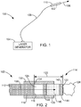
- FIG. 1 is a schematic diagram of an exemplary surgical laser system 100, which includes a laser fiber 102 in accordance with one or more embodiments of the invention.
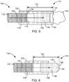
- FIGS. 2-7 are simplified cross-sectional views of exemplary laser fibers 102 in accordance with embodiments of the invention.
- FIG. 4 is a simplified cross-sectional view of a fiber tip of FIG. 4 taken generally along line 4-4.
- the system 100 comprises a laser generator 104 that generates laser energy 106 and a waveguide 108 optically coupling the laser generator 104 to the laser fiber 102.
- the laser fiber 102 either includes the waveguide 108 or is optically coupled to the waveguide 108.
- the laser energy 106 is discharged from a distal end of the laser fiber 102, i.e., the end of the laser fiber 102 that is adjacent to the treatment site of a patient, and can be used to perform a desired medical laser procedure, such as tissue ablation, or urinary or kidney stone fragmentation.
- the system 100 includes a probe 110 ( FIG. 1 ), in which at least a distal end of the laser fiber 102 is supported.
- the laser generator 104 comprises one or more conventional laser sources, such as laser resonators, that produce the laser energy 106 having desired properties.
- the system 100 produces the laser energy 106 in the form of a pulse train or continuous wave.
- the laser generator 102 includes Q-switched laser rods to produce the laser energy 106, such as, for example, a holmium doped yttrium aluminium garnet (Ho:YAG) laser rod, a thulium doped yttrium aluminium garnet (Tm:YAG) laser rod, or other conventional laser rod suitable for producing the desired laser energy 106.
- the laser energy 106 has a power of approximately 1-50W, a pulse repetition frequency of 1-2000Hz, and an energy level of 1mJ-5J. Laser energy 106 having other parameters may also be used.
- the laser fiber 102 includes an optical fiber 112 and a fiber tip 114.
- the optical fiber 112 includes a terminating end surface 116 at a distal end 118.
- the fiber tip 114 includes a distal terminating end 120 that is spaced a predetermined distance 122 from the terminating end surface 116 of the optical fiber 112.
- the fiber tip 114 operates to protect the distal end 118 of the optical fiber.
- the fiber tip 114 can prevent or reduce damage to the distal end 118 of the optical fiber 112 that can occur during medical laser treatments due to contact between the distal end 118 of the optical fiber 112 and the targeted object for the laser energy 106, such as a calculus (i.e., kidney or bladder stone) 124 or tissue.
- the fiber tip 114 forms a sealed cavity 125 around the terminating end surface 116 of the optical fiber, as shown in FIG. 2 .
- the predetermined distance or spacing 122 is generally set to alleviate/control damage to the distal end 118 of the optical fiber 112, manipulate (focus or diffuse) a shock wave generated during laser lithotripsy, and improve ablation efficiency.
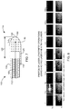
- FIG. 8 shows photos of laser lithotripsy operations using a Ho:YAG laser, and a Tm:YAG laser that show a bubble formation process and oscillations during the laser-stone interaction.
- FIG. 9 is a chart illustrating a relationship between an ablation volume and the spacing 122 between the terminating end surface 116 or fiber tip of the optical fiber 112 and the calculus 124 for a Ho:YAG laser (1.0 J, 10Hz, ⁇ 109 ⁇ s) and a Tm:YAG laser (40mJ, 250Hz, 190ns).
- the chart illustrates that the ablation efficiency for the Ho:YAG laser is higher when the spacing 122 is 0.5mm as compared to when the surface 116 of the optical fiber 112 is in contact with the calculus 124.
- the chart shows that the ablation efficiency of the Tm:YAG laser is similar over the spacing 122 of 0-0.5mm.
- the spacing 122 between the surface 116 of the optical fiber 112 and the targeted object (e.g., calculus 124) provided by the fiber tip 114 can allow for efficient ablation of the targeted object while protecting the optical fiber 122.
- the distance 122 is approximately 0.1-4 mm. In some embodiments, the distance 122 is 0.1mm-1mm.
- the fiber tip 114 is attached to the laser fiber 112, as shown in FIGS. 2 and 5-7 . In some embodiments, this involves attaching the fiber tip 114 to a core of the optical fiber 112, cladding of the optical fiber 112, and/or a jacket surrounding the cladding and core of the optical fiber 112, which are not shown in order to simplify the illustrations. In some embodiments, the fiber tip 114 is removably attached to the optical fiber 112. In some embodiments, the fiber tip 114 may be attached to the distal end 118 of the optical fiber 112 by hand, and may also be detached from the optical fiber 112 by hand.
- the optical fiber 112 may be supported within a fiber support 126, as shown in FIG. 3 .
- the fiber support 126 may be a tubular member through which the optical fiber 112 is inserted.
- the fiber tip 114 attaches directly to the fiber support 126 rather than the optical fiber 112, as shown in FIG. 3 .
- the fiber tip 114 is removably attachable to the fiber support 126.
- the attachment and removal of the fiber tip 114 from the fiber support 126 may be performed by hand.
- the fiber tip 114 includes a sleeve portion 128 that facilitates attachment of the fiber tip 114 to either the optical fiber 112 ( FIG. 2 ) or a fiber support 126 ( FIG. 3 ).
- at least a proximal end 130 of the sleeve portion 128 forms a socket that is configured to receive the distal end 118 of the optical fiber 112 ( FIG. 2 ) or a distal end 132 of the fiber support 126 ( FIG. 3 ).
- the sleeve portion 128 includes a shoulder 134 that is configured to engage the terminating end surface 116 of the optical fiber 112 ( FIG. 2 ) or an end surface 136 of the fiber support 126 ( FIG. 3 ) to position the terminating end 120 of the fiber tip 114 at the desired distance 122 from the terminating end surface 116 of the optical fiber 112.
- the fiber tip 114 includes a transmissive portion 140, through which the laser energy 106 discharged from the terminating end surface 116 of the optical fiber 112 is transmitted. In some embodiments, the laser energy 106 is discharged through the transmissive portion 140 along a longitudinal axis of the optical fiber 112.
- the fiber tip 114 includes a spacer portion 142 that defines the distal terminating end 120 of the fiber tip 114.
- the transmissive portion 140 includes the spacer portion 142, as shown in FIGS. 2 , 3 , 6 and 7 .
- the spacer portion 142 extends distally from the transmissive portion 140, as shown in FIG. 5 .
- the distal terminating end 120 of the spacer portion 142 is annular, as shown in FIG. 5 .
- the distally extending spacer portion 142 may comprise one or more projections.
- the sleeve portion 128 supports the transmissive portion 140 and the spacer portion 142. In some embodiments, the sleeve portion 128 surrounds the distal end 118 of the optical fiber 112. In some embodiments, the sleeve portion 128, the transmissive portion 140, and the spacer portion 142 are formed as a single component, as shown in FIG. 7 .
- components of the fiber tip 114 such as the transmissive portion 140, the spacer portion 142, and/or the sleeve portion 128, are formed of sapphire or hard glass.
- the transmissive portion 140 includes one or more lenses that assist in focusing or diffusing the laser energy 106 that is directed to the targeted object, such as a calculus 124.
- a lens 144 is located at the distal end of the transmissive portion 140, as shown in phantom in FIG. 2 .
- the transmissive portion 140 includes a lens 146 located at a proximal end of the transmissive portion 140, as shown in phantom in FIG. 2 .
- the distal terminating end 120 of the fiber tip 114 includes a convex surface 150, as shown in FIGS. 6 and 7 .
- the surface 150 may operate as the distal lens 144 ( FIG. 2 ).
- the convex surface 150 operates to diffuse the shock wave that occurs during laser lithotripsy to reduce retropulsion of the calculus or stone 124.
- Another embodiment of the invention is directed to a method of fragmenting a calculus using a laser fiber 102 formed in accordance with one or more embodiments of the present invention.
- the calculus 124 is engaged with the terminating end 120 of the fiber tip 114 to position the terminating end surface 116 of the optical fiber 112 at the predetermined distance 122 from the calculus, as shown in FIGS. 2 , 3 and 5 .
- Laser energy 106 is then transmitted through the optical fiber 112 and discharged through the terminating end surface 116.
- the calculus or stone 124 is exposed to the laser energy 106 while the calculus is at the predetermined distance 122 from the terminating end surface 116.
- the calculus is then fragmented responsive to the exposure of the calculus to the laser energy 106 and the shock wave generated thereby.
- fiber tips 114 can be detachably mounted to the laser fiber 102, the fiber tips 114 can be designed for specific procedures, types of calculi, etc. Accordingly, a single laser fiber can be used with different fiber tips 114 to perform multiple different types of procedures more efficiently and with better outcomes.
Landscapes
- Health & Medical Sciences (AREA)
- Physics & Mathematics (AREA)
- Surgery (AREA)
- Life Sciences & Earth Sciences (AREA)
- Optics & Photonics (AREA)
- Heart & Thoracic Surgery (AREA)
- Molecular Biology (AREA)
- Nuclear Medicine, Radiotherapy & Molecular Imaging (AREA)
- Engineering & Computer Science (AREA)
- Biomedical Technology (AREA)
- Electromagnetism (AREA)
- Medical Informatics (AREA)
- Otolaryngology (AREA)
- Animal Behavior & Ethology (AREA)
- General Health & Medical Sciences (AREA)
- Public Health (AREA)
- Veterinary Medicine (AREA)
- Laser Surgery Devices (AREA)
- Optical Couplings Of Light Guides (AREA)
- Radiation-Therapy Devices (AREA)
Description
- Embodiments of the present invention generally relate to laser fibers for performing a medical laser treatment.
- Medical lasers have been used in various practice areas, such as, for example, urology, neurology, otorhinolaryngology, general anesthetic ophthalmology, dentistry, gastroenterology, cardiology, gynecology, and thoracic and orthopedic procedures. Generally, these procedures require precisely controlled delivery of laser energy as part of the treatment protocol.
- The treatment of kidney or bladder calculi or stones, Lithotripsy, is currently achieved through either ESWL (extracorporeal shock wave lithotripsy), surgery, or use of a laser (laser lithotripsy). In the laser application, a holmium doped yttrium aluminium garnet (Ho:YAG) laser rod, or a thulium doped yttrium aluminium garnet (Tm:YAG) laser rod, are used to produce laser energy having a wavelength of around 2000-2100 nm to break up stones of all types. The laser energy is typically in the form of a train of laser pulses, each having long pulse widths, such as approximately a few hundred microseconds. It is believed that a thermo-mechanical mechanism of action is in play for breaking up the stones, namely the laser energy superheats fluid in the vicinity of the stone, and creates a vaporization bubble. The vaporization bubble then expands as a shockwave and destabilizes the stone, causing it to fragment.
- For example, document
JP S61 193653 A - Document
DE 37 27 003 A1 describes an application part for a rigid or flexible endoscope with a viewing channel and a working channel extending in parallel with the viewing channel. The working channel has a guide and a defined stop for an insertable fibreoptic waveguide that can be coupled to a laser light source. The working channel has an optical system for concentrating the laser light emerging from the fibreoptic waveguide onto a punctiform region. That part of the working channel which surrounds the punctiform region is designed as a shock wave reflector. Furthermore, there is a rinsing channel whose outlet orifice is directed at least partially onto the light emergence area of the optical system. - Document
WO 91/05332 A - Document
US 5 944 687 (A ) describes an optically activated transducer for generating acoustic vibrations in a biological medium. The transducer is located at the end of a fiber optic which may be located within a catheter. Energy for operating the transducer is provided optically by laser light transmitted through the fiber optic to the transducer. Pulsed laser light is absorbed in the working fluid of the transducer to generate a thermal pressure and consequent adiabatic expansion of the transducer head such that it does work against the ambient medium. The transducer returns to its original state by a process of thermal cooling. The motion of the transducer within the ambient medium couples acoustic energy into the medium. By pulsing the laser at a high repetition rate (which may vary from CW to 100 kHz) an ultrasonic radiation field can be established locally in the medium. This method of producing ultrasonic vibrations can be used in vivo for the treatment of stroke-related conditions in humans, particularly for dissolving thrombus. The catheter may also incorporate anti-thrombolytic drug treatments as an adjunct therapy and it may be operated in conjunction with ultrasonic detection equipment for imaging and feedback control. - Document
DE 38 36 337 A1 describes a method and a device for recording shock waves generated intracorporally as a result of a laser-induced break-through of a suitable matter in a rinsing medium for the purpose of crushing objects in organs, vessels or the like, by measuring the pressure of the reflected shock waves. - There is a continuous demand for improvements to laser lithotripsy and other laser procedures, such as improved laser fibers for delivering laser energy to the targeted stone or tissue.
- The invention is as defined in the appended claims. Embodiments of the present invention generally relate to a laser fiber for use in performing a medical laser treatment, such as laser lithotripsy, surgical laser systems utilizing such laser fibers, and methods of performing laser lithotripsy procedures using the laser fibers. In some embodiments, the laser fiber includes an optical fiber and a fiber tip. The optical fiber includes a terminating end surface at a distal end. The fiber tip is positioned at the distal end of the optical fiber and includes a transmissive portion and a spacer portion. Laser energy discharged from the terminating end surface of the optical fiber is transmitted through the transmissive portion. The spacer portion defines a distal terminating end of the fiber tip that is spaced a predetermined distance from the terminating end surface of the optical fiber. The predetermined distance is set for shock wave generation for calculus destruction at the distal terminating end of the fiber tip.
- Embodiments of the surgical laser system include a laser generator and the optical fiber formed in accordance with one or more embodiments. The laser generator is configured to output laser energy that is optically coupled to a proximal end of the optical fiber. The laser energy is transmitted through the optical fiber and is discharged through the terminating end surface of the optical fiber and the fiber tip.
- In some embodiments of a method of fragmenting a calculus, the calculus is engaged with the terminating end of the fiber tip to position the terminating end surface of the optical fiber at the predetermined distance from the calculus. Laser energy is transmitted through the optical fiber. The laser energy is discharged through the terminating end surface of the optical fiber and the calculus is exposed to the laser energy while the calculus is maintained at the predetermined distance from the terminating end surface using the spacer portion. The calculus is fragmented in response to the exposure to the laser energy.
- This Summary is provided to introduce a selection of concepts in a simplified form that are further described below in the Detailed Description. This Summary is not intended to identify key features or essential features of the claimed subject matter, nor is it intended to be used as an aid in determining the scope of the claimed subject matter. The claimed subject matter is not limited to implementations that solve any or all disadvantages noted in the Background.
-
-
FIG. 1 is a schematic diagram of an exemplary surgical laser system in accordance with embodiments of the invention. -
FIGS. 2 and3 are simplified side cross-sectional views of a distal end of exemplary laser fibers in accordance with embodiments of the invention. -
FIG. 4 is a simplified cross-sectional view of a fiber tip ofFIG. 3 taken generally along line 4-4. -
FIGS. 5-7 are simplified side cross-sectional views of a distal end of exemplary laser fibers in accordance with embodiments of the invention. -
FIG. 8 shows photos of laser lithotripsy operations using exemplary lasers. -
FIG. 9 is a chart illustrating a relationship between an ablation volume and a spacing between a terminating end surface or fiber tip of an optical fiber and a calculus for two exemplary lasers. - Embodiments of the present invention generally relate to laser fibers for use in performing a medical laser treatment, such as laser lithotripsy, surgical laser systems utilizing such laser fibers, and methods of performing laser lithotripsy procedures using the laser fibers. Embodiments of the invention are described more fully hereinafter with reference to the accompanying drawings. The various embodiments of the invention may, however, be embodied in many different forms and should not be construed as limited to the embodiments set forth herein. Rather, these embodiments are provided so that this disclosure will be thorough and complete, and will fully convey the scope of the invention to those skilled in the art. Elements that are identified using the same or similar reference characters refer to the same or similar elements.
- The terminology used herein is for the purpose of describing particular embodiments only and is not intended to be limiting of the invention. As used herein, the singular forms "a", "an" and "the" are intended to include the plural forms as well, unless the context clearly indicates otherwise. It will be further understood that the terms "comprises" and/or "comprising," when used in this specification, specify the presence of stated features, integers, steps, operations, elements, and/or components, but do not preclude the presence or addition of one or more other features, integers, steps, operations, elements, components, and/or groups thereof.
- It will be understood that when an element is referred to as being "connected" or "coupled" to another element, it can be directly connected or coupled to the other element or intervening elements may be present. In contrast, if an element is referred to as being "directly connected" or "directly coupled" to another element, there are no intervening elements present.
- It will be understood that, although the terms first, second, etc. may be used herein to describe various elements, these elements should not be limited by these terms. These terms are only used to distinguish one element from another. Thus, a first element could be termed a second element without departing from the teachings of the present invention.
- Unless otherwise defined, all terms (including technical and scientific terms) used herein have the same meaning as commonly understood by one of ordinary skill in the art to which this invention belongs. It will be further understood that terms, such as those defined in commonly used dictionaries, should be interpreted as having a meaning that is consistent with their meaning in the context of the relevant art and will not be interpreted in an idealized or overly formal sense unless expressly so defined herein.
-
FIG. 1 is a schematic diagram of an exemplarysurgical laser system 100, which includes alaser fiber 102 in accordance with one or more embodiments of the invention.FIGS. 2-7 are simplified cross-sectional views ofexemplary laser fibers 102 in accordance with embodiments of the invention.FIG. 4 is a simplified cross-sectional view of a fiber tip ofFIG. 4 taken generally along line 4-4. - In some embodiments, the
system 100 comprises alaser generator 104 that generateslaser energy 106 and awaveguide 108 optically coupling thelaser generator 104 to thelaser fiber 102. Thelaser fiber 102 either includes thewaveguide 108 or is optically coupled to thewaveguide 108. Thelaser energy 106 is discharged from a distal end of thelaser fiber 102, i.e., the end of thelaser fiber 102 that is adjacent to the treatment site of a patient, and can be used to perform a desired medical laser procedure, such as tissue ablation, or urinary or kidney stone fragmentation. In some embodiments, thesystem 100 includes a probe 110 (FIG. 1 ), in which at least a distal end of thelaser fiber 102 is supported. - In some embodiments, the
laser generator 104 comprises one or more conventional laser sources, such as laser resonators, that produce thelaser energy 106 having desired properties. In some embodiments, thesystem 100 produces thelaser energy 106 in the form of a pulse train or continuous wave. In some embodiments, thelaser generator 102 includes Q-switched laser rods to produce thelaser energy 106, such as, for example, a holmium doped yttrium aluminium garnet (Ho:YAG) laser rod, a thulium doped yttrium aluminium garnet (Tm:YAG) laser rod, or other conventional laser rod suitable for producing the desiredlaser energy 106. In some embodiments thelaser energy 106 has a power of approximately 1-50W, a pulse repetition frequency of 1-2000Hz, and an energy level of 1mJ-5J.Laser energy 106 having other parameters may also be used. - In some embodiments, the
laser fiber 102 includes anoptical fiber 112 and afiber tip 114. Theoptical fiber 112 includes a terminatingend surface 116 at adistal end 118. In some embodiments, thefiber tip 114 includes a distal terminatingend 120 that is spaced apredetermined distance 122 from the terminatingend surface 116 of theoptical fiber 112. In some embodiments, thefiber tip 114 operates to protect thedistal end 118 of the optical fiber. For instance, thefiber tip 114 can prevent or reduce damage to thedistal end 118 of theoptical fiber 112 that can occur during medical laser treatments due to contact between thedistal end 118 of theoptical fiber 112 and the targeted object for thelaser energy 106, such as a calculus (i.e., kidney or bladder stone) 124 or tissue. In some embodiments, thefiber tip 114 forms a sealedcavity 125 around the terminatingend surface 116 of the optical fiber, as shown inFIG. 2 . - In some embodiments, the predetermined distance or spacing 122 is generally set to alleviate/control damage to the
distal end 118 of theoptical fiber 112, manipulate (focus or diffuse) a shock wave generated during laser lithotripsy, and improve ablation efficiency.FIG. 8 shows photos of laser lithotripsy operations using a Ho:YAG laser, and a Tm:YAG laser that show a bubble formation process and oscillations during the laser-stone interaction.FIG. 9 is a chart illustrating a relationship between an ablation volume and thespacing 122 between the terminatingend surface 116 or fiber tip of theoptical fiber 112 and thecalculus 124 for a Ho:YAG laser (1.0 J, 10Hz, ∼109µs) and a Tm:YAG laser (40mJ, 250Hz, 190ns). The chart illustrates that the ablation efficiency for the Ho:YAG laser is higher when thespacing 122 is 0.5mm as compared to when thesurface 116 of theoptical fiber 112 is in contact with thecalculus 124. Additionally, the chart shows that the ablation efficiency of the Tm:YAG laser is similar over the spacing 122 of 0-0.5mm. Thus, the spacing 122 between thesurface 116 of theoptical fiber 112 and the targeted object (e.g., calculus 124) provided by thefiber tip 114 can allow for efficient ablation of the targeted object while protecting theoptical fiber 122. In some embodiments, thedistance 122 is approximately 0.1-4 mm. In some embodiments, thedistance 122 is 0.1mm-1mm. - In some embodiments, the
fiber tip 114 is attached to thelaser fiber 112, as shown inFIGS. 2 and5-7 . In some embodiments, this involves attaching thefiber tip 114 to a core of theoptical fiber 112, cladding of theoptical fiber 112, and/or a jacket surrounding the cladding and core of theoptical fiber 112, which are not shown in order to simplify the illustrations. In some embodiments, thefiber tip 114 is removably attached to theoptical fiber 112. In some embodiments, thefiber tip 114 may be attached to thedistal end 118 of theoptical fiber 112 by hand, and may also be detached from theoptical fiber 112 by hand. - In some embodiments, the
optical fiber 112 may be supported within afiber support 126, as shown inFIG. 3 . Thefiber support 126 may be a tubular member through which theoptical fiber 112 is inserted. In some embodiments, thefiber tip 114 attaches directly to thefiber support 126 rather than theoptical fiber 112, as shown inFIG. 3 . In some embodiments, thefiber tip 114 is removably attachable to thefiber support 126. In some embodiments, the attachment and removal of thefiber tip 114 from thefiber support 126 may be performed by hand. - In some embodiments, the
fiber tip 114 includes asleeve portion 128 that facilitates attachment of thefiber tip 114 to either the optical fiber 112 (FIG. 2 ) or a fiber support 126 (FIG. 3 ). In some embodiments, at least aproximal end 130 of thesleeve portion 128 forms a socket that is configured to receive thedistal end 118 of the optical fiber 112 (FIG. 2 ) or adistal end 132 of the fiber support 126 (FIG. 3 ). In some embodiments, thesleeve portion 128 includes ashoulder 134 that is configured to engage the terminatingend surface 116 of the optical fiber 112 (FIG. 2 ) or anend surface 136 of the fiber support 126 (FIG. 3 ) to position the terminatingend 120 of thefiber tip 114 at the desireddistance 122 from the terminatingend surface 116 of theoptical fiber 112. - In some embodiments, the
fiber tip 114 includes atransmissive portion 140, through which thelaser energy 106 discharged from the terminatingend surface 116 of theoptical fiber 112 is transmitted. In some embodiments, thelaser energy 106 is discharged through thetransmissive portion 140 along a longitudinal axis of theoptical fiber 112. - In some embodiments, the
fiber tip 114 includes aspacer portion 142 that defines the distal terminatingend 120 of thefiber tip 114. In some embodiments, thetransmissive portion 140 includes thespacer portion 142, as shown inFIGS. 2 ,3 ,6 and7 . In some embodiments, thespacer portion 142 extends distally from thetransmissive portion 140, as shown inFIG. 5 . In some embodiments, the distal terminatingend 120 of thespacer portion 142 is annular, as shown inFIG. 5 . In other embodiments, the distally extendingspacer portion 142 may comprise one or more projections. - In some embodiments, the
sleeve portion 128 supports thetransmissive portion 140 and thespacer portion 142. In some embodiments, thesleeve portion 128 surrounds thedistal end 118 of theoptical fiber 112. In some embodiments, thesleeve portion 128, thetransmissive portion 140, and thespacer portion 142 are formed as a single component, as shown inFIG. 7 . - In some embodiments, components of the
fiber tip 114, such as thetransmissive portion 140, thespacer portion 142, and/or thesleeve portion 128, are formed of sapphire or hard glass. - In some embodiments, the
transmissive portion 140 includes one or more lenses that assist in focusing or diffusing thelaser energy 106 that is directed to the targeted object, such as acalculus 124. In some embodiments, alens 144 is located at the distal end of thetransmissive portion 140, as shown in phantom inFIG. 2 . In some embodiments, thetransmissive portion 140 includes alens 146 located at a proximal end of thetransmissive portion 140, as shown in phantom inFIG. 2 . - In some embodiments, the distal terminating
end 120 of thefiber tip 114 includes aconvex surface 150, as shown inFIGS. 6 and7 . Thesurface 150 may operate as the distal lens 144 (FIG. 2 ). In some embodiments, theconvex surface 150 operates to diffuse the shock wave that occurs during laser lithotripsy to reduce retropulsion of the calculus orstone 124. - Another embodiment of the invention is directed to a method of fragmenting a calculus using a
laser fiber 102 formed in accordance with one or more embodiments of the present invention. In the method, thecalculus 124 is engaged with the terminatingend 120 of thefiber tip 114 to position the terminatingend surface 116 of theoptical fiber 112 at thepredetermined distance 122 from the calculus, as shown inFIGS. 2 ,3 and5 .Laser energy 106 is then transmitted through theoptical fiber 112 and discharged through the terminatingend surface 116. The calculus orstone 124 is exposed to thelaser energy 106 while the calculus is at thepredetermined distance 122 from the terminatingend surface 116. The calculus is then fragmented responsive to the exposure of the calculus to thelaser energy 106 and the shock wave generated thereby. - Additionally, because
fiber tips 114 according to the embodiments of the present invention can be detachably mounted to thelaser fiber 102, thefiber tips 114 can be designed for specific procedures, types of calculi, etc. Accordingly, a single laser fiber can be used withdifferent fiber tips 114 to perform multiple different types of procedures more efficiently and with better outcomes. - The embodiments aspects and examples which do not fall within the scope of the claims are provided for illustrative purpose only and do not form part of the present invention. The invention is defined in the claims as follows.
Claims (13)
- A laser fiber (102) for performing laser lithotripsy comprising:an optical fiber (112) having a distal end (118) and a terminating end surface (116) at the distal end (118); anda fiber tip (114) at the distal end (118) of the optical fiber (112), the fiber tip (114) including a transmissive portion (140), through which laser energy discharged from the terminating end surface (116) of the optical fiber (112) is transmitted, and a spacer portion (142) defining a distal terminating end (120) of the fiber tip (114) that is spaced a predetermined distance (122) from the terminating end surface (116) of the optical fiber (112);wherein the predetermined distance (122) is set for shock wave generation for calculus destruction at the distal terminating end (120) of the fiber tip (114),wherein the predetermined distance (122) is between 0.1 mm and 4 mm,wherein the fiber tip (114) forms a sealed cavity (125) around the terminating end surface (116) of the optical fiber (112).
- The laser fiber (102) according to claim 1, wherein the fiber tip (114) is attached to the distal end (118) of the optical fiber (112).
- The laser fiber (102) according to claim 2, wherein the fiber tip (114) is removably attached to the distal end (118) of the optical fiber (112).
- The laser fiber (102) according to claim 1, wherein the optical fiber (112) is contained within a fiber support (126), and the fiber tip (114) is attached to the fiber support (126).
- The laser fiber (102) according to claim 4, wherein the fiber tip (114) is removably attached to the fiber support (126).
- The laser fiber (102) according to any of claims 1 to 5, wherein the transmissive portion (140) includes the spacer portion (142).
- The laser fiber (102) according to any of claims 1 to 5, wherein the spacer portion (142) extends distally from the transmissive portion (140).
- The laser fiber (102) according to any of claims 1 to 7, wherein the fiber tip (114) comprises a sleeve portion (128) having a proximal end (130) that surrounds the distal end (118) of the optical fiber (112) and supports the transmissive portion (140) and the spacer portion (142).
- The laser fiber (102) according to any of claims 1 to 8, wherein the transmissive portion (140) comprises a lens (144, 146) that focuses laser energy discharged from the terminating end surface (116) of the optical fiber (112).
- The laser fiber (102) according to claim 9, wherein the lens (146) is positioned at a proximal end of the transmissive portion (140).
- The laser fiber (102) according to claim 9, wherein the lens (144) is positioned at a distal end of the transmissive portion (140).
- The laser fiber (102) according to any of claims 1 to 11, wherein the distal terminating end (120) of the fiber tip (114) has a convex surface.
- A surgical laser system comprising a laser fiber (102) according to any of claims 1 to 12 and a laser generator (104) configured to output laser energy that is optically coupled to a proximal end of the optical fiber (112), wherein the laser energy is transmitted through the optical fiber (112) and is discharged through the terminating end surface (116) of the optical fiber (112) and the fiber tip (114).
Priority Applications (2)
| Application Number | Priority Date | Filing Date | Title |
|---|---|---|---|
| EP24179752.1A EP4413938A3 (en) | 2014-09-24 | 2015-09-23 | Laser lithotripsy system |
| EP20157020.7A EP3673853B1 (en) | 2014-09-24 | 2015-09-23 | Laser lithotripsy system |
Applications Claiming Priority (2)
| Application Number | Priority Date | Filing Date | Title |
|---|---|---|---|
| US201462054582P | 2014-09-24 | 2014-09-24 | |
| PCT/US2015/051687 WO2016049160A1 (en) | 2014-09-24 | 2015-09-23 | Laser lithotripsy system |
Related Child Applications (3)
| Application Number | Title | Priority Date | Filing Date |
|---|---|---|---|
| EP24179752.1A Division EP4413938A3 (en) | 2014-09-24 | 2015-09-23 | Laser lithotripsy system |
| EP20157020.7A Division EP3673853B1 (en) | 2014-09-24 | 2015-09-23 | Laser lithotripsy system |
| EP20157020.7A Division-Into EP3673853B1 (en) | 2014-09-24 | 2015-09-23 | Laser lithotripsy system |
Publications (2)
| Publication Number | Publication Date |
|---|---|
| EP3197381A1 EP3197381A1 (en) | 2017-08-02 |
| EP3197381B1 true EP3197381B1 (en) | 2020-03-25 |
Family
ID=54252430
Family Applications (3)
| Application Number | Title | Priority Date | Filing Date |
|---|---|---|---|
| EP24179752.1A Pending EP4413938A3 (en) | 2014-09-24 | 2015-09-23 | Laser lithotripsy system |
| EP20157020.7A Active EP3673853B1 (en) | 2014-09-24 | 2015-09-23 | Laser lithotripsy system |
| EP15775348.4A Active EP3197381B1 (en) | 2014-09-24 | 2015-09-23 | Laser lithotripsy system |
Family Applications Before (2)
| Application Number | Title | Priority Date | Filing Date |
|---|---|---|---|
| EP24179752.1A Pending EP4413938A3 (en) | 2014-09-24 | 2015-09-23 | Laser lithotripsy system |
| EP20157020.7A Active EP3673853B1 (en) | 2014-09-24 | 2015-09-23 | Laser lithotripsy system |
Country Status (4)
| Country | Link |
|---|---|
| US (1) | US20220370130A1 (en) |
| EP (3) | EP4413938A3 (en) |
| CN (1) | CN106604690A (en) |
| WO (1) | WO2016049160A1 (en) |
Families Citing this family (2)
| Publication number | Priority date | Publication date | Assignee | Title |
|---|---|---|---|---|
| US10646276B2 (en) | 2016-05-18 | 2020-05-12 | Gyrus Acmi, Inc. | Apparatus for laser lithotripsy |
| US10405923B2 (en) | 2016-08-12 | 2019-09-10 | Boston Scientific Scimed, Inc. | Systems, devices, and related methods for laser lithotripsy |
Citations (5)
| Publication number | Priority date | Publication date | Assignee | Title |
|---|---|---|---|---|
| JPS61193653A (en) * | 1985-02-22 | 1986-08-28 | メツセルシユミツト‐ベルコウ‐ブローム・ゲゼルシヤフト・ミト・ベシユレンクテル・ハフツング | Method and apparatus for crushing solid matter |
| DE3727003A1 (en) * | 1986-08-13 | 1988-02-25 | Messerschmitt Boelkow Blohm | Application part for a rigid or flexible endoscope |
| DE3836337A1 (en) * | 1988-10-25 | 1990-04-26 | Meessen Stephan Dr B | Method and device for recording intracorporally generated, laser-induced shock waves |
| WO1991005332A1 (en) * | 1989-10-07 | 1991-04-18 | Laser-Medizin-Zentrum Gmbh Berlin | Process and device for generating laser-induced shock wave |
| US5944687A (en) * | 1996-04-24 | 1999-08-31 | The Regents Of The University Of California | Opto-acoustic transducer for medical applications |
Family Cites Families (12)
| Publication number | Priority date | Publication date | Assignee | Title |
|---|---|---|---|---|
| US5167686A (en) * | 1985-03-06 | 1992-12-01 | C. R. Bard, Inc. | Catheter system for controlled removal by radiant energy of biological obstructions |
| US4850351A (en) * | 1985-05-22 | 1989-07-25 | C. R. Bard, Inc. | Wire guided laser catheter |
| US6110167A (en) * | 1990-10-31 | 2000-08-29 | Premier Laser Systems, Inc. | Contact tip for laser surgery |
| US5342355A (en) * | 1992-10-19 | 1994-08-30 | Laser Centers Of America | Energy delivering cap element for end of optic fiber conveying laser energy |
| US5562657A (en) * | 1994-09-19 | 1996-10-08 | Griffin; Stephen E. | Side fire laser catheter method and apparatus |
| US5815623A (en) * | 1996-01-18 | 1998-09-29 | Methode Electronics, Inc. | Optical package with alignment means and method of assembling an optical package |
| DE10342016A1 (en) * | 2003-09-11 | 2005-04-14 | Siemens Ag | Lithotripsy device |
| US20050113814A1 (en) * | 2003-11-24 | 2005-05-26 | Loeb Marvin P. | Apparatus and method for limiting the re-use of fiber optic, laser energy delivery devices |
| US20070027443A1 (en) * | 2005-06-29 | 2007-02-01 | Ondine International, Ltd. | Hand piece for the delivery of light and system employing the hand piece |
| US8679103B2 (en) * | 2008-12-22 | 2014-03-25 | Valam Corporation | Two step mammalian biofilm treatment processes and systems |
| US20110255828A1 (en) * | 2008-12-22 | 2011-10-20 | Ams Research Corporation | Sapphire-based delivery tip for optic fiber |
| CN102370520B (en) * | 2011-11-03 | 2013-09-18 | 温海涛 | Laser gravel fixing forceps |
-
2015
- 2015-09-23 EP EP24179752.1A patent/EP4413938A3/en active Pending
- 2015-09-23 WO PCT/US2015/051687 patent/WO2016049160A1/en active Application Filing
- 2015-09-23 EP EP20157020.7A patent/EP3673853B1/en active Active
- 2015-09-23 CN CN201580047794.XA patent/CN106604690A/en active Pending
- 2015-09-23 EP EP15775348.4A patent/EP3197381B1/en active Active
-
2022
- 2022-08-03 US US17/817,254 patent/US20220370130A1/en active Pending
Patent Citations (5)
| Publication number | Priority date | Publication date | Assignee | Title |
|---|---|---|---|---|
| JPS61193653A (en) * | 1985-02-22 | 1986-08-28 | メツセルシユミツト‐ベルコウ‐ブローム・ゲゼルシヤフト・ミト・ベシユレンクテル・ハフツング | Method and apparatus for crushing solid matter |
| DE3727003A1 (en) * | 1986-08-13 | 1988-02-25 | Messerschmitt Boelkow Blohm | Application part for a rigid or flexible endoscope |
| DE3836337A1 (en) * | 1988-10-25 | 1990-04-26 | Meessen Stephan Dr B | Method and device for recording intracorporally generated, laser-induced shock waves |
| WO1991005332A1 (en) * | 1989-10-07 | 1991-04-18 | Laser-Medizin-Zentrum Gmbh Berlin | Process and device for generating laser-induced shock wave |
| US5944687A (en) * | 1996-04-24 | 1999-08-31 | The Regents Of The University Of California | Opto-acoustic transducer for medical applications |
Also Published As
| Publication number | Publication date |
|---|---|
| US20220370130A1 (en) | 2022-11-24 |
| EP3197381A1 (en) | 2017-08-02 |
| EP3673853B1 (en) | 2024-06-12 |
| WO2016049160A1 (en) | 2016-03-31 |
| EP4413938A3 (en) | 2024-09-18 |
| EP3673853A1 (en) | 2020-07-01 |
| EP4413938A2 (en) | 2024-08-14 |
| CN106604690A (en) | 2017-04-26 |
Similar Documents
| Publication | Publication Date | Title |
|---|---|---|
| US11439465B2 (en) | Surgical laser systems and laser lithotripsy techniques | |
| EP0959782B1 (en) | Opto-acoustic thrombolysis | |
| US5059200A (en) | Laser lithotripsy | |
| US8409176B2 (en) | Method and device for laser lithotripsy | |
| KR101529367B1 (en) | Laser induced vapor/plasma mediated medical procedures and device | |
| US6491685B2 (en) | Laser and acoustic lens for lithotripsy | |
| US20020045890A1 (en) | Opto-acoustic thrombolysis | |
| US5151098A (en) | Apparatus for controlled tissue ablation | |
| US4887600A (en) | Use of lasers to break down objects | |
| US11648150B2 (en) | Laser apparatus for treatment of a cataractous lens | |
| Grocela et al. | Intracorporeal lithotripsy: instrumentation and development | |
| US7690382B2 (en) | System and method for salivary stones removal and joint arthroscopy | |
| US20220370130A1 (en) | Surgical laser systems and laser lithotripsy techniques | |
| JP2002537017A (en) | Laser lithotripsy device using suction | |
| WO1991010403A1 (en) | Method and apparatus for fragmentation of hard substances | |
| EP0220304B1 (en) | Use of lasers to break down objects | |
| Hofmann et al. | First clinical experience with a Q-switched neodymium: YAG laser for urinary calculi | |
| US5135534A (en) | Laser lithotripsy | |
| US20190321104A1 (en) | Method of reducing retro-repulsion during laser lithotripsy | |
| US20140336626A1 (en) | Medical assembly using short pulse fiber laser | |
| Celliers et al. | Opto-acoustic thrombolysis | |
| Thomas et al. | Laser induced shock wave lithotripsy | |
| Frank et al. | Application systems for the intracorporal laser-induced shockwave lithotripsy using the Nd: YAG Q-switched laser |
Legal Events
| Date | Code | Title | Description |
|---|---|---|---|
| STAA | Information on the status of an ep patent application or granted ep patent |
Free format text: STATUS: THE INTERNATIONAL PUBLICATION HAS BEEN MADE |
|
| PUAI | Public reference made under article 153(3) epc to a published international application that has entered the european phase |
Free format text: ORIGINAL CODE: 0009012 |
|
| STAA | Information on the status of an ep patent application or granted ep patent |
Free format text: STATUS: REQUEST FOR EXAMINATION WAS MADE |
|
| 17P | Request for examination filed |
Effective date: 20170420 |
|
| AK | Designated contracting states |
Kind code of ref document: A1 Designated state(s): AL AT BE BG CH CY CZ DE DK EE ES FI FR GB GR HR HU IE IS IT LI LT LU LV MC MK MT NL NO PL PT RO RS SE SI SK SM TR |
|
| AX | Request for extension of the european patent |
Extension state: BA ME |
|
| DAV | Request for validation of the european patent (deleted) | ||
| DAX | Request for extension of the european patent (deleted) | ||
| STAA | Information on the status of an ep patent application or granted ep patent |
Free format text: STATUS: EXAMINATION IS IN PROGRESS |
|
| 17Q | First examination report despatched |
Effective date: 20180515 |
|
| GRAP | Despatch of communication of intention to grant a patent |
Free format text: ORIGINAL CODE: EPIDOSNIGR1 |
|
| STAA | Information on the status of an ep patent application or granted ep patent |
Free format text: STATUS: GRANT OF PATENT IS INTENDED |
|
| INTG | Intention to grant announced |
Effective date: 20191014 |
|
| GRAS | Grant fee paid |
Free format text: ORIGINAL CODE: EPIDOSNIGR3 |
|
| GRAA | (expected) grant |
Free format text: ORIGINAL CODE: 0009210 |
|
| STAA | Information on the status of an ep patent application or granted ep patent |
Free format text: STATUS: THE PATENT HAS BEEN GRANTED |
|
| AK | Designated contracting states |
Kind code of ref document: B1 Designated state(s): AL AT BE BG CH CY CZ DE DK EE ES FI FR GB GR HR HU IE IS IT LI LT LU LV MC MK MT NL NO PL PT RO RS SE SI SK SM TR |
|
| REG | Reference to a national code |
Ref country code: GB Ref legal event code: FG4D |
|
| REG | Reference to a national code |
Ref country code: DE Ref legal event code: R096 Ref document number: 602015049438 Country of ref document: DE |
|
| REG | Reference to a national code |
Ref country code: AT Ref legal event code: REF Ref document number: 1247672 Country of ref document: AT Kind code of ref document: T Effective date: 20200415 Ref country code: IE Ref legal event code: FG4D |
|
| REG | Reference to a national code |
Ref country code: NL Ref legal event code: FP |
|
| PG25 | Lapsed in a contracting state [announced via postgrant information from national office to epo] |
Ref country code: RS Free format text: LAPSE BECAUSE OF FAILURE TO SUBMIT A TRANSLATION OF THE DESCRIPTION OR TO PAY THE FEE WITHIN THE PRESCRIBED TIME-LIMIT Effective date: 20200325 Ref country code: FI Free format text: LAPSE BECAUSE OF FAILURE TO SUBMIT A TRANSLATION OF THE DESCRIPTION OR TO PAY THE FEE WITHIN THE PRESCRIBED TIME-LIMIT Effective date: 20200325 Ref country code: NO Free format text: LAPSE BECAUSE OF FAILURE TO SUBMIT A TRANSLATION OF THE DESCRIPTION OR TO PAY THE FEE WITHIN THE PRESCRIBED TIME-LIMIT Effective date: 20200625 |
|
| PG25 | Lapsed in a contracting state [announced via postgrant information from national office to epo] |
Ref country code: SE Free format text: LAPSE BECAUSE OF FAILURE TO SUBMIT A TRANSLATION OF THE DESCRIPTION OR TO PAY THE FEE WITHIN THE PRESCRIBED TIME-LIMIT Effective date: 20200325 Ref country code: LV Free format text: LAPSE BECAUSE OF FAILURE TO SUBMIT A TRANSLATION OF THE DESCRIPTION OR TO PAY THE FEE WITHIN THE PRESCRIBED TIME-LIMIT Effective date: 20200325 Ref country code: BG Free format text: LAPSE BECAUSE OF FAILURE TO SUBMIT A TRANSLATION OF THE DESCRIPTION OR TO PAY THE FEE WITHIN THE PRESCRIBED TIME-LIMIT Effective date: 20200625 Ref country code: GR Free format text: LAPSE BECAUSE OF FAILURE TO SUBMIT A TRANSLATION OF THE DESCRIPTION OR TO PAY THE FEE WITHIN THE PRESCRIBED TIME-LIMIT Effective date: 20200626 Ref country code: HR Free format text: LAPSE BECAUSE OF FAILURE TO SUBMIT A TRANSLATION OF THE DESCRIPTION OR TO PAY THE FEE WITHIN THE PRESCRIBED TIME-LIMIT Effective date: 20200325 |
|
| REG | Reference to a national code |
Ref country code: LT Ref legal event code: MG4D |
|
| PG25 | Lapsed in a contracting state [announced via postgrant information from national office to epo] |
Ref country code: SK Free format text: LAPSE BECAUSE OF FAILURE TO SUBMIT A TRANSLATION OF THE DESCRIPTION OR TO PAY THE FEE WITHIN THE PRESCRIBED TIME-LIMIT Effective date: 20200325 Ref country code: SM Free format text: LAPSE BECAUSE OF FAILURE TO SUBMIT A TRANSLATION OF THE DESCRIPTION OR TO PAY THE FEE WITHIN THE PRESCRIBED TIME-LIMIT Effective date: 20200325 Ref country code: IS Free format text: LAPSE BECAUSE OF FAILURE TO SUBMIT A TRANSLATION OF THE DESCRIPTION OR TO PAY THE FEE WITHIN THE PRESCRIBED TIME-LIMIT Effective date: 20200725 Ref country code: PT Free format text: LAPSE BECAUSE OF FAILURE TO SUBMIT A TRANSLATION OF THE DESCRIPTION OR TO PAY THE FEE WITHIN THE PRESCRIBED TIME-LIMIT Effective date: 20200818 Ref country code: EE Free format text: LAPSE BECAUSE OF FAILURE TO SUBMIT A TRANSLATION OF THE DESCRIPTION OR TO PAY THE FEE WITHIN THE PRESCRIBED TIME-LIMIT Effective date: 20200325 Ref country code: LT Free format text: LAPSE BECAUSE OF FAILURE TO SUBMIT A TRANSLATION OF THE DESCRIPTION OR TO PAY THE FEE WITHIN THE PRESCRIBED TIME-LIMIT Effective date: 20200325 Ref country code: CZ Free format text: LAPSE BECAUSE OF FAILURE TO SUBMIT A TRANSLATION OF THE DESCRIPTION OR TO PAY THE FEE WITHIN THE PRESCRIBED TIME-LIMIT Effective date: 20200325 Ref country code: RO Free format text: LAPSE BECAUSE OF FAILURE TO SUBMIT A TRANSLATION OF THE DESCRIPTION OR TO PAY THE FEE WITHIN THE PRESCRIBED TIME-LIMIT Effective date: 20200325 |
|
| REG | Reference to a national code |
Ref country code: AT Ref legal event code: MK05 Ref document number: 1247672 Country of ref document: AT Kind code of ref document: T Effective date: 20200325 |
|
| REG | Reference to a national code |
Ref country code: DE Ref legal event code: R097 Ref document number: 602015049438 Country of ref document: DE |
|
| PG25 | Lapsed in a contracting state [announced via postgrant information from national office to epo] |
Ref country code: AT Free format text: LAPSE BECAUSE OF FAILURE TO SUBMIT A TRANSLATION OF THE DESCRIPTION OR TO PAY THE FEE WITHIN THE PRESCRIBED TIME-LIMIT Effective date: 20200325 Ref country code: DK Free format text: LAPSE BECAUSE OF FAILURE TO SUBMIT A TRANSLATION OF THE DESCRIPTION OR TO PAY THE FEE WITHIN THE PRESCRIBED TIME-LIMIT Effective date: 20200325 Ref country code: IT Free format text: LAPSE BECAUSE OF FAILURE TO SUBMIT A TRANSLATION OF THE DESCRIPTION OR TO PAY THE FEE WITHIN THE PRESCRIBED TIME-LIMIT Effective date: 20200325 Ref country code: ES Free format text: LAPSE BECAUSE OF FAILURE TO SUBMIT A TRANSLATION OF THE DESCRIPTION OR TO PAY THE FEE WITHIN THE PRESCRIBED TIME-LIMIT Effective date: 20200325 |
|
| PLBE | No opposition filed within time limit |
Free format text: ORIGINAL CODE: 0009261 |
|
| STAA | Information on the status of an ep patent application or granted ep patent |
Free format text: STATUS: NO OPPOSITION FILED WITHIN TIME LIMIT |
|
| PG25 | Lapsed in a contracting state [announced via postgrant information from national office to epo] |
Ref country code: PL Free format text: LAPSE BECAUSE OF FAILURE TO SUBMIT A TRANSLATION OF THE DESCRIPTION OR TO PAY THE FEE WITHIN THE PRESCRIBED TIME-LIMIT Effective date: 20200325 |
|
| 26N | No opposition filed |
Effective date: 20210112 |
|
| PG25 | Lapsed in a contracting state [announced via postgrant information from national office to epo] |
Ref country code: MC Free format text: LAPSE BECAUSE OF FAILURE TO SUBMIT A TRANSLATION OF THE DESCRIPTION OR TO PAY THE FEE WITHIN THE PRESCRIBED TIME-LIMIT Effective date: 20200325 |
|
| REG | Reference to a national code |
Ref country code: CH Ref legal event code: PL |
|
| PG25 | Lapsed in a contracting state [announced via postgrant information from national office to epo] |
Ref country code: SI Free format text: LAPSE BECAUSE OF FAILURE TO SUBMIT A TRANSLATION OF THE DESCRIPTION OR TO PAY THE FEE WITHIN THE PRESCRIBED TIME-LIMIT Effective date: 20200325 |
|
| REG | Reference to a national code |
Ref country code: BE Ref legal event code: MM Effective date: 20200930 |
|
| PG25 | Lapsed in a contracting state [announced via postgrant information from national office to epo] |
Ref country code: LU Free format text: LAPSE BECAUSE OF NON-PAYMENT OF DUE FEES Effective date: 20200923 |
|
| PG25 | Lapsed in a contracting state [announced via postgrant information from national office to epo] |
Ref country code: FR Free format text: LAPSE BECAUSE OF NON-PAYMENT OF DUE FEES Effective date: 20200930 |
|
| PG25 | Lapsed in a contracting state [announced via postgrant information from national office to epo] |
Ref country code: CH Free format text: LAPSE BECAUSE OF NON-PAYMENT OF DUE FEES Effective date: 20200930 Ref country code: BE Free format text: LAPSE BECAUSE OF NON-PAYMENT OF DUE FEES Effective date: 20200930 Ref country code: LI Free format text: LAPSE BECAUSE OF NON-PAYMENT OF DUE FEES Effective date: 20200930 |
|
| PG25 | Lapsed in a contracting state [announced via postgrant information from national office to epo] |
Ref country code: TR Free format text: LAPSE BECAUSE OF FAILURE TO SUBMIT A TRANSLATION OF THE DESCRIPTION OR TO PAY THE FEE WITHIN THE PRESCRIBED TIME-LIMIT Effective date: 20200325 Ref country code: MT Free format text: LAPSE BECAUSE OF FAILURE TO SUBMIT A TRANSLATION OF THE DESCRIPTION OR TO PAY THE FEE WITHIN THE PRESCRIBED TIME-LIMIT Effective date: 20200325 Ref country code: CY Free format text: LAPSE BECAUSE OF FAILURE TO SUBMIT A TRANSLATION OF THE DESCRIPTION OR TO PAY THE FEE WITHIN THE PRESCRIBED TIME-LIMIT Effective date: 20200325 |
|
| PG25 | Lapsed in a contracting state [announced via postgrant information from national office to epo] |
Ref country code: MK Free format text: LAPSE BECAUSE OF FAILURE TO SUBMIT A TRANSLATION OF THE DESCRIPTION OR TO PAY THE FEE WITHIN THE PRESCRIBED TIME-LIMIT Effective date: 20200325 Ref country code: AL Free format text: LAPSE BECAUSE OF FAILURE TO SUBMIT A TRANSLATION OF THE DESCRIPTION OR TO PAY THE FEE WITHIN THE PRESCRIBED TIME-LIMIT Effective date: 20200325 |
|
| P01 | Opt-out of the competence of the unified patent court (upc) registered |
Effective date: 20230530 |
|
| PGFP | Annual fee paid to national office [announced via postgrant information from national office to epo] |
Ref country code: NL Payment date: 20230822 Year of fee payment: 9 |
|
| PGFP | Annual fee paid to national office [announced via postgrant information from national office to epo] |
Ref country code: IE Payment date: 20230823 Year of fee payment: 9 Ref country code: GB Payment date: 20230823 Year of fee payment: 9 |
|
| PGFP | Annual fee paid to national office [announced via postgrant information from national office to epo] |
Ref country code: DE Payment date: 20230822 Year of fee payment: 9 |