EP4559622A1 - Dispositif de polissage de surfaces sphériques de lentilles et procédé de polissage de surfaces sphériques de lentilles - Google Patents
Dispositif de polissage de surfaces sphériques de lentilles et procédé de polissage de surfaces sphériques de lentilles Download PDFInfo
- Publication number
- EP4559622A1 EP4559622A1 EP23211964.4A EP23211964A EP4559622A1 EP 4559622 A1 EP4559622 A1 EP 4559622A1 EP 23211964 A EP23211964 A EP 23211964A EP 4559622 A1 EP4559622 A1 EP 4559622A1
- Authority
- EP
- European Patent Office
- Prior art keywords
- tool
- spindle
- adapter
- polishing
- lens
- Prior art date
- Legal status (The legal status is an assumption and is not a legal conclusion. Google has not performed a legal analysis and makes no representation as to the accuracy of the status listed.)
- Pending
Links
Images


Classifications
-
- B—PERFORMING OPERATIONS; TRANSPORTING
- B24—GRINDING; POLISHING
- B24B—MACHINES, DEVICES, OR PROCESSES FOR GRINDING OR POLISHING; DRESSING OR CONDITIONING OF ABRADING SURFACES; FEEDING OF GRINDING, POLISHING, OR LAPPING AGENTS
- B24B13/00—Machines or devices designed for grinding or polishing optical surfaces on lenses or surfaces of similar shape on other work; Accessories therefor
- B24B13/01—Specific tools, e.g. bowl-like; Production, dressing or fastening of these tools
-
- B—PERFORMING OPERATIONS; TRANSPORTING
- B24—GRINDING; POLISHING
- B24B—MACHINES, DEVICES, OR PROCESSES FOR GRINDING OR POLISHING; DRESSING OR CONDITIONING OF ABRADING SURFACES; FEEDING OF GRINDING, POLISHING, OR LAPPING AGENTS
- B24B13/00—Machines or devices designed for grinding or polishing optical surfaces on lenses or surfaces of similar shape on other work; Accessories therefor
- B24B13/005—Blocking means, chucks or the like; Alignment devices
-
- B—PERFORMING OPERATIONS; TRANSPORTING
- B24—GRINDING; POLISHING
- B24B—MACHINES, DEVICES, OR PROCESSES FOR GRINDING OR POLISHING; DRESSING OR CONDITIONING OF ABRADING SURFACES; FEEDING OF GRINDING, POLISHING, OR LAPPING AGENTS
- B24B13/00—Machines or devices designed for grinding or polishing optical surfaces on lenses or surfaces of similar shape on other work; Accessories therefor
- B24B13/02—Machines or devices designed for grinding or polishing optical surfaces on lenses or surfaces of similar shape on other work; Accessories therefor by means of tools with abrading surfaces corresponding in shape with the lenses to be made
-
- B—PERFORMING OPERATIONS; TRANSPORTING
- B24—GRINDING; POLISHING
- B24B—MACHINES, DEVICES, OR PROCESSES FOR GRINDING OR POLISHING; DRESSING OR CONDITIONING OF ABRADING SURFACES; FEEDING OF GRINDING, POLISHING, OR LAPPING AGENTS
- B24B41/00—Component parts such as frames, beds, carriages, headstocks
- B24B41/04—Headstocks; Working-spindles; Features relating thereto
- B24B41/042—Balancing mechanisms
-
- B—PERFORMING OPERATIONS; TRANSPORTING
- B24—GRINDING; POLISHING
- B24B—MACHINES, DEVICES, OR PROCESSES FOR GRINDING OR POLISHING; DRESSING OR CONDITIONING OF ABRADING SURFACES; FEEDING OF GRINDING, POLISHING, OR LAPPING AGENTS
- B24B53/00—Devices or means for dressing or conditioning abrasive surfaces
- B24B53/12—Dressing tools; Holders therefor
Definitions
- Polishing occurs through a sliding relative movement between the surface of the workpiece to be processed and a polishing tool designed as a holder for a polishing agent carrier. This, in conjunction with a polishing agent, enables the polishing removal and thus the adjustment or smoothing of the workpiece surface.
- the polishing agent carrier must be malleable in order to accommodate the required workpiece radius. It must also bond well to the tool carrier and must not contain any contaminants that could damage the glass surface. Elastomeric films made of foamed polyurethane, for example, are well suited; their good mechanical and chemical properties largely meet these requirements.
- the requirements for a polishing agent are not directly can be traced back to measurable quantities, so that the selection and mixture of the polishing agent is essentially based on empirical values. Suspensions of finely ground oxides of trivalent and tetravalent metals are predominantly used, although these depend heavily on the material to be machined.
- a tool determines the shape of a workpiece during machining.
- this is not the case to the same extent when polishing glass materials as it is, for example, in metal machining.
- wear-related adaptation of the polishing agent carrier to the surface of the workpiece occurs, so that after machining only a few surfaces the tool radius has changed.
- the target correction of the lens surface quickly falls outside the specified tolerances. This makes it necessary to dress the polishing agent carrier to the required spherical radius at regular intervals during the polishing process, i.e. to adapt it in such a way that the dimensional accuracy and grip of the polishing tool are maintained.
- the dressing of a polishing tool is often performed outside the polishing machine on special dressing machines. These include, for example, lever machines with diamond pellet-coated surface tools, the adjustment of which can only be made empirically. Furthermore, the polishing correction tool must be ground using a specially manufactured tool before the actual correction of the polishing tool can take place. Often, several subsequent adjustments of the polishing tool and, if necessary, the grinding tool are necessary, making this process extremely laborious and very costly. The success of this process depends particularly on the skill and experience of the operator, so specially trained personnel are required. When dressing with surface tools, a separate polishing correction tool must be made for each radius.
- State of the art includes a device and method for polishing spherical lens surfaces.
- This state-of-the-art device is designed as a three-spindle machine. It is a CNC machine tool that has a pivoting unit of one axis with a rotating tool spindle for holding a polishing tool.
- a second feed drive at a fixed distance, houses a rotatably mounted workpiece spindle for holding a lens and a tool spindle, rotatably mounted parallel to the workpiece spindle, for holding a dressing tool, for example, a cup tool. Relative pivoting is possible between the polishing tool and the lens.
- This state-of-the-art process is the so-called "synchrospeed method.”
- the lenses are held by a workpiece chuck.
- This workpiece chuck consists of a guide ring, a base body, and a membrane that is pressurized with compressed air via the workpiece spindle to hold the lens in place.
- This workpiece chuck is connected to the workpiece spindle via a mechanical clamping system.
- there is a tool on the tool spindle side that, according to the state of the art, is approximately twice the diameter of the lens.
- This tool has a coating of polishing film or is made of a material suitable for optical polishing.
- the polishing tool is also firmly connected to the machine's tool spindle via a mechanical clamping system.
- a second spindle equipped with a dressing tool, is located parallel to the workpiece spindle on the three-axis CNC machine.
- This dressing tool is, as is known from practice, a ring-shaped cup tool, which is also firmly connected to the dressing spindle via a mechanical system.
- the state-of-the-art machining process is as follows.
- the dressing spindle and the tool for machining the lens are positioned via the three-axis CNC control system, allowing the tool surface to be machined to the exact radius of the lens to be machined.
- the lens is inserted into the workpiece chuck of the lens holder.
- the actual machining process then begins.
- the CNC-controlled machine moves into a three-axis position, where the lens surface is placed in a very precise orthogonal position relative to the radius center.
- the lens surface is still a small distance from the tool surface. Only after the working pressure is applied to the lens does the lens surface touch the tool. Now the actual machining process begins. Both the workpiece and the tool spindle begin to rotate in a synchronous mode. The speed of the workpiece spindle is controlled in relation to the tool spindle. determined through a calculation process. The speeds are unequal and radius-dependent.
- the lens is removed and measured. Once the desired lens radius has been achieved, series production can begin. If the desired lens radius is not yet achieved, another correction is made using the dressing spindle. This iterative process is repeated until the exact lens parameters are achieved.
- This state-of-the-art CNC machine has the disadvantage of being very expensive. Furthermore, the lens mount must be machined on a separate CNC-controlled grinding machine.
- the technical problem underlying the invention is to provide a device for polishing spherical surfaces of lenses that is inexpensive to construct. Furthermore, a method for polishing spherical surfaces of lenses that is simple and inexpensive to implement is to be provided.
- the device according to the invention for polishing spherical surfaces of lenses made of glass with a rotating driven tool spindle for holding a machining tool is characterized in that the device is designed as a two-spindle machine with a tool spindle and a workpiece spindle and that a holder for the lens or a holder for a dressing tool is arranged on the workpiece spindle.
- the device according to the invention has the advantage that it is designed as a two-spindle machine, and that either the lens holder or, alternatively, the holder for a dressing tool is arranged on the workpiece spindle.
- This allows the prior art three-spindle machine to be reduced to a two-spindle machine, which results in considerable cost savings, since a two-spindle machine is significantly less expensive than a three-spindle machine.
- a spindle adapter is arranged on the tool spindle, and that interchangeable tool adapters can be arranged on the spindle adapter, and that the polishing tool is arranged on a first tool adapter and that the grinding tool is arranged on a second tool adapter.
- a spindle adapter is arranged on the workpiece spindle, and that exchangeable base adapters can be arranged on the spindle adapter, and that a lens holder is arranged on a first base adapter, and that the dressing tool is arranged on a second base adapter.
- This embodiment has the advantage that a spindle adapter, advantageously detachably fixed, for example screwed, is arranged on the workpiece spindle.
- Base adapters are exchangeably arranged on the spindle adapter.
- a lens holder, preferably detachably fixed, advantageously screwed, is advantageously arranged on a first base adapter.
- the dressing tool, preferably detachably fixed, for example screwed, is advantageously arranged on a second base adapter.
- This embodiment has the advantage that various parts can be arranged on the workpiece spindle in a simple manner. can be used, namely the lens holder and the dressing tool.
- the device according to the invention has only two spindles, namely the tool spindle and the workpiece spindle.
- the lens holder located on the workpiece spindle can be machined with a grinding tool.
- the grinding tool is mounted with the tool adapter on the spindle adapter of the tool spindle.
- the tool adapter is detachably arranged on the spindle adapter by means of a magnetic force.
- the base adapter is detachably arranged on the spindle adapter by means of a magnetic force.
- the tool adapters and base adapters are detachably mounted on the spindle adapters of the workpiece spindle or the tool spindle, interchangeability should be easy. If the holding force is implemented as a magnetic force, replacing the tool adapters or base adapters is particularly easy.
- Permanent magnets are particularly advantageous for generating the holding force. Permanent magnets have the advantage that the holding force can be easily overcome, for example, by lever action, to release the adapters from each other. Furthermore, no lines, such as pneumatic, electrical, or hydraulic lines, are required.
- holding forces can also be provided.
- electromagnetic holding forces, pneumatic holding forces, or hydraulic holding forces can be provided. Holding forces are advantageous if automation of the separation of the adapters is desired.
- fresh water is used as a coolant during the processing of the lens holder or the polishing tool.
- a supply line for the coolant is advantageously provided.
- a disposal line is advantageously provided for the return of waste water.
- a recess is arranged in the spindle adapter and a driving pin is arranged in the tool adapter or the base adapter, and that when the tool adapter or the base adapter is arranged on the spindle adapter, the driving pin is arranged in the recess.
- the workpiece spindle and the tool spindle are rotated during the various machining processes of polishing, dressing, or grinding. Since the spindle adapter and the base adapter, or the spindle adapter and the tool adapter, are connected in the axial direction of the spindle by means of a holding force, it must be ensured that the base adapter or the tool adapter also rotates during the rotation of the spindles. This means that the rotation of the spindle adapter must be transferred to the tool adapter or the base adapter.
- a drive pin is advantageously arranged in the tool adapter or the base adapter, and a recess is provided in the spindle adapter. The drive pin The tool adapter or the base adapter is moved when the spindle adapter is rotated.
- a driving pin is arranged in the spindle adapter and a recess is arranged in the tool adapter or the base adapter, and that when the tool adapter or the base adapter is arranged on the spindle adapter, the driving pin is arranged in the recess.
- This design ensures that the rotation of the spindle adapter is transferred to the tool adapter or the base adapter.
- a recess is arranged between the spindle adapter and the tool adapter, or between the spindle adapter and the base adapter.
- This embodiment has the advantage that a tool, such as a screwdriver, can be inserted into the recess to release the tool adapter or the base adapter from the respective spindle adapter.
- a tool such as a screwdriver
- This embodiment is advantageous when the magnetic force of a permanent magnet is provided as the holding force. If a pneumatic, hydraulic, or electromagnetic holding force is provided, this recess is not mandatory.
- a further advantageous embodiment of the invention provides that the lens holder arranged on the base adapter is designed as a membrane holder or as a hydrostatic Holder or lens holder with an elastic and porous coating.
- These holders have the advantage of reliably positioning the lenses for the lens polishing process.
- a membrane holder comprises a cylindrical base body with a surrounding ring, a holder for a membrane sitting on the base body, a membrane made of elastic material attached to the holder, and a channel arrangement for the supply and discharge of air.
- the membrane supports the lens inserted into the lens holder and, together with the holder for the membrane, forms a cavity. Compressed air can be admitted into this cavity via the channel arrangement, so that the lens sitting on the membrane is pressed evenly against the processing tool guided above the lens holder, namely the polishing tool.
- This lens holder sits on the driven workpiece spindle, and the lens holder is moved against the polishing tool using a linear feed for polishing.
- a hydrostatically mounted lens holder consists of a plate-shaped support plate with a pin-shaped projection on its back.
- the lens to be machined is fixed in the center of the front of the support plate.
- the pin-shaped projection fits into a bearing recess surrounded by a front surface.
- a gap remains between the workpiece holder, i.e. the lens holder, and the bearing recess, which gap is located at the end of the pin-shaped projection on the circumference of the pin-shaped projection and between the back of the plate-shaped support plate and the end face.
- a fluid is forced into the gap in the area of the end of the pin-shaped projection, which subsequently exits through the gap on the circumference of the plate-shaped support plate.
- This hydrostatically supports the workpiece holder. This allows the lens to be machined to be pressed against the machining tool by the fluid pressure acting on the lens holder, while the open gap also allows for compensatory movements of the lens in the axial direction.
- the lens holder with an elastic and porous coating advantageously has a workpiece carrier for fixing at least one first surface of the optical lens, wherein the workpiece carrier has a porous and elastic support for fixing the at least one first surface of the optical lens, and wherein the support is designed as a support permeable to the polishing agent.
- This lens holder has the advantage of having a combination of an elastic and porous support and a hydrostatic bearing in which the polishing agent flows through the support under pressure.
- the force acting orthogonally on the first surface of the optical lens is evenly distributed and constant over the entire first surface of the optical lens.
- the dressing tool is designed as an annular cup tool.
- This embodiment has the advantage that cup tools have an exceptionally long service life.
- the tool is advantageously designed as an electroplated diamond tool.
- the spindle adapters of the tool spindle are of identical design, or that the spindle adapters of the workpiece spindle are of identical design, or that the base adapters for the lens holder are of identical design, or that the tool adapters for the polishing tool or for the grinding tool are of identical design.
- This design has the advantage of providing basic components for a modular, standardized concept for the device. These basic components are advantageously always identical in design for both the lens holder, i.e., the workpiece chuck, and the tool (dressing tool, polishing tool, or grinding tool). These basic components are advantageously available in a standard range of dimensions.
- the respective components to be used are selected by the operator or by a specification of the device.
- the specification of the device is created directly from the lens shape specifications.
- the lens shape data is advantageously stored in the device, preferably in a control unit, using AI-based software.
- the device controls both the necessary tools to be used and the process parameters for subsequent processing of the lens.
- the tool data and/or the process data can advantageously be stored via an RFID chip within the tools. Only the lens holder and the polishing tool are lens-specific parts.
- the polishing tools and lens holders are advantageously available as semi-finished parts. These can be kept in a small warehouse. The corresponding parts are removed from the fixture and removably connected to the adapters.
- composition is advantageously defined by a specification of the machine software and can be displayed on a display of the device.
- the device advantageously has a display.
- the devices After the components have been assembled, they are mounted on the device according to the invention, which is advantageously designed as a CNC-controlled device, and finished using a grinding tool.
- the grinding tool is advantageously also designed as a standard grinding tool.
- the final shape of the polishing tool is created with the dressing tool.
- the final shape of the lens holder is created with the grinding tool.
- lens-specific parts polishing tool and lens holder
- these parts are installed in the device according to the invention, preferably in the CNC-controlled device.
- the polishing process can then be carried out.
- the tool spindle is resiliently mounted with respect to the direction of its longitudinal axis or that the tool spindle is fixable with respect to the direction of its longitudinal axis, and that the mounting of the tool spindle with respect to the longitudinal axis of the tool spindle is switchable between the resilient mounting and the fixed mounting.
- the tool spindle is advantageously designed as a split unit for this type of bearing.
- the tool spindle advantageously consists of an outer spindle and an inner spindle.
- the outer spindle can be driven by a motor.
- the inner spindle is axially displaceable relative to the outer spindle.
- a drive pin is advantageously provided to transfer the rotational movement of the outer spindle to the inner spindle.
- polishing process can be carried out in such a way that the tool spindle is mounted so that it can deflect along its longitudinal axis. This provides crash protection.
- the lens is usually held in place by a specific pressure on the lens holder.
- the spring-loaded mounting of the tool spindle has the advantage that if the pressure is exceeded, the fixture is not damaged; instead, the tool spindle and the polishing tool can deflect in the direction of the tool spindle's longitudinal axis. This prevents damage to the fixture. Crashes are particularly common during the adjustment process. Typically, there must be a small clearance between the lens and the lens holder. However, this clearance is not precisely verifiable by the operator. If the clearance is missing, a crash can occur. Because the fixtures are very sensitive, a crash can result in one or two days of lost working time.
- the tool spindle can be fixed along its longitudinal axis. This means that a higher degree of precision can be achieved during the grinding process than if the tool spindle were mounted with a flexible bearing.
- a stop is provided for a maximum deflection of the spring-loaded bearing of the tool spindle with respect to the longitudinal axis of the tool spindle.
- the maximum deflection of the tool spindle is limited when it is spring-mounted in the direction of its longitudinal axis.
- the method according to the invention for polishing spherical surfaces of glass lenses using a device with a rotatingly driven tool spindle for holding a machining tool is characterized in that the polishing of the lenses is carried out on the device, which is designed as a two-spindle machine with a tool spindle and a workpiece spindle.
- the method according to the invention has the advantage that the polishing of the lens is performed solely on a two-spindle machine. This means that the method is carried out on a device that has only one tool spindle and one workpiece spindle. Only two spindles are provided: the tool spindle and the workpiece spindle.
- the dressing tool which is arranged on a base adapter, is arranged on the workpiece spindle, namely on the spindle adapter arranged on the workpiece spindle.
- the polishing tool is arranged on the tool spindle; the tool adapter of the polishing tool is fastened to the spindle adapter of the tool spindle.
- the polishing tool can then be dressed using the dressing tool.
- the base adapter with the dressing tool is detached from the spindle adapter of the tool spindle and replaced with a lens holder, which also has a base adapter.
- the lens can then be polished using the polishing tool.
- a tool adapter with a grinding tool preferably a cup tool
- a base adapter with a lens holder is arranged on the spindle adapter arranged on the workpiece spindle.
- a surface of the lens holder is machined with the grinding tool.
- the lens is placed in the lens holder, and the tool adapter with the polishing tool is arranged on the spindle adapter arranged on the tool spindle, after the tool adapter with the grinding tool has been removed. The lens is then machined with the polishing tool.
- the method according to the invention has the advantage that it can be performed on a two-spindle machine.
- a particular advantage is that the tools and the lens holder can be arranged on the workpiece spindles as needed and for the intended work steps. This is ensured by the adapters, which allow for easy exchange of the tools and the lens holder.
- the lens is measured and measured values are determined.
- the measured values are transmitted to the device according to the invention, advantageously to a control unit.
- the transfer is preferably carried out online.
- software preferably AI-based software
- the next step is suggested. This could be another dressing process or some kind of process correction.
- the measured values are stored in a control unit of the device and an artificial intelligence arranged in the control unit outputs a message as to whether a further dressing process or a process correction should be carried out.
- a pneumatic switching device can be provided between switching the fixed or fixed bearing in the direction of the longitudinal axis of the tool spindle.
- the polishing process is advantageously carried out with a spring-loaded bearing in the direction of the longitudinal axis of the tool spindle.
- the polishing process can also be carried out with a in the direction of the longitudinal axis of the tool spindle fixed bearing.
- the dressing or grinding process of the lens holder is advantageously carried out with a fixed bearing along the longitudinal axis of the tool spindle. It is also possible to carry out the dressing or grinding process of the lens holder with a spring-loaded bearing along the longitudinal axis of the tool spindle.
- a further advantageous embodiment of the method according to the invention provides that during the dressing process of the polishing tool or the lens holder, a liquid supply is switched from a polishing agent supply to a fresh water supply via a valve control.
- the switchover from a polishing agent supply to a fresh water supply or vice versa takes place automatically.
- the switching from the polishing agent supply to the fresh water supply or vice versa can be used for automatic machine cleaning.
- Fig. 1 shows a device 1 comprising a frame 12 with a table surface 14 on which a housing 19 is arranged. Connected to the housing 19 is a head 20, which has a drive 21 and supports a tool spindle 2 driven by a motor 23. A carriage 25 is arranged on a vertical frame 24 and has a rotary drive 28 for a workpiece spindle 3 held on the carriage 25.
- the tool spindle 2 carries a spindle adapter 4.
- the workpiece spindle 3 carries a spindle adapter 5.
- Fig. 2 shows the spindle adapter 5, which is arranged on the workpiece spindle 3.
- the spindle adapter 5 has a base body 6, which has permanent magnets 7.
- Fig. 3 As can be seen, several permanent magnets 7 are arranged distributed over the circumference of the spindle adapter 5. The permanent magnets 7 are evenly distributed over the circumference.
- an automatic switchover takes place from the supply of a polishing agent (not shown), which is supplied during the polishing process, to a supply of rinsing water when the tools are ground.
- the spindle adapter 5 is fixedly or detachably connected to the workpiece spindle 3.
- the spindle adapter 5 has a driving pin 8 which fits into a recess of a tool adapter (in Fig. 2 not shown).
- the spindle adapter 5 also has an O-ring 9. Air is guided through the spindle adapter 5 to a lens holder arranged on the spindle adapter 5.
- the O-ring 9 serves as a seal;
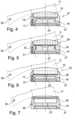
- FIG. 4 A so-called hydrospeed holder 15 is shown, which can be arranged on the spindle adapter 5.
- a lens 10 is arranged in the holder 15.
- the polishing tool 11 is shown only schematically in Fig. 4 shown.
- the lens holder 15 has a base body 16.
- a lens ring 18 is attached to the base body 16 by means of screws 17.
- the lens 10 is held in the lens ring 18 to prevent radial deflection.
- Air or a polishing agent, preferably a polishing fluid, is passed through a bore 22 to press the lens 10 against the polishing tool 11 during the polishing process.
- the lens holder 15 has a recess 27.
- a tool such as a screwdriver, can be inserted into this recess to release the lens holder 15 from the spindle adapter 5, i.e., to overcome the magnetic force.
- An RFID chip 30, shown only schematically, is arranged in the polishing tool 11. Data about the tool and/or data about the polishing processes can be stored in the RFID chip 30.
- Fig. 5 shows a lens holder 29 designed as a membrane holder.
- the lens holder 29 has a base body 30 to which a lens ring 32 is attached by means of screws 31.
- the lens holder 29 has a membrane 33 that rests against the lens 10, which is held against radial deflection by the lens ring 32. Air is guided through a bore 34 so that the membrane 33 rests against the lens 10 and presses it against the polishing tool 11.
- An RFID chip 30, shown only schematically, is arranged in the polishing tool 11. Data about the tool and/or data about the polishing processes can be stored in the RFID chip 30.
- a lens holder 35 is shown, which is designed as a hydrostatic lens holder.
- the lens holder 35 has a base body 36.
- a lens ring 38 is arranged on the base body 36 by means of screws 37, which holds the lens 10 against radial deflection.
- An elastic and porous coating 13 is arranged in the lens holder 35.
- a fluid, preferably a polishing agent, is passed through the bore 22. This polishing agent flows through the elastic and porous coating 13, so that the lens 10 is hydrostatically mounted and is pressed against the polishing tool 11 during the polishing process.
- An RFID chip 30, shown only schematically, is arranged in the polishing tool 11. Data about the tool and/or data about the polishing processes can be stored in the RFID chip 30.
- the lens holders according to the Figs. 4, 5 and 6 each have the recess 27.
- a tool for example a screwdriver, can be inserted into the recess in order to release the base adapter 16 from the spindle adapter 5.
- the base adapters 16, which are in the Figs. 4, 5 and 6 are constructed in such a way that they can be arranged on the spindle adapter 5 by means of the magnets 7.
- the base adapters 16 each carry only a different lens holder 15, 29 or 35.
- the base adapter 16 can also be used, as in Fig. 7
- the dressing tool 39 can be arranged as shown.
- the dressing of the polishing tool can thus be carried out within the device, i.e. the polishing machine.
- the interchangeability of the lens holders 15, 29, and 35 using the workpiece adapter 40 with the dressing tool 39, which is mounted on a base adapter 16, makes changeover phases very short. Furthermore, the quality of the polished lenses is significantly increased because any changeover inaccuracies are completely eliminated.
- the lens holders 15, 29, 35 are detachably and firmly mounted on the base adapter 16. Each lens holder 15, 29, 35 has its own base adapter 16.
- the dressing tool 39 has its own base adapter 16.
- the polishing tool 11 and the grinding tool 44 each have their own tool adapter 40.
- An RFID chip 30, shown only schematically, is arranged in the polishing tool 11. Data about the tool and/or data from the polishing processes can be stored in the RFID chip 30.
- An RFID chip 36 is arranged in the dressing tool 39. Data about the tool and/or data from the dressing processes can be stored in the RFID chip 30.
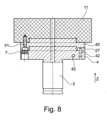
- Fig. 8 shows the polishing tool 11, which is arranged on a tool adapter 40.
- the polishing tool 11 and the tool adapter 40 are detachably connected to one another by means of screws 41.
- the tool adapter 40 is detachably arranged on the spindle adapter 4 of the tool spindle 2.
- the spindle adapter 4 has the permanent magnets 7.
- the recess 27 is arranged in the tool adapter 40 in order to be able to detach the tool adapter 40 from the spindle adapter 4 more easily.
- the spindle adapter 4 has a driving pin 42 so that a rotary movement performed by the spindle adapter 4 is transmitted to the tool adapter 40.
- the magnetic force of the Permanent magnet 7 acts primarily in the Z direction, i.e., in the axial direction of the tool spindle 2.
- the driving pin 42 is provided to transfer the rotational force of the tool spindle 2 to the tool adapter 40.
- the driving pin 42 has a driving function.
- the driving pin 42 engages in the recess 27.
- a separate recess (not shown) can also be provided in the tool adapter 40 for the driving pin 42.
- An RFID chip 45 is arranged in the spindle adapter 4. Data from the polishing tool 11 and/or data from the polishing processes can be stored in the RFID chip 45.
- the RFID chips 30, 36, 45 can be arranged in the tools 11, 39 or the lens holder 15, 29, 35, respectively, or they can be arranged in the adapters 4, 5 of the tools 11, 39 or the lens holder 15, 29, 35.
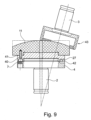
- Fig. 9 are the same parts as in Fig. 8 are provided with the same reference numerals.
- the polishing tool 11 is machined with a grinding tool 43.
- the polishing tool 11 receives its final shape through machining with the grinding tool 43.
- the grinding tool 43 is designed as a cup tool.
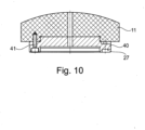
- Fig. 10 The finished polishing tool 11 is shown, which is arranged on the tool adapter 40.
- the same parts are given the same reference numbers as in the Fig. 8 and 9 provided.
- Fig. 11 shows the lens holder 15, which is detachably fixed to the base adapter 16 by means of screws 17.
- the tool adapter 16 is detachably mounted on the spindle adapter 5 by means of the permanent magnets 7.
- the spindle adapter 5 is in turn mounted on the spindle 3.
- the lens holder 15, i.e. the lens ring 18, is mounted according to Fig. 11 machined with a grinding tool 44.
- the lens ring 18 receives its final shape with the grinding tool 44.
- the grinding tool 44 is arranged on the spindle adapter 4, which is shown only schematically.
- the spindle adapter 4 is arranged on the tool spindle 2.
- the grinding tool 44 is designed as a cup tool.
- Fig. 12 shows the processing of a lens 10 with the polishing tool 11.
- the lens 10 is arranged in the lens holder 15, which has the lens ring 18.
- the lens ring 18 is arranged on the base adapter 16 by means of screws 17. This is a detachably fixed connection between the lens holder 15 and the base adapter 16.
- the base adapter 16 is arranged on the spindle adapter 5 by means of magnets 7.
- the spindle adapter 5 is in turn arranged on the workpiece spindle 3.
- An O-ring 9 is provided for sealing between the base adapter 16 and the spindle adapter 5.
- the spindle adapter 5 also has a drive pin 8, which serves to drive the base adapter 16 when the spindle adapter 5 is set in a rotary motion.
- the base adapter 16 is also set in a rotary motion by means of the drive pin 8.
- the polishing tool 11 is removably and firmly attached to the tool adapter 40 by means of screws 41.
- the tool adapter 40 is attached to the spindle adapter 4 by means of magnets 7.
- An O-ring 9 is also provided for sealing.
- the spindle adapter 4 is attached to the tool spindle 2.
- the lens 10 With the system shown, it is possible to polish the lens 10 with the polishing tool 11.
- the tools and lens holders can be easily exchanged using the adapter combinations spindle adapter 4 and tool adapter 40, as well as spindle adapter 5 and base adapter 16. If the polishing tool 11 requires reworking, the lens holder 15 with the base adapter 16 is detached from the spindle adapter 5, and the dressing tool 39 is inserted according to Fig. 7 with the base adapter 16 and the dressing tool 39 arranged on the workpiece spindle 3.
- Each tool or lens holder has its own tool or base adapter.
- the structure of the Fig. 12 Starting from the polishing tool 11 with the tool adapter 40 is released from the spindle adapter 4 and the grinding tool 44 is inserted according to Fig. 11 with the tool adapter 40 arranged on the spindle adapter 4 of the tool spindle 2.
- the spindle adapters 4 and 5 are universal parts.
- the tool adapters 40 and the base adapters 16 are also universal parts. Only the polishing tool 11 and the lens holders 15, 29, and 35 are lens-specific parts. These lens-specific parts are adapted to the various lenses to be processed and manufactured.
- the spindle adapter 4 of the tool spindle 2 can be larger than the spindle adapter 5 of the workpiece spindle 3, since the tool adapters 4 accommodate the tools, such as the polishing tool 11 and the grinding tool 43.
- the base adapter 16 can be smaller than the tool adapter 40, since the base adapter 16 only accommodates the relatively small lens holder 15, 29, 35.
- spindle adapters 4, 5 have the same sizes.
- all parts that are not lens-related namely the spindle adapter 4, the spindle adapter 5, the base adapter 16 and the tool adapter 40, are standardized so that the system can be constructed with few parts.
- the tools for example, the polishing tool 11, are preferably made of plastic. This is preferably a sandable plastic.
- the machining (dressing process) of the polishing tool 11 takes place in the device 1 according to the invention. It is no longer necessary to perform the dressing process of the polishing tool 11 or the lens holder 15 in a separate machine. Furthermore, the third spindle, as known from the prior art, can also be omitted.
- a control device (not shown) is provided in the device 1 according to the invention.
- the lens data is entered into the control device and stored there.
- Software preferably AI-controlled software, suggests which tools should be combined.
- the device 1 according to the invention and the method according to the invention have the advantage that standardized components, such as spindle adapter 4, spindle adapter 5, base adapter 16, or tool adapter 40, can be used.
- a further advantage is that a software-controlled, preferably AI-controlled, user interface is available.
- Another particular advantage is that only a two-spindle machine is required.
- An O-ring 59 is provided for sealing between the base adapter 16 and the lens ring 18.
- Fig. 13 shows the polishing tool 11, which is detachably fixed to the tool adapter 40 by means of screws 41
- the tool adapter 40 is releasably attached to the spindle adapter 4 by means of magnets 7.
- the spindle adapter 4 is arranged on the tool spindle 2.
- the dressing tool 39 is provided for dressing the polishing tool 11.
- the dressing tool 39 is arranged on the tool adapter 16.
- the tool adapter 16 is detachably attached to the spindle adapter 5 by means of magnets 7.
- the spindle adapter 5 is fixedly or detachably connected to the workpiece spindle 3.
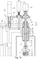
- Fig. 14 shows the tool spindle 2, which can perform an evasive movement in the direction of its longitudinal axis L in the direction of the double arrow A.
- the polishing tool 11 is shown, with which the lens 10 is polished.
- the lens 10 is arranged in the lens ring 18.
- the lens ring 18 is attached to the base adapter 16 by means of a screw 17.
- the polishing tool 11 is attached to a Fig. 14 tool adapter 40, not shown in detail.
- the tool adapter 40 is, as shown in Fig. 12 presented, designed.
- the tool adapter 40 is arranged on the tool spindle 2.
- the tool spindle 2 is designed as a split spindle with an outer spindle 2a and an inner spindle 2b.
- the outer spindle 2a is driven by a motor 56 via a belt 54.
- the outer spindle 2a transmits its rotational movement to the inner spindle 2b via a drive pin 46.
- An elongated hole 60 is provided so that the drive pin 46 can move axially in the direction of arrow A.
- a spring 47 is provided for the spring-loaded mounting.
- the spring 47 exerts a force F2 in the direction of arrow B.
- a pneumatic cylinder 48 exerts a force F1 in the direction of arrow C.
- a stop 49 is provided.
- the stop 49 can be designed as a micrometer stop. This means that the stop limits the maximum stroke movement in the direction of arrow B of the inner spindle 2b. This stop 49 can be adjusted very precisely.
- the driving pin 46 is advantageously arranged in an elongated hole (not shown) so that the inner spindle 2b can move relative to the outer spindle 2a in the direction of arrow A without the driving pin 46 limiting the movement.
- the outer spindle 2a is mounted by means of ball bearings (not shown) arranged in bearing housings 50, 55 so that it can rotate about the longitudinal axis L at a predetermined rotational speed ⁇ .
- the inner spindle 2b has a continuous longitudinal bore 58. Compressed air or a polishing suspension can be passed through the longitudinal bore 58. The compressed air or polishing suspension is fed through a rotary feedthrough 45 into the longitudinal bore 58 of the inner spindle 2b.
- the tool spindle 2 can be operated in two modes.
- the first mode the tool spindle 2 is fixed or rigidly positioned along the longitudinal axis L. This means that the tool spindle 2 cannot deflect in the direction of arrow A during machining of the optical lens 10.
- the pneumatic cylinder 48 is extended in the direction of arrow C, pressing against a holding plate 51 with a force F1.
- the holding plate 51 is mounted for movement in the direction of the double arrow A.
- the pneumatic cylinder 48 for actuating a piston 52 is arranged on a housing part 53 (not shown in detail).
- the holding plate 51 and the housing part 53 are arranged at an equidistant, non-variable distance from one another.
- the tool spindle 2 is fixedly mounted in the direction of the longitudinal axis L of the tool spindle 2. Nevertheless, the tool spindle 2 can rotate about the longitudinal axis L at a rotational speed ⁇ .
- the fixed mounting refers only to the deflection in the direction of the longitudinal axis L of the inner spindle 2b of the tool spindle 2.
- spring 47 acts between the retaining plate 51 and the housing part 53.
- the spring 47 is designed as a compression spring.
- the spring 47 pushes the retaining plate 51 away from the housing part 53 in the direction of arrow B.
- the force F+ is switched to a force F-.
- F- This means that the spring force F- is in a floating state with the spring force FF of the spring 47.
- the spring 47 pushes the retaining plate 51 away from the housing part 53 with the spring force FF.
- the force F- acting in the opposite direction pulls in the opposite direction. This creates the floating force.
- F- - (spring force FF of spring 47) ⁇ -force.
- This ⁇ force is balanced so that the inner tool spindle 2b is moved in the outer tool spindle 2a (weight- and friction-relieved) in the opposite direction to the spring force FF by a predetermined stroke. This then represents the working force for polishing or another work process.
- the inner spindle 2b of the tool spindle 2 is spring-mounted.
- the device 1 has a plurality of O-rings 57 for sealing.
Landscapes
- Engineering & Computer Science (AREA)
- Mechanical Engineering (AREA)
- Grinding And Polishing Of Tertiary Curved Surfaces And Surfaces With Complex Shapes (AREA)
Priority Applications (1)
| Application Number | Priority Date | Filing Date | Title |
|---|---|---|---|
| EP23211964.4A EP4559622A1 (fr) | 2023-11-24 | 2023-11-24 | Dispositif de polissage de surfaces sphériques de lentilles et procédé de polissage de surfaces sphériques de lentilles |
Applications Claiming Priority (1)
| Application Number | Priority Date | Filing Date | Title |
|---|---|---|---|
| EP23211964.4A EP4559622A1 (fr) | 2023-11-24 | 2023-11-24 | Dispositif de polissage de surfaces sphériques de lentilles et procédé de polissage de surfaces sphériques de lentilles |
Publications (1)
| Publication Number | Publication Date |
|---|---|
| EP4559622A1 true EP4559622A1 (fr) | 2025-05-28 |
Family
ID=88969807
Family Applications (1)
| Application Number | Title | Priority Date | Filing Date |
|---|---|---|---|
| EP23211964.4A Pending EP4559622A1 (fr) | 2023-11-24 | 2023-11-24 | Dispositif de polissage de surfaces sphériques de lentilles et procédé de polissage de surfaces sphériques de lentilles |
Country Status (1)
| Country | Link |
|---|---|
| EP (1) | EP4559622A1 (fr) |
Citations (6)
| Publication number | Priority date | Publication date | Assignee | Title |
|---|---|---|---|---|
| US2955390A (en) * | 1956-07-20 | 1960-10-11 | Edwin D Philips | Lens grinding machine or generator |
| EP0685298A1 (fr) * | 1994-04-12 | 1995-12-06 | Schneider GmbH + Co. KG | Procédé et dispositif pour fabriquer des lentilles asphériques |
| EP0727280A1 (fr) | 1995-02-14 | 1996-08-21 | Opto Tech GmbH | Procédé et appareil pour polir des lentilles sphériques |
| EP0807491A1 (fr) * | 1996-05-17 | 1997-11-19 | Opto Tech GmbH | Support pour lentille optique et procédé pour polir des lentilles |
| DE19737215A1 (de) * | 1997-08-27 | 1999-03-04 | Schneider Gmbh & Co Kg | Werkzeugkomibation bestehend aus Spannwerkzeug für Linsen und Abrichtwerkzeug für Polierwerkzeuge |
| DE102020128088B3 (de) * | 2020-10-26 | 2022-04-14 | Optotech Optikmaschinen Gmbh | Verfahren zum Feinschleifen oder Polieren einer optischen Linse auf einem Werkstückträger |
-
2023
- 2023-11-24 EP EP23211964.4A patent/EP4559622A1/fr active Pending
Patent Citations (6)
| Publication number | Priority date | Publication date | Assignee | Title |
|---|---|---|---|---|
| US2955390A (en) * | 1956-07-20 | 1960-10-11 | Edwin D Philips | Lens grinding machine or generator |
| EP0685298A1 (fr) * | 1994-04-12 | 1995-12-06 | Schneider GmbH + Co. KG | Procédé et dispositif pour fabriquer des lentilles asphériques |
| EP0727280A1 (fr) | 1995-02-14 | 1996-08-21 | Opto Tech GmbH | Procédé et appareil pour polir des lentilles sphériques |
| EP0807491A1 (fr) * | 1996-05-17 | 1997-11-19 | Opto Tech GmbH | Support pour lentille optique et procédé pour polir des lentilles |
| DE19737215A1 (de) * | 1997-08-27 | 1999-03-04 | Schneider Gmbh & Co Kg | Werkzeugkomibation bestehend aus Spannwerkzeug für Linsen und Abrichtwerkzeug für Polierwerkzeuge |
| DE102020128088B3 (de) * | 2020-10-26 | 2022-04-14 | Optotech Optikmaschinen Gmbh | Verfahren zum Feinschleifen oder Polieren einer optischen Linse auf einem Werkstückträger |
Similar Documents
| Publication | Publication Date | Title |
|---|---|---|
| EP2338640B1 (fr) | Machine de meulage de pièces optiques, en particuliere de verres à lunettes en plastique | |
| EP0807491A1 (fr) | Support pour lentille optique et procédé pour polir des lentilles | |
| DE102016004328A1 (de) | Werkzeugspindel für eine Vorrichtung zur Feinbearbeitung von optisch wirksamen Flächen an Werkstücken | |
| EP0483064A1 (fr) | Centre d'usinage pour le meulage de pièces ayant des surfaces de forme complexe | |
| DE3927412A1 (de) | Linsenschleifvorrichtung und verfahren zum schleifen von linsen | |
| DE102018126260B4 (de) | Maschine und Verfahren zum Schleifen dünnwandiger Werkstücke | |
| DE102009040062A1 (de) | Vorrichtung zur Endbearbeitung ringförmiger Werkstücke, insbesondere von Lagerringen | |
| DE1752510C3 (de) | Vorrichtung zum zentrischen Aufspannen eines ringförmigen Werkstückes an einer Planscheibe | |
| DE102016112999A1 (de) | Werkstückaufnahme für Linsenbearbeitungsmaschine, Linsenbearbeitungsmaschine und Verfahren zur Bearbeitung einer optischen Linse | |
| EP2188087B1 (fr) | Machine-outil avec outil de rodage | |
| EP0260692B1 (fr) | Machine-outil avec un porte-broche à forer et à fraiser à déplacement dans la direction Z sur un châssis de machine | |
| EP0727280B1 (fr) | Appareil pour polir des lentilles sphériques | |
| EP0159383B1 (fr) | Machine pour meuler les surfaces toriques de lentilles optiques | |
| EP4446054B1 (fr) | Dispositif de polissage de lentille optique ou de miroir optique et procédé de polissage de lentille optique ou de miroir optique | |
| EP4559622A1 (fr) | Dispositif de polissage de surfaces sphériques de lentilles et procédé de polissage de surfaces sphériques de lentilles | |
| EP3250341B1 (fr) | Procédé, en particulier de fabrication flexible plus efficace de modèles d'usinage au moyen de plusieurs axes | |
| DE19738818B4 (de) | Verfahren und Vorrichtung zur formgeregelten Feinstbearbeitung eines Werkstücks | |
| DE188491C (de) | Verfahren und Vorrichtung zum Schleifen von Kugelflächen mittels hohler nur mit einer ringförmigen Randfläche schleifender Werkzeuge | |
| WO2012069168A2 (fr) | Dispositif et procédé pour usiner une lentille optique | |
| DE102009059991B3 (de) | Vorrichtung zur Feinstbearbeitung von Werkstücken, insbesondere von ringförmigen Werkstücken | |
| DE19801377C2 (de) | Schleifscheibe mit Umfangsrille | |
| DE3751988T2 (de) | Schalttellermaschine mit elektrischer Steuerung | |
| DE19737215A1 (de) | Werkzeugkomibation bestehend aus Spannwerkzeug für Linsen und Abrichtwerkzeug für Polierwerkzeuge | |
| DE10057228B4 (de) | Verfahren zum Schleifen von optischen Linsen mittels Ring- und Formwerkzeugen und Vorrichtung zur Durchführung des Verfahrens | |
| DE19543184A1 (de) | Vorrichtung zum Polieren von kegelförmigen Werkstückoberflächen |
Legal Events
| Date | Code | Title | Description |
|---|---|---|---|
| PUAI | Public reference made under article 153(3) epc to a published international application that has entered the european phase |
Free format text: ORIGINAL CODE: 0009012 |
|
| STAA | Information on the status of an ep patent application or granted ep patent |
Free format text: STATUS: REQUEST FOR EXAMINATION WAS MADE |
|
| 17P | Request for examination filed |
Effective date: 20240603 |
|
| AK | Designated contracting states |
Kind code of ref document: A1 Designated state(s): AL AT BE BG CH CY CZ DE DK EE ES FI FR GB GR HR HU IE IS IT LI LT LU LV MC ME MK MT NL NO PL PT RO RS SE SI SK SM TR |