EP4550765A1 - Faltbare elektronische vorrichtung und scharnier - Google Patents
Faltbare elektronische vorrichtung und scharnier Download PDFInfo
- Publication number
- EP4550765A1 EP4550765A1 EP23905611.2A EP23905611A EP4550765A1 EP 4550765 A1 EP4550765 A1 EP 4550765A1 EP 23905611 A EP23905611 A EP 23905611A EP 4550765 A1 EP4550765 A1 EP 4550765A1
- Authority
- EP
- European Patent Office
- Prior art keywords
- rotating member
- arc
- foldable
- support surface
- assembly
- Prior art date
- Legal status (The legal status is an assumption and is not a legal conclusion. Google has not performed a legal analysis and makes no representation as to the accuracy of the status listed.)
- Pending
Links
Images


Classifications
-
- G—PHYSICS
- G06—COMPUTING OR CALCULATING; COUNTING
- G06F—ELECTRIC DIGITAL DATA PROCESSING
- G06F1/00—Details not covered by groups G06F3/00 - G06F13/00 and G06F21/00
- G06F1/16—Constructional details or arrangements
-
- H—ELECTRICITY
- H04—ELECTRIC COMMUNICATION TECHNIQUE
- H04M—TELEPHONIC COMMUNICATION
- H04M1/00—Substation equipment, e.g. for use by subscribers
- H04M1/02—Constructional features of telephone sets
- H04M1/0202—Portable telephone sets, e.g. cordless phones, mobile phones or bar type handsets
- H04M1/0206—Portable telephones comprising a plurality of mechanically joined movable body parts, e.g. hinged housings
- H04M1/0208—Portable telephones comprising a plurality of mechanically joined movable body parts, e.g. hinged housings characterized by the relative motions of the body parts
- H04M1/0214—Foldable telephones, i.e. with body parts pivoting to an open position around an axis parallel to the plane they define in closed position
-
- F—MECHANICAL ENGINEERING; LIGHTING; HEATING; WEAPONS; BLASTING
- F16—ENGINEERING ELEMENTS AND UNITS; GENERAL MEASURES FOR PRODUCING AND MAINTAINING EFFECTIVE FUNCTIONING OF MACHINES OR INSTALLATIONS; THERMAL INSULATION IN GENERAL
- F16C—SHAFTS; FLEXIBLE SHAFTS; ELEMENTS OR CRANKSHAFT MECHANISMS; ROTARY BODIES OTHER THAN GEARING ELEMENTS; BEARINGS
- F16C11/00—Pivots; Pivotal connections
- F16C11/04—Pivotal connections
- F16C11/10—Arrangements for locking
- F16C11/103—Arrangements for locking frictionally clamped
-
- F—MECHANICAL ENGINEERING; LIGHTING; HEATING; WEAPONS; BLASTING
- F16—ENGINEERING ELEMENTS AND UNITS; GENERAL MEASURES FOR PRODUCING AND MAINTAINING EFFECTIVE FUNCTIONING OF MACHINES OR INSTALLATIONS; THERMAL INSULATION IN GENERAL
- F16C—SHAFTS; FLEXIBLE SHAFTS; ELEMENTS OR CRANKSHAFT MECHANISMS; ROTARY BODIES OTHER THAN GEARING ELEMENTS; BEARINGS
- F16C11/00—Pivots; Pivotal connections
- F16C11/04—Pivotal connections
- F16C11/12—Pivotal connections incorporating flexible connections, e.g. leaf springs
-
- G—PHYSICS
- G06—COMPUTING OR CALCULATING; COUNTING
- G06F—ELECTRIC DIGITAL DATA PROCESSING
- G06F1/00—Details not covered by groups G06F3/00 - G06F13/00 and G06F21/00
- G06F1/16—Constructional details or arrangements
- G06F1/1613—Constructional details or arrangements for portable computers
- G06F1/1615—Constructional details or arrangements for portable computers with several enclosures having relative motions, each enclosure supporting at least one I/O or computing function
- G06F1/1616—Constructional details or arrangements for portable computers with several enclosures having relative motions, each enclosure supporting at least one I/O or computing function with folding flat displays, e.g. laptop computers or notebooks having a clamshell configuration, with body parts pivoting to an open position around an axis parallel to the plane they define in closed position
-
- G—PHYSICS
- G06—COMPUTING OR CALCULATING; COUNTING
- G06F—ELECTRIC DIGITAL DATA PROCESSING
- G06F1/00—Details not covered by groups G06F3/00 - G06F13/00 and G06F21/00
- G06F1/16—Constructional details or arrangements
- G06F1/1613—Constructional details or arrangements for portable computers
- G06F1/1633—Constructional details or arrangements of portable computers not specific to the type of enclosures covered by groups G06F1/1615 - G06F1/1626
- G06F1/1637—Details related to the display arrangement, including those related to the mounting of the display in the housing
- G06F1/1641—Details related to the display arrangement, including those related to the mounting of the display in the housing the display being formed by a plurality of foldable display components
-
- G—PHYSICS
- G06—COMPUTING OR CALCULATING; COUNTING
- G06F—ELECTRIC DIGITAL DATA PROCESSING
- G06F1/00—Details not covered by groups G06F3/00 - G06F13/00 and G06F21/00
- G06F1/16—Constructional details or arrangements
- G06F1/1613—Constructional details or arrangements for portable computers
- G06F1/1633—Constructional details or arrangements of portable computers not specific to the type of enclosures covered by groups G06F1/1615 - G06F1/1626
- G06F1/1637—Details related to the display arrangement, including those related to the mounting of the display in the housing
- G06F1/1652—Details related to the display arrangement, including those related to the mounting of the display in the housing the display being flexible, e.g. mimicking a sheet of paper, or rollable
-
- G—PHYSICS
- G06—COMPUTING OR CALCULATING; COUNTING
- G06F—ELECTRIC DIGITAL DATA PROCESSING
- G06F1/00—Details not covered by groups G06F3/00 - G06F13/00 and G06F21/00
- G06F1/16—Constructional details or arrangements
- G06F1/1613—Constructional details or arrangements for portable computers
- G06F1/1633—Constructional details or arrangements of portable computers not specific to the type of enclosures covered by groups G06F1/1615 - G06F1/1626
- G06F1/1675—Miscellaneous details related to the relative movement between the different enclosures or enclosure parts
- G06F1/1681—Details related solely to hinges
-
- G—PHYSICS
- G09—EDUCATION; CRYPTOGRAPHY; DISPLAY; ADVERTISING; SEALS
- G09F—DISPLAYING; ADVERTISING; SIGNS; LABELS OR NAME-PLATES; SEALS
- G09F9/00—Indicating arrangements for variable information in which the information is built-up on a support by selection or combination of individual elements
- G09F9/30—Indicating arrangements for variable information in which the information is built-up on a support by selection or combination of individual elements in which the desired character or characters are formed by combining individual elements
- G09F9/301—Indicating arrangements for variable information in which the information is built-up on a support by selection or combination of individual elements in which the desired character or characters are formed by combining individual elements flexible foldable or roll-able electronic displays, e.g. thin LCD, OLED
-
- H—ELECTRICITY
- H04—ELECTRIC COMMUNICATION TECHNIQUE
- H04M—TELEPHONIC COMMUNICATION
- H04M1/00—Substation equipment, e.g. for use by subscribers
- H04M1/02—Constructional features of telephone sets
- H04M1/0202—Portable telephone sets, e.g. cordless phones, mobile phones or bar type handsets
- H04M1/0206—Portable telephones comprising a plurality of mechanically joined movable body parts, e.g. hinged housings
- H04M1/0208—Portable telephones comprising a plurality of mechanically joined movable body parts, e.g. hinged housings characterized by the relative motions of the body parts
- H04M1/0214—Foldable telephones, i.e. with body parts pivoting to an open position around an axis parallel to the plane they define in closed position
- H04M1/0216—Foldable in one direction, i.e. using a one degree of freedom hinge
- H04M1/022—The hinge comprising two parallel pivoting axes
-
- H—ELECTRICITY
- H04—ELECTRIC COMMUNICATION TECHNIQUE
- H04M—TELEPHONIC COMMUNICATION
- H04M1/00—Substation equipment, e.g. for use by subscribers
- H04M1/02—Constructional features of telephone sets
- H04M1/0202—Portable telephone sets, e.g. cordless phones, mobile phones or bar type handsets
- H04M1/026—Details of the structure or mounting of specific components
- H04M1/0266—Details of the structure or mounting of specific components for a display module assembly
- H04M1/0268—Details of the structure or mounting of specific components for a display module assembly including a flexible display panel
-
- H—ELECTRICITY
- H05—ELECTRIC TECHNIQUES NOT OTHERWISE PROVIDED FOR
- H05K—PRINTED CIRCUITS; CASINGS OR CONSTRUCTIONAL DETAILS OF ELECTRIC APPARATUS; MANUFACTURE OF ASSEMBLAGES OF ELECTRICAL COMPONENTS
- H05K5/00—Casings, cabinets or drawers for electric apparatus
- H05K5/02—Details
- H05K5/0217—Mechanical details of casings
- H05K5/0226—Hinges
Definitions
- This application relates to the field of electronic device technologies, and in particular, to a foldable electronic device and a hinge.
- a foldable display is widely used in a foldable electronic device.
- the foldable display is mainly implemented by combining a flexible display (organic light-emitting diode, OLED) and a hinge.
- OLED organic light-emitting diode
- the flexible display is a fragile component, large pressure or a large pulling force cannot be borne in a folding process. Otherwise, a bump, a crease, breakage, or the like may occur.
- some manufacturers start to use a hinge with an adjustable length to prevent the flexible display from being squeezed in a folding process.
- an existing hinge has a complex structure, uses more parts, and has high manufacturing costs. In an assembling process, a complex assembly process, low assembly efficiency, and other problems also occur.
- This application provides a foldable electronic device and a hinge that are simple in structure and can well support a flexible display.
- this application provides a foldable electronic device, including a first housing, a second housing, a flexible display, and a hinge.
- the hinge includes a main shaft, and a first foldable assembly and a second foldable assembly that are symmetrically disposed with respect to the main shaft.
- the first foldable assembly and the second foldable assembly may rotate toward or away from each other, to implement a folding function of the hinge.
- the first foldable assembly includes a first rotating member, a first body, and a first connecting rod. A first end of the first rotating member is rotatably connected to the main shaft, and a second end of the first rotating member is slidably connected to the first body.
- the second foldable assembly includes a second rotating member, a second body, and a second connecting rod.
- a first end of the second rotating member is rotatably connected to the main shaft, and a second end of the second rotating member is slidably connected to the second body.
- a first end of the first connecting rod is rotatably connected to the first body, and a second end of the first connecting rod is rotatably connected to the first end of the second rotating member.
- a first end of the second connecting rod is rotatably connected to the second body, and a second end of the second connecting rod is rotatably connected to the first end of the first rotating member.
- the first housing is fastened to the first body, and the second housing is fastened to the second body.
- a first part of the flexible display is fastened to the first housing, and a second part of the flexible display is fastened to the second housing.
- the first body has a first support surface for supporting the flexible display
- the second body has a second support surface for supporting the flexible display.
- the first housing has a first mounting surface
- the second housing has a second mounting surface
- a side that is of the flexible display and that is opposite to the display surface is fastened to the first mounting surface and the second mounting surface.
- the first mounting surface, the second mounting surface, the first support surface, and the second support surface can provide good planar support for the flexible display.
- the first mounting surface, the second mounting surface, the first support surface, and the second support surface can effectively support the flexible display, so as to effectively prevent deformation of the flexible display, and effectively ensure use security of the flexible display and user experience.
- a case in which a support effect for the flexible display is reduced as there is an obvious gap between the first mounting surface and the first support surface can be effectively avoided.
- an action force may be applied to the first housing and the second housing, so that the first housing and the second housing rotate relative to each other.
- the first housing may drive the first rotating member to move via the first body
- the second housing may drive the second rotating member to move via the second body, to implement a foldable connection between the first housing and the second housing.
- a connection length among the first housing, the hinge, and the second housing is extended or shortened, so that no extrusion pressure or stretching force is caused to the flexible display, and warpage, a crease, breakage, or the like of the flexible display can be avoided.
- the main shaft may have a third support surface.
- the first mounting surface, the first support surface, the third support surface, the second support surface, and the second mounting surface are sequentially spliced to form a support surface for supporting the flexible display. That is, the first mounting surface, the second mounting surface, the first support surface, the second support surface, and the third support surface all can provide good planar support for the flexible display, so that use security of the flexible display and user experience can be effectively ensured.
- the flexible display may be fastened on the third support surface, to implement fastening between the flexible display and the third support surface.
- the flexible display may be lapped on the third support surface, that is, the flexible display and the third support surface may not in a fastening relationship.
- the third support surface may be a flat surface, or may be a protruding arc-shaped surface, or a surface that is partially a flat surface and partially a curved surface.
- a side that is of the third support surface and that is adjacent to the first support surface is a first curved surface
- a side that is of the third support surface and that is adjacent to the second support surface is a second curved surface
- a flat surface is disposed between the first curved surface and the second curved surface.
- the first rotating member and the first connecting rod in the first foldable assembly may be both located on a side that is of the first body and that is opposite to the first support surface, to avoid a case in which a support effect of the first support surface on the flexible display is affected as the first rotating member and the first connecting rod protrude from the first support surface.
- the second rotating member and the second connecting rod in the second foldable assembly may be both located on a side that is of the second body and that is opposite to the second support surface, to avoid a case in which a support effect of the second support surface on the flexible display is affected as the second rotating member and the second connecting rod protrude from the second support surface.
- the second end of the first connecting rod has a first pin hole
- the first end of the second rotating member has a second pin hole
- the first connecting rod is rotatably connected to the second rotating member via a pin shaft that penetrates the first pin hole and the second pin hole.
- the second end of the second connecting rod has a third pin hole
- the first end of the first rotating member has a fourth pin hole
- the second connecting rod is rotatably connected to the first rotating member via a pin shaft that penetrates the third pin hole and the fourth pin hole.
- the hinge when the hinge changes from an unfolded state to a folded state, the first foldable assembly and the second foldable assembly rotate toward each other, the first rotating member and the first body rotate synchronously, and the second rotating member and the second body rotate synchronously.
- the first rotating member drives the first connecting rod to move
- the first connecting rod drives the second body to approach the main shaft
- the second rotating member drives the second connecting rod to move
- the second connecting rod drives the first body to approach the main shaft.
- the first foldable assembly and the second foldable assembly rotate away from each other, the first rotating member and the first body rotate synchronously, and the second rotating member and the second body rotate synchronously.
- the first rotating member drives the first connecting rod to move
- the first connecting rod drives the second body to be away from the main shaft
- the second rotating member drives the second connecting rod to move
- the second connecting rod drives the first body to be away from the main shaft.
- the foldable electronic device is in an outward-foldable form, and when the foldable electronic device is folded, the flexible display is located outside.
- a folding function of the hinge may be implemented via the main shaft, the first rotating member, the first body, the first connecting rod, the second rotating member, the second body, and the second connecting rod.
- the length of the hinge may further change, to avoid an action force of stretching or compressing the flexible display.
- the hinge uses a small quantity of parts, and has a simple structure, so that manufacturing costs and assembling costs of the hinge can be effectively reduced.
- the main shaft may include a first shaft body and a second shaft body.
- the first shaft body has a convex first cylindrical surface
- the second shaft body has a concave second cylindrical surface.
- the first cylindrical surface and the second cylindrical surface are disposed opposite to each other, so that the first shaft body and the second shaft body enclose first arc-shaped space.
- the first end of the first rotating member has a first arc-shaped arm, and the first arc-shaped arm is located in the first arc-shaped space between the first cylindrical surface and the second cylindrical surface. That is, the first end of the first rotating member is rotatably connected to the main shaft through the first arc-shaped arm and the first arc-shaped space.
- the first shaft body may further have a convex third cylindrical surface
- the second shaft body has a concave fourth cylindrical surface.
- the third cylindrical surface and the fourth cylindrical surface are disposed opposite to each other, so that the first shaft body and the second shaft body enclose second arc-shaped space.
- the first end of the second rotating member has a second arc-shaped arm, and the second arc-shaped arm is located in the second arc-shaped space between the third cylindrical surface and the fourth cylindrical surface. That is, the first end of the second rotating member is rotatably connected to the main shaft through the second arc-shaped arm and the second arc-shaped space.
- the first arc-shaped arm rotates along the first arc-shaped space
- the second arc-shaped arm rotates along the second arc-shaped space
- the first arc-shaped arm rotates out of the first arc-shaped space
- the second arc-shaped arm rotates out of the second arc-shaped space.
- the first arc-shaped arm rotates into the first arc-shaped space
- the second arc-shaped arm rotates into the second arc-shaped space.
- the main shaft may include a first shaft body and a second shaft body.
- the first shaft body and the second shaft body can be separately manufactured, so that manufacturing time can be shortened.
- the first arc-shaped arm of the first rotating member may be disposed between the first cylindrical surface and the second cylindrical surface, and then the first shaft body and the second shaft body are fastened via a fastener like a screw, to implement assembling among the first rotating member, the second rotating member, the first shaft body, and the second shaft body.
- a surface that is of the first shaft body and that is away from the third cylindrical surface may be a flat surface. This helps implement flat disposition of the hinge.
- the first body may have a first sliding groove
- the first rotating member may have a first sliding end
- the first sliding end may be slidably disposed in the first sliding groove, to implement a slidable connection between the first body and the first rotating member.
- the second body may have a second sliding groove
- the second rotating member may have a second sliding end
- the second sliding end may be slidably disposed in the second sliding groove, to implement a slidable connection between the second body and the second rotating member.
- the first sliding end slides into the first sliding groove, and the second sliding end slides into the second sliding groove.
- the first sliding end slides out of the first sliding groove, and the second sliding end slides out of the second sliding groove.
- the first foldable assembly may further include a first suspension assembly.
- the first rotating member may have a first mounting groove, and the first suspension assembly is disposed in the first mounting groove; and the first suspension assembly is in sliding contact with the first body, and is configured to provide a damping force when the first rotating member slides relative to the first body.
- the first mounting groove configured to accommodate the first suspension assembly is provided in the first rotating member, so that compactness of the first foldable assembly can be improved, and a miniaturization design of the hinge can be implemented.
- the second foldable assembly may further include a second suspension assembly.
- the second rotating member may have a second mounting groove, and the second suspension assembly is disposed in the second mounting groove; and the second suspension assembly is in sliding contact with the second body, and is configured to provide a damping force when the second rotating member slides relative to the second body.
- the second mounting groove configured to accommodate the second suspension assembly is provided in the second rotating member, so that compactness of the second foldable assembly can be improved, and a miniaturization design of the hinge can be implemented.
- the first suspension assembly or the second suspension assembly may be omitted, so that a quantity of used parts of the hinge can be reduced, and a suspension function can be implemented via the first suspension assembly or the second suspension assembly.
- the foldable electronic device may further include a cover assembly, and the cover assembly includes a first plate body, a second plate body, and a third plate body.
- the first plate body is fastened to the first rotating member
- the second plate body is fastened to the second rotating member
- the third plate body is fastened to the main shaft.
- the cover assembly can be disposed to effectively shield and protect a part like the first rotating member, the second rotating member, the first suspension assembly, or the second suspension assembly in the hinge for effectively shielding an external foreign matter. This can improve use safety of the hinge.
- the hinge may further include a synchronization assembly, where the synchronization assembly is in transmission connection to the first body, the main shaft, and the second body for the first foldable assembly and the second foldable assembly to synchronously and reversely rotate.
- the synchronization assembly may include a first synchronization member and a second synchronization member.
- the first synchronization member is rotatably connected to the main shaft, and a rotation axis center of the first synchronization member coincides with a rotation axis center of the first rotating member; and the second synchronization member is rotatably connected to the main shaft, and a rotation axis center of the second synchronization member coincides with a rotation axis center of the second rotating member.
- the first synchronization member has a first tooth-shaped part and a first sliding part
- the second synchronization member has a second tooth-shaped part and a second sliding part. The first tooth-shaped part is engaged with the second tooth-shaped part, the first sliding part is slidably connected to the first body, and the second sliding part is slidably connected to the second body.
- the synchronization assembly can be disposed to ensure smoothness of the first foldable assembly and the second foldable assembly during relative movement, so that use experience and reliability of the hinge can be improved.
- the hinge may include a first foldable assembly and a second foldable assembly that are correspondingly disposed.
- a plurality of first foldable assemblies and a plurality of second foldable assemblies that are disposed in a one-to-one correspondence may be included, to improve force-bearing performance of the hinge.
- first foldable assemblies and second foldable assemblies When the hinge includes a plurality of first foldable assemblies and a plurality of second foldable assemblies, the plurality of first foldable assemblies and the plurality of second foldable assemblies are disposed in a direction parallel to a length direction (an axial direction) of the main shaft.
- quantities of first foldable assemblies and second foldable assemblies may be properly set based on an actual requirement. This is not limited in this application.
- this application further provides a hinge, which may be used in a foldable electronic device having a flexible display.
- the hinge may include a main shaft, and a first foldable assembly and a second foldable assembly that are symmetrically disposed with respect to the main shaft.
- the first foldable assembly and the second foldable assembly may rotate toward or away from each other, to implement a folding function of the hinge.
- the first foldable assembly includes a first rotating member, a first body, and a first connecting rod. A first end of the first rotating member is rotatably connected to the main shaft, and a second end of the first rotating member is slidably connected to the first body.
- the second foldable assembly includes a second rotating member, a second body, and a second connecting rod.
- a first end of the second rotating member is rotatably connected to the main shaft, and a second end of the second rotating member is slidably connected to the second body.
- a first end of the first connecting rod is rotatably connected to the first body, and a second end of the first connecting rod is rotatably connected to the first end of the second rotating member.
- a first end of the second connecting rod is rotatably connected to the second body, and a second end of the second connecting rod is rotatably connected to the first end of the first rotating member.
- the first body has a first support surface for supporting the flexible display
- the second body has a second support surface for supporting the flexible display
- the first support surface and the second support surface are located on a same plane.
- the first support surface and the second support surface can provide good planar support.
- the main shaft may have a third support surface for supporting the flexible display.
- the first support surface, the third support surface, and the second support surface are sequentially spliced to form a support surface for supporting the flexible display. That is, the first mounting surface, the second mounting surface, the first support surface, the second support surface, and the third support surface all can provide good planar support for the flexible display, so that use security of the flexible display and user experience can be effectively ensured.
- the flexible display may be fastened on the third support surface, to implement fastening between the flexible display and the third support surface.
- the flexible display may be lapped on the third support surface, that is, the flexible display and the third support surface may not in a fastening relationship.
- the third support surface may be a flat surface, or may be a protruding arc-shaped surface, or a surface that is partially a flat surface and partially a curved surface.
- a side that is of the third support surface and that is adjacent to the first support surface is a first curved surface
- a side that is of the third support surface and that is adjacent to the second support surface is a second curved surface
- a flat surface is disposed between the first curved surface and the second curved surface.
- the first rotating member and the first connecting rod in the first foldable assembly may be both located on a side that is of the first body and that is opposite to the first support surface, to avoid a case in which a support effect of the first support surface on the flexible display is affected as the first rotating member and the first connecting rod protrude from the first support surface.
- the second rotating member and the second connecting rod in the second foldable assembly may be both located on a side that is of the second body and that is opposite to the second support surface, to avoid a case in which a support effect of the second support surface on the flexible display is affected as the second rotating member and the second connecting rod protrude from the second support surface.
- the second end of the first connecting rod has a first pin hole
- the first end of the second rotating member has a second pin hole
- the first connecting rod is rotatably connected to the second rotating member via a pin shaft that penetrates the first pin hole and the second pin hole.
- the second end of the second connecting rod has a third pin hole
- the first end of the first rotating member has a fourth pin hole
- the second connecting rod is rotatably connected to the first rotating member via a pin shaft that penetrates the third pin hole and the fourth pin hole.
- the hinge when the hinge changes from an unfolded state to a folded state, the first foldable assembly and the second foldable assembly rotate toward each other, the first rotating member and the first body rotate synchronously, and the second rotating member and the second body rotate synchronously.
- the first rotating member drives the first connecting rod to move
- the first connecting rod drives the second body to approach the main shaft
- the second rotating member drives the second connecting rod to move
- the second connecting rod drives the first body to approach the main shaft.
- the first foldable assembly and the second foldable assembly rotate away from each other, the first rotating member and the first body rotate synchronously, and the second rotating member and the second body rotate synchronously.
- the first rotating member drives the first connecting rod to move, the first connecting rod drives the second body to be away from the main shaft, the second rotating member drives the second connecting rod to move, and the second connecting rod drives the first body to be away from the main shaft. This can increase a length of the hinge.
- a folding function of the hinge may be implemented via the main shaft, the first rotating member, the first body, the first connecting rod, the second rotating member, the second body, and the second connecting rod.
- the length of the hinge may further change, to avoid an action force of stretching or compressing the flexible display.
- the hinge uses a small quantity of parts, and has a simple structure, so that manufacturing costs and assembling costs of the hinge can be effectively reduced.
- the main shaft may include a first shaft body and a second shaft body.
- the first shaft body has a convex first cylindrical surface
- the second shaft body has a concave second cylindrical surface.
- the first cylindrical surface and the second cylindrical surface are disposed opposite to each other, so that the first shaft body and the second shaft body enclose first arc-shaped space.
- the first end of the first rotating member has a first arc-shaped arm, and the first arc-shaped arm is located in the first arc-shaped space between the first cylindrical surface and the second cylindrical surface. That is, the first end of the first rotating member is rotatably connected to the main shaft through the first arc-shaped arm and the first arc-shaped space.
- the first shaft body may further have a convex third cylindrical surface
- the second shaft body has a concave fourth cylindrical surface.
- the third cylindrical surface and the fourth cylindrical surface are disposed opposite to each other, so that the first shaft body and the second shaft body enclose second arc-shaped space.
- the first end of the second rotating member has a second arc-shaped arm, and the second arc-shaped arm is located in the second arc-shaped space between the third cylindrical surface and the fourth cylindrical surface. That is, the first end of the second rotating member is rotatably connected to the main shaft through the second arc-shaped arm and the second arc-shaped space.
- the first arc-shaped arm rotates along the first arc-shaped space
- the second arc-shaped arm rotates along the second arc-shaped space
- the first arc-shaped arm rotates out of the first arc-shaped space
- the second arc-shaped arm rotates out of the second arc-shaped space.
- the first arc-shaped arm rotates into the first arc-shaped space
- the second arc-shaped arm rotates into the second arc-shaped space.
- the main shaft may include a first shaft body and a second shaft body.
- the first shaft body and the second shaft body can be separately manufactured, so that manufacturing time can be shortened.
- the first arc-shaped arm of the first rotating member may be disposed between the first cylindrical surface and the second cylindrical surface, and then the first shaft body and the second shaft body are fastened via a fastener like a screw, to implement assembling among the first rotating member, the second rotating member, the first shaft body, and the second shaft body.
- a surface that is of the first shaft body and that is away from the first cylindrical surface may be a flat surface. This helps implement flat disposition of the hinge.
- a surface that is of the first shaft body and that is away from the third cylindrical surface may be a flat surface. This helps implement flat disposition of the hinge.
- a back side of the flexible display in the foldable electronic device may be attached to the foregoing two surfaces. That is, the two surfaces can provide a good bearing effect for the flexible display. In addition, because the two surfaces are flat surfaces, flatness of flexible display can be ensured.
- the first body may have a first sliding groove
- the first rotating member may have a first sliding end
- the first sliding end may be slidably disposed in the first sliding groove, to implement a slidable connection between the first body and the first rotating member.
- the second body may have a second sliding groove
- the second rotating member may have a second sliding end
- the second sliding end may be slidably disposed in the second sliding groove, to implement a slidable connection between the second body and the second rotating member.
- the first sliding end slides into the first sliding groove, and the second sliding end slides into the second sliding groove.
- the first sliding end slides out of the first sliding groove, and the second sliding end slides out of the second sliding groove.
- the first foldable assembly may further include a first suspension assembly.
- the first rotating member may have a first mounting groove, and the first suspension assembly is disposed in the first mounting groove; and the first suspension assembly is in sliding contact with the first body, and is configured to provide a damping force when the first rotating member slides relative to the first body.
- the first mounting groove configured to accommodate the first suspension assembly is provided in the first rotating member, so that compactness of the first foldable assembly can be improved, and a miniaturization design of the hinge can be implemented.
- the second foldable assembly may further include a second suspension assembly.
- the second rotating member may have a second mounting groove, and the second suspension assembly is disposed in the second mounting groove; and the second suspension assembly is in sliding contact with the second body, and is configured to provide a damping force when the second rotating member slides relative to the second body.
- the second mounting groove configured to accommodate the second suspension assembly is provided in the second rotating member, so that compactness of the second foldable assembly can be improved, and a miniaturization design of the hinge can be implemented.
- the first suspension assembly or the second suspension assembly may be omitted, so that a quantity of used parts of the hinge can be reduced, and a suspension function can be implemented via the first suspension assembly or the second suspension assembly.
- the hinge may further include a cover assembly, and the cover assembly includes a first plate body, a second plate body, and a third plate body.
- the first plate body is fastened to the first body
- the second plate body is fastened to the second body
- the third plate body is fastened to the main shaft.
- the cover assembly can be disposed to effectively shield and protect a part like the first rotating member, the second rotating member, the first suspension assembly, or the second suspension assembly in the hinge for effectively shielding an external foreign matter. This can improve use safety of the hinge.
- the hinge may further include a synchronization assembly, where the synchronization assembly is in transmission connection to the first body, the main shaft, and the second body for the first foldable assembly and the second foldable assembly to synchronously and reversely rotate.
- the synchronization assembly may include a first synchronization member and a second synchronization member.
- the first synchronization member is rotatably connected to the main shaft, and a rotation axis center of the first synchronization member coincides with a rotation axis center of the first rotating member; and the second synchronization member is rotatably connected to the main shaft, and a rotation axis center of the second synchronization member coincides with a rotation axis center of the second rotating member.
- the first synchronization member has a first tooth-shaped part and a first sliding part
- the second synchronization member has a second tooth-shaped part and a second sliding part. The first tooth-shaped part is engaged with the second tooth-shaped part, the first sliding part is slidably connected to the first body, and the second sliding part is slidably connected to the second body.
- the synchronization assembly can be disposed to ensure smoothness of the first foldable assembly and the second foldable assembly during relative movement, so that use experience and reliability of the hinge can be improved.
- the hinge may include a first foldable assembly and a second foldable assembly that are correspondingly disposed.
- a plurality of first foldable assemblies and a plurality of second foldable assemblies that are disposed in a one-to-one correspondence may be included, to improve force-bearing performance of the hinge.
- first foldable assemblies and second foldable assemblies When the hinge includes a plurality of first foldable assemblies and a plurality of second foldable assemblies, the plurality of first foldable assemblies and the plurality of second foldable assemblies are disposed in a direction parallel to a length direction (an axial direction) of the main shaft.
- quantities of first foldable assemblies and second foldable assemblies may be properly set based on an actual requirement. This is not limited in this application.
- the hinge provided in embodiments of this application can be used in a foldable electronic device.
- the foldable electronic device is specifically an electronic device that can change its form through folding, rotation, or the like. Under different use requirement conditions, a user may fold or unfold the foldable electronic device to meet different requirements of the user.
- the user may fold the foldable electronic device, to reduce a size of the foldable electronic device, so that portability is improved.
- the user may unfold the foldable electronic device, to provide a large display size and a large operation area, so that use convenience is improved.
- the foldable electronic device may be specifically a mobile phone, a tablet computer, a notebook computer, an e-book, or the like.
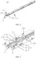
- a mobile phone is used as an example.
- the mobile phone may include a first housing 101 and a second housing 102 that are connected via a hinge 10. Under an action of the hinge 10, actions such as relative rotation and movement can be generated between the first housing 101 and the second housing 102.
- a flexible display 103 (for example, an OLED screen) may be disposed on a surface of the first housing 101 and a surface of the second housing 102.
- the flexible display 103 may provide a large display area and a large operation area, to improve use performance.
- the flexible display 103 may be located on an outer surface of the mobile phone, so that a size of the mobile phone can be reduced for improving portable performance of the mobile phone.
- the flexible display 103 When the mobile phone is in an unfolded state, the flexible display 103 is unfolded accordingly, to provide a large display size and a large touch size. In an actual use process, the flexible display 103 is touched or pressed by a human hand. Therefore, a corresponding component needs to provide effective planar support for the flexible display 103, to prevent the flexible display 103 from being pressed and causing deformation, crack, or the like. In a current mobile phone, some hinges 10 cannot effectively support the flexible display 103, and therefore, reliability of using the flexible display 103 is reduced. Alternatively, in some current hinges 10, to provide good support for the flexible display 103, an additional component like a support needs to be used, and consequently complex structures, a large quantity of parts, and other problems occur.
- this application provides a hinge 10 that has a simple structure and can effectively support a flexible display.
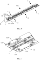
- the hinge 10 may include a main shaft 11, and a first foldable assembly 12 and a second foldable assembly 13 that are symmetrically disposed with respect to the main shaft 11.
- the first foldable assembly 12 and the second foldable assembly 13 may rotate toward or away from each other, to implement a folding function of the hinge 10.
- the first foldable assembly 12 includes a first rotating member 121, a first body 122, and a first connecting rod 123.
- the first rotating member 121 is rotatably connected to the main shaft 11, and is slidably connected to the first body 122.
- the second foldable assembly 13 includes a second rotating member 131, a second body 132, and a second connecting rod 133.
- the second rotating member 131 is rotatably connected to the main shaft 11, and is slidably connected to the second body 132.
- one end of the first connecting rod 123 is rotatably connected to the first body 122, and the other end of the first connecting rod 123 is rotatably connected to the second rotating member 131.
- One end of the second connecting rod 133 is rotatably connected to the second body 132, and the other end of the second connecting rod 133 is rotatably connected to the first rotating member 121.
- the hinge 10 is in an unfolded state.
- the first body 122 has a first support surface 1220
- the second body 132 has a second support surface 1320.
- the first support surface 1220 and the second support surface 1320 are located on a same plane.
- the first support surface 1220 and the second support surface 1320 can provide good planar support.
- the first support surface 1220 and the second support surface 1320 can effectively support the flexible display, so as to effectively prevent deformation of the flexible display, and effectively ensure use security of the flexible display and user experience.
- the main shaft 11 may have a third support surface 110 for the hinge 10 to provide a good support effect for the flexible display. When the hinge 10 is in the unfolded state, the first support surface 1220, the second support surface 1320, and the third support surface 110 are located on a same plane.
- the first support surface 1220, the second support surface 1320, and the third support surface 110 all can provide good planar support for the flexible display, so that use security of the flexible display and user experience can be effectively ensured.
- the third support surface 110 can connect the first support surface 1220 and the second support surface 1320, so that a coherent support plane can be formed.
- the third support surface 110 may be a flat surface, or may be a curved surface with a small curvature. Alternatively, the third support surface 110 may be a surface that is partially a flat surface and partially a curved surface. In an actual application, a shape of the third support surface 110 may be adaptively adjusted based on an actual requirement. Details are not described herein.
- the hinge 10 in an outward-foldable mobile phone, is located inside the flexible display 103.
- a rotation radius of the hinge 10 is less than a rotation radius of the flexible display 103.
- a length of the hinge 10 can change in the process of folding or unfolding the mobile phone, to prevent the hinge 10 from stretching or compressing the flexible display 103.
- the length of the hinge 10 in the process of folding the mobile phone, can be shortened, so that an action force of stretching the flexible display 103 can be avoided.
- the length of the hinge 10 In the process of unfolding the mobile phone, the length of the hinge 10 can be increased, so that an action force of compressing the flexible display 103 can be avoided.
- the first rotating member 121 and the second rotating member 131 can generate a rotation motion relative to the main shaft 11.
- the first body 122 is slidably connected to the first rotating member 121
- the second body 132 is slidably connected to the second rotating member 131. Therefore, when the first rotating member 121 and the second rotating member 131 rotate relative to each other, the first body 122 and the second body 132 can generate a sliding action; and when the first body 122 and the second body 132 generate the sliding action, a connection length among the first body 122, the main shaft 11, and the second body 132 can be increased or shortened. Specifically, as shown in FIG. 3 to FIG.
- first foldable assembly 12 and the second foldable assembly 13 rotate toward each other means that the first foldable assembly 12 rotates and moves in a direction of the second foldable assembly 13, and the second foldable assembly 13 rotates and moves in a direction of the first foldable assembly 12.
- the first foldable assembly 12 and the second foldable assembly 13 rotate away from each other, the first rotating member 121 and the first body 122 rotate synchronously, and the second rotating member 131 and the second body 132 rotate synchronously.
- the first rotating member 121 is configured to enable the second body 132 to be away from the main shaft 11 via the first connecting rod 123
- the second rotating member 131 is configured to enable the first body 122 to be away from the main shaft 11 via the second connecting rod 133.
- the length of the hinge 10 can be increased. It should be noted that rotation away from each other means that two parts rotate and move in directions away from each other.
- first foldable assembly 12 and the second foldable assembly 13 rotate away from each other means that the first foldable assembly 12 rotates and moves in a direction away from the second foldable assembly 13, and the second foldable assembly 13 rotates and moves in a direction away from the first foldable assembly 12.
- a folding function of the hinge 10 may be implemented via the main shaft 11, the first rotating member 121, the first body 122, the first connecting rod 123, the second rotating member 131, the second body 132, and the second connecting rod 133.
- the length of the hinge 10 may further change, to avoid an action force of stretching or compressing the flexible display.
- the hinge 10 uses a small quantity of parts, and has a simple structure, so that manufacturing costs and assembling costs of the hinge 10 can be effectively reduced.
- first foldable assemblies 12 and three second foldable assemblies 13 are disposed in a length direction of the main shaft 11.
- a structure of each first foldable assembly 12 is basically the same.
- a structure of each second foldable assembly 13 is also basically the same.
- the first foldable assembly 12 and the second foldable assembly 13 are disposed in a one-to-one correspondence.
- a plurality of first foldable assemblies 12 and a plurality of second foldable assemblies 13 are used to effectively improve structural strength and stability of the hinge 10 during use.
- each first foldable assembly 12 has a first support surface 1220, and first support surfaces 1220 of a plurality of first foldable assemblies 12 are located on a same plane.
- each second foldable assembly 13 has a second support surface 1320, and second support surfaces 1320 of a plurality of second foldable assemblies 123 are located on a same plane.
- the plurality of first foldable assemblies 12 may be fastened via screws, through welding, or the like, and the plurality of second foldable assemblies 13 may also be fastened to each other via screws, through welding, or the like. This is not limited in this application.
- the hinge 10 may alternatively include one first foldable assembly 12 and one second foldable assembly 13.
- two or more first foldable assemblies 12 and two or more second foldable assemblies 13 may be included.
- a quantity of disposed first foldable assemblies 12 and a quantity of disposed second foldable assemblies 13 are not limited in this application.
- the hinge 10 includes one first foldable assembly 12 and one second foldable assembly 13 for specific description.
- the main shaft 11 may have various structure types.
- the main shaft 11 may include a first shaft body 111 and a second shaft body 112.
- first rotating member 121 and the main shaft 11 may be rotatably connected via a cylindrical structure.
- the first shaft body 111 has a convex first cylindrical surface 1111
- the second shaft body 112 has a concave second cylindrical surface 1121
- the first cylindrical surface 1111 and the second cylindrical surface 1121 are disposed opposite to each other.
- the first rotating member 121 has a first arc-shaped arm 1211, and the first arc-shaped arm 1211 is located in first arc-shaped space formed by the first cylindrical surface 1111 and the second cylindrical surface 1121.
- an inner concave surface (not shown in the figure) of the first arc-shaped arm 1211 is attached to the first cylindrical surface 1111
- an outer convex surface (not shown in the figure) of the first arc-shaped arm 1211 is attached to the second cylindrical surface 1121, to implement a rotatable connection between the first rotating member 121 and the main shaft 11.
- an axis center of the first arc-shaped arm 1211, an axis center of the first cylindrical surface 1111, and an axis center of the second cylindrical surface 1121 all coincide. It should be noted that an arc-shaped arm refers to a part that is of a circular ring and that is cut by a sector, and both an inner concave surface and an outer convex surface of the arc-shaped arm are cylindrical surfaces.
- the first arc-shaped arm 1211 of the first rotating member 121 is limited to the first arc-shaped space formed by the first cylindrical surface 1111 and the second cylindrical surface 1121 of the main shaft 11, so that the first arc-shaped arm 1211 of the first rotating member 121 can rotate and move only in the first arc-shaped space formed by the first cylindrical surface 1111 and the second cylindrical surface 1121.
- the main shaft 11 further has a stop surface 113a and a stop surface 113b that are disposed opposite to each other, to prevent the first rotating member 121 from sliding in an axial direction of the main shaft 11.
- the stop surface 113a is configured to fit an end surface 1211a of the first arc-shaped arm
- the stop surface 113b is configured to fit an end surface 1211b of the first arc-shaped arm, so that the first rotating member 121 can be prevented from sliding in the axial direction of the main shaft 11.
- one part of the stop surface 113a is located in the first shaft body 111, and the other part of the stop surface 113a is located in the second shaft body 112.
- One part of the stop surface 113b is located in the first shaft body 111, and the other part of the stop surface 113b is located in the second shaft body 112.
- the stop surface 113a may also be completely disposed in the first shaft body 111, or the stop surface 113a may also be completely disposed in the second shaft body 112.
- the stop surface 113b may also be completely disposed in the first shaft body 111, or the stop surface 113b may also be completely disposed in the second shaft body 112.
- another structure may be disposed to prevent the first rotating member 121 from sliding in the axial direction. This is not specifically limited in this application.
- structures of the first rotating member 121 and the second rotating member 131 are basically the same.
- a structure that is in the main shaft 11 and that is configured to connect to the first rotating member 121 is also basically the same as a structure that is in the main shaft 11 and that is configured to connect to the second rotating member 131.
- the second rotating member 131 has a second arc-shaped arm 1311, and the second arc-shaped arm 1311 is located in second arc-shaped space formed by a third cylindrical surface 1112 and a fourth cylindrical surface 1122.
- an inner concave surface (not shown in the figure) of the second arc-shaped arm 1311 is attached to the third cylindrical surface 1112
- an outer convex surface (not shown in the figure) of the second arc-shaped arm 1311 is attached to the fourth cylindrical surface 1122, to implement a rotatable connection between the second rotating member 131 and the main shaft 11.
- An axis center of the second arc-shaped arm 1311, an axis center of the third cylindrical surface 1112, and an axis center of the fourth cylindrical surface 1122 all coincide.
- the main shaft 11 further has a stop surface 114a and a stop surface 114b that are disposed opposite to each other.
- the stop surface 114a is configured to fit an end surface 1311a of the second arc-shaped arm
- the stop surface 114b is configured to fit an end surface 1311b of the second arc-shaped arm, so that the first rotating member 121 can be prevented from sliding in the axial direction of the main shaft 11.
- the hinge 10 is in an unfolded state.
- the first arc-shaped arm 1211 rotates out of the first arc-shaped space
- the second arc-shaped arm 1311 rotates out of the second arc-shaped space. That the first arc-shaped arm 1211 rotates out of the first arc-shaped space may be understood as that a part of the first arc-shaped arm 1211 in the second arc-shaped space decreases. That the second arc-shaped arm 1311 rotates out of the second arc-shaped space may be understood as that a part of the second arc-shaped arm 1311 in the second arc-shaped space decreases. It can be seen from FIG. 10 that the first arc-shaped arm 1211 rotates anticlockwise.
- the first arc-shaped arm 1211 rotates into the first arc-shaped space
- the second arc-shaped arm 1311 rotates into the second arc-shaped space.
- the rotation-into means that the first arc-shaped arm 1211 is gradually rotated into the second arc-shaped space, and the part of the first arc-shaped arm 1211 in the second arc-shaped space increases.
- one part of the stop surface 114a is located in the first shaft body 111, and the other part of the stop surface 114a is located in the second shaft body 112.
- One part of the stop surface 114b is located in the first shaft body 111, and the other part of the stop surface 114b is located in the second shaft body 112.
- the stop surface 114a may also be completely disposed in the first shaft body 111, or the stop surface 114a may also be completely disposed in the second shaft body 112.
- the stop surface 114b may also be completely disposed in the first shaft body 111, or the stop surface 114b may also be completely disposed in the second shaft body 112.
- another structure may be disposed to prevent the first rotating member 121 from sliding in the axial direction. This is not specifically limited in this application.
- first rotating member 121 and the second rotating member 131 are the same. Therefore, the first rotating member 121 and the second rotating member 131 may be replaced with each other, so that assembly difficulty can be reduced, and a manufacturing process can also be simplified.
- the main shaft 11 includes the first shaft body 111 and the second shaft body 112.
- the first shaft body 111 and the second shaft body 112 can be separately manufactured, so that manufacturing time can be shortened.
- the first arc-shaped arm 1211 of the first rotating member 121 may be disposed between the first cylindrical surface 1111 and the second cylindrical surface 1121
- the second arc-shaped arm 1311 of the second rotating member 131 may be disposed between the third cylindrical surface 1112 and the fourth cylindrical surface 1122.
- the first shaft body 111 and the second shaft body 112 are fastened via a fastener like a screw, to implement assembling among the first rotating member 121, the second rotating member 131, the first shaft body 111, and the second shaft body 112.
- the first cylindrical surface 1111 is specifically a semi-cylindrical surface. That is, a surface 1113 that is of the first shaft body 111 and that is away from the first cylindrical surface 1111 is a flat surface.
- the third cylindrical surface 1112 is also a semi-cylindrical surface, that is, a surface 1114 that is of the first shaft body 111 and that is away from the third cylindrical surface 1112 is a flat surface.
- flatness of the hinge 10 is improved.
- the hinge 10 may be a flat surface, which can improve flatness of the hinge 10.
- the hinge 10 After the hinge 10 is used in a foldable mobile phone, when the hinge 10 is in the unfolded state, the back of a flexible display may be attached to the surface 1113 and the surface 1114, so that the flexible display can be effectively supported, and flatness of the flexible display can be improved.
- the axis center of the first cylindrical surface 1111 does not overlap the axis center of the third cylindrical surface 1112.
- a central axis of the first cylindrical surface 1111 may be referred to as a first central axis
- a central axis of the third cylindrical surface 1112 may be referred to as a second central axis.
- the first central axis may be used as a rotation axis center of the first foldable assembly 12, so that the first rotating member 121 of the first foldable assembly 12 can rotate by using the first central axis as the rotation axis center.
- the second central axis may be used as a rotation axis center of the second foldable assembly 13, so that the second rotating member 131 of the second foldable assembly 13 can rotate by using the second central axis as the rotation axis center.
- the first central axis and the second central axis are two central axes that are parallel to each other with a specific spacing.
- the first foldable assembly 12 and the second foldable assembly 13 can have sufficient rotation space, to avoid interference between the first foldable assembly 12 and the second foldable assembly 13.
- two central axes may be provided by a single main shaft 11. Therefore, a quantity of used parts can be reduced.
- the main shaft 11 and the first rotating member 121 may alternatively be rotatably connected via another structure.
- the main shaft 11 and the second rotating member 131 may also be rotatably connected via another structure. Details are not described herein.
- the first body 122 and the first rotating member 121 are slidably connected via structures of a sliding groove and a sliding end.
- the first body 122 has a first sliding groove 1221
- the first rotating member 121 has a first sliding end 1212
- the first sliding end 1212 is slidably disposed in the first sliding groove 1221.
- first sliding groove 1221 and the first sliding end 1212 may be interchanged.
- first sliding end 1212 may be disposed in the first body 122, and the first sliding groove 1221 may be provided in the first rotating member 121. Details are not described herein.
- the second body 132 and the second rotating member 131 are also slidably connected via structures of a sliding groove and a sliding end.
- the second body 132 has a second sliding groove 1321
- the second rotating member 131 has a second sliding end 1312
- the second sliding end 1312 is slidably disposed in the second sliding groove 1321.
- first sliding end 1212 slides into the first sliding groove 1221, and the second sliding end 1312 slides into the second sliding groove 1321. That the first sliding end 1212 slides into the first sliding groove 1221 may be understood as that a part of the first sliding end 1212 in the first sliding groove 1221 increases; and that the second sliding end 1312 slides into the second sliding groove 1321 may be understood as that a part of the second sliding end 1312 in the second sliding groove 1321 increases.
- first sliding end 1212 slides out of the first sliding groove 1221, and the second sliding end 1312 slides out of the second sliding groove 1321. That the first sliding end 1212 slides out of the first sliding groove 1221 may be understood as that a part of the first sliding end 1212 in the first sliding groove 1221 decreases; and that the second sliding end 1312 slides out of the second sliding groove 1321 may be understood as that a part of the second sliding end 1312 in the second sliding groove 1321 decreases.
- disposing positions of the second sliding groove 1321 and the second sliding end 1312 may be interchanged.
- the second sliding end 1312 may be disposed in the second body 132, and the second sliding groove 1321 may be provided in the second rotating member 131. Details are not described herein.
- first body 122 and the first rotating member 121 may alternatively be slidably connected via another structure form.
- second body 132 and the second rotating member 131 may alternatively be slidably connected via another structure form. This is not limited in this application.
- the first foldable assembly 12 further includes a first suspension assembly 14, so that a suspension function at a folding angle can be implemented.
- the first rotating member 121 has a first mounting groove 1213, and the first suspension assembly 14 is disposed in the first mounting groove 1213.
- the first suspension assembly 14 is in sliding contact with the first body 122, and is configured to provide a damping force when the first rotating member 121 and the first body 122 slide relative to each other.
- the first mounting groove 1213 configured to accommodate the first suspension assembly 14 is provided in the first rotating member 121, so that compactness of the first foldable assembly 12 can be improved, and a miniaturization design of the hinge 10 can be implemented.
- the first suspension assembly 14 When the first suspension assembly 14 is set, the first suspension assembly 14 may have various structure types.
- the first suspension assembly 14 includes a suspension member 141, a suspension member 142, a first spring 143, and a second spring 144.
- the suspension member 141 has a protrusion 1411, a positioning post 1412, and a positioning post 1413.
- the suspension member 142 has a protrusion 1421, a positioning post 1422, and a positioning post 1423.
- One end of the first spring 143 is sleeved on a periphery of the positioning post 1412, and the other end of the first spring 143 is sleeved on a periphery of the positioning post 1422.
- One end of the second spring 144 is sleeved on a periphery of the positioning post 1413, and the other end of the second spring 144 is sleeved on a periphery of the positioning post 1423.
- the protrusion 1411 of the suspension member 141 and the protrusion 1421 of the suspension member 142 can elastically abut against an inner wall of the first sliding groove 1221.
- the first rotating member 121 can drive the first suspension assembly 14 to move synchronously, so that the protrusion 1411, the protrusion 1421, and the inner wall of the first sliding groove 1221 have relative friction; and under an effect of a friction force, a damping force for the hinge 10 during folding or unfolding can be provided.
- the inner wall of the first sliding groove 1221 further has a recessed part (not marked in the figure). After the protrusion 1411 and the protrusion 1421 slide into the recessed part, a sliding position between the first rotating member 121 and the first body 122 may be maintained, to implement a suspension function of the hinge 10.
- the hinge 10 is in an unfolded state, so that a mobile phone can be prevented from being folded randomly, and user experience can be improved.
- the hinge 10 is in a fully-folded state, so that the mobile phone can be prevented from being unfolded randomly, and security of the mobile phone is ensured.
- a plurality of recessed parts may be disposed, to implement a suspension function of the hinge 10 at a plurality of different angles.
- the first suspension assembly 14 may alternatively use a current commonly-used type. Details are not described herein.
- the hinge 10 may further include a second suspension assembly 15.
- a structure of the second suspension assembly 15 is basically the same as that of the first suspension assembly 14.
- the second rotating member 131 has a second mounting groove 1313, and the second suspension assembly 15 is disposed in the second mounting groove 1313.
- the second suspension assembly 15 is in sliding contact with the second body 132, and is configured to provide a damping force when the second rotating member 131 and the second body 132 slide relative to each other.
- the second suspension assembly 15 includes a suspension member 151, a suspension member 152, a first spring 153, and a second spring 154.
- a structure of the second suspension assembly 15 is basically the same as that of the first suspension assembly 14. A specific structure of the second suspension assembly 15 is described herein in detail.
- the first connecting rod 123 is rotatably connected to the first body 122 and the second rotating member 131 in a plurality of manners.
- one end of the first connecting rod 123 has a pin hole 1231
- the first body 122 has a pin hole 1222
- a pin shaft 16 is fastened in the pin hole 1231 and the pin hole 1222 through penetration, to implement a rotatable connection between the first connecting rod 123 and the first body 122.
- first connecting rod 123 has a pin hole 1232
- second rotating member 131 has a pin hole 1314
- the pin shaft 17 is fastened in the pin hole 1232 and the pin hole 1314 through penetration, to implement a rotatable connection between the first connecting rod 123 and the second rotating member 131.
- first connecting rod 123, the first body 122, and the second rotating member 131 may also be rotatably connected via a current commonly-used structure. Details are not described herein.
- a structure of the first connecting rod 123 is basically the same as that of the second connecting rod 133.
- a connection structure among the second connecting rod 133, the second body 132, and the first rotating member 121 is basically the same as a connection structure among the first connecting rod 123, the first body 122, and the second rotating member 131. Details are not described herein.
- the first connecting rod 123 of the first foldable assembly 12 is rotatably connected to the second rotating member 131 of the second foldable assembly 13, and the second connecting rod 133 of the second foldable assembly 13 is rotatably connected to the first rotating member 121 of the first foldable assembly 12. Therefore, when the hinge 10 is folded or unfolded, the first foldable assembly 12 and the second foldable assembly 13 can move synchronously.
- the hinge 10 further includes a synchronization assembly.
- the synchronization assembly can enhance synchronization between the first foldable assembly 12 and the second foldable assembly 13, and can ensure smoothness of the hinge 10 during folding or unfolding.
- the synchronization assembly may include a first synchronization member 181 and a second synchronization member 182.
- the first synchronization member 181 is rotatably connected to the main shaft 11, and a rotation axis center of the first synchronization member 181 coincides with a rotation axis center of the first rotating member 121.
- the second synchronization member 182 is rotatably connected to the main shaft 11, and a rotation axis center of the second synchronization member 182 coincides with a rotation axis center of the second rotating member 131.
- the first synchronization member 181 has a first tooth-shaped part 1811 and a first sliding end 1812
- the second synchronization member 182 has a second tooth-shaped part 1821 and a second sliding end 1822.
- the first tooth-shaped part 1811 is engaged with the second tooth-shaped part 1821
- the first sliding end 1812 is slidably connected to the sliding groove 1223 in the first body 122
- the second sliding end 1822 is slidably connected to the sliding groove 1323 in the second body 132.
- synchronous reverse rotation between the first synchronization member 181 and the second synchronization member 182 can be implemented through meshing between the first tooth-shaped part 1811 and the second tooth-shaped part 1821.
- smoothness of the hinge 10 during folding or unfolding can be improved. This helps improve user experience.
- the synchronous reverse rotation means that two parts have a same rotation speed and opposite rotation directions.
- a plurality of foregoing synchronization assemblies may be disposed in the hinge 10.
- a quantity of disposed synchronization assemblies is not limited in this application.
- FIG. 13 is a diagram of a structure of a back side (for example, a side away from a flexible display) of the hinge 10.
- the hinge 10 further includes a cover assembly 19.
- the cover assembly 19 includes a first plate body 191, a second plate body 192, and a third plate body 193.
- the first plate body 191 is fastened to the first rotating member 121
- the second plate body 192 is fastened to the second rotating member 131
- the third plate body 193 is fastened to the main shaft 11.
- the cover assembly 19 can be disposed to effectively shield and protect some parts (such as the first rotating member, the second rotating member, the first suspension assembly, and the second suspension assembly) in the hinge 10 for effectively shielding an external foreign matter. This can improve use safety of the hinge 10.
- the cover assembly 19 further helps improve integration of the foldable electronic device.
- FIG. 14 is a diagram of a structure of a front side of a foldable electronic device on which no flexible display is disposed.
- FIG. 16 is a diagram of a structure of a rear side of the foldable electronic device.
- the foldable electronic device includes a first housing 101 and a second housing 102, and a flexible display 103 (for example, an OLED screen) may be disposed on surfaces (for example, lower surfaces in FIG. 16 ) of the first housing 101 and the second housing 102.
- a flexible display 103 for example, an OLED screen
- the first housing 101 has a first mounting surface 1010
- the second housing 102 has a second mounting surface 1020
- a back side of a flexible display is attached to the first mounting surface 1010 and the second mounting surface 1020, to implement fastening among the flexible display, the first housing 101, and the second housing 102.
- the hinge When the hinge is in an unfolded state, the first mounting surface 1010, the second mounting surface 1020, the first support surface 1220, the second support surface 1320, and the third support surface 110 are located on a same plane.
- adjacent edges of the first mounting surface 1010 and the first support surface 1220 are spliced with each other
- adjacent edges of the second mounting surface 1020 and the second support surface 1320 are spliced with each other.
- the first mounting surface 1010, the second mounting surface 1020, the first support surface 1220, and the second support surface 1320 can all provide a good plane for the flexible display.
- the first mounting surface 1010, the second mounting surface 1020, the first support surface 1220, and the second support surface 1320 can all effectively support the flexible display, so as to effectively prevent deformation of the flexible display, and effectively ensure use security of the flexible display and user experience.
- the adjacent edges of the first mounting surface 1010 and the first support surface 1220 are spliced with each other, a case in which a support effect for the flexible display is reduced as there is an obvious gap between the first mounting surface 1010 and the first support surface 1220 can be effectively avoided.
- the flexible display 103 may be fastened on the third support surface 110 through bonding, or the like, to implement fastening between the flexible display 103 and the third support surface 110.
- the flexible display 103 may be lapped on the third support surface 110, that is, the flexible display 103 and the third support surface 110 are not in a fastening relationship, and the third support surface 110 may only support the flexible display 103.
- the first body 122 is fastened to the first housing 101. Therefore, in processes of folding and unfolding the hinge 10, relative positions between the first support surface 1220 and the first mounting surface 1020 do not change. Therefore, effective assembling can be maintained for providing a coherent support plane for the flexible display.
- the second body 132 is fastened to the second housing 102. Therefore, in the processes of folding and unfolding the hinge 10, relative positions between the second support surface 1320 and the second mounting surface 1030 do not change. Therefore, effective assembling can be maintained for providing a coherent support plane for the flexible display.
- a back side of the foldable electronic device can also be effectively assembled.
- the first plate body 191 in the cover assembly 19 is effectively spliced with the first housing 101
- the second plate body 192 is effectively spliced with the second housing 102, thereby improving integration of the back side of the foldable electronic device, and preventing external impurities such as dust from entering the foldable electronic device.
- an action such as slip may occur between the first plate body 191 and the first housing 101, and an action such as slip may occur between the second plate body 192 and the second housing 102. Therefore, as shown in FIG. 17 , in the example provided in this application, the first housing 101 has space 1011 for the first plate body 191 to slide, and the second housing 102 has space 1021 for the second plate body 192 to slide.
- the first plate body 191 almost occupies the entire space 1011
- the second plate body 192 almost occupies the entire space 1021.
Landscapes
- Engineering & Computer Science (AREA)
- Theoretical Computer Science (AREA)
- General Engineering & Computer Science (AREA)
- Computer Hardware Design (AREA)
- Physics & Mathematics (AREA)
- General Physics & Mathematics (AREA)
- Signal Processing (AREA)
- Human Computer Interaction (AREA)
- Mechanical Engineering (AREA)
- Mathematical Physics (AREA)
- Microelectronics & Electronic Packaging (AREA)
- Telephone Set Structure (AREA)
- Pivots And Pivotal Connections (AREA)
Applications Claiming Priority (2)
| Application Number | Priority Date | Filing Date | Title |
|---|---|---|---|
| CN202211629602.4A CN118224173B (zh) | 2022-12-19 | 2022-12-19 | 一种可折叠电子设备和铰链 |
| PCT/CN2023/134281 WO2024131443A1 (zh) | 2022-12-19 | 2023-11-27 | 一种可折叠电子设备和铰链 |
Publications (2)
| Publication Number | Publication Date |
|---|---|
| EP4550765A1 true EP4550765A1 (de) | 2025-05-07 |
| EP4550765A4 EP4550765A4 (de) | 2025-12-03 |
Family
ID=91504482
Family Applications (1)
| Application Number | Title | Priority Date | Filing Date |
|---|---|---|---|
| EP23905611.2A Pending EP4550765A4 (de) | 2022-12-19 | 2023-11-27 | Faltbare elektronische vorrichtung und scharnier |
Country Status (4)
| Country | Link |
|---|---|
| US (1) | US20260019480A1 (de) |
| EP (1) | EP4550765A4 (de) |
| CN (1) | CN118224173B (de) |
| WO (1) | WO2024131443A1 (de) |
Family Cites Families (13)
| Publication number | Priority date | Publication date | Assignee | Title |
|---|---|---|---|---|
| JP2013118437A (ja) * | 2011-12-01 | 2013-06-13 | Kyocera Corp | 折り畳み式電子機器 |
| CN110248002B (zh) * | 2019-06-04 | 2024-11-26 | 东莞市环力智能科技有限公司 | 一种外侧柔性屏电子设备 |
| CN112230714A (zh) * | 2019-07-15 | 2021-01-15 | 深圳市柔宇科技有限公司 | 电子设备 |
| CN110784570B (zh) * | 2019-10-29 | 2021-04-09 | Oppo广东移动通信有限公司 | 折叠装置及电子设备 |
| CN112995368B (zh) * | 2019-12-13 | 2021-12-21 | 华为技术有限公司 | 一种铰链和移动终端 |
| US12135589B2 (en) * | 2020-01-21 | 2024-11-05 | Google Llc | Double-axis soft hinge mechanism and foldable device having same |
| CN113805646B (zh) * | 2020-06-15 | 2024-01-30 | 华为技术有限公司 | 折叠装置及电子设备 |
| CN113833741B (zh) * | 2020-06-24 | 2023-04-07 | 华为技术有限公司 | 一种折叠装置及电子设备 |
| CN114251347A (zh) * | 2020-09-23 | 2022-03-29 | 深圳市柔宇科技股份有限公司 | 转轴组件及可折叠电子设备 |
| CN114338865B (zh) * | 2020-09-30 | 2025-06-03 | 华为技术有限公司 | 一种折叠装置及可折叠电子设备 |
| CN115150486B (zh) * | 2021-03-31 | 2024-03-26 | 华为技术有限公司 | 折叠电子设备 |
| CN113669357B (zh) * | 2021-08-09 | 2022-11-01 | 武汉华星光电半导体显示技术有限公司 | 折叠式铰链及折叠式显示装置 |
| CN117869455A (zh) * | 2022-08-24 | 2024-04-12 | Oppo广东移动通信有限公司 | 折叠装置、壳体组件、电子设备及可折叠的电子设备 |
-
2022
- 2022-12-19 CN CN202211629602.4A patent/CN118224173B/zh active Active
-
2023
- 2023-11-27 US US18/995,576 patent/US20260019480A1/en active Pending
- 2023-11-27 WO PCT/CN2023/134281 patent/WO2024131443A1/zh not_active Ceased
- 2023-11-27 EP EP23905611.2A patent/EP4550765A4/de active Pending
Also Published As
| Publication number | Publication date |
|---|---|
| CN118224173A (zh) | 2024-06-21 |
| EP4550765A4 (de) | 2025-12-03 |
| WO2024131443A1 (zh) | 2024-06-27 |
| US20260019480A1 (en) | 2026-01-15 |
| CN118224173B (zh) | 2026-02-03 |
Similar Documents
| Publication | Publication Date | Title |
|---|---|---|
| US12314091B2 (en) | Folding mechanism and electronic device | |
| US11467633B2 (en) | Hinge and mobile terminal | |
| CN115370655A (zh) | 转动模组和电子设备 | |
| WO2022068290A1 (zh) | 折叠装置及可折叠的电子设备 | |
| CN112602141A (zh) | 连接装置及可弯曲设备 | |
| CN112513773A (zh) | 一种框架模组及可弯曲终端 | |
| EP4354835A1 (de) | Klappmechanismus und elektronische vorrichtung | |
| JP2025504960A (ja) | ヒンジ機構および電子デバイス | |
| EP4477900A1 (de) | Drehwellenmechanismus und elektronische vorrichtung | |
| EP4488535A1 (de) | Drehwellenmechanismus und elektronische vorrichtung | |
| CN111866221A (zh) | 一种铰链及移动终端 | |
| EP4481213A1 (de) | Drehwellenmechanismus und elektronische vorrichtung | |
| EP4279755A1 (de) | Drehmechanismus und klappbare elektronische vorrichtung | |
| EP4474662A1 (de) | Scharniermechanismus und elektronische vorrichtung | |
| US20240402758A1 (en) | Hinge and foldable display device | |
| EP4550765A1 (de) | Faltbare elektronische vorrichtung und scharnier | |
| US20240418208A1 (en) | Hinge Mechanism and Electronic Device | |
| JP2025522312A (ja) | ヒンジ機構及び電子デバイス | |
| EP4529143A1 (de) | Elektronische vorrichtung und klappmechanismus | |
| EP4528118A1 (de) | Drehwellenmechanismus und elektronische vorrichtung | |
| CN118274012B (zh) | 一种转轴机构及电子设备 | |
| CN219655079U (zh) | 一种转轴组件和可折叠电子设备 | |
| CN220980100U (zh) | 转轴机构及折叠式电子设备 | |
| EP4545813A1 (de) | Faltbare elektronische vorrichtung und drehwellenmechanismus dafür | |
| EP4560157A1 (de) | Drehwellenmechanismus und elektronische vorrichtung |
Legal Events
| Date | Code | Title | Description |
|---|---|---|---|
| STAA | Information on the status of an ep patent application or granted ep patent |
Free format text: STATUS: THE INTERNATIONAL PUBLICATION HAS BEEN MADE |
|
| PUAI | Public reference made under article 153(3) epc to a published international application that has entered the european phase |
Free format text: ORIGINAL CODE: 0009012 |
|
| STAA | Information on the status of an ep patent application or granted ep patent |
Free format text: STATUS: REQUEST FOR EXAMINATION WAS MADE |
|
| 17P | Request for examination filed |
Effective date: 20250128 |
|
| AK | Designated contracting states |
Kind code of ref document: A1 Designated state(s): AL AT BE BG CH CY CZ DE DK EE ES FI FR GB GR HR HU IE IS IT LI LT LU LV MC ME MK MT NL NO PL PT RO RS SE SI SK SM TR |
|
| REG | Reference to a national code |
Ref country code: DE Ref legal event code: R079 Free format text: PREVIOUS MAIN CLASS: H04M0001020000 Ipc: G06F0001160000 |
|
| A4 | Supplementary search report drawn up and despatched |
Effective date: 20251103 |
|
| RIC1 | Information provided on ipc code assigned before grant |
Ipc: G06F 1/16 20060101AFI20251028BHEP Ipc: H04M 1/02 20060101ALI20251028BHEP Ipc: G09F 9/30 20060101ALI20251028BHEP |