EP4550618A1 - Verfahren und vorrichtung zur steuerung des batterieladens - Google Patents
Verfahren und vorrichtung zur steuerung des batterieladens Download PDFInfo
- Publication number
- EP4550618A1 EP4550618A1 EP24832163.0A EP24832163A EP4550618A1 EP 4550618 A1 EP4550618 A1 EP 4550618A1 EP 24832163 A EP24832163 A EP 24832163A EP 4550618 A1 EP4550618 A1 EP 4550618A1
- Authority
- EP
- European Patent Office
- Prior art keywords
- charge
- map
- battery
- maps
- optimal
- Prior art date
- Legal status (The legal status is an assumption and is not a legal conclusion. Google has not performed a legal analysis and makes no representation as to the accuracy of the status listed.)
- Pending
Links
Images


Classifications
-
- H—ELECTRICITY
- H02—GENERATION; CONVERSION OR DISTRIBUTION OF ELECTRIC POWER
- H02J—ELECTRIC POWER NETWORKS; CIRCUIT ARRANGEMENTS OR SYSTEMS FOR SUPPLYING OR DISTRIBUTING ELECTRIC POWER; SYSTEMS FOR STORING ELECTRIC ENERGY
- H02J7/00—Circuit arrangements for charging or discharging batteries or for supplying loads from batteries
- H02J7/90—Regulation of charging or discharging current or voltage
- H02J7/92—Regulation of charging or discharging current or voltage with prioritisation of loads or sources
-
- H—ELECTRICITY
- H02—GENERATION; CONVERSION OR DISTRIBUTION OF ELECTRIC POWER
- H02J—ELECTRIC POWER NETWORKS; CIRCUIT ARRANGEMENTS OR SYSTEMS FOR SUPPLYING OR DISTRIBUTING ELECTRIC POWER; SYSTEMS FOR STORING ELECTRIC ENERGY
- H02J7/00—Circuit arrangements for charging or discharging batteries or for supplying loads from batteries
- H02J7/80—Circuit arrangements for charging or discharging batteries or for supplying loads from batteries including monitoring or indicating arrangements
-
- H—ELECTRICITY
- H02—GENERATION; CONVERSION OR DISTRIBUTION OF ELECTRIC POWER
- H02J—ELECTRIC POWER NETWORKS; CIRCUIT ARRANGEMENTS OR SYSTEMS FOR SUPPLYING OR DISTRIBUTING ELECTRIC POWER; SYSTEMS FOR STORING ELECTRIC ENERGY
- H02J7/00—Circuit arrangements for charging or discharging batteries or for supplying loads from batteries
- H02J7/90—Regulation of charging or discharging current or voltage
- H02J7/96—Regulation of charging or discharging current or voltage in response to battery voltage
-
- H—ELECTRICITY
- H02—GENERATION; CONVERSION OR DISTRIBUTION OF ELECTRIC POWER
- H02J—ELECTRIC POWER NETWORKS; CIRCUIT ARRANGEMENTS OR SYSTEMS FOR SUPPLYING OR DISTRIBUTING ELECTRIC POWER; SYSTEMS FOR STORING ELECTRIC ENERGY
- H02J7/00—Circuit arrangements for charging or discharging batteries or for supplying loads from batteries
- H02J7/90—Regulation of charging or discharging current or voltage
- H02J7/971—Regulation of charging or discharging current or voltage the charge cycle being controlled or terminated in response to non-electric parameters
- H02J7/975—Regulation of charging or discharging current or voltage the charge cycle being controlled or terminated in response to non-electric parameters in response to temperature
- H02J7/977—Regulation of charging or discharging current or voltage the charge cycle being controlled or terminated in response to non-electric parameters in response to temperature of the battery
-
- B—PERFORMING OPERATIONS; TRANSPORTING
- B60—VEHICLES IN GENERAL
- B60L—PROPULSION OF ELECTRICALLY-PROPELLED VEHICLES; SUPPLYING ELECTRIC POWER FOR AUXILIARY EQUIPMENT OF ELECTRICALLY-PROPELLED VEHICLES; ELECTRODYNAMIC BRAKE SYSTEMS FOR VEHICLES IN GENERAL; MAGNETIC SUSPENSION OR LEVITATION FOR VEHICLES; MONITORING OPERATING VARIABLES OF ELECTRICALLY-PROPELLED VEHICLES; ELECTRIC SAFETY DEVICES FOR ELECTRICALLY-PROPELLED VEHICLES
- B60L2240/00—Control parameters of input or output; Target parameters
- B60L2240/40—Drive Train control parameters
- B60L2240/54—Drive Train control parameters related to batteries
- B60L2240/545—Temperature
-
- B—PERFORMING OPERATIONS; TRANSPORTING
- B60—VEHICLES IN GENERAL
- B60L—PROPULSION OF ELECTRICALLY-PROPELLED VEHICLES; SUPPLYING ELECTRIC POWER FOR AUXILIARY EQUIPMENT OF ELECTRICALLY-PROPELLED VEHICLES; ELECTRODYNAMIC BRAKE SYSTEMS FOR VEHICLES IN GENERAL; MAGNETIC SUSPENSION OR LEVITATION FOR VEHICLES; MONITORING OPERATING VARIABLES OF ELECTRICALLY-PROPELLED VEHICLES; ELECTRIC SAFETY DEVICES FOR ELECTRICALLY-PROPELLED VEHICLES
- B60L53/00—Methods of charging batteries, specially adapted for electric vehicles; Charging stations or on-board charging equipment therefor; Exchange of energy storage elements in electric vehicles
- B60L53/60—Monitoring or controlling charging stations
- B60L53/62—Monitoring or controlling charging stations in response to charging parameters, e.g. current, voltage or electrical charge
-
- H—ELECTRICITY
- H01—ELECTRIC ELEMENTS
- H01M—PROCESSES OR MEANS, e.g. BATTERIES, FOR THE DIRECT CONVERSION OF CHEMICAL ENERGY INTO ELECTRICAL ENERGY
- H01M10/00—Secondary cells; Manufacture thereof
- H01M10/42—Methods or arrangements for servicing or maintenance of secondary cells or secondary half-cells
- H01M10/44—Methods for charging or discharging
Definitions
- the present invention relates to a battery charge control apparatus and method, and more particularly, to a a battery charge control apparatus and method for controlling charging of a battery with an optimal charging method corresponding to a charging objective set by a user.
- a secondary battery is a battery that can be recharged and reused even after being discharged.
- the secondary battery can be used as an energy source for small devices such as mobile phones, tablet PCs and vacuum cleaners, and also used as an energy source for medium and large devices such as an energy storage system (ESS) for automobiles and smart grids.
- ESS energy storage system
- the secondary battery is applied to a system in a form of an assembly such as a battery module in which a plurality of battery cells is connected in series and parallel or a battery pack in which battery modules are connected in series and parallel according to system requirements.
- a high-capacity battery system with multiple battery packs connected in parallel may be applied for medium-to-large devices such as electric vehicles to meet the required capacity of the device.
- a stepwise charging method is mainly used, in which charging is carried out with a high charge current at the beginning of charging and is carried out by gradually reducing the charge current as the SOC (State of Charge) or the voltage value of the battery increases.
- the charge current can be adjusted based on the current temperature of the battery in consideration of safety of charging.
- the charge current value during a battery charging process is determined by a pre-stored charge map or charge profile.
- the battery is charged according to a preset charging method and a user's selection regarding the charging method are limited.
- Some charging devices provide users with choices regarding charge time, charge speed, etc., but the options for selection are very limited.
- the lifespan of the battery may be shortened or the temperature of the battery may exceed the optimal range after charging is completed, resulting in lower output performance.
- embodiments of the present disclosure provide a battery charge control apparatus that controls charging of the battery in an optimal charging method corresponding to a charging objective set by a user.
- embodiments of the present disclosure also provide a method of controlling battery charging using the battery charge control apparatus.
- a battery charge control apparatus may include at least one processor; and a memory configured to store at least one instruction executed by the at least one processor.
- the at least one instruction may include an instruction to, upon receiving user input information including a charging objective, derive a plurality of optimal charge maps that satisfy the charging objective based on battery state information and charger state information; an instruction to output information on each of the derived optimal charge maps through a predefined graphical user interface (GUI); and an instruction to, upon receiving a user selection signal for one of the optimal charge maps, control the battery to be charged using an optimal charge map corresponding to the user selection signal.
- GUI graphical user interface
- the charging objective may include at least one charging objective value including one or more of a target charge amount, a target charge time, and a target battery temperature at the point at which charging is completed; or at least one charge priority item including one or more of the maximum charge amount, the minimum charge time, and the maximum performance.
- the instruction to derive the plurality of optimal charge maps may include an instruction to derive optimal charge maps that satisfy the charging objective among a plurality of pre-stored charge maps.
- the instruction to derive the plurality of optimal charge maps may include an instruction to generate charge prediction information for each of the plurality of pre-stored charge maps using a predefined battery behavior prediction model; and an instruction to select N optimal charge maps that satisfy the charging objective based on the generated charge prediction information.
- the instruction to generate charge prediction information may include an instruction to predict one or more of a charge completion time, the charge amount at the charge completion time, the battery temperature at the charge completion time, and an accumulated amount of polarization values, when charging is performed according to the charge map.
- the instruction to derive the plurality of optimal charge maps may include an instruction to select one or more of a first charge map that allows charging in a minimum time, a second charge map that allows charging with a maximum charge amount, a third charge map that satisfies a predefined maximum performance condition, and a fourth charge map that satisfies a predefined maximum lifespan condition, among the charge maps that satisfy the charging objective.
- the instruction to derive the plurality of optimal charge maps may include an instruction to determine one or more of the first charge map, the third charge map, and the fourth charge map as an optimal charge map, in the instance that the charging objective is the target charge amount or the maximum charge amount; an instruction to determine one or more of the second charge map, the third charge map, and fourth charge map as an optimal charge map, in the instance that the charging objective is the target charge time or the minimum charge time; and an instruction to determine one or more of the first charge map, the second charge map, and the fourth charge map as an optimal charge map, in the instance that the charging objective is the target battery temperature at the charge completion time or the maximum performance.
- the instruction to output information through the GUI may include an instruction to output identification information and charge prediction information for each of the N optimal charge maps.
- the instruction to output information through the GUI may include an instruction to output each of the optimal charge maps according to predefined priorities.
- the instruction to control the battery to be charged may include an instruction to control the battery to be charged using the optimal charge map which is defined as the first priority, in the instance that the user selection signal is not received within a predefined period of time.
- a battery charge control method performed by a battery charge control apparatus, may include, upon receiving user input information including a charging objective, deriving a plurality of optimal charge maps that satisfy the charging objective based on battery state information and charger state information; outputting information on each of the derived optimal charge maps through a predefined graphical user interface (GUI); and upon receiving a user selection signal for one of the optimal charge maps, controlling the battery to be charged using an optimal charge map corresponding to the user selection signal.
- GUI graphical user interface
- the charging objective may include at least one charging objective value including one or more of a target charge amount, a target charge time, and a target battery temperature at the point at which charging is completed; or at least one charge priority item including one or more of the maximum charge amount, the minimum charge time, and the maximum performance.
- the deriving the plurality of optimal charge maps may include deriving optimal charge maps that satisfy the charging objective among a plurality of pre-stored charge maps.
- the deriving the plurality of optimal charge maps may include generating charge prediction information for each of the plurality of pre-stored charge maps using a predefined battery behavior prediction model; and selecting N optimal charge maps that satisfy the charging objective based on the generated charge prediction information.
- the generating charge prediction information may include predicting one or more of a charge completion time, the charge amount at the charge completion time, the battery temperature at the charge completion time, and an accumulated amount of polarization values, when charging is performed according to the charge map.
- the deriving the plurality of optimal charge maps may include selecting one or more of a first charge map that allows charging in a minimum time, a second charge map that allows charging with a maximum charge amount, a third charge map that satisfies a predefined maximum performance condition, and a fourth charge map that satisfies a predefined maximum lifespan condition, among the charge maps that satisfy the charging objective.
- the deriving the plurality of optimal charge maps may include determining one or more of the first charge map, the third charge map, and the fourth charge map as an optimal charge map, in the instance that the charging objective is the target charge amount or the maximum charge amount; determining one or more of the second charge map, the third charge map, and fourth charge map as an optimal charge map, in the instance that the charging objective is the target charge time or the minimum charge time; and determining one or more of the first charge map, the second charge map, and the fourth charge map as an optimal charge map, in the instance that the charging objective is the target battery temperature at the charge completion time or the maximum performance.
- the outputting information through the GUI may include outputting identification information and charge prediction information for each of the N optimal charge maps.
- the outputting information through the GUI may include outputting each of the optimal charge maps according to predefined priorities.
- the controlling the battery to be charged may include controlling the battery to be charged using the optimal charge map which is defined as the first priority, in the instance that the user selection signal is not received within a predefined period of time.
- the embodiments of the present invention as described above may derive optimal charging maps that satisfy the charging goal set by the user and control battery charging through charge map selected by a user, and thus, can improve the user's freedom of choice regarding a charging method, as well as charging efficiency, performance, and residual value of the battery.
- first, second, A, B, and the like may be used herein to describe various elements, these elements should not be limited by these terms. These terms are only used to distinguish one element from another. For example, a first element could be termed a second element, and, similarly, a second element could be termed a first element, without departing from the scope of the present invention.
- the term "and/or" includes combinations of a plurality of associated listed items or any of the plurality of associated listed items.
- a battery cell is a minimum unit that serves to store power and a battery module refers to an assembly in which a plurality of battery cells is electrically connected.
- a battery pack or battery rack refers to a system of a single structure that is assembled by connecting module units in series or in parallel, set by a battery manufacturer, which can be monitored and controlled by a battery management apparatus/system (BMS).
- BMS battery management apparatus/system
- a battery pack or battery rack may include several battery modules and a battery protection unit or any other protection device.
- a battery bank refers to a group of large-scale battery rack systems configured by connecting several racks in parallel.
- a bank BMS for a battery bank may monitor and control rack BMSs, each of which manages a battery rack.
- a battery assembly may include a plurality of electrically connected battery cells, and refers to an assembly that functions as a power supply source by being applied to a specific system or device.
- the battery assembly may mean a battery module, a battery pack, a battery rack, or a battery bank, but the scope of the present invention is not limited to these entities.
- State of charge refers to a current state of charge of a battery, represented in percent points [%]
- SOH State of Health
- FIG. 1 is a block diagram for explaining a battery charging system according to embodiments of the present invention.
- the battery charging system may include a battery assembly 100, a battery charger 200, a battery charge control apparatus 300, and a user interface device 400.
- the battery assembly 100 may include a plurality of battery cells 10, and the battery cells 10 may be electrically connected to each other.
- the battery assembly 100 may be included in an electric means of transportation, such as an electric vehicle, but the scope of the present invention is not limited to these entities.
- the battery charger 200 is a device that is electrically connected to the battery assembly 100 and performs battery charging.
- the battery charger 200 may be included inside a device to which the battery assembly 100 is applied, or may be separately provided outside the device.
- the battery charge control apparatus 300 may determine a charge control value and control the battery charger 200 so that the battery is charged according to the charge control value.
- the charge control value may mean a charge current value, a charge voltage value, or a charge power value applied to the battery assembly 100 or an individual battery 10.
- the battery charge control apparatus 300 may determine a charge control value using a pre-stored charge map.
- the charge map may include data which includes predefined charge control values for each section of battery state values and each section of charge state values.
- the battery charge control apparatus 300 may determine a charge current value corresponding to the current charge state value (SOC value or voltage value) and the current temperature value of the battery in a charge map stored in a storage device, and control the battery charger 200 to charge the batery with the determined charge current value.
- SOC value or voltage value current charge state value
- the battery charger 200 may determine a charge current value corresponding to the current charge state value (SOC value or voltage value) and the current temperature value of the battery in a charge map stored in a storage device, and control the battery charger 200 to charge the batery with the determined charge current value.
- the battery charge control apparatus 300 may include a battery state information collection device that senses state values of the battery, or may be connected to a battery state information collection device.
- the state values of the battery may include a voltage value, a current value, a temperature value, and an SOC of the battery.
- the battery charge control apparatus 300 may be included in a battery system or a battery charger 200.
- the battery charge control apparatus 300 may be provided inside a battery system and implemented in conjunction with a battery management system (BMS), or may be implemented by being included in a control system of a fast/rapid charging device.
- BMS battery management system
- the user interface device 400 is a device that may be operated by a user and may output specific information to a user or receive specific information input from a user through a predefined graphical user interface (GUI).
- GUI graphical user interface
- the user interface device 400 may correspond to a mobile phone or an Audio Video Navigation (AVN) device installed in an electric vehicle.
- APN Audio Video Navigation
- the scope of the present invention is not limited to these entities.
- the user interface device 400 may be connected to the battery charge control apparatus 300 through a network, receive specific information from the battery charge control apparatus 300, display the information through a GUI, and transmit specific information which is received from a user to the battery charge control apparatus 300.
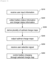
- FIG. 2 is an operational flowchart of a battery charge control method according to embodiments of the present invention.
- the battery charge control apparatus may receive user input information including a charging objective (S210).
- the user interface device may receive user input information including the charging objective from a user through a graphical user interface (GUI). Thereafter, the battery charge control apparatus may receive user input information from the user interface device.
- GUI graphical user interface
- the charging objective may include at least one charging objective value including one or more of a target charge amount (SOC_target), a target charge time (t_target), and a target battery temperature at the point at which charging is completed (T_end_target).
- SOC_target target charge amount
- t_target target charge time
- T_end_target target battery temperature at the point at which charging is completed
- the user interface device may receive input from the user of [SOC 80%] as the target charge amount, [charge time 20 minutes] as the target charge time, or [25 °C] as the target battery temperature, and transmit the input charging objective value to the battery charge control apparatus.
- the charging objective may include at least one charge priority item which includes one or more of the maximum charge amount, the minimum charge time, and the maximum performance.
- the user interface device may receive a charge priority item corresponding to [maximum charge amount], [minimum charge time], or [maximum performance] from the user and transmit the input charge priority item to the battery charge control apparatus.
- the battery charge control apparatus may collect battery status information and charger status information (S220).
- the battery charge control apparatus may check the status information of the battery from a battery management system (BMS) of the battery system and check the status information of the charger from the battery charger.
- BMS battery management system
- the battery status information may include one or more of a battery voltage value, a temperature value, State of charge (SOC), and State of Health (SOH).
- the charger status information may include one or more of the maximum charge current value, the maximum charge voltage value, the maximum charge power value, and the maximum charge time of the battery charger.
- the battery charge control apparatus may derive a plurality of optimal charge maps that satisfy the charging objective input by the user based on the state information of the battery and the state information of the charger (S230).
- the battery charge control apparatus may derive a predefined number (N) of optimal charge maps that satisfy the charging objective among a plurality of charge maps pre-stored in a storage device.
- N predefined number
- the battery charge control apparatus may select N charge maps that can complete charging within 20 minutes when charging is performed using the battery status information and the charger status information as charging conditions among a plurality of pre-stored charging maps and determine the selected charge maps as optimal charge maps.
- the charge map may correspond to data in which predefined charge control values are defined for each section of battery status values and for each section of charge status values.
- FIG. 3 is an example of a charge map according to embodiments of the present invention.
- the charge map may be implemented as a table with predefined charge current values for each SOC section and temperature section.
- the charge current value may be defined as a current value (A) or a charge rate (C-rate).
- the charge map may be implemented as a table with predefined charge control values for each voltage section and temperature section.
- the battery charge control apparatus may derive optimal charge maps using a predefined battery behavior prediction model.
- the battery behavior prediction model may be predefined to receive a charging objective, battery status information, and charger status information as input data and to output charge prediction information for each of the charge maps as output data.
- the charge prediction information may include data indicating battery status information or charging-related information at the point at which charging is completed in the instance that charging is performed according to a specific charge map.
- the charge prediction information may include one or more of the charge completion time, the battery charge amount at the time of charge completion, the battery temperature at the time of charge completion, and the accumulated amount of polarization values.
- the battery behavior prediction model may perform charge simulations for each of the charge maps using the charging objective, the initial state value of the battery, and the limit value of the charger as charging conditions which is input by a user, and predict charge result values for each of the charge maps.
- the battery charge control apparatus may determine the optimal charge map by selecting N charge maps that satisfy the charging objective based on charge prediction information according to the battery behavior prediction model.
- the battery charge control apparatus may select one or more of a first charge map that allows charging in a minimum time (minimum time charge map), a second charge map that allows charging with the maximum charge amount (maximum charge amount charge map), a third charge map (maximum performance charge map) that satisfies a predefined maximum performance condition, and a fourth charge map (maximum lifespan charge map) that satisfies a predefined maximum lifespan condition, among the charge maps that satisfy the charging objective, and may determine the selected charge map as the optimal charge map.
- the battery charge control apparatus may select, among charge maps that can complete charging within 20 minutes, a charge map that allows charging with the maximum charge amount (a second charge map), a charge map with which the battery temperature at the point after charging is ended shows a value closest to the predefined optimal temperature value (a third charge map), and a charge map showing the lowest accumulated polarization value (a fourth charge map), and may determine the selected 3 charge maps as the optimal charge maps.
- a second charge map a charge map that allows charging with the maximum charge amount
- a charge map with which the battery temperature at the point after charging is ended shows a value closest to the predefined optimal temperature value
- a fourth charge map a charge map showing the lowest accumulated polarization value
- the battery charge control apparatus may output information about each of the optimal charge maps derived in S230 through a predefined GUI (S240).
- the battery charge control apparatus may transmit identification information and charge prediction information for each of the derived N optimal charge maps to the user interface device, and the user interface device may display the received information through a predefined GUI.
- the user interface device may output, through a display device, the charge completion time, SOC at the time of charge completion, battery temperature (or performance grade) at the time of charge completion, and the cumulative amount of polarization values (or life effect grade), for each of [maximum charge amount charge map], [maximum performance charge map], and [maximum lifespan charge map].
- the battery charge control apparatus may receive a user selection signal for one of the optimal charge maps from the user interface device (S250).
- the user interface device may receive a selection signal for one of the optimal charge maps from the user through the GUI. Thereafter, the user interface device may transmit the user selection signal to the battery charge control apparatus.
- the battery charge control apparatus may control the battery to be charged through the optimal charge map corresponding to the received user selection signal (S260).
- the battery charge control apparatus may transmit the selected optimal charge map to the battery charger so that the battery is charged according to the optimal charge map.
- the battery charge control apparatus may check a charge control value corresponding to a current state value of the battery in the selected optimal charge map every unit time and may transmit the charge control value to the battery charger, so that the battery can be charged according to the corresponding optimal charge map.
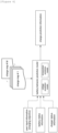
- FIG. 4 is a reference diagram for explaining a battery behavior prediction model according to embodiments of the present invention.
- the battery behavior prediction model may receive a charging objective, battery status information, and charger status information as input data, and output charge predicttion information for each of the charge maps (#1 to #M) as output data.
- the charging objective as a charging target value input by a user, may correspond to a target charge amount (SOC_target), a target charge time (t_target), or a target battery temperature at the point of completion of charging (T_end_target).
- the charging objective as a charge priority item input by a user, may correspond to the maximum charge amount, the minimum charge time, or the maximum performance.
- the battery status information may include one or more of a battery voltage value, a temperature value, SOC, and SOH.
- the charger status information may include one or more of the maximum charge current value, the maximum charge voltage value, the maximum charge power value, and the maximum charge time of the battery charger.
- the M charge maps (#1 to #M) may be pre-stored in a storage device.
- predefined charge maps corresponding to various scenarios may be pre-stored in the storage device. For example, charge maps corresponding to various charger outputs (50kW, 100kW, 250kW, 350kW, etc.), charge maps corresponding to various SOCs at initial charging (0, 20, 40, etc.), charge maps corresponding to various temperatures at initial charging (0, 15, 25, 40, etc.) may be pre-stored in the storage device.
- the battery behavior prediction model may output charge prediction information for each of the stored charge maps (#1 to #M) based on the input data (charging objective, battery status information, charger status information).
- the battery behavior prediction model may proceed with charge simulation according to the charge map (#1) with battery status information as the initial value and calculate the battery voltage value, SOC, amount of heat generation, and accumulated amount of polarization value (difference between a voltage value and an open-circuit voltage value) at every unit time.
- the battery behavior prediction model may change the charge control value at that point to the limit value of the battery charger proceed with charge simulation.
- the battery behavior prediction model may include a predefined voltage prediction model and a temperature prediction model for calculating charging prediction information.
- the voltage prediction model may be predefined to output a battery voltage value, SOC, amount of heat generation (Q), and a polarization value based on the SOC, the SOH, the battery temperature (T), and the charge current value at a previous time point. Additionally, the temperature prediction model may be predefined to output the battery temperature (T) based on the battery temperature (T) and the amount of heat generation (Q) at a previous time point.
- the voltage prediction model and the temperature prediction model may be linked to each other, share result values as to amount of heat generation (Q) and battery temperature (T), and update output values every unit time.
- the battery behavior prediction model may terminate the charge simulation at that point, and store the accumulated charge time, battery charge amount, the battery temperature and the accumulated amount of polarization value at the end of charging.
- the battery behavior prediction model may output the stored result value as charge prediction information of the corresponding charge map (#1).
- the battery behavior prediction model may sequentially perform charge simulation for the remaining charge maps (#2 to #M) and generate charge prediction information for each of the charge maps (#2 to #M).
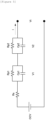
- FIG. 5 is a circuit diagram for explaining a voltage prediction model according to embodiments of the present invention.
- the voltage prediction model according to embodiments of the present invention may be included in the battery behavior prediction model.
- the voltage prediction model may be defined as an RC equivalent circuit including a battery, one or more resistors, and one or more capacitors.
- the voltage prediction model may be implemented as an equivalent circuit model including a battery, a plurality of resistors (Rs, Rp1, Rp2), and a plurality of capacitors (Cp1, Cp2), as shown in FIG. 5 .
- Vt OCV ⁇ I ⁇ Rs ⁇ V 1 ⁇ V 2
- I I ⁇ OCV ⁇ Vt
- Vpol ⁇ SOC 0 SOCend OCV ⁇ Vt dSOC
- the equivalent circuit model shown in FIG. 5 is an example for understanding the present invention, and the voltage prediction model included in the battery behavior prediction model may be implemented differently from the equivalent circuit model in FIG. 5 or be implemented as an electrochemical model.
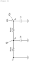
- FIG. 6 is a circuit diagram for explaining a temperature prediction model according to embodiments of the present invention.
- the temperature prediction model according to embodiments of the present invention may be included in the battery behavior prediction model.
- the temperature prediction model may be defined as an RC equivalent circuit including a battery, one or more resistors, and one or more capacitors.
- the temperature prediction model may be implemented as an equivalent circuit model including a battery, a plurality of resistors (Rconv, Rcool), and a plurality of capacitors (Cb, Cc), as shown in FIG. 6 .
- the battery temperature (Tb) may be calculated based on Equations 4 and 5 below.
- Cb ⁇ dTb dt 1 Rconv T ⁇ ⁇ Tb + 1 Rcool Tc ⁇ Tb + Q
- the amount of heat generation in the battery (Q) may be provided from the voltage prediction model in FIG. 5 .
- Cc ⁇ dTc dt 1 Rconv Tc ⁇ Tb + Qh + Qc
- T ⁇ is an outside temperature
- Rconv is the thermal resistance between the outside air and the battery
- Q is the amount of heat generation in the battery
- Cb is the heat capacity of the battery
- Tb battery temperature
- Tc is the coolant temperature
- Rcool is the thermal resistance between the battery and the coolant
- Qh is the amount of heat gain of the coolant
- Qc is the amount of heat loss of the coolant
- Cc is the heat capacity of the coolant
- the equivalent circuit model shown in FIG. 6 is an example for understanding the present invention, and the temperature prediction model included in the battery behavior prediction model may be implemented differently from the equivalent circuit model in FIG. 6 or be implemented as an electrochemical model.
- FIG. 7 is an operational flowchart of a method for deriving an optimal charge map according to embodiments of the present invention.
- the battery charge control apparatus may receive user input information including a charging objective (S510).
- the charging objective may include a charging objective value, including one or more of a target charge amount (SOC_target), a target charge time (t_target), and a target battery temperature at the end of charging (T_end_target), or the charging objective may include charge priority items including one or more of the maximum charge amount, the minimum charge time, and the maximum performance.
- SOC_target target charge amount
- t_target target charge time
- T_end_target target battery temperature at the end of charging
- the battery charge control apparatus may collect battery status information and charger status information (S520).
- the battery charge control apparatus may derive N optimal charge maps that satisfy the charging objective input by a user based on the battery status information and the charger status information (S530).
- the battery charge control apparatus may select, using the predefined battery behavior prediction model, one or more of a first charge map that allows charging in a minimum time (minimum time charge map), a second charge map that allows charging with the maximum charge amount (maximum charge amount charge map), and a third charge map (maximum performance charge map) that satisfies a predefined maximum performance condition and a fourth charge map (maximum lifespan charge map) that satisfies a predefined maximum lifespan condition, among the charge maps that satisfy the charging objective, and determine the selected charge map as the optimal charge map.
- the maximum performance charge map (third charge map) may be determined as a charge map in which the battery temperature after the end of charging is closest to the target battery temperature, or a charge map which shows the battery temperature after the end of charging closest to a predefined optimal temperature value.
- the maximum lifespan charge map (fourth charge map) may be determined as a charge map showing the lowest cumulative amount of polarization values.
- the battery charge control apparatus may determine a first charge map (minimum time charge map), a third charge map (maximum performance charge map), and a fourth charge map (maximum lifespan charge map) as the optimal charge maps (S541).
- the battery charge control apparatus may determine a second charge map (maximum charge amount charge map), a third charge map (maximum performance charge map), and a fourth charge map (maximum lifespan charge map) as the optimal charge maps (S542).
- the battery charge control apparatus may determine a first charge map (minimum time charge map), a second charge map (maximum charge amount charge map), and the fourth charge map (maximum lifespan charge map) as the optimal charge maps (S543).
- the battery charge control apparatus may assign priorities to a plurality of selected optimal charge maps.
- the battery charge control apparatus may define the priorities of the three selected optimal selection maps as in the order of the second charge map (maximum charge amount charge map), the third charge map (maximum performance charge map), and the fourth charge map (maximum lifespan charge map).
- the battery charge control apparatus may define the priorities of the three selected optimal selection maps as in the order of the first charge map (minimum time charge map), the second charge map (maximum charge amount charge map), and the fourth charge map (maximum lifespan charge map).
- the battery charge control apparatus may output information about each of the derived optimal charge maps through a predefined GUI.
- the battery charge control apparatus may output the selected optimal charge maps in order according to predefined priorities.
- the battery charge control apparatus may receive a user selection signal for one of the optimal charge maps from the user interface device.
- the battery charge control apparatus may control the battery to be charged using the optimal charge map corresponding to the received user selection signal.
- the battery charge control apparatus may control the battery to be charged through the optimal charge map defined as the first priority.
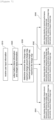
- FIGS. 8 to 10 are examples of screens of a user interface device according to embodiments of the present invention.
- the battery charge control apparatus may determine the minimum time charge map, the maximum performance charge map, and the maximum lifespan charge map as the optimal charge map.
- the battery charge control apparatus may define the priorities of the three selected optimal selection maps in the following order: the minimum time charge map, the maximum performance charge map, and the maximum lifespan charge map.
- the battery charge control apparatus may transmit information about each of the optimal charge maps to the user interface device, and the user interface device may display identification information and charge prediction information of each optimal charge map in order of priority, as shown in FIG. 8 .
- the charge prediction information may be output as is for each item, or at least part of it may be output as a grade.
- the battery temperature value at the time of completion of charging may be classified into one of best, good, average, and bad grades depending on the size, and the classification result may be output on [performance state].
- the accumulated amount of polarization value may be classified into one of the best, good, average, and bad grades depending on the size and the classification result may be output on [lifespan impact].
- the user interface device may receive a selection signal for one of the optimal charge maps from a user through the GUI. Thereafter, the user interface device may transmit the user selection signal to the battery charge control apparatus. If a user selection signal is not input within a predefined time (for example, within 10 seconds), the minimum time charge map defined as first priority may be treated as selected by the user.
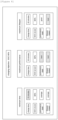
- FIG. 9 is an example of a screen when the charging objective input by a user is the target charge time (20 minutes).
- the battery charge control apparatus may determine the maximum charge amount charge map, the maximum performance charge map, and the maximum lifespan charge map as the optimal charge maps.
- the battery charge control apparatus may define the priorities of the three selected optimal charge maps in the following order: the maximum charge amount charge map, the maximum performance charge map, and the maximum lifespan charge map.
- the user interface device may display identification information and charge prediction information of each of the optimal charge maps according to the priorities.
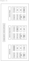
- FIG. 10 is an example of a screen when the charging objective entered by a user is maximum performance among charge priority items.
- the battery charge control apparatus may determine the minimum time charge map, the maximum charge amount charge map, and the maximum lifespan charge map as the optimal charge maps.
- the battery charge control apparatus may define the priorities of the three selected optimal charge maps in the following order: the minimum time charge map, the maximum charge amount charge map, and the maximum lifespan charge map.
- the user interface device may display identification information and charge prediction information of each of the optimal charge maps according to the priorities.
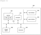
- FIG. 11 is a block diagram of a battery charge control apparatus according to embodiments of the present invention.
- the battery charge control apparatus 300 may include at least one processor 310, a memory 320 that stores at least one instruction executed by the processor, and a transceiver 330 connected to a network to perform communication.
- the at least one instruction may include an instruction to, upon receiving user input information including a charging objective, collect battery state information and charger state information; an instruction to derive a plurality of optimal charge maps that satisfy the charging objective based on the battery state information and the charger state information; an instruction to output information on each of the derived optimal charge maps through a predefined graphical user interface (GUI); and an instruction to, upon receiving a user selection signal for one of the optimal charge maps, control the battery to be charged using an optimal charge map corresponding to the user selection signal.
- GUI graphical user interface
- the charging objective may include at least one charging objective value including one or more of a target charge amount, a target charge time, and a target battery temperature at the point at which charging is completed; or at least one charge priority item including one or more of the maximum charge amount, the minimum charge time, and the maximum performance.
- the instruction to derive the plurality of optimal charge maps may include an instruction to derive optimal charge maps that satisfy the charging objective among a plurality of pre-stored charge maps.
- the instruction to derive the plurality of optimal charge maps may include an instruction to generate charge prediction information for each of the plurality of pre-stored charge maps using a predefined battery behavior prediction model; and an instruction to select N optimal charge maps that satisfy the charging objective based on the generated charge prediction information.
- the instruction to generate charge prediction information may include an instruction to predict one or more of a charge completion time, the charge amount at the charge completion time, the battery temperature at the charge completion time, and an accumulated amount of polarization values, when charging is performed according to the charge map.
- the instruction to derive the plurality of optimal charge maps may include an instruction to select one or more of a first charge map that allows charging in a minimum time, a second charge map that allows charging with a maximum charge amount, a third charge map that satisfies a predefined maximum performance condition, and a fourth charge map that satisfies a predefined maximum lifespan condition, among the charge maps that satisfy the charging objective.
- the instruction to derive the plurality of optimal charge maps may include an instruction to determine one or more of the first charge map, the third charge map, and the fourth charge map as an optimal charge map, in the instance that the charging objective is the target charge amount or the maximum charge amount; an instruction to determine one or more of the second charge map, the third charge map, and fourth charge map as an optimal charge map, in the instance that the charging objective is the target charge time or the minimum charge time; and an instruction to determine one or more of the first charge map, the second charge map, and the fourth charge map as an optimal charge map, in the instance that the charging objective is the target battery temperature at the charge completion time or the maximum performance.
- the instruction to output information through the GUI may include an instruction to output identification information and charge prediction information for each of the N optimal charge maps.
- the instruction to output information through the GUI may include an instruction to output each of the optimal charge maps according to predefined priorities.
- the instruction to control the battery to be charged may include an instruction to control the battery to be charged using the optimal charge map which is defined as the first priority, in the instance that the user selection signal is not received within a predefined period of time.
- the battery charge control apparatus 300 may further include an input interface 340, an output interface 350, a storage device 360, and the like. Respective components included in the battery charge control apparatus 300 may be connected by a bus 370 to communicate with each other.
- the processor 310 may mean a central processing unit (CPU), a graphics processing unit (GPU), or a dedicated processor on which methods according to embodiments of the present invention are performed.
- the memory (or storage device) may include at least one of a volatile storage medium and a non-volatile storage medium.
- the memory may include at least one of read only memory (ROM) and random access memory (RAM).
- the operations of the method according to the embodiments of the present invention may be implemented as a computer-readable program or code on a computer-readable recording medium.
- the computer-readable recording medium includes all types of recording devices in which data readable by a computer system is stored.
- the computer-readable recording medium may be distributed in a network-connected computer system to store and execute computer-readable programs or codes in a distributed manner.
- a block or apparatus corresponds to a method step or feature of a method step.
- aspects described in the context of a method may also represent a feature of a corresponding block or item or a corresponding apparatus.
- Some or all of the method steps may be performed by (or using) a hardware device, such as, for example, a microprocessor, a programmable computer, or an electronic circuit. In some embodiments, one or more of the most important method steps may be performed by such an apparatus.
Landscapes
- Engineering & Computer Science (AREA)
- Power Engineering (AREA)
- Manufacturing & Machinery (AREA)
- Chemical & Material Sciences (AREA)
- Chemical Kinetics & Catalysis (AREA)
- Electrochemistry (AREA)
- General Chemical & Material Sciences (AREA)
- Charge And Discharge Circuits For Batteries Or The Like (AREA)
- Secondary Cells (AREA)
Applications Claiming Priority (2)
| Application Number | Priority Date | Filing Date | Title |
|---|---|---|---|
| KR1020230081593A KR20250000136A (ko) | 2023-06-26 | 2023-06-26 | 배터리 충전 제어 장치 및 방법 |
| PCT/KR2024/000446 WO2025005375A1 (ko) | 2023-06-26 | 2024-01-10 | 배터리 충전 제어 장치 및 방법 |
Publications (2)
| Publication Number | Publication Date |
|---|---|
| EP4550618A1 true EP4550618A1 (de) | 2025-05-07 |
| EP4550618A4 EP4550618A4 (de) | 2026-01-07 |
Family
ID=93938685
Family Applications (1)
| Application Number | Title | Priority Date | Filing Date |
|---|---|---|---|
| EP24832163.0A Pending EP4550618A4 (de) | 2023-06-26 | 2024-01-10 | Verfahren und vorrichtung zur steuerung des batterieladens |
Country Status (6)
| Country | Link |
|---|---|
| US (1) | US20260039135A1 (de) |
| EP (1) | EP4550618A4 (de) |
| JP (1) | JP2025524287A (de) |
| KR (1) | KR20250000136A (de) |
| CN (1) | CN119585975A (de) |
| WO (1) | WO2025005375A1 (de) |
Families Citing this family (1)
| Publication number | Priority date | Publication date | Assignee | Title |
|---|---|---|---|---|
| CN119881667B (zh) * | 2025-03-26 | 2025-07-22 | 深蓝汽车科技有限公司 | 极化电压确定方法、装置、车辆及设备 |
Family Cites Families (15)
| Publication number | Priority date | Publication date | Assignee | Title |
|---|---|---|---|---|
| JP5251117B2 (ja) * | 2007-12-21 | 2013-07-31 | マツダ株式会社 | バッテリ充電方法およびバッテリ充電装置 |
| JP5477965B2 (ja) * | 2010-09-14 | 2014-04-23 | ニチコン株式会社 | 充電制御ユニット |
| JP2012075282A (ja) * | 2010-09-29 | 2012-04-12 | Panasonic Corp | 充電制御装置 |
| US9152202B2 (en) * | 2011-06-16 | 2015-10-06 | Microsoft Technology Licensing, Llc | Mobile device operations with battery optimization |
| US9306412B2 (en) * | 2012-03-30 | 2016-04-05 | Toyota Jidosha Kabushiki Kaisha | Optimum charging for electric-based vehicle |
| JP2014128039A (ja) * | 2012-12-25 | 2014-07-07 | Braveridge Co Ltd | 携帯端末用充電器 |
| US20160111905A1 (en) * | 2014-10-17 | 2016-04-21 | Elwha Llc | Systems and methods for charging energy storage devices |
| US10800413B2 (en) * | 2017-10-16 | 2020-10-13 | Honda Motor Co., Ltd. | System for determining a charging profile for an electric vehicle and method thereof |
| WO2020100288A1 (ja) * | 2018-11-16 | 2020-05-22 | 住友電気工業株式会社 | 充電支援システム、方法、及びコンピュータプログラム |
| JP7554989B2 (ja) * | 2019-11-08 | 2024-09-24 | パナソニックIpマネジメント株式会社 | 充電システム、充電方法、及びプログラム |
| US20230311700A1 (en) * | 2020-07-13 | 2023-10-05 | Hyundai Motor Company | Target power transmission amount changing method and power transmitting apparatus for implementing same |
| KR102772378B1 (ko) | 2020-08-13 | 2025-02-21 | 주식회사 엘지에너지솔루션 | 배터리 관리 시스템, 배터리 관리 방법, 배터리 팩 및 전기 차량 |
| JP7329555B2 (ja) * | 2021-03-19 | 2023-08-18 | 本田技研工業株式会社 | 充電制御装置、移動体、充電制御システム及び充電制御方法 |
| KR20230069786A (ko) * | 2021-11-12 | 2023-05-19 | 삼성전자주식회사 | 배터리의 사용 관리를 위한 배터리 관리 시스템 및 방법 |
| KR102681496B1 (ko) | 2021-11-30 | 2024-07-05 | 한국전자통신연구원 | 영상변환 방법 및 장치 |
-
2023
- 2023-06-26 KR KR1020230081593A patent/KR20250000136A/ko active Pending
-
2024
- 2024-01-10 JP JP2025501510A patent/JP2025524287A/ja active Pending
- 2024-01-10 WO PCT/KR2024/000446 patent/WO2025005375A1/ko not_active Ceased
- 2024-01-10 CN CN202480003436.8A patent/CN119585975A/zh active Pending
- 2024-01-10 US US19/100,993 patent/US20260039135A1/en active Pending
- 2024-01-10 EP EP24832163.0A patent/EP4550618A4/de active Pending
Also Published As
| Publication number | Publication date |
|---|---|
| CN119585975A (zh) | 2025-03-07 |
| US20260039135A1 (en) | 2026-02-05 |
| JP2025524287A (ja) | 2025-07-28 |
| KR20250000136A (ko) | 2025-01-03 |
| EP4550618A4 (de) | 2026-01-07 |
| WO2025005375A1 (ko) | 2025-01-02 |
Similar Documents
| Publication | Publication Date | Title |
|---|---|---|
| US12449485B2 (en) | Battery management apparatus and method | |
| EP4257996B1 (de) | Paralleles batteriesystem und verfahren zur vorhersage der verbleibenden ladezeit davon | |
| US20130293006A1 (en) | Battery balancing system and battery balancing method using the same | |
| JP2009081981A (ja) | 充電状態最適化装置及びこれを具えた組電池システム | |
| US20230361590A1 (en) | Methods and Systems for Enhancing Battery Configuration and Performance | |
| US12571852B2 (en) | Battery life prediction apparatus and method | |
| Darwish et al. | Review of battery management systems | |
| EP4239348B1 (de) | Vorrichtung und verfahren zur schätzung der kapazität einer batteriezelle | |
| EP4550618A1 (de) | Verfahren und vorrichtung zur steuerung des batterieladens | |
| US8918299B2 (en) | System and method for maximizing a battery pack total energy metric | |
| EP4131572A1 (de) | Batteriepack und steuerungsverfahren für batteriepack | |
| KR101748643B1 (ko) | 배터리 팩의 측정 데이터 선별 장치 및 방법 | |
| EP4404417B1 (de) | Batteriesteuerungssystem und verfahren zur verwaltung des batteriezustands | |
| EP4570582A1 (de) | Vorrichtung zur bereitstellung von batteriezustandsinformationen und betriebsverfahren dafür | |
| US20240204272A1 (en) | Battery control system for preventing cell imbalance and operating method thereof | |
| EP4406770B1 (de) | Batterieschutzvorrichtung und -verfahren | |
| KR20250109962A (ko) | 배터리 관리 장치 및 방법 | |
| EP4585941A1 (de) | Elektronische vorrichtung zur erkennung von batterieanomalien und verfahren zum betrieb davon | |
| EP4628916A1 (de) | Batteriediagnosevorrichtung und -verfahren | |
| EP4557569A1 (de) | Energieverwaltungsvorrichtung und energieverwaltungsverfahren | |
| EP4206708A1 (de) | Batterieverwaltungsvorrichtung und -verfahren | |
| KR20260003954A (ko) | 배터리 관리 장치 및 그것의 동작 방법 | |
| EP4697552A1 (de) | Batterieverwaltungsvorrichtung und batterieausgleichsverfahren damit | |
| KR20250122705A (ko) | 배터리 진단 장치 및 이의 동작 방법 | |
| KR20250098036A (ko) | 배터리 진단 장치 및 이의 동작 방법 |
Legal Events
| Date | Code | Title | Description |
|---|---|---|---|
| STAA | Information on the status of an ep patent application or granted ep patent |
Free format text: STATUS: THE INTERNATIONAL PUBLICATION HAS BEEN MADE |
|
| PUAI | Public reference made under article 153(3) epc to a published international application that has entered the european phase |
Free format text: ORIGINAL CODE: 0009012 |
|
| STAA | Information on the status of an ep patent application or granted ep patent |
Free format text: STATUS: REQUEST FOR EXAMINATION WAS MADE |
|
| 17P | Request for examination filed |
Effective date: 20250128 |
|
| AK | Designated contracting states |
Kind code of ref document: A1 Designated state(s): AL AT BE BG CH CY CZ DE DK EE ES FI FR GB GR HR HU IE IS IT LI LT LU LV MC ME MK MT NL NO PL PT RO RS SE SI SK SM TR |
|
| A4 | Supplementary search report drawn up and despatched |
Effective date: 20251204 |
|
| RIC1 | Information provided on ipc code assigned before grant |
Ipc: H02J 7/00 20060101AFI20251128BHEP Ipc: H01M 10/44 20060101ALI20251128BHEP |