EP4239348B1 - Vorrichtung und verfahren zur schätzung der kapazität einer batteriezelle - Google Patents
Vorrichtung und verfahren zur schätzung der kapazität einer batteriezelle Download PDFInfo
- Publication number
- EP4239348B1 EP4239348B1 EP22867531.0A EP22867531A EP4239348B1 EP 4239348 B1 EP4239348 B1 EP 4239348B1 EP 22867531 A EP22867531 A EP 22867531A EP 4239348 B1 EP4239348 B1 EP 4239348B1
- Authority
- EP
- European Patent Office
- Prior art keywords
- battery cell
- capacity
- battery
- module
- curve
- Prior art date
- Legal status (The legal status is an assumption and is not a legal conclusion. Google has not performed a legal analysis and makes no representation as to the accuracy of the status listed.)
- Active
Links
Images

Classifications
-
- G—PHYSICS
- G01—MEASURING; TESTING
- G01R—MEASURING ELECTRIC VARIABLES; MEASURING MAGNETIC VARIABLES
- G01R31/00—Arrangements for testing electric properties; Arrangements for locating electric faults; Arrangements for electrical testing characterised by what is being tested not provided for elsewhere
- G01R31/36—Arrangements for testing, measuring or monitoring the electrical condition of accumulators or electric batteries, e.g. capacity or state of charge [SoC]
- G01R31/396—Acquisition or processing of data for testing or for monitoring individual cells or groups of cells within a battery
-
- G—PHYSICS
- G01—MEASURING; TESTING
- G01R—MEASURING ELECTRIC VARIABLES; MEASURING MAGNETIC VARIABLES
- G01R31/00—Arrangements for testing electric properties; Arrangements for locating electric faults; Arrangements for electrical testing characterised by what is being tested not provided for elsewhere
- G01R31/36—Arrangements for testing, measuring or monitoring the electrical condition of accumulators or electric batteries, e.g. capacity or state of charge [SoC]
- G01R31/3644—Constructional arrangements
- G01R31/3648—Constructional arrangements comprising digital calculation means, e.g. for performing an algorithm
-
- G—PHYSICS
- G01—MEASURING; TESTING
- G01R—MEASURING ELECTRIC VARIABLES; MEASURING MAGNETIC VARIABLES
- G01R31/00—Arrangements for testing electric properties; Arrangements for locating electric faults; Arrangements for electrical testing characterised by what is being tested not provided for elsewhere
- G01R31/36—Arrangements for testing, measuring or monitoring the electrical condition of accumulators or electric batteries, e.g. capacity or state of charge [SoC]
- G01R31/385—Arrangements for measuring battery or accumulator variables
- G01R31/387—Determining ampere-hour charge capacity or SoC
- G01R31/388—Determining ampere-hour charge capacity or SoC involving voltage measurements
-
- G—PHYSICS
- G01—MEASURING; TESTING
- G01R—MEASURING ELECTRIC VARIABLES; MEASURING MAGNETIC VARIABLES
- G01R31/00—Arrangements for testing electric properties; Arrangements for locating electric faults; Arrangements for electrical testing characterised by what is being tested not provided for elsewhere
- G01R31/36—Arrangements for testing, measuring or monitoring the electrical condition of accumulators or electric batteries, e.g. capacity or state of charge [SoC]
- G01R31/392—Determining battery ageing or deterioration, e.g. state of health
-
- H02J7/82—
-
- H02J7/933—
-
- G—PHYSICS
- G01—MEASURING; TESTING
- G01R—MEASURING ELECTRIC VARIABLES; MEASURING MAGNETIC VARIABLES
- G01R31/00—Arrangements for testing electric properties; Arrangements for locating electric faults; Arrangements for electrical testing characterised by what is being tested not provided for elsewhere
- G01R31/36—Arrangements for testing, measuring or monitoring the electrical condition of accumulators or electric batteries, e.g. capacity or state of charge [SoC]
- G01R31/382—Arrangements for monitoring battery or accumulator variables, e.g. SoC
- G01R31/3835—Arrangements for monitoring battery or accumulator variables, e.g. SoC involving only voltage measurements
-
- Y—GENERAL TAGGING OF NEW TECHNOLOGICAL DEVELOPMENTS; GENERAL TAGGING OF CROSS-SECTIONAL TECHNOLOGIES SPANNING OVER SEVERAL SECTIONS OF THE IPC; TECHNICAL SUBJECTS COVERED BY FORMER USPC CROSS-REFERENCE ART COLLECTIONS [XRACs] AND DIGESTS
- Y02—TECHNOLOGIES OR APPLICATIONS FOR MITIGATION OR ADAPTATION AGAINST CLIMATE CHANGE
- Y02E—REDUCTION OF GREENHOUSE GAS [GHG] EMISSIONS, RELATED TO ENERGY GENERATION, TRANSMISSION OR DISTRIBUTION
- Y02E60/00—Enabling technologies; Technologies with a potential or indirect contribution to GHG emissions mitigation
- Y02E60/10—Energy storage using batteries
Definitions
- the present invention relates to an apparatus and method for estimating battery cell capacity, and more particularly, to an apparatus and method for more accurately calculating the capacity of each of a plurality of battery cells included in a module.
- batteries used in an electric vehicle or an energy storage system may be configured as a battery module by connecting a plurality of battery cells to charge or discharge high-output and large-capacity power.
- a battery control technology can be very important in a device or a system that uses a battery as an energy source. As one of control technologies, controlling charging and discharging of the battery based on a remaining battery capacity may be used to increase operation efficiency of a device or a system.
- the capacity of the entire module is determined by a battery cell in which a large amount of deterioration or voltage deviation occurs, and thus, battery capacities for the remaining cells may not be clearly detected.
- an object of the present disclosure is to provide an apparatus for calculating battery cell capacity so that a deterioration state of each battery cell can be accurately diagnosed by estimating the remaining capacities of all cells in a battery module.
- another object of the present disclosure is to provide a method for calculating battery cell capacity.
- an apparatus for estimating battery cell capacity may comprise at least one processor; and a memory for storing at least one instruction executed by the at least one processor, wherein the at least one instruction may include an instruction to derive a discharge curve for each battery cell included in a module including a plurality of battery cells; an instruction to derive a charge curve for each battery cell included in the module; an instruction to calculate an additional dischargeable capacity of a second battery cell based on a pattern of the discharge curve of a first battery cell; an instruction to calculate an additional chargeable capacity of the second battery cell based on a pattern of the charge curve of the first battery cell; and an instruction to calculate a capacity of the second battery cell based on the additional dischargeable capacity and the additional chargeable capacity of the second battery cell.
- the plurality of battery cells may be connected in series and included in the module.
- the first battery cell may be a battery cell in which deterioration has progressed the most among a plurality of battery cells in the module.
- the instruction to calculate an additional dischargeable capacity of a second battery cell may include an instruction to extend the discharge curve of the second battery cell to a voltage at which the first battery cell is discharged to the maximum based on a pattern of the discharge curve of the first battery cell, wherein the extended part of the discharge curve of the second battery cell is derived by shifting the discharge curve of the first battery cell on the time axis.
- the instruction to calculate an additional chargeable capacity of the second battery cell may include an instruction to extend the charge curve of the second battery cell to a voltage at which the first battery cell is charged to the maximum based on a pattern of the charge curve of the first battery cell, wherein the extended part of the charge curve of the first battery cell is derived by shifting the charge curve of the first battery cell on the time axis.
- the capacity of the second battery cell may be calculated based on the discharge capacity of the module, the additional dischargeable capacity of the second battery cell, the additional chargeable capacity of the second battery cell, and a charge-discharge efficiency, the charge-discharge efficiency being obtained by dividing a module discharge capacity by a module charge capacity.
- the second battery cell may be any one of the remaining cells except for the first battery cell among all the battery cells in the module.
- a method for estimating battery cell capacity may comprise deriving a discharge curve for each battery cell included in a module including a plurality of battery cells; deriving a charge curve for each battery cell included in the module; calculating an additional dischargeable capacity of a second battery cell based on a pattern of the discharge curve of a first battery cell; calculating an additional chargeable capacity of the second battery cell based on a pattern of the charge curve of the first battery cell; and calculating a capacity of the second battery cell based on the additional dischargeable capacity and the additional chargeable capacity of the second battery cell.
- the plurality of battery cells may be connected in series and included in the module.
- the first battery cell may be a battery cell in which deterioration has progressed the most among a plurality of battery cells in the module.
- the calculating an additional dischargeable capacity of a second battery cell may include extending the discharge curve of the second battery cell to a voltage at which the first battery cell is discharged to the maximum based on a pattern of the discharge curve of the first battery cell, wherein the extended part of the discharge curve of the second battery cell is derived by shifting the discharge curve of the first battery cell on the time axis.
- the calculating an additional chargeable capacity of the second battery cell may include extending the charge curve of the second battery cell to a voltage at which the first battery cell is charged to the maximum based on a pattern of the charge curve of the first battery cell, wherein the extended part of the charge curve of the first battery cell is derived by shifting the charge curve of the first battery cell on the time axis.
- the calculating the capacity of the second battery cell may include calculating the capacity of the second battery cell based on the discharge capacity of the module, the additional dischargeable capacity of the second battery cell, the additional chargeable capacity of the second battery cell, and a charge-discharge efficiency, the charge-discharge efficiency being obtained by dividing a module discharge capacity by a module charge capacity.
- the capacity of the second battery cell may be calculated based on the discharge capacity of the module, the additional dischargeable capacity of the second battery cell, the additional chargeable capacity of the second battery cell, and a charge-discharge efficiency.
- the second battery cell may be any one of the remaining cells except for the first battery cell among all the battery cells in the module.
- first, second, A, B, and the like may be used herein to describe various elements, these elements should not be limited by these terms. These terms are only used to distinguish one element from another. For example, a first element could be termed a second element, and, similarly, a second element could be termed a first element, without departing from the scope of the present invention.
- the term "and/or" includes combinations of a plurality of associated listed items or any of the plurality of associated listed items.
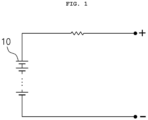
- FIG. 1 is a block diagram of a typical battery module.
- a battery module 10 may typically include a plurality of battery cells connected in series with each other. In FIG. 1 , N battery cells are connected in series, thereby constituting a battery module.
- a battery cell is a minimum unit of a battery that serves to store energy.
- a series/parallel combination of battery cells may constitute a battery module, and a plurality of battery modules may constitute a battery rack or a battery pack.
- a battery pack may include not only a plurality of battery cells connected in series, but also various components for charging and discharging the battery pack, such as a bus bar, a cable, a relay, and a control circuit.
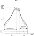
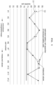
- FIG. 2 is a graph illustrating voltage changes during charging/discharging operations of a plurality of battery cells connected in series.
- Each curve in FIG. 2 shows a change of measured voltages of each battery cell over time.
- a first time section 21 represents a section in which charging occurs and a second time section 22 represents a section in which discharging occurs.
- the charge upper limit voltage is a maximum voltage for safely charging the battery cell and may be preset.
- the discharge lower limit voltage is a minimum voltage for safely discharging the battery cell and may be preset.
- a dotted curve is a voltage behavior of a battery cell in which deterioration occurs the most.
- the the most deteriorated battery cell reaches the upper limit of charge voltage first during charging and at this moment, charging operations for all the battery cells in the module are stopped.
- discharging discharging of a battery cell that has undergone the most degradation proceeds the fastest, so that the voltage of the battery cell reaches the lower limit of discharge first.
- the discharging operation for the most deteriorated battery cell but also the discharging operations of the other battery cells are stopped.
- the capacity of the entire module is determined by the capacity of the battery cell in which deterioration has progressed the most.
- the capacity of the module is the same as the capacity of one battery cell that has deteriorated the most among all battery cells in the module.
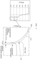
- FIG. 3 illustrates a concept of deriving an additionally dischargeable capacity of each battery cell from a behavior graph of a lowest discharge capacity cell according to embodiments of the present invention.
- the curve 300 in FIG. 3 shows a voltage behavior of the lowest discharge capacity cell, mearsured over time during discharging.
- the cell with the lowest discharge capacity may be a cell which has undergone degradation the most in the module.
- the portion corresponding to the line above the point Pd shows a discharge behavior of one of the battery cells in the module except for the lowest discharge capacity cell.
- a virtual curve (indicated by a dotted line below Pd in FIG. 3 ) for a first battery cell which is one of the battey cells in the module may be generated.
- the virtual curve may extend from a point where discharging stops in the actual discharge line of the first battery cell, that is, point Pd in FIG. 3 , in a direction in which the voltage is getting lowered.
- the virtual discharge curve for the first battery cell may be set to be the same as the pattern of the discharge curve 300 of the cell with the lowest discharge capacity.
- the virtual discharge curve for the first battery cell may extend in a direction in which the voltage of the battery cell decreases from the point Pd as time elapses, and followes a line in which the discharge curve 300 of the lowest discharge capacity cell is shifted on the time axis.
- a virtual discharge curve for the first battery cell indicated by a dotted line is represented as an extrapolated voltage behavior.
- an additionally dischargable capacity of first battery cell may be a dischargable amount corresponding to an amount of time to which the virtual discharge curve for the first battery cell is shifted on the time axis from the discharge curve 300 of the lowest discharge capacity cell.
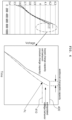
- FIG. 4 illustrates a concept of deriving an additionally chargeable capacity of each battery cell from a behavior graph of the lowest charge capacity cell according to embodiments of the present invention.
- the curve 400 in FIG. 4 shows the voltage behavior of the lowest charge capacity cell, measured over time during charging.
- the lowest charge capacity cell may be a cell that has undergone the most degradation in the module.
- a portion corresponding to a line below the point Pc indicates a charging behavior of one of the battery cells in the module except for the lowest charge capacity cell.
- a virtual curve (indicated by a dotted line above Pc in FIG. 4 ) for a first battery cell which is one of the battey cells in the module may be generated.
- the virtual curve may extend from a point where charging stops in the actual charge curve of the first battery cell, that is, the point Pc in FIG. 4 in a direction in which the voltage rises.
- the virtual charge curve for the first battery cell may be set to be the same as the pattern of the charge curve 400 of the lowest charge capacity cell.
- the virtual charge curve for the first battery cell may extend in a direction in which the voltage of the battery cell increases from the point Pc as time elapses and followes a curve in which the charge curve 400 of the lowest charge capacity cell is shifted on the time axis.
- a virtual charge curve for the first battery cell indicated by a dotted line is represented as an extrapolated voltage behavior.
- an additionally chargeable capacity of first battery cell may be a chargable amount corresponding to an amount of time to which the virtual charge curve for the first battery cell is shifted on the time axis from the curve 400 of the lowest charge capacity cell.
- each battery cell may be calculated based on the additional dischargeable capacity and the additional chargeable capacity which are derived through the methods described with reference to FIGs. 3 and 4 .
- the individual capacity of each cell may indicate an amount of electricity (Ah) that can be output when it is assumed that the cell is charged to the upper limit voltage and discharged to the lower limit voltage.
- the charge-discharge efficiency may be defined as a value obtained by dividing a module discharge capacity by a module charge capacity.
- FIG. 5 is a graph illustrating a battery cell capacity estimation result according to embodiments of the present invention in comparison with an actually measured value.
- line 51 includes capacities of individual battery cells calculated as described in the above embodiments using the charge/discharge curve of each battery cell in a module including 12 battery cells connected in series.
- graph 53 shows values obtained by individually measuring the capacities of respective battery cells by disassembling the module.
- Line 51 and line 53 show 1% of difference on average, up to 3% maximum. Thus, there is no significant difference between the actually measured capacity of the battery cell and the estimated capacity of the battery cell according to the present invention. Accordingly, an actual deterioration state of a battery cell can be accurately determined without disassembling a module and measuring each disassembled battery cell, according to a method for calculating the battery cell capacity suggested by the present invention.
- FIG. 6 is a block diagram of an apparatus for estimating battery cell capacity according to embodiments of the present invention.
- the apparatus for calculating a battery cell capacity may include a memory 100, at least one processor 200, a transceiver 300, and a storage device 600.
- Each of the components 100, 200, 300, and 600 included in the apparatus for calculating the capacity of a battery cell may be connected by a bus 700 to perform communication with each other.
- the apparatus for calculating battery cell capacity according to the present invention may be implemented as a battery management system (BMS) or included in the battery management system which may be a part of a battery system or a separate device.
- BMS battery management system
- the memory 100 and the storage device 600 may be configured as at least one of a volatile storage medium and a non-volatile storage medium.
- the memory 100 and the storage device 600 may include at least one of a read only memory (ROM) and a random access memory (RAM).
- ROM read only memory
- RAM random access memory
- the memory 100 may store at least one instruction or command executed by the processor 200.
- the processor 200 may comprise a central processing unit (CPU), a graphics processing unit (GPU), or a dedicated processor on which methods according to embodiments of the present invention are performed.
- the processor 200 may execute at least one program command or instruction stored in the memory 100.
- the at least one instruction may include an instruction to derive a discharge curve for each battery cell included in a module including a plurality of battery cells; an instruction to derive a charge curve for each battery cell included in the module; an instruction to calculate an additional dischargeable capacity of a second battery cell based on a pattern of the discharge curve of a first battery cell; an instruction to calculate an additional chargeable capacity of the second battery cell based on the transition of the charge curve of the first battery cell; and an instruction to calculate a capacity of the second battery cell based on the additional dischargeable capacity and the additional chargeable capacity of the second battery cell.
- the plurality of battery cells may be connected in series and included in the module.
- the first battery cell may be a battery cell in which deterioration has progressed the most among a plurality of battery cells in the module.
- the instruction to calculate an additional dischargeable capacity of a second battery cell may include an instruction to extend the discharge curve of the second battery cell to a voltage at which the first battery cell is discharged to the maximum based on a pattern of the discharge curve of the first battery cell, wherein the extended part of the discharge curve of the second battery cell is derived by shifting the discharge curve of the first battery cell on the time axis.
- the instruction to calculate an additional chargeable capacity of the second battery cell may include an instruction to extend the charge curve of the second battery cell to a voltage at which the first battery cell is charged to the maximum based on a pattern of the charge curve of the first battery cell, wherein the extended part of the charge curve of the first battery cell is derived by shifting the charge curve of the first battery cell on the time axis.
- the capacity of the second battery cell may be calculated based on the discharge capacity of the module, the additional dischargeable capacity of the second battery cell, the additional chargeable capacity of the second battery cell, and a charge-discharge efficiency.
- the memory 100 or the storage device 600 may store information on the charge curves and the discharge curves of respective battery cells and the battery module calculated by the processor.
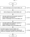
- FIG. 7 is a flowchart of a method for estimating battery cell capacity according to embodiments of the present invention.
- the method for calculating battery cell capacity illustrated in FIG. 7 relates to a method for calculating capacity of each battery cell in a battery module including a plurality of battery cells, and may be performed by an apparatus for calculating battery cell capacity.
- the apparatus for calculating battery cell capacity may be a battery management system (BMS).
- BMS battery management system
- the plurality of battery cells may be connected in series and included in the battery module.
- the apparatus for calculating battery cell capacity may derive a discharge curve of each battery cell included in the battery module (S711).
- the apparatus for calculating battery cell capacity may also derive a charge curve of each battery cell included in the battery module (S712).
- an additional dischargeable capacity of a second battery cell may be calculated according to a transition pattern of the discharge curve of a first battery cell (S721). More specifically, the discharge curve of the second battery cell may be extended to a voltage at which the first battery cell is discharged to the maximum based on a pattern of the discharge curve of the first battery cell, wherein the extended part of the discharge curve of the second battery cell is derived by shifting the discharge curve of the first battery cell on the time axis.
- the first battery cell may be a battery cell in which deterioration has progressed the most among a plurality of battery cells in the module.
- an additional chargeable capacity of the second battery cell may be calculated according to a transition pattern of the charge curve of the first battery cell (S722). More specifically, the charging curve of the second battery cell may be extended to a voltage at which the first battery cell is charged to the maximum based on a pattern of the charge curve of the first battery cell, wherein the extended part of the charge curve of the first battery cell is derived by shifting the charge curve of the first battery cell on the time axis.
- steps 711, 712, 721, and 722 are illustrated in order, but steps 711 and 712 may be performed simultaneously or the order may be reversed. This applies to steps 721 and 722 the same. However, step 721 should be performed after step 711 and step 722 should be performed after step 712.
- the capacity of the second battery cell may be calculated based on the calculated additional dischargeable capacity and additional chargeable capacity of the second battery cell (S730). More specifically, the capacity of the second battery cell may be calculated based on the discharge capacity of the module, the derived additional dischargeable capacity of the second battery cell, the additional chargeable capacity of the second battery cell, and charge-discharge efficiency.
- the charge-discharge efficiency may be defined as a value obtained by dividing a module discharge capacity by a module charge capacity.
- a block or apparatus corresponds to a method step or feature of a method step.
- aspects described in the context of a method may also represent a feature of a corresponding block or item or a corresponding apparatus.
- Some or all of the method steps may be performed by (or using) a hardware device, such as, for example, a microprocessor, a programmable computer, or an electronic circuit. In some embodiments, one or more of the most important method steps may be performed by such an apparatus.
Landscapes
- Physics & Mathematics (AREA)
- General Physics & Mathematics (AREA)
- Secondary Cells (AREA)
- Charge And Discharge Circuits For Batteries Or The Like (AREA)
- Tests Of Electric Status Of Batteries (AREA)
- Engineering & Computer Science (AREA)
- Power Engineering (AREA)
Claims (14)
- Vorrichtung zum Schätzen einer Batteriezellen-Kapazität, umfassend:wenigstens einen Prozessor (200); undeinen Speicher (100) zum Speichern von wenigstens einer Anweisung, welche von dem wenigstens einen Prozessor ausgeführt wird,wobei die wenigstens eine Anweisung umfasst:eine Anweisung zum Ableiten einer Entladekurve für jede Batteriezelle, welche in einem Modul (10) umfasst ist, welches eine Mehrzahl von Batteriezellen umfasst;eine Anweisung zum Berechnen einer zusätzlichen entladbaren Kapazität einer zweiten Batteriezelle auf Grundlage eines Musters der Entladekurve einer ersten Batteriezelle;dadurch gekennzeichnet, dass die wenigstens eine Anweisung ferner umfasst:eine Anweisung zum Ableiten einer Ladekurve für jede Batteriezelle, welche in dem Modul umfasst ist;eine Anweisung zum Berechnen einer zusätzlichen ladbaren Kapazität der zweiten Batteriezelle auf Grundlage eines Musters der Ladekurve der ersten Batteriezelle;
undeine Anweisung zum Berechnen einer Kapazität der zweiten Batteriezelle auf Grundlage der zusätzlichen entladbaren Kapazität und der zusätzlichen ladbaren Kapazität der zweiten Batteriezelle. - Vorrichtung nach Anspruch 1, wobei die Mehrzahl von Batteriezellen in Reihe verbunden und in dem Modul umfasst sind.
- Vorrichtung nach Anspruch 1, wobei die erste Batteriezelle eine Batteriezelle ist, in welcher unter einer Mehrzahl von Batteriezellen in dem Modul eine Verschlechterung am meisten fortgeschritten ist.
- Vorrichtung nach Anspruch 1, wobei die Anweisung zum Berechnen einer zusätzlichen entladbaren Kapazität einer zweiten Batteriezelle eine Anweisung umfasst zum:
Ausdehnen der Entladekurve der zweiten Batteriezelle zu einer Spannung, bei welcher die erste Batteriezelle entladen wird, zu dem Maximum auf Grundlage eines Musters der Entladekurve der ersten Batteriezelle, wobei der ausgedehnte Teil der Entladekurve der zweiten Batteriezelle durch Verschieben der Entladekurve der ersten Batteriezelle auf der Zeitachse abgeleitet wird. - Vorrichtung nach Anspruch 1, wobei die Anweisung zum Berechnen einer zusätzlichen ladbaren Kapazität der zweiten Batteriezelle eine Anweisung umfasst zum:
Ausdehnen der Ladekurve der zweiten Batteriezelle von einer Spannung, bei welcher die erste Batteriezelle geladen wird, zu dem Maximum auf Grundlage eines Musters der Ladekurve der ersten Batteriezelle, wobei der ausgedehnte Teil der Ladekurve der ersten Batteriezelle durch Verschieben der Ladekurve der ersten Batteriezelle auf der Zeitachse abgeleitet wird. - Vorrichtung nach Anspruch 1, wobei die Kapazität der zweiten Batteriezelle auf Grundlage der Entladekapazität des Moduls, der zusätzlichen entladbaren Kapazität der zweiten Batteriezelle, der zusätzlichen ladbaren Kapazität der zweiten Batteriezelle und einer Lade-Entlade-Effizienz berechnet wird, wobei die Lade-Entlade-Effizienz durch Teilen einer Modul-Entladekapazität durch eine Modul-Lade-Kapazität erhalten wird.
- Vorrichtung nach Anspruch 1, wobei die zweite Batteriezelle eine beliebige aus den verbleibenden Zellen außer der ersten Batteriezelle unter allen der Batteriezellen in dem Modul ist.
- Verfahren zum Schätzen einer Batteriezellen-Kapazität, umfassend:Ableiten (S711) einer Entladekurve für jede Batteriezelle, welche in einem Modul umfasst ist, welches eine Mehrzahl von Batteriezellen umfasst;Berechnen (S721) einer zusätzlichen entladbaren Kapazität einer zweiten Batteriezelle auf Grundlage eines Musters der Entladekurve einer ersten Batteriezelle;dadurch gekennzeichnet, dass das Verfahren ferner umfasst:Ableiten (S712) einer Ladekurve für jede Batteriezelle, welche in dem Modul umfasst ist;Berechnen (S722) einer zusätzlichen ladbaren Kapazität der zweiten Batteriezelle auf Grundlage eines Musters der Ladekurve der ersten Batteriezelle; undBerechnen (S730) einer Kapazität der zweiten Batteriezelle auf Grundlage der zusätzlichen entladbaren Kapazität und der zusätzlichen ladbaren Kapazität der zweiten Batteriezelle.
- Verfahren nach Anspruch 8, wobei die Mehrzahl von Batteriezellen in Reihe verbunden und in dem Modul umfasst sind.
- Verfahren nach Anspruch 8, wobei die erste Batteriezelle eine Batteriezelle ist, in welcher unter einer Mehrzahl von Batteriezellen in dem Modul eine Verschlechterung am meisten fortgeschritten ist.
- Verfahren nach Anspruch 8, wobei das Berechnen einer zusätzlichen entladbaren Kapazität einer zweiten Batteriezelle umfasst:
Ausdehnen der Entladekurve der zweiten Batteriezelle zu einer Spannung, bei welcher die erste Batteriezelle entladen wird, zu dem Maximum auf Grundlage eines Musters der Entladekurve der ersten Batteriezelle, wobei der ausgedehnte Teil der Entladekurve der zweiten Batteriezelle durch Verschieben der Entladekurve der ersten Batteriezelle auf der Zeitachse abgeleitet wird. - Verfahren nach Anspruch 8, wobei das Berechnen einer zusätzlichen ladbaren Kapazität der zweiten Batteriezelle eine Anweisung umfasst:
Ausdehnen der Ladekurve der zweiten Batteriezelle zu einer Spannung, bei welcher die erste Batteriezelle geladen wird, zu dem Maximum auf Grundlage eines Musters der Ladekurve der ersten Batteriezelle, wobei der ausgedehnte Teil der Ladekurve der ersten Batteriezelle durch Verschieben der Ladekurve der ersten Batteriezelle auf der Zeitachse abgeleitet wird. - Verfahren nach Anspruch 8, wobei die Kapazität der zweiten Batteriezelle auf Grundlage der Entladekapazität des Moduls, der zusätzlichen entladbaren Kapazität der zweiten Batteriezelle, der zusätzlichen ladbaren Kapazität der zweiten Batteriezelle und einer Lade-Entlade-Effizienz berechnet wird, wobei die Lade-Entlade-Effizienz durch Teilen einer Modul-Entladekapazität durch eine Modul-Lade-Kapazität erhalten wird.
- Verfahren nach Anspruch 8, wobei die zweite Batteriezelle eine beliebige der verbleibenden Zellen außer der ersten Batteriezelle unter allen der Batteriezellen in dem Modul ist.
Applications Claiming Priority (2)
| Application Number | Priority Date | Filing Date | Title |
|---|---|---|---|
| KR1020210120059A KR102889264B1 (ko) | 2021-09-09 | 2021-09-09 | 배터리 셀의 용량 산출 장치 및 방법 |
| PCT/KR2022/010048 WO2023038262A1 (ko) | 2021-09-09 | 2022-07-11 | 배터리 셀의 용량 산출 장치 및 방법 |
Publications (3)
| Publication Number | Publication Date |
|---|---|
| EP4239348A1 EP4239348A1 (de) | 2023-09-06 |
| EP4239348A4 EP4239348A4 (de) | 2024-06-19 |
| EP4239348B1 true EP4239348B1 (de) | 2025-04-02 |
Family
ID=85506609
Family Applications (1)
| Application Number | Title | Priority Date | Filing Date |
|---|---|---|---|
| EP22867531.0A Active EP4239348B1 (de) | 2021-09-09 | 2022-07-11 | Vorrichtung und verfahren zur schätzung der kapazität einer batteriezelle |
Country Status (8)
| Country | Link |
|---|---|
| US (1) | US20240094306A1 (de) |
| EP (1) | EP4239348B1 (de) |
| JP (1) | JP7517760B2 (de) |
| KR (1) | KR102889264B1 (de) |
| CN (1) | CN116569053A (de) |
| ES (1) | ES3023850T3 (de) |
| HU (1) | HUE071110T2 (de) |
| WO (1) | WO2023038262A1 (de) |
Families Citing this family (3)
| Publication number | Priority date | Publication date | Assignee | Title |
|---|---|---|---|---|
| KR102868621B1 (ko) * | 2023-05-23 | 2025-10-13 | 한국에너지기술연구원 | 전지 수명을 예측하기 위한 전지 수명 예측 방법 |
| KR102877207B1 (ko) * | 2023-06-15 | 2025-10-29 | 한국철도기술연구원 | 리튬 배터리 특성 추정 장치 및 방법 |
| US20260036643A1 (en) * | 2024-07-31 | 2026-02-05 | Samsung Sdi Co., Ltd. | Battery cell replacement detection apparatus and method |
Family Cites Families (26)
| Publication number | Priority date | Publication date | Assignee | Title |
|---|---|---|---|---|
| US6057670A (en) * | 1998-11-04 | 2000-05-02 | Saft America, Inc. | Smart connector for rechargeable battery |
| CA2636664C (en) * | 2001-07-05 | 2012-04-10 | Research In Motion Limited | System and method for battery capacity reporting |
| US8374807B2 (en) * | 2008-11-13 | 2013-02-12 | Lockheed Martin Corporation | Method and apparatus that detects state of charge (SOC) of a battery |
| US9146280B2 (en) * | 2011-10-26 | 2015-09-29 | Industrial Technology Research Institute | Method and system for estimating a capacity of a battery |
| JP5880162B2 (ja) * | 2012-03-12 | 2016-03-08 | 三菱自動車工業株式会社 | 組電池の充放電制御装置 |
| US9651624B2 (en) * | 2012-12-17 | 2017-05-16 | Qualcomm Incorporated | Systems and methods for state of charge estimation |
| CN103399278B (zh) * | 2013-07-31 | 2016-03-23 | 清华大学 | 电池单体的容量和荷电状态的估计方法 |
| US20150276885A1 (en) * | 2014-03-25 | 2015-10-01 | Stmicroelectronics International N.V. | Method of Computing State of Charge and Battery State of Charge Monitor |
| EP2990818B1 (de) * | 2014-09-01 | 2019-11-27 | Yokogawa Electric Corporation | Sekundärbatteriekapazitätsmesssystem und sekundärbatteriekapazitätsmessverfahren |
| KR102577581B1 (ko) * | 2014-12-26 | 2023-09-12 | 삼성전자주식회사 | 배터리의 성능 상태를 추정하는 방법 및 장치 |
| JP2017220293A (ja) * | 2016-06-03 | 2017-12-14 | 大和製罐株式会社 | 電池の充放電曲線推定装置及び、その充放電曲線推定方法 |
| FR3054669B1 (fr) * | 2016-07-29 | 2018-07-27 | Commissariat A L'energie Atomique Et Aux Energies Alternatives | Procede de determination de l'etat de sante des cellules d'une batterie |
| JP7116068B2 (ja) * | 2017-01-25 | 2022-08-09 | ユーキャップ パワー インコーポレイテッド | キャパシタモジュールバランシング及びメンテナンスのためのシステム及び方法 |
| JP6958427B2 (ja) * | 2018-02-27 | 2021-11-02 | トヨタ自動車株式会社 | 二次電池システム |
| CN110320477B (zh) * | 2018-03-30 | 2021-09-03 | 比亚迪股份有限公司 | 动力电池组的soc计算方法、装置和电动汽车 |
| CN109164398B (zh) * | 2018-08-03 | 2019-10-11 | 北京交通大学 | 一种锂离子电池组中单体电池容量估算方法 |
| FR3090115B1 (fr) * | 2018-12-12 | 2020-12-25 | Commissariat Energie Atomique | Procédé de détermination de l'état de santé des cellules d'une batterie |
| FR3090118B1 (fr) * | 2018-12-12 | 2020-12-25 | Commissariat Energie Atomique | Procédé de détermination de l'état de santé des cellules d'une batterie |
| KR102714079B1 (ko) * | 2019-09-11 | 2024-10-04 | 주식회사 엘지에너지솔루션 | 배터리 관리 장치 및 방법 |
| KR102784187B1 (ko) | 2019-09-11 | 2025-03-21 | 삼성전자주식회사 | 배터리 이상 상태를 진단하기 위한 방법, 이를 위한 전자 장치 및 저장 매체 |
| KR102824059B1 (ko) * | 2019-11-26 | 2025-06-20 | 주식회사 엘지에너지솔루션 | 배터리 상태 진단 장치 및 방법 |
| KR102216938B1 (ko) * | 2020-05-26 | 2021-02-18 | 주식회사 나산전기산업 | Bms시스템에 적용되는 배터리의 충방전 특성을 사용한 배터리 수명 예측 시스템 |
| CN111781529B (zh) * | 2020-07-14 | 2023-06-27 | 上海理工大学 | 基于电动汽车云端数据的电池组单体容量估计方法和装置 |
| CN112816893B (zh) * | 2021-01-04 | 2022-11-01 | 上海理工大学 | 一种基于电池组单体剩余充电电量快速估计电池组容量方法 |
| US20220368150A1 (en) * | 2021-04-27 | 2022-11-17 | China Energy Investment Corporation Limited | Voltage gradient-biased controller, system and method for controlling discharge of heterogeneous battery packs |
| CN113253140B (zh) * | 2021-07-16 | 2021-09-28 | 杭州科工电子科技有限公司 | 电池健康状态在线估算方法 |
-
2021
- 2021-09-09 KR KR1020210120059A patent/KR102889264B1/ko active Active
-
2022
- 2022-07-11 WO PCT/KR2022/010048 patent/WO2023038262A1/ko not_active Ceased
- 2022-07-11 EP EP22867531.0A patent/EP4239348B1/de active Active
- 2022-07-11 US US18/038,938 patent/US20240094306A1/en active Pending
- 2022-07-11 ES ES22867531T patent/ES3023850T3/es active Active
- 2022-07-11 HU HUE22867531A patent/HUE071110T2/hu unknown
- 2022-07-11 CN CN202280007767.XA patent/CN116569053A/zh active Pending
- 2022-07-11 JP JP2023530731A patent/JP7517760B2/ja active Active
Also Published As
| Publication number | Publication date |
|---|---|
| JP7517760B2 (ja) | 2024-07-17 |
| WO2023038262A1 (ko) | 2023-03-16 |
| JP2023551202A (ja) | 2023-12-07 |
| KR20230037130A (ko) | 2023-03-16 |
| EP4239348A1 (de) | 2023-09-06 |
| HUE071110T2 (hu) | 2025-08-28 |
| ES3023850T3 (en) | 2025-06-03 |
| EP4239348A4 (de) | 2024-06-19 |
| CN116569053A (zh) | 2023-08-08 |
| KR102889264B1 (ko) | 2025-11-20 |
| US20240094306A1 (en) | 2024-03-21 |
Similar Documents
| Publication | Publication Date | Title |
|---|---|---|
| US12174262B2 (en) | Battery management apparatus | |
| US11824395B2 (en) | Battery management apparatus | |
| EP4239348B1 (de) | Vorrichtung und verfahren zur schätzung der kapazität einer batteriezelle | |
| US11614495B2 (en) | Battery state estimating apparatus | |
| US12449485B2 (en) | Battery management apparatus and method | |
| US20230361590A1 (en) | Methods and Systems for Enhancing Battery Configuration and Performance | |
| US10011185B2 (en) | Method for battery management and battery management system | |
| US20240030710A1 (en) | Power distribution method and energy storage system using same | |
| CN115173511A (zh) | 一种动力电池均衡方法及装置 | |
| KR20240016135A (ko) | 배터리 관리 장치 및 그것의 동작 방법 | |
| EP4404417B1 (de) | Batteriesteuerungssystem und verfahren zur verwaltung des batteriezustands | |
| EP4379994B1 (de) | Batterievorrichtung mit einem batterieverwaltungssystem | |
| KR20250058902A (ko) | 밸런싱을 위한 배터리 관리 장치 및 방법 | |
| KR102899750B1 (ko) | 배터리 건전성 관리 및 효율 운전 방법 및 장치 | |
| JP7749861B2 (ja) | 電池システム及びその電池バランシング方法 | |
| US20250239866A1 (en) | Battery System for Sequential Charging of Batteries and Control Method Thereof | |
| CN121511540A (zh) | 电池管理装置及其电池平衡方法 | |
| KR20240170064A (ko) | 배터리 충전 제어 장치 및 방법 | |
| KR20240174631A (ko) | 배터리 충전 제어 장치 및 방법 | |
| KR20250124645A (ko) | 차량 제어 장치 및 그 방법 | |
| CN119482863A (zh) | 多电池充电方法、装置、用电设备、电子设备和存储介质 | |
| CN117962693A (zh) | 电池被动均衡控制方法、装置、设备及可读存储介质 |
Legal Events
| Date | Code | Title | Description |
|---|---|---|---|
| STAA | Information on the status of an ep patent application or granted ep patent |
Free format text: STATUS: THE INTERNATIONAL PUBLICATION HAS BEEN MADE |
|
| PUAI | Public reference made under article 153(3) epc to a published international application that has entered the european phase |
Free format text: ORIGINAL CODE: 0009012 |
|
| STAA | Information on the status of an ep patent application or granted ep patent |
Free format text: STATUS: REQUEST FOR EXAMINATION WAS MADE |
|
| 17P | Request for examination filed |
Effective date: 20230602 |
|
| AK | Designated contracting states |
Kind code of ref document: A1 Designated state(s): AL AT BE BG CH CY CZ DE DK EE ES FI FR GB GR HR HU IE IS IT LI LT LU LV MC MK MT NL NO PL PT RO RS SE SI SK SM TR |
|
| A4 | Supplementary search report drawn up and despatched |
Effective date: 20240523 |
|
| RIC1 | Information provided on ipc code assigned before grant |
Ipc: G01R 31/388 20190101ALI20240516BHEP Ipc: G01R 31/396 20190101ALI20240516BHEP Ipc: G01R 31/392 20190101ALI20240516BHEP Ipc: G01R 31/382 20190101ALI20240516BHEP Ipc: G01R 31/367 20190101AFI20240516BHEP |
|
| GRAP | Despatch of communication of intention to grant a patent |
Free format text: ORIGINAL CODE: EPIDOSNIGR1 |
|
| STAA | Information on the status of an ep patent application or granted ep patent |
Free format text: STATUS: GRANT OF PATENT IS INTENDED |
|
| RIC1 | Information provided on ipc code assigned before grant |
Ipc: G01R 31/388 20190101ALI20241008BHEP Ipc: G01R 31/396 20190101ALI20241008BHEP Ipc: G01R 31/392 20190101ALI20241008BHEP Ipc: G01R 31/382 20190101ALI20241008BHEP Ipc: G01R 31/367 20190101AFI20241008BHEP |
|
| DAV | Request for validation of the european patent (deleted) | ||
| DAX | Request for extension of the european patent (deleted) | ||
| INTG | Intention to grant announced |
Effective date: 20241025 |
|
| P01 | Opt-out of the competence of the unified patent court (upc) registered |
Free format text: CASE NUMBER: APP_59675/2024 Effective date: 20241104 |
|
| GRAS | Grant fee paid |
Free format text: ORIGINAL CODE: EPIDOSNIGR3 |
|
| GRAA | (expected) grant |
Free format text: ORIGINAL CODE: 0009210 |
|
| STAA | Information on the status of an ep patent application or granted ep patent |
Free format text: STATUS: THE PATENT HAS BEEN GRANTED |
|
| AK | Designated contracting states |
Kind code of ref document: B1 Designated state(s): AL AT BE BG CH CY CZ DE DK EE ES FI FR GB GR HR HU IE IS IT LI LT LU LV MC MK MT NL NO PL PT RO RS SE SI SK SM TR |
|
| REG | Reference to a national code |
Ref country code: GB Ref legal event code: FG4D |
|
| REG | Reference to a national code |
Ref country code: CH Ref legal event code: EP |
|
| REG | Reference to a national code |
Ref country code: IE Ref legal event code: FG4D |
|
| REG | Reference to a national code |
Ref country code: DE Ref legal event code: R096 Ref document number: 602022012713 Country of ref document: DE |
|
| REG | Reference to a national code |
Ref country code: ES Ref legal event code: FG2A Ref document number: 3023850 Country of ref document: ES Kind code of ref document: T3 Effective date: 20250603 |
|
| PGFP | Annual fee paid to national office [announced via postgrant information from national office to epo] |
Ref country code: BE Payment date: 20250623 Year of fee payment: 4 |
|
| PGFP | Annual fee paid to national office [announced via postgrant information from national office to epo] |
Ref country code: FR Payment date: 20250624 Year of fee payment: 4 |
|
| REG | Reference to a national code |
Ref country code: NL Ref legal event code: MP Effective date: 20250402 |
|
| PGFP | Annual fee paid to national office [announced via postgrant information from national office to epo] |
Ref country code: HU Payment date: 20250721 Year of fee payment: 4 |
|
| REG | Reference to a national code |
Ref country code: HU Ref legal event code: AG4A Ref document number: E071110 Country of ref document: HU |
|
| PG25 | Lapsed in a contracting state [announced via postgrant information from national office to epo] |
Ref country code: NL Free format text: LAPSE BECAUSE OF FAILURE TO SUBMIT A TRANSLATION OF THE DESCRIPTION OR TO PAY THE FEE WITHIN THE PRESCRIBED TIME-LIMIT Effective date: 20250402 |
|
| REG | Reference to a national code |
Ref country code: AT Ref legal event code: MK05 Ref document number: 1781760 Country of ref document: AT Kind code of ref document: T Effective date: 20250402 |
|
| PG25 | Lapsed in a contracting state [announced via postgrant information from national office to epo] |
Ref country code: FI Free format text: LAPSE BECAUSE OF FAILURE TO SUBMIT A TRANSLATION OF THE DESCRIPTION OR TO PAY THE FEE WITHIN THE PRESCRIBED TIME-LIMIT Effective date: 20250402 Ref country code: PT Free format text: LAPSE BECAUSE OF FAILURE TO SUBMIT A TRANSLATION OF THE DESCRIPTION OR TO PAY THE FEE WITHIN THE PRESCRIBED TIME-LIMIT Effective date: 20250804 |
|
| PGFP | Annual fee paid to national office [announced via postgrant information from national office to epo] |
Ref country code: ES Payment date: 20250822 Year of fee payment: 4 |
|
| PGFP | Annual fee paid to national office [announced via postgrant information from national office to epo] |
Ref country code: DE Payment date: 20250624 Year of fee payment: 4 |
|
| REG | Reference to a national code |
Ref country code: LT Ref legal event code: MG9D |
|
| PG25 | Lapsed in a contracting state [announced via postgrant information from national office to epo] |
Ref country code: GR Free format text: LAPSE BECAUSE OF FAILURE TO SUBMIT A TRANSLATION OF THE DESCRIPTION OR TO PAY THE FEE WITHIN THE PRESCRIBED TIME-LIMIT Effective date: 20250703 Ref country code: NO Free format text: LAPSE BECAUSE OF FAILURE TO SUBMIT A TRANSLATION OF THE DESCRIPTION OR TO PAY THE FEE WITHIN THE PRESCRIBED TIME-LIMIT Effective date: 20250702 |
|
| PG25 | Lapsed in a contracting state [announced via postgrant information from national office to epo] |
Ref country code: PL Free format text: LAPSE BECAUSE OF FAILURE TO SUBMIT A TRANSLATION OF THE DESCRIPTION OR TO PAY THE FEE WITHIN THE PRESCRIBED TIME-LIMIT Effective date: 20250402 |
|
| PG25 | Lapsed in a contracting state [announced via postgrant information from national office to epo] |
Ref country code: BG Free format text: LAPSE BECAUSE OF FAILURE TO SUBMIT A TRANSLATION OF THE DESCRIPTION OR TO PAY THE FEE WITHIN THE PRESCRIBED TIME-LIMIT Effective date: 20250402 |
|
| PG25 | Lapsed in a contracting state [announced via postgrant information from national office to epo] |
Ref country code: HR Free format text: LAPSE BECAUSE OF FAILURE TO SUBMIT A TRANSLATION OF THE DESCRIPTION OR TO PAY THE FEE WITHIN THE PRESCRIBED TIME-LIMIT Effective date: 20250402 |
|
| PG25 | Lapsed in a contracting state [announced via postgrant information from national office to epo] |
Ref country code: AT Free format text: LAPSE BECAUSE OF FAILURE TO SUBMIT A TRANSLATION OF THE DESCRIPTION OR TO PAY THE FEE WITHIN THE PRESCRIBED TIME-LIMIT Effective date: 20250402 |
|
| PG25 | Lapsed in a contracting state [announced via postgrant information from national office to epo] |
Ref country code: RS Free format text: LAPSE BECAUSE OF FAILURE TO SUBMIT A TRANSLATION OF THE DESCRIPTION OR TO PAY THE FEE WITHIN THE PRESCRIBED TIME-LIMIT Effective date: 20250702 |
|
| PG25 | Lapsed in a contracting state [announced via postgrant information from national office to epo] |
Ref country code: IS Free format text: LAPSE BECAUSE OF FAILURE TO SUBMIT A TRANSLATION OF THE DESCRIPTION OR TO PAY THE FEE WITHIN THE PRESCRIBED TIME-LIMIT Effective date: 20250802 |
|
| PG25 | Lapsed in a contracting state [announced via postgrant information from national office to epo] |
Ref country code: LV Free format text: LAPSE BECAUSE OF FAILURE TO SUBMIT A TRANSLATION OF THE DESCRIPTION OR TO PAY THE FEE WITHIN THE PRESCRIBED TIME-LIMIT Effective date: 20250402 |
|
| PG25 | Lapsed in a contracting state [announced via postgrant information from national office to epo] |
Ref country code: DK Free format text: LAPSE BECAUSE OF FAILURE TO SUBMIT A TRANSLATION OF THE DESCRIPTION OR TO PAY THE FEE WITHIN THE PRESCRIBED TIME-LIMIT Effective date: 20250402 Ref country code: SM Free format text: LAPSE BECAUSE OF FAILURE TO SUBMIT A TRANSLATION OF THE DESCRIPTION OR TO PAY THE FEE WITHIN THE PRESCRIBED TIME-LIMIT Effective date: 20250402 |
|
| PG25 | Lapsed in a contracting state [announced via postgrant information from national office to epo] |
Ref country code: CZ Free format text: LAPSE BECAUSE OF FAILURE TO SUBMIT A TRANSLATION OF THE DESCRIPTION OR TO PAY THE FEE WITHIN THE PRESCRIBED TIME-LIMIT Effective date: 20250402 |
|
| PG25 | Lapsed in a contracting state [announced via postgrant information from national office to epo] |
Ref country code: EE Free format text: LAPSE BECAUSE OF FAILURE TO SUBMIT A TRANSLATION OF THE DESCRIPTION OR TO PAY THE FEE WITHIN THE PRESCRIBED TIME-LIMIT Effective date: 20250402 |
|
| PG25 | Lapsed in a contracting state [announced via postgrant information from national office to epo] |
Ref country code: SK Free format text: LAPSE BECAUSE OF FAILURE TO SUBMIT A TRANSLATION OF THE DESCRIPTION OR TO PAY THE FEE WITHIN THE PRESCRIBED TIME-LIMIT Effective date: 20250402 |
|
| PG25 | Lapsed in a contracting state [announced via postgrant information from national office to epo] |
Ref country code: IT Free format text: LAPSE BECAUSE OF FAILURE TO SUBMIT A TRANSLATION OF THE DESCRIPTION OR TO PAY THE FEE WITHIN THE PRESCRIBED TIME-LIMIT Effective date: 20250402 |
|
| PLBE | No opposition filed within time limit |
Free format text: ORIGINAL CODE: 0009261 |
|
| STAA | Information on the status of an ep patent application or granted ep patent |
Free format text: STATUS: NO OPPOSITION FILED WITHIN TIME LIMIT |
|
| REG | Reference to a national code |
Ref country code: CH Ref legal event code: L10 Free format text: ST27 STATUS EVENT CODE: U-0-0-L10-L00 (AS PROVIDED BY THE NATIONAL OFFICE) Effective date: 20260211 |