EP4549362A1 - Sicherheitssystem für aufzug - Google Patents
Sicherheitssystem für aufzug Download PDFInfo
- Publication number
- EP4549362A1 EP4549362A1 EP23306897.2A EP23306897A EP4549362A1 EP 4549362 A1 EP4549362 A1 EP 4549362A1 EP 23306897 A EP23306897 A EP 23306897A EP 4549362 A1 EP4549362 A1 EP 4549362A1
- Authority
- EP
- European Patent Office
- Prior art keywords
- landing
- odd
- safety
- elevator car
- signal
- Prior art date
- Legal status (The legal status is an assumption and is not a legal conclusion. Google has not performed a legal analysis and makes no representation as to the accuracy of the status listed.)
- Granted
Links
Images


Classifications
-
- B—PERFORMING OPERATIONS; TRANSPORTING
- B66—HOISTING; LIFTING; HAULING
- B66B—ELEVATORS; ESCALATORS OR MOVING WALKWAYS
- B66B13/00—Doors, gates, or other apparatus controlling access to, or exit from, cages or lift well landings
- B66B13/22—Operation of door or gate contacts
-
- B—PERFORMING OPERATIONS; TRANSPORTING
- B66—HOISTING; LIFTING; HAULING
- B66B—ELEVATORS; ESCALATORS OR MOVING WALKWAYS
- B66B5/00—Applications of checking, fault-correcting, or safety devices in elevators
- B66B5/0043—Devices enhancing safety during maintenance
- B66B5/005—Safety of maintenance personnel
- B66B5/0056—Safety of maintenance personnel by preventing crushing
-
- B—PERFORMING OPERATIONS; TRANSPORTING
- B66—HOISTING; LIFTING; HAULING
- B66B—ELEVATORS; ESCALATORS OR MOVING WALKWAYS
- B66B1/00—Control systems of elevators in general
- B66B1/34—Details, e.g. call counting devices, data transmission from car to control system, devices giving information to the control system
- B66B1/3415—Control system configuration and the data transmission or communication within the control system
- B66B1/3446—Data transmission or communication within the control system
- B66B1/3461—Data transmission or communication within the control system between the elevator control system and remote or mobile stations
-
- B—PERFORMING OPERATIONS; TRANSPORTING
- B66—HOISTING; LIFTING; HAULING
- B66B—ELEVATORS; ESCALATORS OR MOVING WALKWAYS
- B66B5/00—Applications of checking, fault-correcting, or safety devices in elevators
- B66B5/0043—Devices enhancing safety during maintenance
- B66B5/005—Safety of maintenance personnel
- B66B5/0081—Safety of maintenance personnel by preventing falling by means of safety fences or handrails, being operable or not, mounted on top of the elevator car
Definitions
- the present disclosure relates to systems and methods for ensuring the safety of service personnel while accessing an elevator hoistway.
- a safety system for an elevator system comprising: a first safety chain, a second safety chain and a controller in communication with the first and second safety chains.
- the elevator system comprises a hoistway, a plurality of landing doors configured to provide access to the hoistway and an elevator car provided in the hoistway.
- the first safety chain is configured to produce an even landing signal when the elevator car is located at an even landing, and/or when an even landing door located on an even landing is open.
- the second safety chain is configured to produce an odd landing signal when the elevator car is located at an odd landing, and/or when an odd landing door located on an odd landing is open.
- the controller is configured to automatically instruct the elevator system to enter a special operating mode when the production of the even landing signal and the odd landing signal indicates that the elevator car is located at an even landing and an odd landing door is open, or that the elevator car is located at an odd landing and an even landing door is open.
- the controller automatically instructing the elevator system to enter a special operating mode when the production of the even landing signal and the odd landing signal indicates that the elevator car is located at an even landing and an odd landing door is open, or that the elevator car is located at an odd landing and an even landing door is open, the likelihood of human error in initiating safety systems is reduced. The overall safety of the entire elevator system is therefore improved. Further, it will be appreciated that in most service situations, service personnel will wish to gain access to the hoistway immediately above or immediately below an elevator car such that an even landing door will be open when the elevator car is located at an odd landing and vice versa.
- the first safety chain is connected to the controller by a wired connection. In some examples, the first safety chain is connected to the controller by a wireless connection.
- the second safety chain is connected to the controller by a wired connection. In some examples, the second safety chain is connected to the controller by a wireless connection.
- a wired connection can be more reliable than a wireless connection, however a wireless connection may be more cost effective and/or easier to install when larger distances separate the connected components. Therefore, each connection type is useful in different scenarios.
- the first safety chain comprises an even set of sensors and the second safety chain comprises an odd set of sensors.
- the even set of sensors are configured to cause the even landing signal to be produced when the elevator car is located at an even landing, and/or when an even landing door is open.
- the odd set of sensors are configured to cause the odd landing signal to be produced when the elevator car is located at an odd landing, and/or when an odd landing door is open.
- the even set of sensors comprises a plurality of even door sensors configured to produce an even landing signal when an even landing door is open.
- the odd set of sensors comprises a plurality of odd door sensors configured to produce an odd landing signal when an odd landing door is open.
- the even set of sensors comprises a plurality of even landing sensors configured to produce an even landing signal when the elevator car is located at an even landing.
- the odd set of sensors comprises a plurality of odd landing sensors configured to produce an odd landing signal when the elevator car is located at an odd landing.
- the special operating mode is a service mode.
- an elevator system comprising: a hoistway, an elevator car disposed in the hoistway, a plurality of landing doors each located at respective landings and configured to provide access to the hoistway, wherein the elevator car is adapted to travel to the respective landings, and the safety system according to any of the examples described above.
- the first safety chain is connected to one or more of the even landing doors and the second safety chain is connected to one or more of the odd landing doors.
- the elevator system when in the special operating mode, is configured to deploy a safety brake and/or a safety barrier, optionally an upper balustrade on the elevator car.
- an additional safety mechanism such as a safety brake, safety barrier or upper balustrade, the likelihood of injury to service personnel while performing service procedures such as maintenance or inspection in or around the hoistway is reduced.
- the elevator car when in the special operating mode, the elevator car is unable to move.
- the safety system comprises a first safety chain, a second safety chain, and a controller in communication with the first and second safety chains.
- the elevator system comprises: a hoistway, a plurality of landing doors configured to provide access to the hoistway and an elevator car provided in the hoistway.
- the controller automatically instructs the elevator system to enter the special operating mode in response to simultaneously receiving the even landing signal and the odd landing signal.
- the controller automatically instructs the elevator system to enter the special operating mode in response to both of the even landing signal and the odd landing signal being present.
- the first safety chain comprises an even set of sensors and the second safety chain comprises an odd set of sensors.
- the method further comprises: the even set of sensors indicating that an even landing door has opened, or that the elevator car has arrived at an even landing; in response to the even set of sensors indicating that an even landing door has opened, or that the elevator car has arrive at an even landing, the first safety chain producing the even landing signal; the odd set of sensors indicating that an odd landing door has opened, or that the elevator car has arrived at an odd landing; and in response to the odd set of sensors indicating that an odd landing door has opened, or that the elevator car has arrived at an odd landing, the second safety chain producing the odd landing signal.
- the method further comprises: in response to being instructed to enter the special operating mode, the elevator system deploying a safety brake and/or an upper balustrade on the elevator car.
- a computer program product for a controller of a safety system as above, the computer program product including instructions that, when executed by a processor, cause the controller to perform operations comprising: in response to receiving an even landing signal and an odd landing signal, instructing the elevator system to enter a special operating mode.
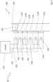
- FIGS 1 and 2 show an elevator system 100 comprising an elevator car 102 in a hoistway 104.
- the elevator system 100 may comply with the PESSRAL (Programmable Electronic Systems in Safety Related Applications for Lifts) standard.
- the elevator car 102 is configured to move up and down the hoistway 104 to transport passengers between the different landings 11a-11f in a building 10.
- a building typically includes a number of different floors and that each floor may have a landing from which the hoistway may be accessed.
- Alternate landings at which the elevator car is configured to stop may be referred to as even landings and the alternate landings located between the respective even landings may be referred to as odd landings.
- the elevator system 100 may comprise other standard components including but not limited to drive means, tension members, a counterweight, a power source and a control panel.
- the elevator system 100 comprises a plurality of landing doors 112a-f.
- Each landing door 112a in the plurality of landing doors 112a-f is located on a different respective landing 11a.
- the plurality of landing doors 112a-f provide access to the hoistway 104 when open. When a landing door 112a on a landing 11a is closed, no access to the hoistway 104 is possible from that respective landing 11a.
- the elevator car 102 is also accessible via any of the plurality of landing doors 112a-f when the elevator car 102 is located at that respective landing 11a-f and when both an elevator car door (not shown) and the landing door 112a are open.
- the plurality of landing doors 112a-f comprises one or more even landing doors located on even landings of the building 10 and one or more odd landing doors located on odd landings of the building 10.
- the even landings of the building 10 are the landings with even numbers (i.e. level 0, 2, 4, 6 etc).
- the odd landings of the building 10 are the landings with odd numbers (i.e. level 1, 3, 5, 7 etc.).
- the elevator system 100 comprises a safety system 105.
- the safety system 105 ensures the safety of service personnel while working in the hoistway 104.
- the safety system 105 comprises a controller 110.
- the elevator system 100 may comprise further controllers, each performing different functions to facilitate the operation of the elevator system 100.
- service personnel are personnel charged with carrying out service actions on an elevator system. They are distinct from non-service personnel only in that they perform actions on an elevator system beyond what would be considered "normal use".
- the actions which may be performed by service personnel include, but are not limited to, inspection and/or maintenance of the elevator system.
- the safety system 105 comprises a first safety chain 120.
- the first safety chain 120 and the controller 110 are connected such that the controller 110 can receive an even landing signal from the first safety chain 120.
- the first safety chain 120 is connected to the one or more landing doors 112a, 112c, 112e located on even landings 11a, 11c, 11e of the building 10.
- the first safety chain 120 may be connected to the one or more landing doors 112a, 112c, 112e via sensors as will be described further below.
- the first safety chain 120 is configured to transmit the even landing signal to the controller 110 when any of the one or more even landing doors 112a, 112c, 112e are open.
- the first safety chain 120 is also configured to transmit the even landing signal to the controller 110 when the elevator car 102 is located at any of the even landings 11a, 11c, 11e.
- the safety system 105 comprises a second safety chain 125.
- the second safety chain 125 and the controller 110 are connected such that the controller 110 can receive an odd landing signal from the second safety chain 125.
- the second safety chain 125 is connected to one or more landing doors 112b, 112d, 112f located on odd landings 11b, 11d, 11f of the building 10.
- the second safety chain 125 is configured to transmit the odd landing signal to the controller 110 when any of the one or more odd landing doors 112b, 112d, 112f are open.
- the second safety chain 125 is also configured to transmit the odd landing signal to the controller 110 when the elevator car 102 is located at any of the odd landings 11b, 11d, 11f.
- the first safety chain 120 comprises an even set of sensors 130.
- Each sensor in the even set of sensors 130 may be physically adjacent to a respective one of the one or more even landing doors 112a, 112c, 112e.
- the even set of sensors 130 automatically produces the even landing signal which is transmitted to the controller 110 by the first safety chain 120 either when any of the one or more even landing doors 112a, 112c, 112e is open, or when the elevator car 102 is located at any of the even landings 11a, 11c, 11e.
- the second safety chain 125 comprises an odd set of sensors 135. Each sensor in the odd set of sensors 135 may be physically adjacent to a respective one of the one or more odd landing doors 112b, 112d, 112f.
- the odd set of sensors 135 automatically produces the odd landing signal which is transmitted to the controller 110 by the second safety chain 125 either when any of the one or more odd landing doors 112b, 112d, 112f is open, or when the elevator car 102 is located at any of the odd landings 11b, 11d, 11f.
- the even set of sensors 130 comprises a plurality of even door sensors 132 and a plurality of even landing sensors 134
- the odd set of sensors 135 comprises a plurality of odd door sensors 136 and a plurality of odd landing sensors 138.
- the plurality of even door sensors 132 are configured to produce the even landing signal when any of the even landing doors 112a, 112c, 112e are open; and the plurality of odd door sensors 136 are configured to produce the odd landing signal when any of the odd landing doors 112b, 112d, 112f are open.
- the plurality of even door sensors 132 comprise a plurality of override switches (not shown).
- the plurality of override switches are configured to automatically produce the even landing signal when an even landing door 112a, 112c, 112e is opened by a manual override.
- the manual override may comprise service personnel overriding a landing door locking mechanism to open an even landing door 112a, 112c, 112e when the elevator car 102 is not located at the landing 11a, 11c, 11f associated with said even landing door 112a, 112c, 112e.
- the plurality of override switches may each comprise an electrical contact (not shown) which is opened or closed such that, when the contact is closed, current may flow through the contact, and when the contact is opened, no current may flow through the contact.
- the controller 110 may be configured to instruct the elevator system 100 to automatically enter a special operating mode when no current is received from the first safety chain 120 and no current is also received from the second safety chain 125, for example when the contact of one override switch has been opened indicating that an even landing door has been opened by a manual override and thus providing no current via the first safety chain 120, while the second safety chain 125 indicates that the elevator car 102 is located at an odd landing.
- the plurality of override switches produce the even landing signal in response to service personnel inserting a key into a lock and turning the key in the lock.
- turning the key in the lock may move the contact to the open position such that no current may flow through the contact.
- the plurality of override switches may produce the even landing signal in response to service personnel pushing a button or entering a code into a number pad.
- pressing the button or entering the code may move the contact to the open position such that no current may flow through the contact.
- turning the key, pressing the button or entering the code may move the contact into the closed position such that current may flow through the contact.
- the plurality of odd door sensors 136 comprise a plurality of override switches (not shown).
- the plurality of override switches are configured to automatically produce the odd landing signal when service personnel overrides a landing door locking mechanism to open an odd landing door when the elevator car 102 is not located at the landing associated with said odd landing door.
- the plurality of override switches produce the odd landing signal in response to service personnel inserting a key into a lock and turning the key in the lock.
- turning the key in the lock may move the contact to the open position such that no current may flow through the contact.
- the plurality of override switches may produce the odd landing signal in response to service personnel pushing a button or entering a code into a number pad.
- pressing the button or entering the code may move the contact to the open position such that no current may flow through the contact.
- turning the key, pressing the button or entering the code may move the contact into the closed position such that current may flow through the contact.
- the plurality of even landing sensors 134 comprise a plurality of proximity sensors (not shown).
- the plurality of proximity sensors are configured to produce the even landing signal in response to the elevator car 102 being located at an even landing.
- the plurality of proximity sensors may be disposed inside the hoistway 104 such that they detect when the elevator car 102 is located at an even landing.
- the plurality of proximity sensors may be connected to an elevator control system, which provides updates to the plurality of proximity sensors on the location of the elevator car 102.
- the plurality of odd landing sensors 138 comprise a plurality of proximity sensors (not shown).
- the plurality of proximity sensors are configured to produce the odd landing signal in response to the elevator car 102 being located at an odd landing.
- the plurality of proximity sensors may be disposed inside the hoistway 104 such that they detect when the elevator car 102 is located at an odd landing.
- the plurality of proximity sensors may be connected to an elevator control system, which provides updates to the plurality of proximity sensors on the location of the elevator car 102.
- the even landing signal and the odd landing signal in some examples comprises a change in the normal output from the even set of sensors 130 and the odd set of sensors 135 respectively.
- the normal output from the even set of sensors 130 and the odd set of sensors 135 may be a positive signal.
- the positive signal may be the flow of electric current.
- the positive signal may be a constant stream of data sent wirelessly.
- the even landing signal and the odd landing signal may comprise the electric current no longer flowing, or the constant stream of data sent wirelessly being interrupted.
- the normal output from the even set of sensors 130 and the odd set of sensors 135 may be a negative signal.
- the negative signal may be lack of flow of electric current, or the lack of data sent wirelessly.
- the override signal may comprise the flow of electric current or a stream of data sent wirelessly.
- both of the plurality of proximity sensors and the plurality of override sensors can produce the even landing signal or odd landing signal.
- the even landing signal and/or the odd landing signal comprise electric current no longer flowing
- the even landing signal and/or the odd landing signal may be produced by a break in the electrical circuit at the plurality of proximity sensors and/or the plurality of override sensors.
- the controller 110 monitors the first safety chain 120.
- the controller 110 may monitor the electrical current flowing through the first safety chain 120 so that it can detect when the even landing signal is produced.
- the controller 110 monitors the second safety chain 125.
- the controller 110 monitors the electrical current flowing through the second safety chain 125 so that it can detect when the odd landing signal is produced.
- electrical current will be running through at least one of the first safety chain 120 and the second safety chain 125 at any time.
- the landing doors will only open at the landings at which the elevator has stopped such that the controller 110 will receive only one of the even landing signal and the odd landing signal at any one time.
- the controller 110 if the controller 110 receives the even landing signal and the odd landing signal at the same time (for example when electrical current is not running through either of the first safety chain 120 and the second safety chain 125) the controller 110 automatically causes the elevator system 100 to enter a special operation mode.
- the controller 110 is configured to automatically instruct the elevator system 100 to enter the special operating mode in response to both of the even landing signal and the odd landing signal being present.
- the special operation mode is a service mode.
- the service mode is a maintenance mode and/or an inspection mode, which is associated with a PESSRAL safety system.
- the elevator system 100 when in the special operation mode, is configured to prevent the elevator car 102 from moving.
- the elevator system 100 may deploy a safety brake and/or a safety barrier such as an upper balustrade that is disposed on the roof of the elevator car 102.
- the upper balustrade may prevent service personnel working atop the elevator car 102 from falling into the hoistway 104.
- the safety brake may prevent the elevator car 102 from moving and may not be overridden until the elevator system 100 re-enters the normal mode.
- elevator call buttons on landings in the building are disabled when the elevator system 100 is in the special operating mode.
- a safe distance limit between the top of the elevator car 102 and the top of the hoistway 104 is set, and the elevator car 102 is prevented from moving past this limit towards the top of the hoistway 104.
- the elevator system 100 may deploy additional lighting and sound systems to any of the hoistway 104, the elevator car 102 and the plurality of landing doors 112a-f.
- the lighting and sound systems may alert nearby people that servicing is being carried out, and may assist the service personnel in performing their duties.
- the elevator system 100 When in the special operation mode, the elevator system 100 is in a safe state for the hoistway 104 to be accessed and for service procedures such as maintenance or inspection to be carried out.
- the controller 110 may instruct the elevator system 100 to return to the normal mode. In such examples, the controller 110 may instruct the elevator system 100 to re-enter the normal operation mode when either of the even landing signal and the odd landing signal is no longer received by the controller 110. In other examples, the controller 110 may instruct the elevator system 100 to re-enter the normal operation mode when the normal output is received from either of the even set of sensors 130 and the odd set of sensors 135.
- the plurality of override switches may produce the normal output in response to the key being removed from the lock.
- the elevator system 100 may return to the normal mode following further instruction from service personnel.
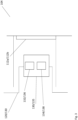
- Figure 4 depicts a method 300 of operating the safety system 105 of the elevator system 100 described above is also disclosed.
- the method 300 comprises the first safety chain 120 producing the even landing signal (step 302) in response to the even landing door being opened, or in response to the elevator car 102 arriving at the even landing.
- the even set of sensors 130 may produce the even landing signal.
- the method 300 further comprises the second safety chain 125 producing the odd landing signal (step 304) in response to the odd landing door being opened, or in response to the elevator car 102 arriving at the odd landing.
- the odd set of sensors 135 may produce the odd landing signal.
- the method 300 further comprises the controller 110 automatically instructing the elevator system 100 to enter the special operating mode in response to the controller 110 receiving both of the even landing signal and the odd landing signal (step 306).
- the controller 110 automatically instructs the elevator system 100 to enter the special operating mode in response to the controller 110 simultaneously receiving both of the even landing signal and the odd landing signal.
- "automatically instructing" is taken to mean “immediately instructing”.
- the controller 110 automatically instructs the elevator system 100 to enter the special operating mode in response to both of the even landing signal and the odd landing signal being present.
- the method 300 further comprises the elevator system 100 deploying additional safety measures in response to entering the special operating mode (step 308).
- the additional safety measures comprise deploying a safety brake on the elevator car 102, activating lighting and sound systems in the hoistway 104, on the elevator car 102 or at the plurality of landing doors 112a-f, and deploying a guard rail, which may be an upper balustrade, on the elevator car 102.
- the method 300 further comprises the controller 110 instructing the elevator system 100 to re-enter the normal operating mode in response to the first safety chain 120 and/or the second safety chain 125 no longer producing the even landing signal or the odd landing signal respectively (step 310). In some examples, the method 300 further comprises the controller 110 instructing the elevator system 100 to re-enter the normal operating mode in response to the first safety chain 120 and/or the second safety chain 125 producing the normal output.
- the elevator car may be used in a roped or ropeless elevator system, or another type of conveyance system.
Landscapes
- Engineering & Computer Science (AREA)
- Automation & Control Theory (AREA)
- Computer Networks & Wireless Communication (AREA)
- Elevator Door Apparatuses (AREA)
- Elevator Control (AREA)
Priority Applications (3)
| Application Number | Priority Date | Filing Date | Title |
|---|---|---|---|
| EP23306897.2A EP4549362B1 (de) | 2023-11-02 | 2023-11-02 | Sicherheitssystem für aufzug, verfahren zum betreiben eines sicherheitssystems und ein computerprogrammprodukt zur steuerung eines sicherheitsystems |
| CN202411526634.0A CN119929613A (zh) | 2023-11-02 | 2024-10-30 | 电梯安全系统 |
| US18/933,143 US20250145411A1 (en) | 2023-11-02 | 2024-10-31 | Elevator safety system |
Applications Claiming Priority (1)
| Application Number | Priority Date | Filing Date | Title |
|---|---|---|---|
| EP23306897.2A EP4549362B1 (de) | 2023-11-02 | 2023-11-02 | Sicherheitssystem für aufzug, verfahren zum betreiben eines sicherheitssystems und ein computerprogrammprodukt zur steuerung eines sicherheitsystems |
Publications (2)
| Publication Number | Publication Date |
|---|---|
| EP4549362A1 true EP4549362A1 (de) | 2025-05-07 |
| EP4549362B1 EP4549362B1 (de) | 2026-04-01 |
Family
ID=88839720
Family Applications (1)
| Application Number | Title | Priority Date | Filing Date |
|---|---|---|---|
| EP23306897.2A Active EP4549362B1 (de) | 2023-11-02 | 2023-11-02 | Sicherheitssystem für aufzug, verfahren zum betreiben eines sicherheitssystems und ein computerprogrammprodukt zur steuerung eines sicherheitsystems |
Country Status (3)
| Country | Link |
|---|---|
| US (1) | US20250145411A1 (de) |
| EP (1) | EP4549362B1 (de) |
| CN (1) | CN119929613A (de) |
Citations (3)
| Publication number | Priority date | Publication date | Assignee | Title |
|---|---|---|---|---|
| WO2003043928A1 (en) * | 2001-11-16 | 2003-05-30 | Otis Elevator Company | Hoistway access detection system |
| WO2005118453A1 (en) * | 2004-06-03 | 2005-12-15 | Otis Elevator Company | Elevator hoistway access detection |
| EP2671836A1 (de) * | 2011-02-02 | 2013-12-11 | Mitsubishi Electric Corporation | Sicherheitssteuervorrichtung für aufzüge |
-
2023
- 2023-11-02 EP EP23306897.2A patent/EP4549362B1/de active Active
-
2024
- 2024-10-30 CN CN202411526634.0A patent/CN119929613A/zh active Pending
- 2024-10-31 US US18/933,143 patent/US20250145411A1/en active Pending
Patent Citations (3)
| Publication number | Priority date | Publication date | Assignee | Title |
|---|---|---|---|---|
| WO2003043928A1 (en) * | 2001-11-16 | 2003-05-30 | Otis Elevator Company | Hoistway access detection system |
| WO2005118453A1 (en) * | 2004-06-03 | 2005-12-15 | Otis Elevator Company | Elevator hoistway access detection |
| EP2671836A1 (de) * | 2011-02-02 | 2013-12-11 | Mitsubishi Electric Corporation | Sicherheitssteuervorrichtung für aufzüge |
Also Published As
| Publication number | Publication date |
|---|---|
| US20250145411A1 (en) | 2025-05-08 |
| CN119929613A (zh) | 2025-05-06 |
| EP4549362B1 (de) | 2026-04-01 |
Similar Documents
| Publication | Publication Date | Title |
|---|---|---|
| KR101481568B1 (ko) | 엘리베이터 안전 시스템 및 방법 | |
| CN103917471B (zh) | 电梯安全控制装置 | |
| EP2671836B1 (de) | Sicherheitssteuervorrichtung für aufzüge | |
| CN112135787B (zh) | 安全切换系统以及用于在正常运行模式与检查运行模式之间切换电梯设备的方法 | |
| EP2765108A1 (de) | Verfahren zur Bereitstellung von Schachtzugang in einem Aufzug | |
| CN107848743A (zh) | 电梯控制系统 | |
| EP2096072B1 (de) | Brandevakuierungsunterstützungssystem und brandtürsteuervorrichtung | |
| US20090255761A1 (en) | Elevator Control System | |
| CN112456267B (zh) | 一种用于电梯检修运行的电气安全检测控制电路 | |
| EP1867594B1 (de) | Aufzugssystem und betriebssteuerungsverfahren dafür | |
| EP4549362A1 (de) | Sicherheitssystem für aufzug | |
| KR100975758B1 (ko) | 엘리베이터 구조운전 회로 | |
| JP3412401B2 (ja) | エレベーターの非常時運転装置 | |
| EP4549356A1 (de) | Sicherheitssystem für aufzug | |
| JP4737941B2 (ja) | エレベータ制御装置 | |
| JP2004359405A (ja) | エレベータの地震時遠隔救出方法 | |
| JP6537539B2 (ja) | エレベーターの制御装置および制御方法 | |
| JP6471202B1 (ja) | エレベータの制御システム | |
| JP6715214B2 (ja) | エレベーター及びエレベーターの制御方法、並びにエレベーターの管制制御システム | |
| JP2021195224A (ja) | エレベーターの制御装置と制御方法 | |
| JP2021054582A (ja) | エレベーターのピットアウト連絡支援方法、及びエレベーターのピットアウト連絡支援システム | |
| JP2011063420A (ja) | エレベータ制御装置 | |
| US20230348231A1 (en) | Access control arrangement, mobile device, conveyor system, and method for controlling access in conveyor system | |
| CN109132754B (zh) | 电梯装置 | |
| JP2003312957A (ja) | エレベータ制御装置 |
Legal Events
| Date | Code | Title | Description |
|---|---|---|---|
| PUAI | Public reference made under article 153(3) epc to a published international application that has entered the european phase |
Free format text: ORIGINAL CODE: 0009012 |
|
| STAA | Information on the status of an ep patent application or granted ep patent |
Free format text: STATUS: REQUEST FOR EXAMINATION WAS MADE |
|
| 17P | Request for examination filed |
Effective date: 20240627 |
|
| AK | Designated contracting states |
Kind code of ref document: A1 Designated state(s): AL AT BE BG CH CY CZ DE DK EE ES FI FR GB GR HR HU IE IS IT LI LT LU LV MC ME MK MT NL NO PL PT RO RS SE SI SK SM TR |
|
| GRAP | Despatch of communication of intention to grant a patent |
Free format text: ORIGINAL CODE: EPIDOSNIGR1 |
|
| STAA | Information on the status of an ep patent application or granted ep patent |
Free format text: STATUS: GRANT OF PATENT IS INTENDED |
|
| INTG | Intention to grant announced |
Effective date: 20250708 |
|
| GRAJ | Information related to disapproval of communication of intention to grant by the applicant or resumption of examination proceedings by the epo deleted |
Free format text: ORIGINAL CODE: EPIDOSDIGR1 |
|
| STAA | Information on the status of an ep patent application or granted ep patent |
Free format text: STATUS: REQUEST FOR EXAMINATION WAS MADE |
|
| GRAP | Despatch of communication of intention to grant a patent |
Free format text: ORIGINAL CODE: EPIDOSNIGR1 |
|
| INTC | Intention to grant announced (deleted) | ||
| STAA | Information on the status of an ep patent application or granted ep patent |
Free format text: STATUS: GRANT OF PATENT IS INTENDED |
|
| INTG | Intention to grant announced |
Effective date: 20251217 |
|
| GRAS | Grant fee paid |
Free format text: ORIGINAL CODE: EPIDOSNIGR3 |
|
| GRAA | (expected) grant |
Free format text: ORIGINAL CODE: 0009210 |
|
| STAA | Information on the status of an ep patent application or granted ep patent |
Free format text: STATUS: THE PATENT HAS BEEN GRANTED |