EP4546641A1 - Systeme und verfahren zur strommessung in motorsteuerungsanwendungen - Google Patents
Systeme und verfahren zur strommessung in motorsteuerungsanwendungen Download PDFInfo
- Publication number
- EP4546641A1 EP4546641A1 EP24205368.4A EP24205368A EP4546641A1 EP 4546641 A1 EP4546641 A1 EP 4546641A1 EP 24205368 A EP24205368 A EP 24205368A EP 4546641 A1 EP4546641 A1 EP 4546641A1
- Authority
- EP
- European Patent Office
- Prior art keywords
- coupled
- phase
- shunt resistor
- motor
- resistor network
- Prior art date
- Legal status (The legal status is an assumption and is not a legal conclusion. Google has not performed a legal analysis and makes no representation as to the accuracy of the status listed.)
- Pending
Links
Images

Classifications
-
- H—ELECTRICITY
- H02—GENERATION; CONVERSION OR DISTRIBUTION OF ELECTRIC POWER
- H02P—CONTROL OR REGULATION OF ELECTRIC MOTORS, ELECTRIC GENERATORS OR DYNAMO-ELECTRIC CONVERTERS; CONTROLLING TRANSFORMERS, REACTORS OR CHOKE COILS
- H02P27/00—Arrangements or methods for the control of AC motors characterised by the kind of supply voltage
- H02P27/04—Arrangements or methods for the control of AC motors characterised by the kind of supply voltage using variable-frequency supply voltage, e.g. inverter or converter supply voltage
- H02P27/06—Arrangements or methods for the control of AC motors characterised by the kind of supply voltage using variable-frequency supply voltage, e.g. inverter or converter supply voltage using DC to AC converters or inverters
- H02P27/08—Arrangements or methods for the control of AC motors characterised by the kind of supply voltage using variable-frequency supply voltage, e.g. inverter or converter supply voltage using DC to AC converters or inverters with pulse width modulation
-
- H—ELECTRICITY
- H02—GENERATION; CONVERSION OR DISTRIBUTION OF ELECTRIC POWER
- H02P—CONTROL OR REGULATION OF ELECTRIC MOTORS, ELECTRIC GENERATORS OR DYNAMO-ELECTRIC CONVERTERS; CONTROLLING TRANSFORMERS, REACTORS OR CHOKE COILS
- H02P21/00—Arrangements or methods for the control of electric machines by vector control, e.g. by control of field orientation
- H02P21/22—Current control, e.g. using a current control loop
-
- H—ELECTRICITY
- H02—GENERATION; CONVERSION OR DISTRIBUTION OF ELECTRIC POWER
- H02M—APPARATUS FOR CONVERSION BETWEEN AC AND AC, BETWEEN AC AND DC, OR BETWEEN DC AND DC, AND FOR USE WITH MAINS OR SIMILAR POWER SUPPLY SYSTEMS; CONVERSION OF DC OR AC INPUT POWER INTO SURGE OUTPUT POWER; CONTROL OR REGULATION THEREOF
- H02M1/00—Details of apparatus for conversion
- H02M1/0003—Details of control, feedback or regulation circuits
- H02M1/0009—Devices or circuits for detecting current in a converter
-
- H—ELECTRICITY
- H02—GENERATION; CONVERSION OR DISTRIBUTION OF ELECTRIC POWER
- H02P—CONTROL OR REGULATION OF ELECTRIC MOTORS, ELECTRIC GENERATORS OR DYNAMO-ELECTRIC CONVERTERS; CONTROLLING TRANSFORMERS, REACTORS OR CHOKE COILS
- H02P21/00—Arrangements or methods for the control of electric machines by vector control, e.g. by control of field orientation
- H02P21/14—Estimation or adaptation of machine parameters, e.g. flux, current or voltage
- H02P21/18—Estimation of position or speed
-
- H—ELECTRICITY
- H02—GENERATION; CONVERSION OR DISTRIBUTION OF ELECTRIC POWER
- H02P—CONTROL OR REGULATION OF ELECTRIC MOTORS, ELECTRIC GENERATORS OR DYNAMO-ELECTRIC CONVERTERS; CONTROLLING TRANSFORMERS, REACTORS OR CHOKE COILS
- H02P21/00—Arrangements or methods for the control of electric machines by vector control, e.g. by control of field orientation
- H02P21/14—Estimation or adaptation of machine parameters, e.g. flux, current or voltage
- H02P21/20—Estimation of torque
-
- H—ELECTRICITY
- H02—GENERATION; CONVERSION OR DISTRIBUTION OF ELECTRIC POWER
- H02P—CONTROL OR REGULATION OF ELECTRIC MOTORS, ELECTRIC GENERATORS OR DYNAMO-ELECTRIC CONVERTERS; CONTROLLING TRANSFORMERS, REACTORS OR CHOKE COILS
- H02P27/00—Arrangements or methods for the control of AC motors characterised by the kind of supply voltage
- H02P27/04—Arrangements or methods for the control of AC motors characterised by the kind of supply voltage using variable-frequency supply voltage, e.g. inverter or converter supply voltage
- H02P27/06—Arrangements or methods for the control of AC motors characterised by the kind of supply voltage using variable-frequency supply voltage, e.g. inverter or converter supply voltage using DC to AC converters or inverters
- H02P27/08—Arrangements or methods for the control of AC motors characterised by the kind of supply voltage using variable-frequency supply voltage, e.g. inverter or converter supply voltage using DC to AC converters or inverters with pulse width modulation
- H02P27/12—Arrangements or methods for the control of AC motors characterised by the kind of supply voltage using variable-frequency supply voltage, e.g. inverter or converter supply voltage using DC to AC converters or inverters with pulse width modulation pulsing by guiding the flux vector, current vector or voltage vector on a circle or a closed curve, e.g. for direct torque control
Definitions
- This disclosure relates generally to electronic circuits, and more specifically, to systems and methods for current sensing in motor control applications.
- IC Integrated Circuit
- SoC System-on-Chip
- an SoC may be used to operate another device, such as an electrical motor.
- a 3-phase motor uses large amounts of power.
- the SoC may implement Space Vector Modulation (SVM) techniques for producing Pulse-Width Modulated (PWM) signals to drive 3-phase motors at varying speeds.
- SVM Space Vector Modulation
- these systems and methods may provide a triple-shunt resistor topology-e.g., in the phase legs of a 3-phase H-bridge voltage inverter with power transistors-that enables 3-phase current sensing using a single Operational Amplifier (Op Amp).
- Op Amp Operational Amplifier
- these systems and methods enable the reconstruction of all 3-phase currents based on a voltage signal provided by the Op Amp and measured across the entire triple-shunt resistor network.
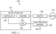
- FIG. 1 is a block diagram of an example of system 100 for current sensing in motor control applications.
- system 100 includes motor controller 101 coupled to inverter 104 and to shunt resistor network 105, and inverter 104 is coupled to 3-phase motor 107.
- motor 107 may include any type of 3-phase motor, such as a 3-phase induction motor, a 3-phase synchronous motor, etc. More generally, however, motor 107 may have any number of phases (e.g., four, five, six, etc.).
- Motor controller 101 includes controller 102, Space Vector Modulator (SVM) and Pulse Width Modulator (PWM) or "SVM+PWM” block or module 103, and Analog-to-Digital Converter (ADC) 106.
- SVM provides a modulation technique for calculating a proper voltage vector, which is applied to motor 107 using PWM.
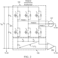
- SVM+PWM block 103 is configured to control certain aspects of the operation of power transistors (T 1 -T 6 ) in inverter 104 ( FIG. 2 ).
- ADC 106 samples a voltage signal across shunt resistor network 105 (via the output of Op Amp 202).
- DC bus voltage V DC is applied across a voltage divider including resistors R A and R B .
- Terminal 201 is sampled by ADC 301 ( FIG. 3 ).
- Inverter 104 includes a 3-phase H-bridge with power transistors T 1 -T 6 . Each phase leg of the H-bridge has a pair of complementary power transistors.
- Transistors T 1 -T 6 are controlled by PWM signals.
- motor controller 101 provides PWM signals to T 1 -T 6 over consecutive PWM periods so as to drive motor 107 using a control algorithm executed by SVM+PWM block 103.
- SVM+PWM block 103 is configured to generate PWM signals to control T 1 -T 6 , which produce the required modulated voltage to drive motor 107 at the desired speed or torque.
- inverter 104 is illustrated as having a particular topology, it should be noted that, in other implementations, inverter 104 may have any other suitable topology.
- the three inverter phase legs may be mutually swapped with respect to their position within shunt resistor network 105 (provided the derived equations reflect changes in the topology).
- SVM+PWM block 103 may be configured to use a voltage vector diagram in the shape of a hexagon having 6 sectors (I-VI). Each adjacent vector pair forms one of the 6 sectors. Moreover, each vector (V0-V7) may correspond to a respective one of sectors I-VI, such that the boundaries of each sector I-VI are usable to control the on/off ("1" or "0") states of transistors T 1 -T 6 , as shown in Table 1: Table I - SVM Voltage Vectors and Corresponding Transistor States Vector (xyz) T 1 T 2 T 3 T 4 T 5 T 6 V0 (000) 0 1 0 1 0 1 V1 (100) 1 0 0 1 0 1 V2 (110) 1 0 1 0 0 1 V3 (010) 0 1 1 0 0 1 V4 (011) 0 1 1 0 1 0 V5 (001) 0 1 0 1 1 0 V6 (101) 1 0 0 1 1 0 V7 (111) 1
- voltage vectors may be generated by SVM+PWM block 103 based upon commands (e.g., indicating a sector, required PWM, etc.) issued by controller 102, and those voltage vectors may be applied to T 1 -T 6 to control motor 107.
- inverter 104 is coupled to shunt resistor network 105, and shunt resistor network 105 is coupled to motor controller 101 via Op Amp 202.
- the topology of shunt resistor network 105 includes: first resistor R 1 coupled to an inverting input of Op Amp 202 and to a first phase leg (T 1 , T 2 ) of inverter 104 (e.g., at the source terminal of T 2 ), second resistor R 2 coupled to the first and second phase leg (Ts, T 4 ) of inverter 104 (e.g., at the source terminal of T 4 ), and third resistor R 3 coupled to the second and third phase leg (T 5 , T 6 ) of inverter 104 (e.g., at the source terminal of T 6 ), as shown.
- first resistor R 1 coupled to an inverting input of Op Amp 202 and to a first phase leg (T 1 , T 2 ) of inverter 104 (e.g., at the source terminal of T 2 )
- second resistor R 2 coupled to the first and second phase leg (Ts, T 4 ) of inverter 104 (e.g., at the source terminal
- each of R 1 -R 3 may have the same resistance value, or a different value.
- the third phase leg of inverter 104 is coupled to a non-inverting input of Op Amp 202.
- this particular topology may enable systems and methods described herein to reconstruct of all 3-phase currents based upon a single voltage signal provided by Op Amp 202 and measured across entire triple-shunt resistor network 105 ( i.e. , as a voltage drop between R 1 and R 3 ).
- each additional phase (e.g. , phase " N ”) may be provided by an additional phase leg in inverter 104, coupled to a preceding phase leg by an additional resistor (e.g. , R N ), such that Op Amp 202 is coupled to R1 and to the last resistor in shunt resistor network 105.
- additional resistor e.g. , R N
- the output of motor 107 may be provided to position/speed/torque processing module 303, shown in FIG. 3 .
- the output of motor 107 may be used by processing module 303 to estimate or calculate a position, speed, or torque of motor 107 during its operation using one or more sensors coupled thereto.
- FIG. 3 is a block diagram of examples of motor controller 101.
- motor controller may comprise a processor, microcontroller, Systems-On-Chip (SoC), or the like (collectively referred to as "processor").
- SoC Systems-On-Chip
- motor controller 101 includes motor control block or portion 102A and current reconstruction module 102B (combined as “controller 102" in FIG. 1 ).
- Motor control block 102A sends commands to SVM+PWM block 103 to produce 6 control signals that are provided to Gate Driver Unit (GDU) 302, which may be external or internal with respect to controller 102.
- GDU 302 in turn applies each of corresponding outputs to the gates of T 1 -T 6
- motor control block 102A receives the output of ADC 301, which includes an indication of the voltage at terminal 201, and which along with a priori knowledge of R A and R B , allow the value of DC bus voltage V DC to be determined. Additionally, or alternatively, to control the operation of motor 107, motor control block 102A receives the output of position/speed/torque processing module 303 based on inputs received from motor 107 or from sensors coupled thereto.
- motor control block 102A receives, from current reconstruction module 102B: a first reconstructed current (i a ) for phase A, a second reconstructed current (i b ) for phase B, and a third reconstructed current (i c ) for phase C.
- zero vector refers to a voltage vector of zero magnitude translating into transistors T1-T6 on/off state as all high-side or all low-side transistors in all phase legs switched on.
- active vector refers to a voltage vector of non-zero magnitude translating into inverter transistors T1-T6 on/off state as any switching state other than zero vector (at the same time the on/off states where both of the transistors in the same phase leg are in the same state are not considered an active vector).
- active vectors there are six active vectors (V1-V6) and two zero vectors (V0,V7)).
- vector period (of active or zero vector) refers to a portion of a PWM period during which the particular active or zero vector is generated by the inverter.
- dominant vector (of a particular sector) refers to an active vector of a particular sector with the highest magnitude of all the active vectors generated during a particular PWM period.
- current reconstruction block 102B receives a signal indicative of a voltage drop across R 1 -R 3 of shunt resistor network 105, as detected by Op Amp 202 and provided to ADC 106. Measurements may be performed during the active voltage vector period as well as during the zero vector period (which leads to voltage drop u 2 ), with all bottom transistors T 2 , T 4 , and T 6 turned on ( i.e. , using vector V0).
- Measurements performed during the active voltage vector period may be used to determine voltage drop u 1 , as described below. Conversely, measurements performed during a zero vector period may be used to determine voltage drop u 2 .
- the zero-voltage vector V7 with high-side transistors T 1 , T 3 , and T 5 turned on (111) may not be used for current estimation purposes (the "111" vector may still be used when operating motor 107, in which case the current estimation process is placed on hold).
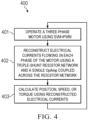
- FIG. 4 is a flowchart of an example of method 400 for current sensing in motor control applications.
- method 400 may be performed, at least in part, by motor controller 101.
- motor controller 101 operates 3-phase motor 107 using SVM+PWM block 103.
- motor controller 101 reconstructs electrical currents i a -i c flowing in each phase of motor 107 using triple-shunt resistor network 105 and single Op Amp 202 coupled across the entire network 105.
- motor controller 101 may determine voltage drop u 2 across shunt resistor network 105 at each zero vector. Motor controller 101 may also determine voltage drop u 1 across shunt resistor network 105 during each of a plurality of active vector periods.
- u 2 may be modeled by a different equation in each of the plurality of active vector periods.
- Each of the plurality of active vector periods may include the concurrent application of two voltage vectors to the electric motor, and there may be six active vector periods at each rotation of motor 107.
- motor controller 101 may be configured to solve a different system of equations for each of the plurality of active vector periods, as described in more detail below.
- motor controller 101 may calculate a position, speed, and torque of motor 107, at least in part, based upon the reconstructed electrical currents i a -i c using any suitable technique before control returns to 401.
- current reconstruction module 102B may be configured to detect a dominant vector based at least in part upon the duty cycles/switching states generated by SPM+PWM module 103, and, in response thereto, perform a number of operations.
- current reconstruction module 102B may be configured to determine voltage drop u 1 across shunt resistor network 105, where u 1 represents a unique analog value for each voltage vector applied to motor 107. There are 6 active vectors in inverter 104, and each of these vectors leads to a unique voltage drop u 1 .
- Current reconstruction equations for respective SVM sectors are determined based on u 1 and u 2 .
- the voltage is composed of zero vectors and two active vectors.
- Currents i a , i b , and i c are reconstructed from: (i) u 1 measured during the dominant active vector period, and (ii) u 2 measured during zero voltage period- i.e ., when T2, T4, and T6 are on.
- systems and methods described herein provide topologies for a shunt resistor network coupled to a single Op Amp to measure each 3-phase inverter/motor current i a , i b , and i c .
- these systems and methods may be used in motor control applications where a single shunt resistor configuration (e.g., in the DC link) is not desirable or possible (e.g., due to customer preference, application preference, etc.), therefore three shunt resistors must be used yet the deployment of three external Op Amps would be design or cost prohibitive.
- a circuit may include a shunt resistor network coupled to an inverter having a plurality of phase legs, where each of the plurality of phase legs is configured to drive a respective phase of an electrical motor, and an Operational Amplifier (Op Amp) coupled across the shunt resistor network, where the Op Amp enables a processor to reconstruct electrical currents in each of the plurality of phase legs.
- Op Amp Operational Amplifier
- a circuit may include a shunt resistor network coupled to an inverter having a plurality of phase legs, where each of the plurality of phase legs is configured to drive a respective phase of an electrical motor, and an Op Amp coupled across the shunt resistor network, where the Op Amp enables a processor to reconstruct electrical currents in each of the plurality of phase legs.
- the electrical motor may include a 3-phase electrical motor, where the plurality of phase legs includes three phase legs, and where the shunt resistor network includes three shunt resistors.
- a first shunt resistor may be coupled between a terminal and a first phase leg of the plurality of legs, a second shunt may be is coupled between the first phase leg and a second phase leg of the plurality of legs, and a third shunt resistor may be coupled between the second phase leg and a third phase leg of the plurality of legs.
- a non-inverting input of the Op Amp may be coupled to the third phase leg, an inverting input of the Op Amp is coupled to the terminal, and an output of the Op Amp is coupled to an input of an Analog-to-Digital Converter (ADC).
- ADC Analog-to-Digital Converter
- the processor may be configured to determine a voltage drop across the shunt resistor network at a zero vector. Additionally, or alternatively, to reconstruct the electrical currents, the processor is configured to determine a voltage drop across the shunt resistor network during each of a plurality of active vector periods.
- the second voltage drop may be modeled by a different equation in each of the plurality of active vector periods.
- Each of the plurality of active vector periods may include the concurrent application of two voltage vectors to the electric motor, and there may be six active vector periods at each rotation of the electric motor.
- the processor may be configured to solve a different system of equations for each of the plurality of active vector periods.
- the processor may also be configured to determine a position, a speed, or a torque of the electrical motor based, at least in part, upon the reconstructed electrical currents.
- an electronic device may include a processor and a memory coupled to the processor, the memory having program instructions stored thereon that, upon execution, cause the device to: control a 3-phase motor; and determine electrical currents in each of the three phases using: (i) a shunt resistor network comprising a resistor for each phase, and (ii) an Op Amp coupled across the shunt resistor network, where a first resistor is coupled between a terminal and a first phase leg of an inverter, a second resistor is coupled between the first phase leg and a second phase leg of the inverter, and a third resistor is coupled between the second phase leg and a third phase leg of the inverter.
- the Op Amp may be coupled between the terminal and the third phase leg.
- the program instructions upon execution, may cause the device to control the 3-phase motor using SVM. Additionally, or alternatively, the program instructions, upon execution, may cause the device to control the 3-phase motor using PWM.
- the processor may be configured to determine a voltage drop across the shunt resistor network at a zero vector. Additionally, or alternatively, to determine the electrical currents, the processor is configured to determine a voltage drop across the shunt resistor network during each of a plurality of active vector periods.
- a method may include operating a 3-phase motor using an SVM+PWM module and reconstructing an electrical current flowing in each of the three phases of the motor using a triple-shunt resistor network and a single Op Amp coupled across the triple-shunt resistor network.
- the single Op Amp may be coupled to an ADC, and the ADC may be coupled to a processor configured to reconstruct the electrical currents.
- reconstructing the electrical currents may include determining a first voltage drop across the triple-shunt resistor network at a zero vector, and a second voltage drop across the triple-shunt resistor network during each of a plurality of active vector periods.
- the method may also include determining a position, a speed, or a torque of the 3-phase motor, at least in part, based upon the reconstructed electrical currents.
- systems and methods described herein may be incorporated into a wide range of electronic devices including, for example, computer systems or Information Technology (IT) products; consumer devices or appliances; scientific instrumentation; industrial robotics; medical or laboratory electronics; transportation vehicles such as automobiles, buses, trucks, trains, watercraft, aircraft, etc.; military equipment, etc. More generally, these systems and methods may be incorporated into any device, product, or system having one or more electric motors subject to motor control.
- IT Information Technology
Landscapes
- Engineering & Computer Science (AREA)
- Power Engineering (AREA)
- Inverter Devices (AREA)
- Control Of Ac Motors In General (AREA)
Applications Claiming Priority (1)
| Application Number | Priority Date | Filing Date | Title |
|---|---|---|---|
| US18/491,896 US12506430B2 (en) | 2023-10-23 | 2023-10-23 | Systems and methods for current sensing in motor control applications |
Publications (1)
| Publication Number | Publication Date |
|---|---|
| EP4546641A1 true EP4546641A1 (de) | 2025-04-30 |
Family
ID=93037275
Family Applications (1)
| Application Number | Title | Priority Date | Filing Date |
|---|---|---|---|
| EP24205368.4A Pending EP4546641A1 (de) | 2023-10-23 | 2024-10-08 | Systeme und verfahren zur strommessung in motorsteuerungsanwendungen |
Country Status (2)
| Country | Link |
|---|---|
| US (1) | US12506430B2 (de) |
| EP (1) | EP4546641A1 (de) |
Citations (3)
| Publication number | Priority date | Publication date | Assignee | Title |
|---|---|---|---|---|
| JP6065998B2 (ja) * | 2016-02-19 | 2017-01-25 | 日本精工株式会社 | 電動パワーステアリング装置 |
| US9966889B2 (en) * | 2013-05-12 | 2018-05-08 | Infineon Technologies Ag | Optimized control for synchronous motors |
| US20220200440A1 (en) * | 2019-04-11 | 2022-06-23 | Ls Electric Co., Ltd. | Overcurrent protection inverter |
Family Cites Families (2)
| Publication number | Priority date | Publication date | Assignee | Title |
|---|---|---|---|---|
| WO2011003220A1 (en) | 2009-07-09 | 2011-01-13 | Texas Instruments Incorporated | Inverter current measurement using shunt resistor |
| US8907611B2 (en) | 2011-07-14 | 2014-12-09 | Texas Instruments Incorporated | Method and apparatus for space vector pulse width modulation of a three-phase current construction with single DC-link shunt |
-
2023
- 2023-10-23 US US18/491,896 patent/US12506430B2/en active Active
-
2024
- 2024-10-08 EP EP24205368.4A patent/EP4546641A1/de active Pending
Patent Citations (3)
| Publication number | Priority date | Publication date | Assignee | Title |
|---|---|---|---|---|
| US9966889B2 (en) * | 2013-05-12 | 2018-05-08 | Infineon Technologies Ag | Optimized control for synchronous motors |
| JP6065998B2 (ja) * | 2016-02-19 | 2017-01-25 | 日本精工株式会社 | 電動パワーステアリング装置 |
| US20220200440A1 (en) * | 2019-04-11 | 2022-06-23 | Ls Electric Co., Ltd. | Overcurrent protection inverter |
Non-Patent Citations (1)
| Title |
|---|
| ALESSIO CORSARO ET AL: "EMC design guides for motor control applications", 1 June 2015 (2015-06-01), XP055599122, Retrieved from the Internet <URL:https://www.st.com/content/ccc/resource/technical/document/application_note/f7/f4/51/8d/a1/c5/47/8e/DM00182773.pdf/files/DM00182773.pdf/jcr:content/translations/en.DM00182773.pdf> [retrieved on 20190625] * |
Also Published As
| Publication number | Publication date |
|---|---|
| US20250132709A1 (en) | 2025-04-24 |
| US12506430B2 (en) | 2025-12-23 |
Similar Documents
| Publication | Publication Date | Title |
|---|---|---|
| US8582335B2 (en) | Inverter apparatus | |
| JP3674578B2 (ja) | 三相インバータの電流検出装置 | |
| US11271503B2 (en) | Controller, motor control system having the controller, and electric power steering system having the motor control system | |
| US9557351B2 (en) | Sensorless current sensing methods for power electronic converters | |
| CN101983322A (zh) | 温度检测电路 | |
| EP3779386B1 (de) | System und verfahren zur modellierung von thermischen kreisläufen | |
| EP3537590B1 (de) | Halbbrückentreiberschaltung, zugehörige integrierte schaltung und system | |
| Schubert et al. | Semiconductor temperature and condition monitoring using gate-driver-integrated inverter output voltage measurement | |
| JP2017123704A (ja) | 電力変換装置 | |
| CN111656669B (zh) | 控制装置 | |
| US20210006189A1 (en) | Controller, motor control system having the controller, and electric power steering system having the motor control system | |
| EP4546641A1 (de) | Systeme und verfahren zur strommessung in motorsteuerungsanwendungen | |
| JP7704958B2 (ja) | 電流検出装置及びこれを備えるモータ駆動装置 | |
| US11374521B2 (en) | Motor resistance and inductance values from initial position detection timing parameters | |
| CN111034005B (zh) | 逆变器的控制方法、马达驱动单元、马达模块以及电动助力转向装置 | |
| JP6890700B2 (ja) | 電力変換装置 | |
| WO2020080170A1 (ja) | 故障診断方法、電力変換装置、モータモジュールおよび電動パワーステアリング装置 | |
| JPWO2019220780A1 (ja) | 故障診断方法、電力変換装置、モータモジュールおよび電動パワーステアリング装置 | |
| US11770085B2 (en) | Method for operating an electric machine | |
| KR102122576B1 (ko) | 모터 구동 제어 장치 및 방법 | |
| US12166440B2 (en) | Current monitoring and circuit temperature measurements | |
| JPH1028382A (ja) | インバータの出力段における電流検出法 | |
| US20260121565A1 (en) | Motor control device and motor unit | |
| Jeong et al. | Expansion of reconstruction areas for current measurement using three shunt resistors in three leg two-phase inverters | |
| US20240175960A1 (en) | Hybrid current sense system |
Legal Events
| Date | Code | Title | Description |
|---|---|---|---|
| PUAI | Public reference made under article 153(3) epc to a published international application that has entered the european phase |
Free format text: ORIGINAL CODE: 0009012 |
|
| STAA | Information on the status of an ep patent application or granted ep patent |
Free format text: STATUS: THE APPLICATION HAS BEEN PUBLISHED |
|
| AK | Designated contracting states |
Kind code of ref document: A1 Designated state(s): AL AT BE BG CH CY CZ DE DK EE ES FI FR GB GR HR HU IE IS IT LI LT LU LV MC ME MK MT NL NO PL PT RO RS SE SI SK SM TR |
|
| STAA | Information on the status of an ep patent application or granted ep patent |
Free format text: STATUS: REQUEST FOR EXAMINATION WAS MADE |
|
| 17P | Request for examination filed |
Effective date: 20251030 |