EP4545708A2 - Machine de travail avec veaux - Google Patents
Machine de travail avec veaux Download PDFInfo
- Publication number
- EP4545708A2 EP4545708A2 EP24200994.2A EP24200994A EP4545708A2 EP 4545708 A2 EP4545708 A2 EP 4545708A2 EP 24200994 A EP24200994 A EP 24200994A EP 4545708 A2 EP4545708 A2 EP 4545708A2
- Authority
- EP
- European Patent Office
- Prior art keywords
- leader
- attachment
- power supply
- supply line
- work machine
- Prior art date
- Legal status (The legal status is an assumption and is not a legal conclusion. Google has not performed a legal analysis and makes no representation as to the accuracy of the status listed.)
- Pending
Links
Images

Classifications
-
- E—FIXED CONSTRUCTIONS
- E02—HYDRAULIC ENGINEERING; FOUNDATIONS; SOIL SHIFTING
- E02D—FOUNDATIONS; EXCAVATIONS; EMBANKMENTS; UNDERGROUND OR UNDERWATER STRUCTURES
- E02D7/00—Methods or apparatus for placing sheet pile bulkheads, piles, mouldpipes, or other moulds
- E02D7/02—Placing by driving
- E02D7/06—Power-driven drivers
- E02D7/14—Components for drivers inasmuch as not specially for a specific driver construction
- E02D7/16—Scaffolds or supports for drivers
-
- E—FIXED CONSTRUCTIONS
- E02—HYDRAULIC ENGINEERING; FOUNDATIONS; SOIL SHIFTING
- E02D—FOUNDATIONS; EXCAVATIONS; EMBANKMENTS; UNDERGROUND OR UNDERWATER STRUCTURES
- E02D13/00—Accessories for placing or removing piles or bulkheads, e.g. noise attenuating chambers
-
- E—FIXED CONSTRUCTIONS
- E02—HYDRAULIC ENGINEERING; FOUNDATIONS; SOIL SHIFTING
- E02D—FOUNDATIONS; EXCAVATIONS; EMBANKMENTS; UNDERGROUND OR UNDERWATER STRUCTURES
- E02D7/00—Methods or apparatus for placing sheet pile bulkheads, piles, mouldpipes, or other moulds
- E02D7/02—Placing by driving
Definitions
- the present invention relates to a working machine according to the preamble of claim 1 and a leader for such a machine.
- a number of work machines have a leader, along which an attachment can be moved up and down.
- Such attachments are usually either mounted directly on the leader or connected to a carriage, which in turn is movably mounted on the leader.
- attachments such as hammers, vibrators and drill drives are typically hydraulically driven.
- the power is usually transmitted via large, heavy hydraulic hoses that are attached to the side of the leader.
- the leader often has a fixed, i.e., unchangeable length (rigid leader).
- the relative movement of the attachment on the leader is compensated for by vertical hose unwinding. This is necessary because the hydraulic hoses have a fixed length and therefore, when the attachment is adjusted along the leader, the distance to a hydraulic hose connection point on the work machine changes.
- the hoses of the hose reel hang downwards, being guided from below to a corresponding connection point (e.g. a bulkhead plate) on the attachment or (if available) on a carriage.
- the hanging hydraulic hoses can cause obstructions in the Work operations and if the hoses are damaged there is a potential danger to people and the environment.
- telescopic leaders there are also machines with telescopic leaders (so-called telescopic leaders), where the hoses run from above to the attachment instead of along the side of the leader, via a leader head.
- these devices have significant limitations in the machine's working range and in the transmission of power and torque.
- the telescoping of the leader also makes the devices heavy and complex to produce.
- Telescopic leaders are less rigid than rigid leader systems, meaning they can transmit less torque and feed force.
- the attachment typically cannot be moved independently of the leader in the longitudinal direction of the leader.
- the present invention is based on the object of overcoming the aforementioned disadvantages of this type of work machine.
- it aims to provide a solution that combines the advantages of conventional rigid and telescopic leader systems.
- a work machine which comprises a carrier machine and a leader attached to the carrier machine.
- the leader can be connected to the carrier machine directly or indirectly (for example, via a leader kinematics).
- the carrier machine can, in principle, be stationary. However, it is preferably a mobile or movable carrier machine, which can, for example, comprise a movable undercarriage and a rotatably mounted uppercarriage on the undercarriage.
- An attachment is mounted on the leader, adjustable in the longitudinal direction of the leader, meaning the attachment can be moved relative to the leader in the longitudinal direction of the leader.
- the attachment can be mounted directly on the leader or via a carriage mounted on the leader, adjustable in the longitudinal direction of the leader.
- the longitudinal direction of the leader can be vertical or perpendicular to the ground during operation, although inclined positions are also possible during operation.
- the attachment or, if present, the carriage can be actively adjusted, particularly by means of a feed system on the work machine's leader.
- a feed system on the work machine's leader This could be, for example, a cable feed system or a hydraulic feed system with a feed cylinder.
- a chain drive is also conceivable in principle.
- the attachment is supplied with energy (in particular hydraulic and/or electrical energy) via a flexible power supply line and is connected via this to an energy supply system (in particular a hydraulic system and/or a power source) of the carrier machine. Since the attachment can move relative to the leader, at least part of the power supply line moves with the attachment.
- energy in particular hydraulic and/or electrical energy
- the work machine comprises a deflection device mounted on the leader so as to be adjustable in the longitudinal direction of the leader, which is arranged above the attachment on the leader and deflects the power supply line downwards in the direction of the attachment.
- the deflection device is located above the attachment at all times, i.e. in every position of the attachment on the leader.
- This information refers to the case in which the leader is aligned vertically. This does not mean that the leader can only be aligned vertically. Rather, the work machine or the leader can advantageously be designed so that the leader can assume different operating positions. These can include inclined positions in addition to a vertical orientation. If the leader were aligned horizontally, the deflection device would therefore be located next to the attachment.
- the core idea of the present invention is to not let the power supply line (for example, comprising one or more hydraulic hoses) hang down from the side of the leader as a vertical hose reel and to guide it to the attachment from below, as has been the case up to now, but to guide the power supply line from above to the attachment (or to a carriage supporting the attachment).
- the deflection device according to the invention is provided, which is mounted above the attachment on the leader and can be adjusted relative to it, i.e., moved along the leader.
- the power supply line is guided above the attachment via the deflection device and deflected downwards towards the attachment.
- the inventive solution thus realizes hose unwinding "from above” instead of the usual hose unwinding "from below.”
- the deflection device Due to the mobility of the attachment on the leader, the deflection device must also be movable, i.e., adjustable relative to the leader in the longitudinal direction of the leader.
- the deflection device is therefore expressly not a stationary deflection device mounted on the leader, such as a simple deflection pulley attached to the leader or a leader head, or the like.
- the power supply cable is routed to the attachment from above, it does not interfere with operation of the machine during operation, as it no longer hangs below the attachment in the leader area. This prevents damage and reduces the potential danger to people and the environment.
- the hose unwinding system according to the invention can also be used with rigid leaders, as the movement of the attachment is compensated for by a corresponding movement of the deflection device that is coordinated with the attachment.
- the attachment and the deflection device can be arranged on the same side of the leader, in particular on a front side facing away from the carrier device of the leader, resulting in a particularly compact design.
- the deflection device could be mounted and/or guided on the side of the leader or on the rear of the leader.
- the attachment and the deflection device are movable independently of one another (which does not preclude them from being moved in a coordinated manner, for example, by a controller).
- the implement comprises at least one first actuator for adjusting the deflection device (for example, a hydraulic cylinder or a cable winch with a cable connected to the deflection device) and at least one second actuator for adjusting the attachment or a carriage carrying the attachment (for example, a hydraulic cylinder or feed cylinder or a cable winch with a cable or feed cable connected to the deflection device).
- the power supply line runs directly from the deflection device to the attachment. This results in a simple design and flexible routing of the power supply line.
- the power supply line is always taut by the deflection device, meaning it never hangs loosely.
- the deflection device can be automatically positioned via a control system and/or can be adjusted to follow the attachment so that the power supply line is always taut, for example (but not necessarily) with a predetermined tension or force.
- the deflection device is not guided or moved via a separate guide device on the leader, but rather via the same guide device as the attachment. This results in a particularly compact design.
- the deflection device and the attachment can be movable independently of each other or can follow each other in a fixed manner, i.e. in a forced manner.
- the deflection device is located on the same side of the leader as the attachment. This results in a compact design.
- the deflection device can comprise one or more deflection rollers, which can be located, for example, on the side of the deflection device (relative to the side of the leader where the attachment is located).
- the leader is a fixed leader, i.e., it has a fixed length. Compared to telescopic leaders, a fixed leader offers greater rigidity and lower weight. Furthermore, fixed leaders are generally simpler and more cost-effective to manufacture.
- the leader preferably has a leader head at its upper end, with the deflection device being adjustable relative to the leader head.
- the deflection device is therefore not part of the leader head, but is movable relative to it along the leader's longitudinal axis.
- the leader is particularly designed so that the deflection device is located between the leader head and the attachment at all times and in any position of the attachment.
- the power supply line is deflected by the deflection device through an angle of 160-200°.
- the power supply line is deflected by the deflection device through an angle of 170-190°, and particularly preferably through an angle of substantially 180°.
- the power supply line preferably runs parallel to the leader's longitudinal axis, i.e. along the leader, except for the area in which the deflection is carried out by the deflection device.
- the power supply line runs along the side of the leader. This prevents collision with the attachment.
- Multiple power supply lines can be provided, running on both sides of the leader.
- the power supply line can run parallel to the longitudinal direction of the leader, at least in sections.
- the power supply line runs between a first connection point on the carrier machine or on the leader and a second connection point on the attachment or on a carriage connecting the attachment to the leader.
- the first connection point is attached or formed on the leader.
- the first and/or second connection point may comprise hydraulic connections, wherein the power supply line comprises at least one hydraulic hose connected to the hydraulic connections.
- the first and/or second connection point may comprise electrical connections or connectors, wherein the power supply line in this case comprises at least one electrical line, e.g., a power cable and/or a data line.
- the power supply line ends at the first connection point, wherein a further power supply line runs from the first connection point to a further connection point or to a power supply system of the carrier device.
- the power supply line deflected by the deflection device preferably has a fixed length so that the movement of the attachment along the Leader is compensated exclusively by a corresponding movement of the deflection device along the leader.
- the power supply line comprises at least one hydraulic hose
- the deflection device comprises at least one deflection roller or hose deflection roller for deflecting the hydraulic hose.
- the power supply line can comprise at least one electrical line, in particular for supplying an electrically operated attachment or an electrical actuator of an attachment with power.
- the deflection device comprises at least one deflection roller for deflecting the at least one electrical line.
- the energy supply line can simultaneously comprise at least one hydraulic hose and at least one electrical line (for example if the attachment comprises both an electrical and a hydraulic actuator or drive), which can be guided either jointly via one or more deflection pulleys or separately (i.e. for example one or more first deflection pulleys for the at least one hydraulic hose and at least one second deflection pulley for the at least one electrical line) via several deflection pulleys of the deflection device.
- At least one electrical line of the power supply line can be provided alternatively or additionally for signal transmission.
- the at least one deflection roller can be arranged on the leader in such a way that its axis of rotation runs perpendicular to the longitudinal direction of the leader and/or intersects the longitudinal axis of the leader (i.e. the roller is arranged centrally and not laterally offset on the leader).
- the first connection point is arranged fixedly on the leader, in particular in a middle section or at the middle height of the leader.
- a further power supply line connects the first connection point to the power supply system (or to a further connection point from which one or more further power supply lines lead to the power supply system).
- the work machine is designed so that the deflection device is always located above the first connection point. This prevents collisions with the attachment and ensures a defined routing of the power supply line.
- the attachment and deflection device can be mounted and, in particular, guided on the same side of the leader.
- the first connection point comprises a bulkhead plate with first and second hydraulic connections, wherein the first hydraulic connections are arranged on an upper side of the bulkhead plate and connected to the deflected power supply line.
- the power supply line runs upwards, in particular parallel to the leader's longitudinal axis, to the deflection device, where it is deflected downwards towards the attachment.
- the second hydraulic connections are arranged on one side or on the underside of the bulkhead plate and are connected to the previously mentioned additional power supply line.
- the term "bulkhead plate” is to be interpreted broadly and is not limited to flat, i.e., plate-shaped elements in the narrower sense.
- the bulkhead plate can, for example, be angled.
- the deflection device comprises at least one deflection carriage which is mounted on the leader so as to be adjustable in the longitudinal direction of the leader and preferably comprises at least one deflection roller for deflecting the energy supply line.
- the deflection device can comprise several deflection carriages. These can be coupled to one another, i.e., only moveable together along the leader, or they can be moved independently of one another along the leader.
- one deflection carriage could be provided for one or more hydraulic hoses and another deflection carriage for one or more electrical cables. It is also conceivable to route the power supply line consecutively over several deflection carriages.
- the leader has a leader guide running in the longitudinal direction of the leader, via which the attachment can be adjustably mounted on the leader.
- the attachment can be mounted and guided on the leader guide directly or via a carriage.
- the deflection carriage is also adjustably mounted on the leader via the leader guide, i.e. both the attachment and the at least one deflection carriage are mounted and guided via the same leader guide.
- both the attachment (or a corresponding carriage) and the deflection carriage have corresponding guide elements that are connected to the leader guide, which can, for example, comprise one or more guide rails.
- the leader can have its own guide for the deflection carriage, so that, for example, the attachment is mounted and guided on a front side of the leader via a first leader guide and the deflection carriage is mounted and guided on a side or rear side of the leader via at least a second leader guide.
- the implement further comprises a control system by means of which the deflection device on the leader can be adjusted.
- the deflection device can be moved relative to the leader by means of at least one actuator, wherein the at least one actuator can be controlled or actuated via the control system.
- the control system is preferably configured to automatically adjust the deflection device depending on the position of the attachment on the leader. This ensures optimal guidance of the power supply line.
- the deflection device be adjusted proportionally to the attachment, with the distance between the deflection device and the attachment preferably changing continuously as the attachment moves along the leader.
- the distance between the deflection device and the attachment can be adjusted by the control system, for example, proportionally to the position of the attachment (e.g., the height relative to a defined reference point on the leader).
- the control system can be a machine control system for the working machine or a standalone control unit.
- the control system can include a control module for regulating the position of the deflection device on the leader.
- control system is configured to automatically position the deflection device on the leader in such a way that, in every position of the attachment on the leader, a distance between the first connection point to the deflection device and from the deflection device to the attachment remains constant.
- the movement of the deflection device is coordinated with the movement or position of the attachment in such a way that the distance between the first and second connection points along the power supply line remains constant. This avoids both excessive tension and slack guidance of the power supply line.
- the control system can thereby ensure a constant tension or pretension of the power supply line.
- the work machine comprises a detection device connected to the controller, by means of which at least the current position of the attachment and preferably the current position of the deflection device can be detected.
- the position data can be provided to the controller for appropriate control and/or regulation of the position and/or speed and/or acceleration of the deflection device and preferably of the attachment.
- the detection device may comprise at least one sensor for detecting a voltage or force in the power supply line, which can be provided to the controller for a corresponding control and/or regulation of the position and/or speed and/or acceleration of the deflection device and preferably of the attachment.
- a speed and/or an acceleration of the deflection device and/or the attachment can be detected via the detection device and transmitted to the control system.
- the work machine is designed as a rotary drilling machine or piling machine (for driving or vibrating pile material into place).
- a rotary drilling machine or piling machine for driving or vibrating pile material into place.
- the attachment can comprise a drilling drive, a hydraulic hammer, or a vibration unit.
- these are only selected examples to which the present invention is not limited.
- the invention further relates to a leader for a work machine according to the invention.
- a leader for a work machine according to the invention This obviously results in the same properties and advantages as for the work machine according to the invention, which is why a repetitive description is omitted.
- the leader according to the invention can be designed according to any of the embodiments discussed above or any combination of these embodiments. All of the optional configurations of the leader of the work machine according to the invention discussed above are thus also possible for the leader according to the invention.
- the leader according to the invention preferably comprises a leader guide, via which the attachment can be mounted or supported on the leader in a manner adjustable in the longitudinal direction of the leader, as well as the A deflection device designed to deflect the power supply line connecting the attachment mounted on the leader to a power supply system above the attachment downward toward the attachment, as described above.
- the power supply line can be part of the leader, part of an attachment mounted on it, or part of the carrier device.
- a set comprising a leader according to the invention and at least one attachment that can be mounted on the leader can be provided.
- the power supply line can be part of this set.
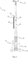
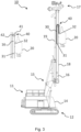
- FIG 1 an example of a special foundation engineering device known from the prior art in the form of a vibrating hammer 1 is shown in a side view, while the Figure 2 shows a front view of the vibratory hammer 1.
- This working machine 1 comprises a carrier device 11, which in turn comprises a mobile undercarriage 12 with crawler track and an upper carriage 14 mounted on the undercarriage 12 so as to be rotatable about a vertical axis of rotation.
- a leader 16 is connected to the upper carriage 14 of the carrier device 11 via a leader kinematics 15.
- the leader kinematics 15 can, as shown in the Figure 1 shown, comprise several base arms, base arm cylinders, and support cylinders, thus forming a parallelogram kinematics by means of which, on the one hand, the leader 16 can be moved from a substantially horizontal transport position into the upright position shown, and, on the other hand, can be tilted relative to the vertical in the upright position.
- the leader 16 can optionally be adjustable relative to the leader kinematics 15 along the leader's longitudinal axis via an adjusting cylinder 19.
- the leader 16 is oriented essentially vertically.
- the leader 16 can also be operated in an inclined position via the leader kinematics 15 (e.g., to drive piles into the ground at an angle or to create an inclined bore).
- the solution according to the invention is therefore particularly (but not exclusively) suitable for operation with a vertically oriented leader 16.
- an attachment tool or attachment 20 is mounted in the longitudinal direction of the leader 16 (ie parallel to the longitudinal axis of the leader 16, which is in the Figure 1 vertically) is adjustably mounted on the leader 16.
- the leader 16 has in particular a leader guide 18 running along the longitudinal direction of the leader 16.
- the attachment 20 can be directly connected to this, wherein the attachment 20 has corresponding guide elements which are connected to the leader guide 18.
- a carriage can be connected to the leader guide 18, ie can be adjustably mounted on the leader 16, wherein the carriage has connecting means for attaching an attachment 20 (e.g. open and/or closed bolt receptacles).
- the leader guide 18 can comprise one or more guide rails extending along the leader 16.
- the attachment 20 is a vibration unit with a clamp for holding and vibrating a pile element (e.g. a sheet pile).
- the leader 16 has a leader head 17 at its upper end and, in the example shown, is designed as a rigid leader. This means that the leader 16 is not telescopic, i.e., its length cannot be adjusted, but rather has a fixed length.
- the attachment 20 is, in particular, hydraulically driven.
- the hydraulic supply to the attachment 20 is via hydraulic hoses that form a power supply line 30.
- the attachment can be fully or partially electrically operated, with the power supply line 30 comprising at least one electrical line for the power supply. It is also conceivable for the power supply line 30 to comprise both at least one hydraulic hose and at least one electrical line.
- the power supply line 30 forms a vertical hose arrangement, with the hydraulic hoses hanging downwards at the sides of the leader 16. This is the typical configuration for generic work machines 1 with a leader 16, particularly for work machines 1 with a rigid leader. As shown in the Figures 1-2 As shown, the power supply line 30 runs between a first connection point 31, which can be located, for example, approximately halfway up the side of the leader 16, and a second connection point 32 on the attachment 20 (or, if present, on the carriage).
- the first connection point 31 can be a bulkhead plate with corresponding hydraulic connections to which the hydraulic hoses of the power supply line 30 are connected. From this bulkhead plate 31, further hydraulic lines can run to the carrier device 11 in order to connect the power supply line 30 and thus the attachment 20 to a hydraulic system of the work machine 1.
- the second connection point 32 on the attachment 20 / carriage (not shown) can also be a bulkhead plate which has corresponding It includes hydraulic connections to which the hydraulic hoses of the power supply line 30 are connected. From this bulkhead plate 32, additional hydraulic lines can run to one or more consumers of the attachment 20.
- a docking station or a quick-release coupling for hydraulic and/or electrical coupling of the attachment 20 can be provided on the attachment 20/slide.
- the power supply line 30 is guided from below to the second connection point 32 during the downward hose unwinding.
- the loop or the hanging part of the hose unwinding thus protrudes into the working area of the work machine 1 and can hinder the work.
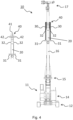
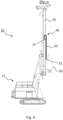
- FIG. 3 and 4 is an embodiment of the work machine 10 according to the invention in a side view ( Fig. 3 ) and in a frontal view ( Fig. 4 ).
- the carrier device 11 is analogous to the one shown in the Figures 1-2 shown example.
- a leader 16 in the form of a rigid leader is also provided, on which an attachment 20 is mounted so as to be adjustable along the longitudinal direction of the leader.
- the same reference numerals as in the Figures 1-2 refer to the same components.
- all statements relating to the working machine 1 of the Figures 1-2 also for the inventive embodiment of the Figures 3-4 (except for the hose unwinding, as explained below). A repeated description is therefore omitted.
- the power supply line 30 is not guided downwards from the first connection point 31 on the leader 16, but upwards (in particular parallel to the leader's longitudinal axis) to a deflection device 40 additionally provided in the work machine 10 according to the invention, by which the power supply line 30 is deflected downwards by approximately 180° toward the attachment 20 and guided from above to the second connection point 32 on the attachment 20 (or alternatively on a carriage).
- the deflection device 40 comprises a deflection carriage 41 mounted on the leader 16 so as to be adjustable along the longitudinal axis of the leader, which carries a deflection roller 42 for the power supply line 30.
- the deflection carriage 41 can comprise multiple deflection pulleys 42.
- the deflection carriage 41 can comprise multiple deflection pulleys 42.
- one or more hydraulic hoses are guided over separate deflection pulleys 42.
- one or more electrical lines are guided over separate deflection pulleys 42.
- hydraulic and electrical hoses or lines can be guided over separate deflection pulleys.
- the deflection carriage 41 can, in particular, be moved along the leader 16 independently of the attachment 20.
- the attachment 20 and the deflection carriage 41 are each adjustable on the leader 16 by means of an actuator (not shown) (e.g., a hydraulic cylinder or cable with a cable winch).
- an actuator e.g., a hydraulic cylinder or cable with a cable winch.
- both are guided by the same leader guide 18.
- a control system (not shown) preferably automatically controls the deflection carriage 41 in such a way that it moves in a fixed relationship, in particular proportionally, to the attachment 20 along the leader 16. If the attachment 20 is moved downwards, for example, the deflection carriage 41 also moves downwards (see the positions of the attachment 20 and the deflection carriage 42 in Figure 5 ).
- the deflection carriage 41 preferably covers a shorter distance along the leader 16 than the attachment 20, so that the distance between the first and second connection points 31, 32 remains constant, ie so that the power supply line 30 is neither stretched nor becomes slack.
- control is set up so that the deflection carriage 41 is moved in synchronization with the attachment 20 in such a way that a constant and, if necessary, predeterminable or adjustable hose pretension results for each position of the attachment 20 on the leader 16.
- the deflection carriage 41 carries two deflection rollers 42 on the sides (see the section of the leader 16 to the left of the overall view, which shows the deflection carriage 41 without power supply lines 30).
- a single power supply line 30 could run on one side of the leader 16, as is the case with the working machine 1 of the Figures 1-2 is the case.
- the first connection point 31 can in turn comprise a bulkhead plate, wherein the hydraulic connections for the hydraulic hoses of the power supply line 30 are arranged on an upper side of the bulkhead plate.
- the second connection point 32 can comprise a bulkhead plate, wherein the hydraulic connections for the hydraulic hoses of the power supply line 30 are also arranged on an upper side of the bulkhead plate.
- the second connection point 32 can comprise a docking station or quick coupling, as mentioned above.
- the power supply line 30 may comprise one or more electrical lines.
- the Figure 5 shows the work machine 10 according to the invention again in a side view, with the attachment 20 in its lowest position on the leader 16.
- the deflection carriage 41 is at its shortest distance from the first connection point 31. Further downward movement is preferably blocked by a mechanical stop and/or by the control system. This can also apply to an uppermost position of the deflection carriage 41.
- deflection slides 41 can be arranged on the leader 16.
- the leader 16 can have any desired structure.
- it can be a lattice boom structure, which can be attached to the boom of a cable excavator, for example.
Landscapes
- Engineering & Computer Science (AREA)
- Life Sciences & Earth Sciences (AREA)
- General Life Sciences & Earth Sciences (AREA)
- Mining & Mineral Resources (AREA)
- Paleontology (AREA)
- Civil Engineering (AREA)
- General Engineering & Computer Science (AREA)
- Structural Engineering (AREA)
- Earth Drilling (AREA)
Applications Claiming Priority (1)
| Application Number | Priority Date | Filing Date | Title |
|---|---|---|---|
| DE102023127266.7A DE102023127266A1 (de) | 2023-10-06 | 2023-10-06 | Arbeitsmaschine mit Mäkler |
Publications (2)
| Publication Number | Publication Date |
|---|---|
| EP4545708A2 true EP4545708A2 (fr) | 2025-04-30 |
| EP4545708A3 EP4545708A3 (fr) | 2025-07-09 |
Family
ID=92843288
Family Applications (1)
| Application Number | Title | Priority Date | Filing Date |
|---|---|---|---|
| EP24200994.2A Pending EP4545708A3 (fr) | 2023-10-06 | 2024-09-18 | Machine de travail avec veaux |
Country Status (2)
| Country | Link |
|---|---|
| EP (1) | EP4545708A3 (fr) |
| DE (1) | DE102023127266A1 (fr) |
Family Cites Families (2)
| Publication number | Priority date | Publication date | Assignee | Title |
|---|---|---|---|---|
| DE3303262A1 (de) * | 1983-02-01 | 1984-08-02 | Fried. Krupp Gmbh, 4300 Essen | Maekler fuer den anbau an den ausleger eines baggers |
| DE20011371U1 (de) * | 2000-06-28 | 2000-09-14 | Bauer Spezialtiefbau Gmbh, 86529 Schrobenhausen | Bauarbeitsgerät |
-
2023
- 2023-10-06 DE DE102023127266.7A patent/DE102023127266A1/de active Pending
-
2024
- 2024-09-18 EP EP24200994.2A patent/EP4545708A3/fr active Pending
Also Published As
| Publication number | Publication date |
|---|---|
| DE102023127266A1 (de) | 2025-04-10 |
| EP4545708A3 (fr) | 2025-07-09 |
Similar Documents
| Publication | Publication Date | Title |
|---|---|---|
| EP3712003B1 (fr) | Système d'approvisionnement en énergie d'un véhicule de flotte | |
| DE69513927T2 (de) | Vorrichtung zur Verstellung des Raupenabstands eines Arbeitsfahrzeuges | |
| DE112012000379B4 (de) | Hydraulikbagger | |
| EP0903443B1 (fr) | Appareil excavateur de creusement de tranchées pour barrettes d'étanchéité | |
| DE69105574T2 (de) | Pfahlramme. | |
| EP1068402A1 (fr) | Appareillage pour l'introduction d'un matériau étranger dans le sol et/ou pour le compactage du sol et méthode de production d'une colonne de matériau dans le sol | |
| EP0897826A2 (fr) | Machine d'installation de ligne catenaire | |
| DE69922668T2 (de) | Auslegeranordnung für eine gesteinbohreinheit | |
| DE102005031076B4 (de) | Pistenpflegefahrzeug mit Seilzugmoment-Kompensation | |
| WO2004110871A1 (fr) | Station de travail et machine d'emballage | |
| DE2821113A1 (de) | Verfahren und vorrichtung zur maschinellen einstellung der neigung einer gesteinsbohrvorrichtung | |
| EP3425123A1 (fr) | Console d'un engin | |
| EP0775080B1 (fr) | Systeme de levage de charges | |
| EP3405649A1 (fr) | Machine de propulsion et de chargement et procédé d'extraction de pierre | |
| DE102021125024B4 (de) | Energieübertragungssystem für ein Schiff | |
| EP4545708A2 (fr) | Machine de travail avec veaux | |
| EP4013564B1 (fr) | Scie à câble | |
| DE69821726T2 (de) | Schlitzwandgreifer mit Korrektur der senkrechten Lage | |
| DE3429214C2 (fr) | ||
| EP2889431B1 (fr) | Machine de travail pour le fonctionnement de benne racleuse | |
| WO2003053821A1 (fr) | Dispositif de treuil a cable dote d'un treuil pivotant | |
| DE10113561B4 (de) | Vorschubvorrichtung für eine Ramm- und/oder Bohrvorrichtung | |
| EP3584370B1 (fr) | Engin de chantier et procédé de fonctionnement d'un engin de chantier | |
| EP1826456A1 (fr) | Courroie d'alimentation | |
| DE19617090A1 (de) | Kran- und Transportvorrichtung mit Laufkatze |
Legal Events
| Date | Code | Title | Description |
|---|---|---|---|
| PUAI | Public reference made under article 153(3) epc to a published international application that has entered the european phase |
Free format text: ORIGINAL CODE: 0009012 |
|
| STAA | Information on the status of an ep patent application or granted ep patent |
Free format text: STATUS: THE APPLICATION HAS BEEN PUBLISHED |
|
| AK | Designated contracting states |
Kind code of ref document: A2 Designated state(s): AL AT BE BG CH CY CZ DE DK EE ES FI FR GB GR HR HU IE IS IT LI LT LU LV MC ME MK MT NL NO PL PT RO RS SE SI SK SM TR |
|
| PUAL | Search report despatched |
Free format text: ORIGINAL CODE: 0009013 |
|
| AK | Designated contracting states |
Kind code of ref document: A3 Designated state(s): AL AT BE BG CH CY CZ DE DK EE ES FI FR GB GR HR HU IE IS IT LI LT LU LV MC ME MK MT NL NO PL PT RO RS SE SI SK SM TR |
|
| RIC1 | Information provided on ipc code assigned before grant |
Ipc: E02D 13/00 20060101ALI20250530BHEP Ipc: E02D 7/02 20060101ALI20250530BHEP Ipc: E02D 7/16 20060101AFI20250530BHEP |
|
| STAA | Information on the status of an ep patent application or granted ep patent |
Free format text: STATUS: REQUEST FOR EXAMINATION WAS MADE |
|
| 17P | Request for examination filed |
Effective date: 20260109 |