EP4545290A1 - Decorative laminate, transfer sheet, decorative member, and mobile body - Google Patents
Decorative laminate, transfer sheet, decorative member, and mobile body Download PDFInfo
- Publication number
- EP4545290A1 EP4545290A1 EP23819898.0A EP23819898A EP4545290A1 EP 4545290 A1 EP4545290 A1 EP 4545290A1 EP 23819898 A EP23819898 A EP 23819898A EP 4545290 A1 EP4545290 A1 EP 4545290A1
- Authority
- EP
- European Patent Office
- Prior art keywords
- layered body
- sce
- layer
- decorative
- light reflectance
- Prior art date
- Legal status (The legal status is an assumption and is not a legal conclusion. Google has not performed a legal analysis and makes no representation as to the accuracy of the status listed.)
- Pending
Links
Images




















Classifications
-
- G—PHYSICS
- G02—OPTICS
- G02B—OPTICAL ELEMENTS, SYSTEMS OR APPARATUS
- G02B5/00—Optical elements other than lenses
- G02B5/32—Holograms used as optical elements
-
- G—PHYSICS
- G02—OPTICS
- G02B—OPTICAL ELEMENTS, SYSTEMS OR APPARATUS
- G02B3/00—Simple or compound lenses
- G02B3/02—Simple or compound lenses with non-spherical faces
- G02B3/08—Simple or compound lenses with non-spherical faces with discontinuous faces, e.g. Fresnel lens
-
- G—PHYSICS
- G02—OPTICS
- G02B—OPTICAL ELEMENTS, SYSTEMS OR APPARATUS
- G02B5/00—Optical elements other than lenses
- G02B5/18—Diffraction gratings
- G02B5/1814—Diffraction gratings structurally combined with one or more further optical elements, e.g. lenses, mirrors, prisms or other diffraction gratings
-
- G—PHYSICS
- G02—OPTICS
- G02B—OPTICAL ELEMENTS, SYSTEMS OR APPARATUS
- G02B5/00—Optical elements other than lenses
- G02B5/18—Diffraction gratings
- G02B5/1861—Reflection gratings characterised by their structure, e.g. step profile, contours of substrate or grooves, pitch variations, materials
Definitions
- the present disclosure relates to a decorative layered body, a transfer sheet, a decorative member, and a mobile body.
- PTL 1 discloses a decorative glass panel including a glass substrate having a curved surface on at least part of one side and a decorative layered body formed on the one side of the glass substrate.
- the decorative layered body includes a relief pattern layer having a relief pattern on its upper surface and a vapor-deposited metal layer formed on the upper surface of the relief pattern layer.
- the above decorative members and decorative layered bodies are required to have good design characteristics, particularly good design characteristics with a sense of three-dimensionality.
- a decorative member having a sense of three-dimensionality rich design expression with a sense of luxury is available.
- One known decorative sheet includes a vapor-deposited metal layer, as disclosed in JP2011-056675A .
- the decorative sheet including the vapor-deposited metal layer light entering from the front side of the decorative sheet is reflected with high intensity from the vapor-deposited metal layer, and the design characteristics of the decorative sheet are thereby improved.
- the vapor-deposited metal layer may crack as the decorative sheet is stretched and therefore whiten or delaminate.
- the whitened or delaminated vapor-deposited metal layer cannot reflect light as desired.
- the decorative sheet including the vapor-deposited metal layer has a problem in terms of formability.
- a first disclosure has been made in consideration of the above problem, and it is an object of the first disclosure to improve the design characteristics of a decorative layered body or a decorative member.
- a second disclosure has been made in consideration of the above problem, and it is an object of the second disclosure to improve the formability of a decorative layered body.
- a decorative layered body of the first disclosure is a decorative layered body including a profiled layer having a profiled surface on which a relief structure is formed,
- the outer total light reflectance (R SCI (O)), the outer diffuse light reflectance (R SCE (O)), and the ratio (R SCI (O) / R SCE (O)) of the outer total light reflectance (R SCI (O)) to the outer diffuse light reflectance (R SCE (O)) may satisfy the following formulas: R SCI O ⁇ 12 % , R SCE O ⁇ 8.5 % , and 1.4 ⁇ R SCI O / R SCE O ⁇ 8 .
- a diffuse light reflectance measured from a side of one surface of the decorative layered body according to JIS Z 8722:2009 in the central region is referred to as central diffuse light reflectance (R SCE (C)), and the ratio (R SCE (C) / R SCE (O)) of the central diffuse light reflectance (R SCE (C)) to the outer diffuse light reflectance (R SCE (O)) may satisfy the following formula: 0.1 ⁇ R SCE C / R SCE O ⁇ 0.9 .
- the ratio (R SCE (C) / R SCE (O)) of the central diffuse light reflectance (R SCE (C)) to the outer diffuse light reflectance (R SCE (O)) may satisfy the following formula: 0.1 ⁇ R SCE C / R SCE O ⁇ 0.7 .
- a decorative layered body of the first disclosure is a decorative layered body including a profiled layer having a profiled surface on which a relief structure is formed,
- the ratio (R SCE (C) / R SCE (O)) of the central diffuse light reflectance (R SCE (C)) to the outer diffuse light reflectance (R SCE (O)) may satisfy the following formula: 0.1 ⁇ R SCE C / R SCE O ⁇ 0.7 .
- a decorative layered body of the first disclosure is a decorative layered body including a profiled layer having a profiled surface on which a relief structure is formed,
- the overall total light reflectance (R SCI (E)), the overall diffuse light reflectance (R SCE (E)), and the ratio (R SCI (E) / R SCE (E)) of the overall total light reflectance (R SCI (E)) to the overall diffuse light reflectance (R SCE (E)) may satisfy the following formulas: R SCI E ⁇ 12 % , R SCE E ⁇ 6 % , and 1.5 ⁇ R SCI E / R SCE E ⁇ 6 .
- the decorative layered body of the first disclosure may further include a transmittance adjusting layer that is disposed outward of the profiled layer on a side of the one surface side of the decorative layered body and adjusts visible light transmittance.
- the decorative layered body of the first disclosure may further include a brightness adjusting layer that covers the profiled surface of the profiled layer, and the brightness adjusting layer may be a reflective layer.
- the decorative layered body of the first disclosure may further include a brightness adjusting layer that covers the profiled surface of the profiled layer, and the brightness adjusting layer may be a refractive index modulation layer having a refractive index different from a refractive index of the profiled surface.
- the decorative layered body of the first disclosure may further include:
- the decorative layered body of the first disclosure may further include a brightness adjusting layer that covers the profiled surface of the profiled layer, and the brightness adjusting layer may contain a high refractive index material.
- the high refractive index material may include titanium oxide, zirconium oxide, or silicon oxide.
- the decorative layered body of the first disclosure may further include a brightness adjusting layer that covers the profiled surface of the profiled layer, and the brightness adjusting layer may contain a pigment and/or a dye.
- the profiled layer may contain a pigment and/or a dye.
- the pigment may be a light reflective pigment or a light absorptive pigment.
- the pigment may include carbon black, an inorganic pigment, a phthalocyanine-based pigment, a quinacridone-based pigment, an isoindolinone-based pigment, a condensed azo-based pigment, a dioxazine-based pigment, an iron oxide pigment, or a composite metal oxide pigment.
- the decorative layered body of the first disclosure may further include a brightness adjusting layer that covers the profiled surface of the profiled layer, and a surface of the brightness adjusting layer that is opposite to a surface facing the profiled layer may have a surface relief corresponding to the relief structure.
- the brightness adjusting layer may have an average thickness less than or equal to 50% of a height of the relief structure.
- the decorative layered body of the first disclosure may further include:
- a transfer sheet of the first disclosure includes:
- the decorative layered body may include a release layer that forms a surface of the decorative layered body that is in contact with the substrate.
- a decorative member of the first disclosure may include:
- a mobile body of the first disclosure includes the above-described decorative layered body.
- a decorative member of the first disclosure is a decorative member including a decorative layered body including a profiled layer
- the outer total light reflectance (R SCI (O)), the outer diffuse light reflectance (R SCE (O)), and the ratio (R SCI (O) / R SCE (O)) of the outer total light reflectance (R SCI (O)) to the outer diffuse light reflectance (R SCE (O)) may satisfy the following formulas: R SCI O ⁇ 12 % , R SCE O ⁇ 8.5 % , and 1.4 ⁇ R SCI O / R SCE O ⁇ 8 .
- a diffuse light reflectance measured from the front surface of the decorative member according to JIS Z 8722:2009 in a region that overlaps the central region of the at least one unit optical element when the decorative layered body is viewed in plan is referred to as central diffuse light reflectance (R SCE (C)), and the ratio (R SCE (C) / R SCE (O)) of the central diffuse light reflectance (R SCE (C)) to the outer diffuse light reflectance (R SCE (O)) may satisfy the following formula: 0.1 ⁇ R SCE C / R SCE O ⁇ 0.9 .
- the ratio (R SCE (C) / R SCE (O)) of the central diffuse light reflectance (R SCE (C)) to the outer diffuse light reflectance (R SCE (O)) may satisfy the following formula: 0.1 ⁇ R SCE C / R SCE O ⁇ 0.7 .
- a decorative member of the first disclosure is a decorative member including a decorative layered body including a profiled layer
- the ratio (R SCE (C) / R SCE (O)) of the central diffuse light reflactance (R SCE (C)) to the outer diffuse light reflectance (R SCE (O)) may satisfy the following formula: 0.1 ⁇ R SCE C / R SCE O ⁇ 0.7 .
- a decorative member of the first disclosure is a decorative member including a decorative layered body including a profiled layer
- the overall total light reflectance (R SCI (E)), the overall diffuse light reflectance (R SCE (E)), and the ratio (R SCI (E) / R SCE (E)) of the overall total light reflectance (R SCI (E)) to the overall diffuse light reflectance (R SCE (E)) may satisfy the following formulas: R SCI E ⁇ 12 % , R SCE E ⁇ 6 % , and 1.5 ⁇ R SCI E / R SCE E ⁇ 6 .
- the decorative member of the first disclosure may further include a molded portion disposed outward of the decorative layered body on the front surface of the decorative member, and the molded portion may adjust visible light transmittance.
- the decorative layered body may further include a transmittance adjusting layer that is disposed outward of the profiled layer on the front surface of the decorative member and that adjusts visible light transmittance.
- the decorative layered body may further include:
- the high refractive index material may include titanium oxide, zirconium oxide, or silicon oxide.
- the profiled layer may contain a pigment and/or a dye.
- the pigment may be a light reflective pigment or a light absorptive pigment.
- the pigment may include carbon black, an inorganic pigment, a phthalocyanine-based pigment, a quinacridone-based pigment, an isoindolinone-based pigment, a condensed azo-based pigment, a dioxazine-based pigment, an iron oxide pigment, or a composite metal oxide pigment.
- the brightness adjusting layer may have an average thickness less than or equal to 50% of a height of the relief structure.
- the decorative layered body may further include:
- a mobile body of the first disclosure includes the above-described decorative member.
- the design characteristics of the decorative layered body or the decorative member can be improved.
- An object of the second disclosure is to improve the formability of a decorative layered body.
- a decorative layered body of the second disclosure includes:
- a value obtained by dividing the width of each of the recessed portions at half the depth of the each of the recessed portions by the average particle diameter of the particles may be 15 or more.
- the second layer may further contain a binder resin.
- a surface of the second layer that is opposite to a surface facing the first layer may have a surface relief corresponding to the relief structure.
- the second layer has an average thickness less than or equal to 50% of a height of the relief structure.
- a decorative layered body of the second disclosure includes
- a value obtained by dividing the width of each of the protruding portions at half the height of the each of the protruding portions by the average particle diameter of the particles may be 15 or more.
- the layer may further contain a binder resin.
- the relief structure may form a group of parallel straight lines or a group of parallel curved lines when the decorative layered body is viewed in plan.
- the relief structure may form an embossed hologram.
- the particles may include a high refractive index material.
- the high refractive index material may include titanium oxide, zirconium oxide, or silicon oxide.
- the particles may include a pigment and/or a dye.
- the pigment may be a light reflective pigment or a light absorptive pigment.
- the particles may include carbon black, an inorganic pigment, an iron oxide pigment, or a composite metal oxide pigment.
- a transfer sheet of the second disclosure includes:
- a decorative member of the second disclosure includes:
- a mobile body of the second disclosure includes the above-described decorative layered body.
- a decorative layered body of the second disclosure includes:
- the absolute difference between the first thickness and the second thickness may be 100 nm or more.
- the absolute difference between maximum and minimum values of the thickness of the brightness adjusting layer on the one of the inclined surfaces may be 100 nm or more.
- a surface of the brightness adjusting layer that is opposite to a surface facing the profiled layer may have a surface relief corresponding to the relief structure.
- the brightness adjusting layer may have an average thickness less than or equal to 50% of a height of the relief structure.
- the decorative layered body of the second disclosure may further include an additional brightness adjusting layer.
- a transfer sheet of the second disclosure includes:
- a decorative member of the second disclosure includes:
- a mobile body of the second disclosure includes the above-described decorative layered body.
- the formability of the decorative layered body can be improved.
- a "transfer sheet” and a member such as a transfer film are not to be distinguished from each other based only on their different designations.
- Figs. 1 to 13F are illustrations explaining the first embodiment.
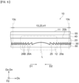
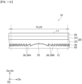
- Figs. 1 and Fig. 2 are illustrations showing an application example of a decorative member 3 including a decorative layered body 10.
- the decorative layered body 10 is formed into a sheet shape and is referred to also as a decorative sheet.
- the decorative layered body 10 displays a design and imparts design characteristics to an article to which the decorative layered body 10 is applied (the decorative member 3 in the example shown in Fig. 1 ).
- the decorative member 3 and/or the decorative layered body 10 according to the first embodiment described below is devised so as to express a sense of three-dimensionality in order to improve the design characteristics. More specifically, with the decorative member 3 and/or the decorative layered body 10, a sense of three-dimensionality as thick as or above the decorative layered body 10 can be expressed to thereby improve the design characteristics.
- the decorative member 3 is used for a mobile body 1.
- the decorative member 3 is installed in a front panel 2 of the mobile body 1.
- the front panel 2 is formed as a front grille.
- a heat exchanger such as a radiator to be air cooled is not installed in some cases. Therefore, the front panel 2 may not be formed as a grille having a large number of holes formed therein.
- the mobile body 1 shown in Fig. 1 is an automobile.
- the mobile body 1 to which the decorative member 3 is applied is not limited to automobiles.
- the decorative member 3 is applicable to other mobile bodies 1 serving as mobile devices. Examples of the other mobile bodies 1 other than automobiles include railroad cars, bogies, ships, airplanes, helicopters, drones, and robots.
- the decorative member 3 and the decorative layered body 10 may be used for interior parts of mobile bodies.
- the decorative member 3 and the decorative layered body 10 are applicable to construction materials such as interior materials, exterior materials, ceiling materials, and floor materials and casings of household electrical appliances, casings of communication devices, and cosmetic containers.
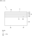
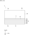
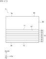
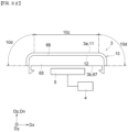
- the decorative member 3 has a front surface 3a and a back surface 3b opposite to the front surface 3a.
- the front surface 3a and the back surface 3b extend along a front surface 66 and a back surface 67, respectively, of a molded portion 65 described later.
- the front surface 3a and the back surface 3b extend two-dimensionally in an X direction Dx and a Y direction Dy orthogonal to the X direction Dx.
- the front surface 3a and the back surface 3b are opposed to each other in a Z direction Dz orthogonal to both the X direction Dx and the Y direction Dy.
- this example is not a limitation, and the front surface 3a and/or the back surface 3b may be a curved surface as shown in Fig. 32 .
- the decorative member 3 includes the decorative layered body 10 and the molded portion 65.
- the molded portion 65 and the decorative layered body 10 are stacked in this order in a direction extending from the back surface 3b of the decorative member 3 to the front surface 3a (the Z direction Dz).
- the decorative member 3 is disposed so as to face a sensor 5.
- the molded portion 65 faces the sensor 5
- the decorative layered body 10 faces an observer 6.
- the decorative layered body 10 has a front surface 11 and a back surface 12.
- the front surface 11 forms the front surface 3a of the decorative member 3.
- the back surface 12 is directed to the back surface 3b side of the decorative member 3 (the molded portion 65 side).
- the front surface 11 and the back surface 12 extend along the front surface 66 of the molded portion 65 described later.
- the front surface 11 and the back surface 12 each extend two dimensionally in the X direction Dx and the Y direction Dy.
- the front surface 11 and the back surface 12 are opposed to each other in the Z direction Dz.
- this example is not a limitation, and the front surface 11 and/or the back surface 12 may be a curved surface as shown in Fig. 32 .
- the molded portion 65 has the front surface 66 and the back surface 67.
- the back surface 67 forms the back surface 3b of the decorative member 3.
- the front surface 66 is directed to the front surface 3a side of the decorative member 3 (the decorative layered body 10 side).
- the front surface 66 and the back surface 67 extend two-dimensionally in the X direction Dx and the Y direction Dy.
- the front surface 66 and the back surface 67 are opposed to each other in the Z direction Dz.
- this example is not a limitation, and the front surface 66 and/or the back surface 67 may be a curved surface as shown in Fig. 32 .
- the molded portion 65 may be formed of any of various materials such as resin materials and glass. No particular limitation is imposed on the resin material forming the molded portion 65. Examples of the resin material forming the molded portion 65 include polymethyl methacrylate (PMMA), polypropylene (PP), polycarbonate (PC), acrylonitrile-butadiene-styrene (ABS), acrylonitrile-(ethylene-propylene-diene)-styrene (AES), and acrylonitrile-styrene-acrylate (ASA).
- PMMA polymethyl methacrylate
- PP polypropylene
- PC polycarbonate
- ABS acrylonitrile-butadiene-styrene
- AES acrylonitrile-(ethylene-propylene-diene)-styrene
- ASA acrylonitrile-styrene-acrylate
- the molded portion 65 may be colored. In this case, any desired color may be imparted to the decorative member 3.
- the molded portion 65 may be transparent or may be opaque. When the molded portion 65 is opaque, at least part of an article to which the decorative member 3 is applied can be hidden by the molded portion 65. For example, in the example shown in Fig. 2 , when the molded portion 65 is opaque, the decorative member 3 can hide the sensor 5.
- transparent means that the visible light transmittance specified as an average of transmittances at different wavelengths measured in the measurement wavelength range of 380 nm to 780 nm using a spectrophotometer ("UV-3100PC" manufactured by Shimadzu Corporation, a product in accordance with JIS K 0115) is 50% or more.
- the average transmittance is preferably 80% or more.
- the decorative member 3 may be disposed so as to face the sensor 5 that uses electromagnetic waves with longer wavelengths than visible light.
- the sensor 5 may monitor the circumstances around the mobile body 1.
- the results of the detection by the sensor 5 may be transmitted to a controller 4 of the mobile body 1.
- the controller 4 may issue an alert based on the results of the detection by the sensor 5 or may control the movement of the mobile body 1.
- the sensor 5 may detect an obstacle etc. in front of the mobile body 1.
- the sensor 5 may be capable of transmitting and receiving electromagnetic waves.
- the sensor 5 may be a millimeter wave radar.
- the millimeter wave radar may use millimeter waves with a wavelength of 1 mm or more and 10 mm or less as the electromagnetic waves.
- the sensor 5 may be a lidar.
- the lidar may use infrared rays as the electromagnetic waves.
- the sensor 5 faces the back surface 3b of the decorative member 3.
- the electromagnetic waves used in the sensor 5 pass through the decorative member 3 in the Z direction Dz.
- the front surface 3a and the back surface 3b serve as an emission surface and an incident surface for the electromagnetic waves.
- the front surface 3a and the back surface 3b are flat surfaces at least in regions facing the sensor 5 in the Z direction Dz.
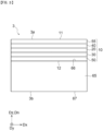
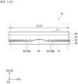
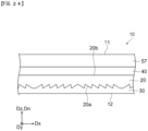
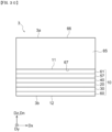
- the decorative layered body 10 includes a profiled layer 20, a brightness adjusting layer 30, and a transmittance adjusting layer 40.
- the profiled layer 20 has a profiled surface 20a having a relief structure 25 formed thereon and a non-profiled surface 20b opposite to the profiled surface 20a.
- the brightness adjusting layer 30 covers the profiled surface 20a.
- the decorative layered body 10 includes at least one unit optical element 13. Each unit optical element 13 reflects, refracts and/or diffracts light incident on the front surface 3a according to the relief structure 25 of the profiled surface 20a.
- the decorative layered body 10 includes a plurality of unit optical elements 13. In this manner, a complicated design formed by a combination of the plurality of unit optical elements 13 can be imparted to the decorative layered body 10.
- the decorative layered body 10 may include additional layers.
- the decorative layered body 10 includes a filling layer 50 and a functional layer 55.
- the filling layer 50, the brightness adjusting layer 30, the profiled layer 20, the transmittance adjusting layer 40, and the functional layer 55 are stacked in this order in the direction from the back surface 12 of the decorative layered body 10 to the front surface 11.
- the functional layer 55 forms the front surface 11 of the decorative layered body 10
- the filling layer 50 forms the back surface 12 of the decorative layered body 10.
- the transmittance adjusting layer 40 is disposed between the front surface 11 of the decorative layered body 10 and the profiled layer 20.
- the profiled layer 20 is disposed between the transmittance adjusting layer 40 and the brightness adjusting layer 30.
- the brightness adjusting layer 30 is disposed between the back surface 12 of the decorative layered body 10 and the profiled layer 20.
- the transmittance adjusting layer 40 may form the front surface 11 of the decorative layered body 10.
- the brightness adjusting layer 30 may form the back surface 12 of the decorative layered body 10.
- the profiled layer 20 includes at least one unit profiled element 23.
- the profiled layer 20 includes a plurality of unit profiled elements 23.
- One unit profiled element 23 corresponds to one unit optical element 13.
- a relief structure 25 is formed in each unit profiled element 23.
- the relief structure 25 can be formed by shaping the profiled layer 20 using a shaping die 100 described later.
- the profiled surface 20a has the relief structure 25
- optical effects (reflection, refraction and/or diffraction) are exerted on light incident on each unit optical element 13 according to the relief structure 25.
- the relief structure 25 is determined such that the parallel light incident on the front surface 11 of the decorative layered body 10 is focused and/or diverged.
- the profiled layer 20 including the unit profiled elements 23 each having the relief structure 25 allows the decorative layered body 10 to express a rich sense of three-dimensionality as large as or above its thickness.
- the profiled layer 20 includes the plurality of unit profiled elements 23, a plurality of unit optical elements 13 can be formed in the decorative layered body 10.
- each relief structure 25 is configured such that the corresponding unit optical element 13 provides an optical effect similar to or corresponding to the optical effect of a convex lens on the light incident on the unit optical element 13.
- the optical effect corresponding to the optical effect similar to that of a convex lens means, for example, an optical effect similar to that of a convex mirror.
- the unit optical element 13 exerts an optical function similar to or corresponding to the optical function of a convex lens. Therefore, the decorative layered body 10 can express a design with a greater sense of depth than the actual depth of the decorative layered body 10 and can express a sense of three-dimensionality. This allows a rich design expression with a sense of luxury.
- each relief structure 25 may be configured such that the corresponding unit optical element 13 provides an optical effect similar to or corresponding to the optical effect of a concave lens on the light incident on the front surface 11 of the decorative layered body 10.
- the decorative layered body 10 can express a design with a greater sense of depth than the actual thickness of the decorative layered body 10 and can express a sense of three-dimensionality. This allows a rich design expression with a sense of luxury.
- the unit profiled elements 23 are not excessively large. This is because, when each unit profiled element 23 is excessively large, the flexibility in the arrangement of the plurality of unit profiled elements 23 in the profiled layer 20 is reduced and the plurality of unit profiled elements 23 may not be arranged as desired.
- the longest length of the unit profiled elements 23 may be 200 mm or less and 100 mm or less.
- the size of each unit profiled element 23 when the decorative layered body 10 is viewed in plan may be 1.0 mm or more and 200 mm or less.
- the plurality of unit profiled elements 23 (the plurality of unit optical elements 13) have the same shape when viewed in plan.
- the plurality of unit profiled elements 23 have a rectangular shape when viewed in plan.
- the plurality of unit profiled elements 23 are regularly arranged.
- the plurality of unit profiled elements 23 are arranged in a square array.
- this example is not a limitation.
- the plurality of unit profiled elements 23 may have different shapes from each other.
- Each unit profiled element 23 may have a shape other than a rectangular shape.
- each unit profiled element 23 may have a polygonal shape such as a triangular, pentagonal, hexagonal, or octagonal shape.
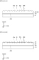
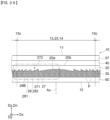
- the profiled surface 20a includes a plurality of inclined surfaces 26A inclined with respect to the normal direction Dn normal to the decorative layered body 10 and a plurality of connection surfaces 26B connecting adjacent ones of the inclined surfaces 26A.
- the number of inclined surfaces 26A included in each unit optical element 13 may be 10 or more, 50 or more, 100 or more, or 200 or more.
- the plurality of inclined surfaces 26A correspond to a plurality of lens surfaces formed by dividing a continuous convex lens surface along planes perpendicular to the thickness direction.
- the connection surfaces 26B correspond to rising surfaces connecting adjacent lens surfaces.
- the decorative member 3 When the decorative member 3 is disposed so as to face the sensor 5, it is necessary for the decorative layered body 10 to allow electromagnetic waves emitted from the sensor 5 to pass through the decorative member 3 with high transmittance. In this case, it is preferable to reduce the thickness of the decorative layered body 10.
- the relief structure 25 of the profiled surface 20a of each unit optical element 13 is a Fresnel lens structure.
- the plurality of inclined surfaces 26A correspond to a plurality of lens surfaces obtained by dividing the lens surface of a curved surface lens such as a spherical lens or cylindrical lens into a plurality of sections along planes perpendicular to the thickness direction (optical axis direction) of the curved surface lens.
- the relief structure 25 is a circular Fresnel lens structure.
- the plurality of inclined surfaces 26A are arranged concentrically, but this is not a limitation.
- the outlines of the plurality of inclined surfaces 26A may be elliptical.
- the extending directions of the major axes of the ellipses in different unit profiled elements 23 may differ from each other.
- the major axis direction of one unit profiled element 23 may be non-parallel or perpendicular to the major axis direction of another unit profiled element 23.
- the relief structure 25 may be a linear Fresnel lens structure.
- the arrangement directions of the inclined surfaces 26A and connection surfaces 26B of different unit profiled elements 23 may differ from each other.
- the arrangement direction of the inclined surfaces 26A and connection surfaces 26B of one linear Fresnel lens structure may be non-parallel or perpendicular to the arrangement direction of the inclined surfaces 26A and connection surfaces 26B of another linear Fresnel lens structure.
- the plurality of inclined surfaces 26A extend so as to surround a reference line L. Therefore, as shown in Fig. 5 , inclined surfaces 26A are present on both sides of the reference line L in the cross-sectional view of the unit optical element 13 taken in the arrangement direction of the inclined surfaces 26A.
- the reference line L coincides with the optical axis of the above-described curved surface lens.
- the reference line L passes through the geometric center of the unit optical element 13 when the decorative layered body 10 is viewed in plan.
- the unit profiled element 23 has the following features. Specifically, as described above, the plurality of inclined surfaces 26A are arranged so as to be directed toward the reference line L. The plurality of inclined surfaces 26A are inclined toward the reference line L. In the example shown in Fig. 5 , the inclined surface 26A on one side of the reference line L (e.g., on the left side in Fig.
- the unit profiled element 23 has the following features as additional features. Specifically, as shown in Figs. 5 and 6 , in the above-described cross section, the standard deviation of the pitches W26 of the inclined surfaces 26A on one side of the reference line L (e.g., the left side in Fig. 5 ) is larger than 5 ⁇ m. In addition, the standard deviation of the heights (the dimension in the Z direction Dz) H26 of the inclined surfaces 26A on one side of the reference line L is 1 ⁇ m or less. The heights H26 may be equal to each other. Moreover, when a plurality of inclined surfaces 26A are also present on the other side of the reference line L (e.g., the right side in Fig.
- the standard deviation of the pitches W26 of the inclined surfaces 26A on the other side of the reference line L is larger than 5 ⁇ m.
- the standard deviation of the heights (the dimension in the Z direction Dz) H26 of the plurality of inclined surfaces 26A on the other side of the reference line L is 1 ⁇ m or less.
- the heights H26 may be equal to each other.
- the pitches W26 decrease as one moves away from the reference line L.
- the unit profiled element 23 has the following additional features. Specifically, in the above-described cross-section, the difference between the maximum and minimum values of the inclined surface angles ⁇ A of the inclined surfaces 26A on one side of the reference line L is larger than 1°. Moreover, as shown in Fig. 5 , when the inclined surfaces 26A are also present on the other side of the reference line L in the above-described cross section, the difference between the maximum and minimum values of the inclined surface angles ⁇ A of the inclined surfaces 26A on the other side of the reference line L is larger than 1°. In the example shown in Figs. 5 and 6 , the inclined surface angles ⁇ A decrease as one moves away from the reference line L on both the one and the other sides of the reference line L.
- the term "inclination surface angle ⁇ A" is the angle of an inclined surface 26A with respect to the normal direction Dn normal to the decorative layered body 10.
- the inclined surfaces 26B extend in the Z direction Dz along the reference line L.
- the relief structure 25 can be appropriately designed according to the function required of the decorative layered body 10 or the design to be expressed by the decorative layered body 10.
- the decorative layered body 10 is required to allow the electromagnetic waves emitted from the sensor 5 to pass through the decorative member 3 with high transmittance. In this case, it is preferable to reduce the thickness of the decorative layered body 10.
- the design expressed by the decorative layered body 10 can differ depending on the intended application of the decorative layered body 10. For example, when the decorative layered body 10 is used as an exterior material for the mobile body 1, it is preferable to prevent the occurrence of prismatic light on the front surface 11 of the decorative layered body 10. However, in some cases, it is preferable to design the decorative layered body 10 such that prismatic light occurs on the front surface 11.
- the height H25 of the relief structure 25 is preferably 0.5 ⁇ m or more, more preferably 1 ⁇ m or more, still more preferably 2 ⁇ m or more, and particularly preferably 3 ⁇ m or more. Moreover, the height H25 of the relief structure 25 is preferably 50 ⁇ m or less, more preferably 15 ⁇ m or less, and still more preferably 10 ⁇ m or less. Therefore, the height H25 of the relief structure 25 may be 0.5 ⁇ m or more and 50 ⁇ m or less. When the height H25 of the relief structure 25 is 1 ⁇ m or more, the visibility of the design displayed by the optical effect can be further improved. As used herein, the "height H25 of the relief structure” means the maximum value of the heights (the dimension in the Z direction Dz) H26 (see Fig. 6 ) of the inclined surfaces 26A or connection surfaces 26B that form the relief structure.
- the height H25 of the relief structure 25 is preferably larger than 1.0 ⁇ m.
- the pitches W26 of the inclined surfaces 26A are preferably 5 ⁇ m or more, more preferably 12 ⁇ m or more, and still more preferably 15 ⁇ m or more. From the viewpoint of achieving a reduction in the size of the unit optical element 13, the pitches W26 of the inclined surfaces 26A are preferably 100 ⁇ m or less, more preferably 50 ⁇ m or less, and still more preferably 20 ⁇ m or less. Therefore, the pitches W26 of the inclined surfaces 26A are preferably 5 ⁇ m or more and 100 ⁇ m or less.
- the height H25 of the relief structure 25 is preferably 0.1 ⁇ m or more, more preferably 0.2 ⁇ m or more, and still more preferably 0.5 ⁇ m or more.
- the height H25 of the relief structure 25 is preferably 10.0 ⁇ m or less, more preferably 6.0 ⁇ m or less, and still more preferably 3.0 ⁇ m or less. Therefore, the height H25 of the relief structure 25 is preferably 0.1 ⁇ m or more and 10.0 ⁇ m or less.
- the pitches W26 of the inclined surfaces 26A are preferably 0.5 ⁇ m or more and preferably 1.0 ⁇ m or more.
- the pitches W26 of the inclined surfaces 26A are preferably less than 10 ⁇ m, more preferably 5 ⁇ m or less, and still more preferably 2 ⁇ m or less. Therefore, when it is desirable to allow prismatic light to occur on the front surface 11 of the decorative layered body 10, the pitches W26 of the inclined surfaces 26A are preferably 0.5 ⁇ m or more and less than 10 ⁇ m.
- the height H25 of the relief structure 25 is preferably 0.2 ⁇ m or more, more preferably 0.5 ⁇ m or more, and still more preferably 1.5 ⁇ m or more.
- the pitch W26 of the relief structure 25 is preferably 0.5 ⁇ m or more, more preferably 2 ⁇ m or more, still more preferably 4 ⁇ m or more, and particularly preferably 8 ⁇ m or more.
- the pitch W26 may vary depending on the distance from the optical axis of the unit optical element 13 (i.e., the reference line L). Specifically, the pitch W26 may decrease as one moves away from the reference line L.
- each unit optical element 13 includes a central region 13a and an outer region 13b.
- the central region 13a is the region through which the reference line L in the unit optical element 13 passes.
- the outer region 13b is the region extending between the central region 13a and an edge portion 13c of the unit optical element 13 in a direction in which the inclined surfaces 26A and the connection surfaces 26B are arranged.
- the reference line L passes through the geometric center of the unit optical element 13 when the decorative layered body 10 is viewed in plan. Therefore, the central region 13a is a region including the geometric center of the unit optical element 13 when the decorative layered body 10 is viewed in plan.
- the outer region 13b of the unit optical element 13 extends between the central region 13a and the edge portion 13c of the unit optical element 13 in the arrangement direction of the plurality of inclined surfaces 26A and the plurality of connection surfaces 26B.
- the pitch W26 in the central region 13a is generally larger than the pitch W26 in the outer region 13b.
- the pitch W26 in the central region 13a is, for example, 20.0 ⁇ m or more and 100.0 ⁇ m or less
- the pitch W26 in the outer region 13b is, for example, 5.0 ⁇ m or more and 20.0 ⁇ m or less.
- the inclined surface angle ⁇ A, the height H25, and the pitch W26 are observed and measured as follows. Specifically, first, the decorative layered body 10 or the decorative member 3 is cut in the stacking direction of the layers forming the decorative layered body 10. Next, the obtained cross section of the decorative layered body 10 is observed using a digital microscope (product name: VHX-8000 series manufactured by KEYENCE CORPORATION), and the inclined surface angle ⁇ A, the height H25, and the pitch W26 are measured.
- a mixture of polymethyl methacrylate (PMMA) and urethane acrylate is used as the material forming the profiled layer 20.
- the material forming the profiled layer 20 contains silicone.
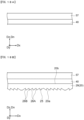
- This profiled layer 20 can be formed by applying a liquid precursor material to a substrate 72, etc. described below, shaping the applied material using a shaping die, and then irradiating the resulting material with UV rays to cure it.
- the precursor material for the profiled layer 20 may be a UV-curable resin that contains, for example, an acrylic resin optionally having a polymerizable unsaturated group and a (meth)acrylic polymerizable monomer or oligomer.
- the term "(meth)acrylic” means either or both of "acrylic” and “methacrylic.”
- the mass ratio of the acrylic resin optionally having a polymerizable unsaturated group / the (meth)acrylic monomer or oligomer in the UV curable resin is preferably 35/65 or more and 95/5 or less and more preferably 70/30 or more and 90/10 or less.
- the thus-formed profiled layer 20 is flexible and has stretchability. Therefore, when the decorative layered body 10 is curved or stretched along the surface of the molded portion 65, the profiled layer 20 can be curved or stretched as desired. In other words, there is little risk that the profiled layer 20 will prevent the decorative layered body 10 from being curbed or stretched.
- thermoplastic resin a vinyl-based resin such as an acrylic resin, acrylonitrile (ABS resin), or polyvinyl chloride
- EB electron beam
- the profiled layer 20 is transparent so that the brightness adjusting layer 30 is visible through the front surface 11.
- the plurality of relief structures 25 in the plurality of unit profiled elements 23 included in the profiled layer 20 are integrally formed without any seams (see Fig. 5 ).
- the brightness adjusting layer 30 is a layer that adjusts the brightness of the light reflected by the decorative layered body 10. By adjusting the brightness of the light reflected by the decorative layered body 10, a rich design with a sense of luxury can be imparted to the decorative layered body 10 more effectively.
- the brightness adjusting layer 30 is provided to adjust the visible light reflectance measured on the front surface 11 side of the decorative layered body 10.
- the brightness adjusting layer 30 covers the profiled surface 20a of the profiled layer 20. In this manner, the visible light reflectance at the reflection interface between the profiled surface 20a and the brightness adjusting layer 30 is adjusted, and the visible light reflectance measured on the front surface 11 side of the decorative layered body 10 is adjusted.
- the surface of the brightness adjusting layer 30 that faces the profiled layer 20 has a surface relief corresponding to the profiled surface 20a. In other words, the brightness adjusting layer 30 has a relief structure corresponding to the relief structure 25 of the profiled layer 20.
- the brightness adjusting layer 30 is a reflective layer.
- the reflective layer 30 covers the profiled surface 20a of the profiled layer 20 to form a reflective interface between the profiled surface 20a and the reflective layer 30.
- the reflective layer 30 improves the visible light reflectance at the reflective interface between the profiled surface 20a and the reflective layer 30, and the brightness of the light reflected by the decorative layered body 10 is thereby adjusted.
- the reflective layer 30 is a metal reflective layer formed by vapor deposition of a metal material, sputtering, coating, etc.
- the reflective layer 30 is formed as a thin film-like layer. The thickness of the reflective layer 30 may be smaller than the heights H26 of the inclined surfaces 26A and the connection surfaces 26B.
- the average thickness of the reflective layer 30 may be 50% or less of the height H25 of the relief structure 25, 25% or less of the height H25 of the relief structure 25, or 10% or less of the height H25 of the relief structure 25.
- the reflective layer 30 having such a thickness has, on the side opposite to the side facing the profiled surface 20a, a surface relief corresponding to the surface relief of the profiled surface 20a without filling in the surface relief of the profiled surface 20a.
- the "thickness of the brightness adjusting layer 30" means the dimension of the brightness adjusting layer 30 in the Z direction Dz (the normal direction Dn normal to the decorative layered body 10).
- the surface relief of the reflective layer 30 is filled with the filling layer 50.
- the reflective layer 30 may be formed so as to fill in the surface relief of the profiled surface 20a.
- the material used for the reflective layer 30 is preferably a material that improves the reflectance of the reflective interface formed by the reflective layer 30 and is more preferably a material that allows electromagnetic waves to pass therethrough.
- the material forming the reflective layer 30 can be, for example, a metal material such as aluminum, indium, tin, or silver.
- the reflective layer 30 may be formed only of one of the metal materials described above.
- the reflective layer 30 is formed by coating, the reflective layer 30 may be formed only of one of the metal materials described above or, if necessary, may be formed using a mixture of any of the metal materials described above and a binder resin.
- the thickness of the reflective layer 30 is such that the reflectance of the reflective interface formed by the reflective layer 30 can be improved.
- the thickness of the reflective layer 30 may be, for example, 0.005 ⁇ m or more.
- the thickness of the reflective layer 30 may be 20 ⁇ m or less. Therefore, the thickness of the reflective layer 30 may be 0.005 ⁇ m or more and 20 ⁇ m or less.
- the thickness of the reflective layer 30 and the thicknesses of the other layers included in the decorative layered body 10 can also be measured by observing a cross-section of the decorative layered body 10 using a digital microscope (product name: VHX-8000 series manufactured by KEYENCE CORPORATION).
- the apparent position of the reflective interface between the profiled layer 20 and the brightness adjusting layer 30 can be perceived so as to be located deeper than the actual position of the reflective interface. In this manner, a rich design expression with a sense of luxury can be achieved, and the design characteristics can be further improved.
- the total light transmittance of the transmittance adjusting layer 40 is set appropriately such that the visible light reflectance measured on the front surface 11 side of the decorative layered body 10 is adjusted to the prescribed reflectance described later. Therefore, it is only necessary that the total light transmittance of the transmittance adjusting layer 40 be less than 100%, and the total light transmittance may be 90% or less, 50% or less, or 10% or less. Of course, the total light transmittance of the transmittance adjusting layer 40 is more than 0%.
- the total light transmittance is the ratio of the total amount of light transmitted through the transmittance adjusting layer 40 to the total amount of light entering the transmittance adjusting layer 40.
- the total light transmittance can be measured using a haze meter (HM-150 manufactured by MURAKAMI COLOR RESEARCH LABORATORY) by a method according to JIS K 7361-1.
- the total light transmittance of the transmittance adjusting layer 40 may be partially changed. For example, the total light transmittance of a part of the transmittance adjusting layer 40 may be 30%, and the total light transmittance of another part may be 10%.
- the transmittance adjusting layer 40 typically contains a pigment.
- the transmittance adjusting layer 40 may contain a dye instead of the pigment or may contain both the pigment and the dye.
- the transmittance adjusting layer 40 absorbs part of the light entering the decorative layered body 10, and the visible light reflectance of the decorative layered body 10 is thereby adjusted.
- the transmittance adjusting layer 40 allows a desired color to be imparted to the decorative layered body 10.
- the material used to form the transmittance adjusting layer 40 can be a resin mixed with a pigment or a dye.
- the transmittance adjusting layer 40 may further contain additives such as a UV absorber and a light stabilizer.
- the resin contained in the transmittance adjusting layer 40 may include a resin composition such as a UV curable resin or an electron beam curable resin.
- the resin contained in the transmittance adjusting layer 40 may be, for example, a non-UV curable acrylic resin.
- the acrylic resin is, for example, a polymer of a (meth)acrylate compound.
- the polymer may be a homopolymer or a copolymer of a (meth)acrylate compound.
- the (meth)acrylate compound include alkyl (meth)acrylates such as methyl (meth)acrylate and ethyl (meth)acrylate, cycloalkyl (meth)acrylates such as cyclohexyl (meth)acrylate, aromatic (meth)acrylates such as such as phenyl (meth)acrylate, and hydroxyalkyl (meth)acrylates such as hydroxyethyl (meth)acrylate, hydroxypropyl (meth)acrylate, and hydroxybutyl (meth)acrylate.
- the acrylic resin is preferably polymethyl methacrylate (PMMA).
- (meth)acrylate compound means either or both of an “acrylate compound” and a “methacrylate compound.”
- the weight average molecular weight (Mw) of the acrylic resin may be, for example, 25000 or more or 50000 or more, from the viewpoint of durability such as heat resistance and abrasion resistance.
- the Mw of the acrylic resin may be, for example, 100000 or less or 80000 or less from the viewpoint of interlayer adhesion.
- the Mw means a value measured by gel permeation chromatography using polystyrene as the standard material and is measured by a method according to JIS K 7252-3:2016.
- the glass transition temperature (Tg) of the acrylic resin may be, for example, 70°C or higher or 85°C or higher from the viewpoint of durability such as heat resistance and abrasion resistance.
- the Tg of the acrylic resin may be, for example, 110°C or lower or 100°C or lower from the viewpoint of interlayer adhesion. Therefore, the Tg of the acrylic resin may be 70°C or higher and 110°C or lower.
- the Tg is the glass transition temperature obtained by differential scanning calorimetry (DSC) according to JIS K 7121:2012.
- the resin contained in the transmittance adjusting layer 40 may be a cured product of an acrylic thermosetting resin.
- the cured product is formed from, for example, the acrylic thermosetting resin and a curing agent.
- the acrylic thermosetting resin include acrylic polyols having two or more hydroxy groups per molecule.
- the acrylic polyol include polymers of (meth)acrylate compounds using at least a hydroxy group-containing monomer such as hydroxyalkyl (meth)acrylate as a raw material monomer.
- the curing agent include isocyanate compounds.
- the transmittance adjusting layer 40 When the transmittance adjusting layer 40 is colored black, the transmittance adjusting layer 40 typically contains a black pigment.
- the transmittance adjusting layer 40 may contain a black dye instead of the black pigment or may contain both the pigment and the dye.
- the black pigment that can be contained in the transmittance adjusting layer 40 include carbon black, titanium black (such as substoichiometric titanium oxides and titanium oxynitride), composite metal oxides, perylene organic black, ceramic black, and bone black.
- the black dye i.e., the black dye contained in the transmittance adjusting layer 40, include azo-based black dyes and nigrosine black dyes.
- the transmittance adjusting layer 40 When the transmittance adjusting layer 40 is colored blue, the transmittance adjusting layer 40 typically contains a blue pigment.
- the transmittance adjusting layer 40 may contain a blue dye instead of the blue pigment or may contain both the pigment and the dye.
- blue pigment that can be contained in the transmittance adjusting layer 40 include copper phthalocyanine-based pigments, anthraquinone-based pigments, cobalt blue, cobalt-based pigments, composite metal oxides, and phthalocyanine-based pigments.
- blue dye examples include methine-based dyes, anthraquinone-based dyes, azo-based dyes, triarylmethane-based dyes, and phthalocyanine-based dyes.
- the transmittance adjusting layer 40 When the transmittance adjusting layer 40 is colored red, the transmittance adjusting layer 40 typically contains a red pigment.
- the transmittance adjusting layer 40 may contain a red dye instead of the red pigment or may contain both the pigment and the dye.
- examples of the red pigment that can be contained in the transmittance adjusting layer 40 include diketopyrrolopyrrole-based pigments, anthraquinone-based pigments, perylene-based pigments, quinacridone-based pigments, titaniumbased complex metal oxides, and iron oxide pigments.
- examples of the red dye that can be contained in the transmittance adjusting layer 40 include azo-based dyes, anthraquinone-based dyes, and perinonebased dyes.
- the transmittance adjusting layer 40 When the transmittance adjusting layer 40 is colored yellow, the transmittance adjusting layer 40 typically contains a yellow pigment.
- the transmittance adjusting layer 40 may contain a yellow dye instead of the yellow pigment or may contain both the pigment and the dye.
- Examples of the yellow pigment that can be contained in the transmittance adjusting layer 40 include isoindolinone-based pigments, anthraquinone-based pigments, complex metal oxides, iron oxide pigments, titanium yellow, and condensed azo-based pigments.
- Examples of the yellow dye that can be contained in the transmittance adjusting layer 40 include azo-based dyes, anthraquinone-based dyes, methine-based dyes, quinophthalone-based dyes, and pyrazolone-based dyes.
- the transmittance adjusting layer 40 When the transmittance adjusting layer 40 is colored green, the transmittance adjusting layer 40 typically contains a green pigment.
- the transmittance adjusting layer 40 may contain a green dye instead of the green pigment or may contain both the pigment and the dye.
- examples of the green pigment that can be contained in the transmittance adjusting layer 40 include phthalocyanine-based pigments, isoindolinone-based pigments, cobalt blue, and cobalt-based pigments.
- examples of the green dye that can be contained in the transmittance adjusting layer 40 include triphenylmethane-based basic dyes and phthalocyanine-based dyes.
- the transmittance adjusting layer 40 When the transmittance adjusting layer 40 is colored purple, the transmittance adjusting layer 40 typically contains a purple pigment.
- the transmittance adjusting layer 40 may contain a purple dye instead of the purple pigment or may contain both the pigment and the dye.
- Examples of the purple pigment that can be contained in the transmittance adjusting layer 40 include quinacridone-based pigments and dioxazine-based pigments.
- Examples of the purple dye that can be contained in the transmittance adjusting layer 40 include azo-based dyes, anthraquinone-based dyes, azine-based dyes, and quinoline-based dyes.
- the transmittance adjusting layer 40 When the transmittance adjusting layer 40 is colored reddish purple, the transmittance adjusting layer 40 typically contains a magenta pigment.
- the transmittance adjusting layer 40 may contain a magenta dye instead of the magenta pigment or may contain both the pigment and the dye.
- Examples of the magenta pigment that can be contained in the transmittance adjusting layer 40 include quinacridone-based pigments.
- Examples of the magenta dye that can be contained in the transmittance adjusting layer 40 include fuchsine and anthraquinone-based dyes.
- the transmittance adjusting layer 40 may contain not only the pigment and dye described above but also a toning pigment or a toning dye.
- the transmittance adjusting layer 40 may further contain any of the above-described blue pigments and dyes as a toning pigment or a toning dye.
- the toning pigment that can be used in this case include, in addition to the above-described blue pigments, various coloring pigments such as the red pigments, yellow pigments, green pigments, magenta pigments, and purple pigments described above.
- examples of the toning dye that can be used in this case include, in addition to the blue dyes described above, various dyes such as the red dyes, green dyes, magenta dyes, yellow dyes, and purple dyes described above.
- the transmittance adjusting layer 40 may contain any of the above-described color pigments and dyes other than the black pigments and dyes so as to be colored black.
- This transmittance adjusting layer 40 is produced by curing a liquid precursor material.
- the precursor material for the transmittance adjusting layer 40 contains the resin and the pigment or dye contained in the transmittance adjusting layer 40 described above.
- the pigment or dye contained in the transmittance adjusting layer 40 has an average particle diameter of 300 nm or less.
- the average particle diameter of the pigment or dye contained in the transmittance adjusting layer 40 is determined by the same method as that for the average particle diameter of particles P described later.
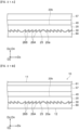
- the transmittance adjusting layer 40 may be formed, for example, as a solid print layer using a printing ink. Alternatively, as shown in Figs. 4 and 5 , the transmittance adjusting layer 40 may be formed so as to include a plurality of unit adjusting elements 41 that adjust the visible light transmittance. In the example shown in Fig. 4 , the plurality of unit adjusting elements 41 have the same shape in plan view. The plurality of unit adjusting elements 41 each have a quadrilateral shape in plan view. The plurality of unit adjusting elements 41 are arranged regularly. In the example shown in Fig. 4 , the plurality of unit adjusting elements 41 are arranged in a square array . In the example shown in Fig.
- the unit adjusting elements 41 have the same shape as the unit profiled elements 23 described above in plan view, and each of the unit adjusting elements 41 is disposed so as to overlap the corresponding one of the unit profiled elements 23 described above.
- the plurality of unit profiled elements 23 may have mutually different shapes.
- the plurality of unit adjusting elements 41 may have a polygonal shape other than the quadrilateral shape.
- the plurality of unit profiled elements 23 may be arranged irregularly.
- the unit adjusting elements 41 may have a shape different from the shape of the unit profiled elements 23 described above in plan view.
- the unit adjusting elements 41 may be arranged so as to overlap each other.
- each unit adjusting element 41 has a size that can be identified by the naked eye.
- the shortest length of each unit adjusting element 41 may be 1.0 mm or more, 10 mm or more, or 20 mm or more.
- each unit adjusting element 41 is not excessively large.
- each unit adjusting element 41 is excessively large, the flexibility in the arrangement of the plurality of unit adjusting elements 41 in the transmittance adjusting layer 40 is low and the plurality of unit adjusting elements 41 may not be arranged as desired.
- the longest length of each unit adjusting element 41 may be 200 mm or less or 100 mm or less.
- the size of each unit adjusting element 41 when the decorative layered body 10 is viewed in plan may be 1.0 mm or more and 200 mm or less.
- the total light transmittance of at least some of the plurality of unit adjusting elements 41 may differ from the total light transmittance of the other unit adjusting elements 41.
- the observer can perceive the Z direction Dz positions of the unit profiled elements 23 overlapping the respective unit adjusting elements 41 such that they differ from each other.
- the resulting sense of three-dimensionality allows the design characteristics to be more effectively improved.
- the thickness of the transmittance adjusting layer 40 is preferably 0.1 ⁇ m or more and 500 ⁇ m or less.
- the filling layer 50 is a flattening layer that fills in the surface relief of the brightness adjusting layer 30.
- the filling layer 50 has a surface relief corresponding to the surface relief of the brightness adjusting layer 30.
- the surface of the brightness adjusting layer 30 that faces the filling layer 50 has a surface relief corresponding to the surface relief of the profiled surface 20a. Therefore, the filling layer 50 has a surface relief corresponding to the surface relief of the profiled surface 20a.
- the filling layer 50 can be a transparent or opaque resin layer. When the filling layer 50 is opaque, the filling layer 50 can hide at least part of an article to which the decorative member 3 is applied. For example, in the example shown in Fig. 2 , when the filling layer 50 is opaque, the decorative member 3 can hide the sensor 5.
- the filling layer 50 may contain a pigments or a dye.
- the pigment contained in the filling layer 50 is preferably, for example, a black pigment such as carbon black, a white pigment such as titanium oxide, or an aluminum-based pigment. When the filling layer 50 contains any of these pigments, the hiding power of the filling layer 50 is improved.
- the filling layer 50 may be formed by vapor-depositing a metal such as aluminum, indium, or tin onto another layer of the decorative layered body 10.
- the filling layer 50 functions also as a bonding layer.
- the bonding layer 50 bonds (adheres, sticks, or thermally fuses) another layer of the decorative layered body 10 to the molded portion 65.
- the material that can be used to form the bonding layer 50 include thermoplastic resins and (meth)acrylate-based copolymers.
- the functional layer 55 is a layer provided with the expectation of providing various functions. Examples of the various functions include a hard coating function, an anti-reflective function, an anti-glare function, an anti-static function, and an anti-staining function.
- the functional layer 55 is a release layer.
- the release layer 55 has releasability that allows the decorative layered body 10 to be easily released from a substrate 72 described later.
- the material that can be used to form the release layer 55 examples include: thermoplastic resins such as acrylic resins, vinyl chloride acetate resins, polyurethane resins, polyolefin resins, polyester resins, epoxy resins, and silicone resins; thermosetting resins obtained by combining these thermoplastic resins with curing agents; UV curable resins; and electron beam curable resins.
- the functional layer 55 forms the front surface 11 of the decorative layered body 10. The other layers of the decorative layered body 10 are observed through the functional layer 55. Therefore, the functional layer 55 is transparent.
- the thickness of the decorative layered body 10 having the structure described above may be 0.005 mm or more, 0.025 mm or more, 0.05 mm or more, 0.1 mm or more, or 0.15 mm or more.
- the thickness of the decorative layered body 10 may be 2 mm or less, 1.0 mm or less, 1 mm or less, 0.75 mm or less, or 0.5 mm or less. Therefore, the thickness of the decorative layered body 10 may be 0.005 mm or more and 2 mm or less.
- the focal length of each unit optical element 13 is preferably 0.5 mm or more and 350 mm or less, more preferably 2 mm or more and 250 mm or less, and still more preferably 5 mm or more and 150 mm or less.
- the focal length of each unit optical element 13 is 0.5 mm or more and 350 mm or less, a sense of three-dimensionality as thick as or above the decorative layered body 10 can be expressed effectively. In this manner, a rich design expression with a sense of luxury can be achieved, and the design characteristics can be further improved.
- the focal length of some of the plurality of unit optical elements 13 may differ from the focal length of the other unit optical elements 13. This allows the observer to perceive the positions of the unit optical elements 13 in the Z direction Dz such that they differ from each other. The resulting sense of three-dimensionality allows the design characteristics to be improved more effectively.
- the apparent thickness of the decorative layered body 10 can be perceived so as to be larger than the actual thickness in an effective manner by adjusting the total light reflectance (R SCI ) and diffuse light reflectance (R SCE ) of the front surface 11 of the decorative layered body 10.
- R SCI total light reflectance
- R SCE diffuse light reflectance
- the apparent position of the reflective interface between the profiled surface 20a and the brightness adjusting layer 30 can be perceived so as to be located deeper than the actual position of the reflective interface. In this manner, a rich design with a sense of luxury can be further effectively imparted to the decorative layered body 10.
- the total light reflectance (R SCI ) and diffuse light reflectance (R SCE ) of the front surface 11 of the decorative layered body 10 in the present embodiment are measured according to JIS Z 8722:2009 under geometric condition c.
- the total light reflectance (R SCI ) and the diffuse light reflectance (R SCE ) are the reflectance Y values (Y of the tristimulus values XYZ) measured by SCI and SCE methods using a spectrocolorimeter according to JIS Z 8722:2009.
- the total light reflectance (R SCI ) and diffuse light reflectance (R SCE ) are measured using a spectrocolorimeter (model CM-700d) manufactured by KONICA MINOLTA, INC.
- the measurement conditions, observation conditions, and measurement/illumination diameters are set as described below.
- the spectrocolorimeter is vertically pressed against the front surface 11 of the decorative layered body 10 placed on a flat surface.
- the range of the measurement wavelength of the spectrocolorimeter is 400 nm to 700 nm, and the measurement wavelength intervals are 10 nm.
- the measurement diameter / illumination diameter are set to ⁇ 3 mm/ ⁇ 6 mm or ⁇ 8 mm/ ⁇ 11 mm.
- the measurement diameter / illumination diameter are selected according to the size of each unit optical element 13.
- the illumination diameter is the diameter of an irradiation area of the spectrocolorimeter
- the measurement diameter is the diameter of a measurement area S of the spectrocolorimeter (see Fig. 8 ).
- the position of the measurement area S relative to the unit optical element 13 when the total light reflectance (R SCI ) and diffuse light reflectance (R SCE ) are measured is set appropriately according to the relation between the size of the unit optical element 13 and the measurement diameter of the spectrocolorimeter.
- the measurement diameter / illumination diameter are selected such that, when the center of the measurement area S is adjusted to coincide with the geometric center of a unit optical element 13, at least 40% of the unit optical element 13 is included in the measurement area S, and then the total light reflectance (R SCI ) and the diffuse light reflectance (R SCE ) are set.
- the measurement diameter the smallest measurement diameter is selected from among selectable measurement diameters.
- the measurement diameter / illumination diameter are set to ⁇ 3 mm/ ⁇ 6 mm.
- the measurement diameter / illumination diameter are set to ⁇ 8 mm/ ⁇ 11 mm.
- the position of the measurement area S relative to a unit optical element 13 is determined such that the center of the measurement area S of the spectrocolorimeter coincides with the geometric center of the unit optical element 13 when the decorative layered body 10 is viewed in plan, and then the total light reflectance (R SCI ) and diffuse light reflectance (R SCE ) are measured.
- the total light reflectance (R SCI ) and diffuse light reflectance (R SCE ) measured in the area including at least 40% of the unit optical element 13 are hereinafter referred to also as “overall total light reflectance (R SCI (E))” and “overall diffuse light reflectance (R SCE (E)),” respectively.
- the measurement diameter / illumination diameter may be set such that one unit optical element 13 is included within the measurement area S, as shown by the chain double-dashed line in Fig. 8 .
- the measurement diameter / illumination diameter are set to the smallest values (i.e., ⁇ 3 mm/ ⁇ 6 mm).
- the total light reflectance (R SCI ) and diffuse light reflectance (R SCE ) are measured in both the outer region 13b and the central region 13a of the unit optical element 13.
- the position of the measurement area S relative to a unit optical element 13 is set such that the measurement area S is located within the outer region 13b when the decorative layered body 10 is viewed in plan, and then the total light reflectance (R SCI ) and the diffuse light reflectance (R SCE ) are measured.
- the total light reflectance (R SCI ) and the diffuse light reflectance (R SCE ) measured in the outer region 13b of the unit optical element 13 as described above are hereinafter referred to also as “outer total light reflectance (R SCI (O))” and “outer diffuse light reflectance (R SCE (O)),” respectively.
- the position of the measurement area S relative to the unit optical element 13 is set such that the measurement area S is located within the central area 13a when the decorative layered body 10 is viewed in plan, and then the total light reflectance (R SCI ) and the diffuse light reflectance (R SCE ) are measured.
- the total light reflectance (R SCI ) and the diffuse light reflectance (R SCE ) measured in the central area 13a of the unit optical element 13 as described above are hereinafter referred to also as “central total light reflectance (R SCI (C))” and “central diffuse light reflectance (R SCE (C)),” respectively.
- the position of the measurement area S relative to the unit optical element 13 is set such that the distance T between the outer edge of the measurement area S and an edge portion 13c of the unit optical element 13 that is closest to the measurement area S is 1 mm, as shown in Fig. 10 .
- the relief structure 25 is irregular in the vicinity of the edge portion 13c of the unit optical element 13, the influence of the disturbance in the reflected light caused by the irregularity in the relief structure 25 on the measurement value can be reduced.
- the spectrocolorimeter is disposed with respect to the decorative layered body 10 such that light Q emitted from the spectrocolorimeter and entering the decorative layered body 10 is incident on (the inclined surfaces 26A or the connection surfaces 26B, as shown by arrows in Figs. 9 and 11 . More specifically, the orientation of the spectrocolorimeter with respect to the decorative layered body 10 is determined as follows.
- the orientation of the spectrocolorimeter with respect to the decorative layered body 10 is determined such that, in a plane defined by a direction normal to the decorative layered body 10 in the region on which the light from the spectrocolorimeter is incident and the arrangement direction of the inclined surfaces 26A and the connection surfaces 26B in this region, the optical axis of the light Q from the spectrocolorimeter is inclined at the same angle as the above-described viewing angle with respect to the normal direction.
- the inventors have found that the apparent thickness of the decorative layered body 10 can be perceived so as to be larger than the actual thickness in an effective manner by adjusting the reflectance of the front surface 11 of the decorative layered body 10 as follows. Specifically, the reflectance of the front surface 11 of the decorative layered body 10 is adjusted such that the overall total light reflectance (R SCI (E)), the overall diffuse light reflectance (R SCE (E)), and the ratio (R SCI (E) / R SCE (E)) of the overall total light reflectance (R SCI (E)) to the overall diffuse light reflectance (R SCE (E)) satisfy the following formulas: R SCI E ⁇ 35 % , R SCE E ⁇ 25 % , and 1.3 ⁇ R SCI E / R SCE E ⁇ 15 .
- the inventors have also found that the apparent thickness of the decorative layered body 10 can be perceived so as to be much larger than the actual thickness by adjusting the reflectance of the front surface 11 of the decorative layered body 10 as follows. Specifically, the reflectance of the front surface 11 of the decorative layered body 10 is adjusted such that the overall total light reflectance (R SCI (E)), the overall diffuse light reflectance (R SCE (E)), and the ratio (R SCI (E) / R SCE (E)) of the overall total light reflectance (R SCI (E)) to the overall diffuse light reflectance (R SCE (E)) satisfy the following formulas: R SCI E ⁇ 12 % , R SCE E ⁇ 6 % , and 1.5 ⁇ R SCI E / R SCE E ⁇ 6 .
- the inventors have also found that the apparent thickness of the decorative layered body 10 can be perceived so as to be larger than the actual thickness in an effective manner by adjusting the reflectance of the front surface 11 of the decorative layered body 10 as follows. Specifically, the reflectance of the front surface 11 of the decorative layered body 10 is adjusted such that the outer total light reflectance (R SCI (O)), the outer diffuse light reflectance (R SCE (O)), and the ratio (R SCI (O) / R SCE (O)) of the outer total light reflectance (R SCI (O)) to the outer diffuse light reflectance (R SCE (O)) satisfy the following formulas: R SCI O ⁇ 45 % , R SCE O ⁇ 40 % , and 1.1 ⁇ R SCI O / R SCE O ⁇ 18 .
- the inventors have also found that the apparent thickness of the decorative layered body 10 can be perceived so as to be much larger than the actual thickness by adjusting the reflectance of the front surface 11 of the decorative layered body 10 as follows. Specifically, the reflectance of the front surface 11 of the decorative layered body 10 is adjusted such that the outer total light reflectance (R SCI (O)), the outer diffuse light reflectance (R SCE (O)), and the ratio (R SCI (O) / R SCE (O)) of the outer total light reflectance (R SCI (O)) to the outer diffuse light reflectance (R SCE (O)) satisfy the following formulas: R SCI O ⁇ 12 , R SCE O ⁇ 8.5 , and 1.4 ⁇ R SCI O / R SCE O ⁇ 8 .
- the inventors have also found that the apparent thickness of the decorative layered body 10 can be perceived so as to be larger than the actual thickness in an effective manner by adjusting the reflectance of the front surface 11 of the decorative layered body 10 as follows. Specifically, the reflectance of the front surface 11 of the decorative layered body 10 is adjusted such that the ratio (R SCE (C) / R SCE (O)) of the central diffuse light reflectance (R SCE (C)) to the outer diffuse light reflectance (R SCE (O)) satisfies the following formula: 0.1 ⁇ R SCE C / R SCE O ⁇ 0.9 .
- the inventors have also found that the apparent thickness of the decorative layered body 10 can be perceived so as to be much larger than the actual thickness by adjusting the reflectance of the front surface 11 of the decorative layered body 10 as follows. Specifically, the reflectance of the front surface 11 of the decorative layered body 10 is adjusted such that the ratio (R SCE (C) / R SCE (O)) of the central diffuse light reflectance (R SCE (C)) to the outer diffuse light reflectance (R SCE (O)) satisfies the following formula: 0.1 ⁇ R SCE C / R SCE O ⁇ 0.7 .
- the total light reflectance (R SCI ) and diffuse light reflectance (R SCE ) of the front surface 11 of the decorative layered body 10 can be adjusted by adjusting the weight ratio (P/V) of the pigment (P) to the resin (V) contained in the brightness adjusting layer 30. More specifically, when the brightness adjusting layer 30 is formed of a colorless transparent resin and a pigment, P/V is preferably 0.2 or more, more preferably 0.5 or more, and still more preferably 0.8 or more. From the viewpoint of the durability of the brightness adjusting layer 30 and its adhesion to other layers, P/V is preferably 2 or less, more preferably 1.5 or less, and still more preferably 1.2 or less. Therefore, P/V may be 0.2 or more and 2 or less.
- the decorative layered body 10 displays a design and imparts design characteristics to the article to which the decorative layered body 10 is applied.
- the decorative layered body 10 can express a sense of three-dimensionality, a rich design with a sense of luxury can be expressed.
- the sense of three-dimensionality of the decorative layered body 10 can be expressed by forming the physical relief structure.
- the thickness of the decorative layered body 10 cannot be increased sufficiently. Due to such restrictions, the design characteristics may not be improved sufficiently. For example, many decorative members, such as decorative members used for vehicle front grilles, are required to be reduced in thickness from the viewpoint of a reduction in weight.
- the thickness of a decorative member designed to allow the transmission of electromagnetic waves such as millimeter waves is set according to the wavelength of the millimeter waves and is subject to restrictions. In addition, from the viewpoint of improving the electromagnetic wave transmittance, it is preferable to reduce the thickness of the decorative layered body.
- the decorative layered body 10 includes the profiled layer 20 having the relief structure 25 described above, and the unit optical elements 13 exhibit the same optical function as a curved surface lens such as a spherical lens or a cylindrical lens or an optical function corresponding to this optical function.
- Fig. 12 is an illustration for explaining the optical function of the unit optical elements 13.
- the reflective interface formed between the profiled layer 20 and the brightness adjusting layer 30 is configured to function as a convex mirror.
- a range A1 reflected in the convex mirror M1 is wider than a specular reflection surface disposed at the same position as the convex mirror M1.
- the range A1 reflected in the convex mirror M1 is the same as a range A1 reflected in a specular reflection surface M3 disposed further away from the observer in the Z direction Dz.
- the observer observing the reflection in the reflective interface feels that the reflective interface serving as the convex mirror M1 is located deeper than the actual position of the reflective interface.
- the unit optical elements 13 can display a design with a sense of depth that is deeper than the actual thickness of the unit optical elements 13. In this manner, the unit optical elements 13 can display a design with a sense of depth that is deeper than its thickness. Therefore, a sense of three-dimensionality that is as thick as or above the unit optical elements 13 can be expressed while the thickness of the unit optical elements 13 is reduced. As a result, a rich design expression with a sense of luxury can be achieved, and the design characteristics can be improved.
- the reflectance of the front surface 11 of the decorative layered body 10 is adjusted as described above. Therefore, the observer observing the reflection in the reflective interface feels that the reflective interface between the profiled layer 20, serving as the convex mirror M1, and the brightness adjusting layer 30 is located deeper than the actual position of the reflective interface.
- FIGs. 13A to 13F are cross-sectional views showing a method for producing a transfer sheet 70 used to transfer the decorative layered body 10 to the molded portion 65.
- a flat substrate 72 is prepared.
- the substrate 72 is a member that is to be removed from the decorative layered body 10 when the decorative layered body 10 is transferred to the molded portion 65.
- the substrate 72 used may be a substrate generally used for a transfer sheet such as a polyester resin film or a polyolefin resin film.
- a parting layer may be formed on one side of the substrate 72. The parting layer has releasability that facilitates the removal of the substrate 72 from the decorative layered body 10.
- thermoplastic resins such as acrylic resins, vinyl chloride acetate resins, polyurethane resins, polyolefin resins, polyester resins, epoxy resins, and silicone resins
- thermosetting resins obtained by combining these thermoplastic resins with curing agents.
- well-known release treatment may be applied to the surface of the substrate 72. In this case also, the substrate 72 can be easily removed from the decorative layered body 10.
- a release layer 55 is formed on the substrate 72.
- the release layer 55 is formed on the parting layer.
- the release layer 55 formed on the substrate 72 allows the substrate 72 to be easily removed from the decorative layered body 10.
- the transmittance adjusting layer 40 is formed on the release layer 55.
- the transmittance adjusting layer 40 may be formed by applying a coating solution for forming the transmittance adjusting layer 40 and curing the coating solution.
- the transmittance adjusting layer 40 may be formed by applying an ink containing any of the pigments and/or dyes described above (e.g., a black ink containing carbon black) by gravure printing.
- a layer 29 of a precursor material for the profiled layer 20 described above is formed on the transmittance adjusting layer 40.
- a shaping die 100 is pressed against the layer 29 to shape the layer 29.
- the shaping die 100 has a surface relief corresponding to the relief structure 25.
- the layer 29 is irradiated with ultraviolet rays to cure the layer 29.
- the shaping die 100 is then detached from the profiled layer 20.
- the shaping die 100 may be detached from the layer 29 before the layer 29 is irradiated with UV rays.
- the reflective layer 30 is formed on the profiled surface 20a of the profiled layer 20 by sputtering, vapor deposition such as vacuum vapor deposition, or coating.
- the filling layer 50 is formed on the reflective layer 30.
- the filling layer 50 serves as a flattening layer that fills in the surface relief of the reflective layer 30.
- the transfer sheet 70 is thereby produced.
- the transfer sheet 70 is placed in a forming mold for molding the molded portion 65.
- a molten resin is introduced between the back surface 12 (i.e., the filling layer 50) of the decorative layered body 10 and the inner surface of the forming mold, and the resin is solidified within the forming mold.
- the molded portion 65 joined to the transfer sheet 70 is formed within the forming mold.
- the substrate 72 is removed from the decorative layered body 10.
- the decorative member 3 (see Fig. 2 ) with the decorative layered body 10 transferred to the molded portion 65 is thereby completed.
- This method for forming the decorative member 3 is known as in-mold decorating.
- the decorative layered body 10 includes the transmittance adjusting layer 40, but this example is not a limitation.
- the decorative layered body 10 need not necessarily include the transmittance adjusting layer 40 so long as the visible light reflectance measured on the front surface 11 side of the decorative layered body 10 is a prescribed reflectance described later.
- the brightness adjusting layer 30 is a reflective layer, but this is not a limitation.
- the brightness adjusting layer 30 may be a refractive index modulation layer.
- the refractive index modulation layer 30 is a layer having a refractive index different from the refractive index of an adjacent layer, and a reflective interface is formed between the refractive index modulation layer 30 and the adjacent layer.
- the refractive index modulation layer 30 has a refractive index different from the refractive index of the profiled layer 20, and a reflective interface is formed between the refractive index modulation layer 30 and the profiled layer 20.
- the refractive index modulation layer 30 covers the relief structure 25 of the profiled layer 20, and a reflective interface is formed between the refractive index modulation layer 30 and the profiled surface 20a. Therefore, the light reflectance of the profiled surface 20a can be improved. In this manner, the brightness of the light reflected by the decorative layered body 10 can be adjusted.
- the refractive index modulation layer 30 contains a high refractive index material.
- the high refractive index material that can be used to form the refractive index modulation layer 30 include titanium oxide, zirconium oxide, silicon oxide, hollow silica, aluminum oxide, zinc oxide, zinc sulfide, and barium titanate.
- the electromagnetic wave transmittance of the refractive index modulation layer 30 can be improved.
- the brightness adjusting layer 30 serving as the refractive index modulation layer will be described later in detail.
- the brightness adjusting layer 30 may be a colored layer.
- the colored layer 30 absorbs part of the light entering the decorative layered body 10, and the visible light reflectance at the reflection interface between the profiled surface 20a and the brightness adjusting layer 30 is thereby adjusted.
- the colored layer 30 can impart a desired color to the decorative layered body 10. In this case, particles formed of a pigment and/or a dye may be dispersed in the brightness adjusting layer 30.
- the brightness adjusting layer 30 serving as the colored layer will be described later in detail.
- the transmittance adjusting layer 40 is produced by applying the ink containing a pigment and/or a dye to the functional layer 55 using gravure printing, but this is not a limitation.
- a preformed sheet-shaped transmittance adjusting layer 40 may be stacked on the functional layer 55 with a bonding layer 56 interposed therebetween, as shown in Fig. 14 .
- the sheet-shaped transmittance adjusting layer 40 can be produced, for example, using a resin material (such as polycarbonate (PC) or acrylic) mixed with a coloring agent.
- the bonding layer 56 can be produced, for example, using an adhesive ink.
- the bonding layer 56 may contain a coloring agent.
- the total light transmittance of the profiled layer 20 may be adjusted.
- the profiled layer 20 may contain particles formed of a pigment and/or a dye, as in the case of the transmittance adjusting layer 40 described above.
- the profiled layer 20 may include a decorative layer that forms the profiled surface 20a and a transmittance adjusting layer 24 that is located at a side of the front surface 11 of the decorative layered body 10 than the decorative layer 22.
- the transmittance adjusting layer 24 in the profiled layer 20 may have a structure similar to that of the transmittance adjusting layer 40 described above.
- the profiled layer 20 as a whole may function as a transmittance adjusting layer.
- particles formed of a pigment and/or a dye may be dispersed over the entire profiled layer 20 (and therefore also in the relief structure 25).
- the profiled layer 20 may have the same total light transmittance as the transmittance adjusting layer 40 described above.
- a sense of three-dimensionality as thick as or above the decorative layered body 10 can be expressed more effectively. Therefore, a rich design expression with a sense of luxury can be achieved, and the design characteristics can be further improved. This modification will be described later in detail.
- the functional layer 55 may have the function of adjusting the visible light transmittance.
- the functional layer 55 may have the same total light transmittance as the transmittance adjusting layer 40 described above.
- a sense of three-dimensionality as thick as or above the decorative layered body 10 can be expressed more effectively. Therefore, a rich design expression with a sense of luxury can be achieved, and the design characteristics can be further improved.
- the decorative layered body 10 may include a substrate layer 57.
- the decorative layered body 10 can be produced by sequentially stacking the other layers of the decorative layered body 10 onto the substrate layer 57.
- the substrate layer 57 may be formed from a film-like member. Any material having appropriate supporting properties can be used as the material forming the substrate layer 57, and examples of the material that can be used include acrylates, ABS, polyvinyl chloride, polymethyl methacrylate, polyethylene terephthalate, polyethylene naphthalate, polycarbonate, polystyrene, cyclic polyolefin, and polypropylene.
- the material forming the substrate layer 57 is preferably an acrylate, ABS, or polyvinyl chloride.
- An acrylate, ABS, polyvinyl chloride, polycarbonate, and polypropylene can be stretched by applying heat.
- the decorative layered body 10 is formed so as to be applicable to a three-dimensional curved surface, there is little risk that the substrate layer 57 will inhibit the shaping of the decorative layered body 10. Moreover, when the decorative layered body 10 is shaped, the risk of the formation of cracks in the substrate layer 57 to cause the substrate layer 57 to whiten is reduced.
- the thickness of the substrate layer 57 is preferably 50 ⁇ m or more.
- the thickness of the substrate layer 57 is preferably 100 ⁇ m or less.
- FIGs. 18A to 18D are cross-sectional views showing the method for producing the decorative layered body 10 shown in Fig. 17 .
- a flat substrate is prepared as the substrate layer 57.
- the transmittance adjusting layer 40 is formed on the substrate layer 57.
- the transmittance adjusting layer 40 is formed using the same method as that shown in Fig. 13B .
- the profiled layer 20 is formed on the transmittance adjusting layer 40.
- the profiled layer 20 is formed using the same method as that shown in Figs. 13C and 13D . Specifically, first, a layer 29 of a precursor material for the profiled layer 20 is formed on the substrate layer 57. Next, the shaping die 100 is pressed against the layer 29, and then the layer 29 is cured. The profiled layer 20 is thereby formed.
- the brightness adjusting layer 30 is formed on the profiled surface 20a of the profiled layer 20.
- the filling layer 50 is formed on the brightness adjusting layer 30.
- the decorative layered body 10 shown in Fig. 17 is thereby produced.
- the decorative layered body 10 is pre-shaped using a preforming die having a shape corresponding to the shape of the front surface 3a of the decorative member 3. Then the pre-shaped decorative layered body 10 is placed in a forming mold for molding the molded portion 65. Next, a molten resin is introduced between the back surface 12 (i.e., the filling layer 50) of the decorative layered body 10 and the inner surface of the forming mold, and the resin is solidified within the forming mold. In this manner, the molded portion 65 joined to the decorative layered body 10 is formed within the forming mold, and the decorative member 3 shown in Fig. 17 is completed.
- the profiled surface 20a of the profiled layer 20 faces the back surface 12 of the decorative layered body 10, but this is not a limitation. As shown in Figs. 19 and 20 , the profiled surface 20a may face the front surface 11 of the decorative layered body 10. In the example shown in Figs. 19 and 20 , a reflective interface is formed between the filling layer 50 and the brightness adjusting layer 30, and the brightness adjusting layer 30 may adjust the visible light reflectance at the reflective interface. When the brightness adjusting layer 30 is a refractive index modulation layer, the refractive index of the brightness adjusting layer 30 may differ from the refractive index of the filling layer 50.
- a reflective interface may be formed between the brightness adjusting layer 30 and the profiled layer 20.
- the brightness adjusting layer 30 may be a refractive index modulation layer, and the refractive index of the brightness adjusting layer 30 may differ from the refractive index of the profiled layer 20.
- the reflective interface is observed through the filling layer 50. Therefore, the filling layer 50 is transparent.
- the brightness adjusting layer 30 can adjust the visible light reflectance measured on the front surface 11 side of the decorative layered body 10.
- the profiled layer 20 may be opaque. When the profiled layer 20 is opaque, the profiled layer 20 can hide at least part of the article to which the decorative member 3 is applied. For example, in the example shown in Figs. 19 and 20 , when the profiled layer 20 is opaque, the decorative member 3 can hide the sensor 5.
- the decorative layered body 10 may have a backer layer 58.
- the backer layer 58 is a layer that reinforces the decorative layered body 10 and allows the decorative layered body 10 to maintain its shape as an integrated body.
- the strength of the decorative layered body 10 is improved. Therefore, as described later, the decorative layered body 10 can be pre-formed before joining to the molded portion 65.
- the backer layer 58, a bonding layer 59, the brightness adjusting layer 30, the profiled layer 20, the transmittance adjusting layer 40, and the functional layer 55 are stacked in this order in the direction from the back surface 12 to the front surface 11 of the decorative layered body 10.
- the backer layer 58 forms the back surface 12 of the decorative layered body 10.
- the material that can be used to form the backer layer examples include ABS resins, polyolefin resins, styrene resins, (meth)acrylic resins, vinyl chloride resins, and polycarbonate resins.
- the polyolefin resin is preferably a polypropylene resin. Of these resins, ABS resins, polypropylene resins, and polycarbonate resins are particularly preferred.
- the material forming the molded portion 65 is an ABS resin
- the material forming the backer layer is preferably an ABS resin.
- the material forming the backer layer is preferably a polypropylene resin.
- the material forming the backer layer is preferably a polycarbonate resin.
- the backer layer 58 may be a film-like member produced using the material for forming the backer layer.
- the thickness of the backer layer 58 is, for example, 0.1 mm or more and 1.0 mm or less.
- the backer layer 58 may be transparent or opaque. When the backer layer 58 is opaque, the backer layer 58 can hide at least part of the article to which the decorative member 3 is applied. For example, in the example shown in Fig. 21 , when the backer layer 58 is opaque, the decorative member 3 can hide the sensor 5.
- the bonding layer 59 bonds the backer layer 58 to another layer of the decorative layered body 10.
- the material forming the bonding layer 59 can be the same material as the material forming the filling layer 50 serving as the bonding layer.
- the functional layer 55 serving as a release layer, the transmittance adjusting layer 40, the profiled layer 20, and the brightness adjusting layer 30 are formed on the substrate 72 by the same method as that shown in Figs. 13A to 13E .
- the bonding layer 59 is formed on the brightness adjusting layer 30.
- the bonding layer 59 is bonded to the backer layer 58.
- the substrate 72 is removed from the decorative layered body 10. The decorative layered body 10 shown in Fig. 21 is thereby produced.
- the decorative layered body 10 is pre-shaped using a preforming die having a shape corresponding to the shape of the front surface 3a of the decorative member 3. Then the pre-shaped decorative layered body 10 is placed in a forming mold for molding the molded portion 65. Next, a molten resin is introduced between the back surface 12 (i.e., the backer layer 58) of the decorative layered body 10 and the inner surface of the forming mold, and the resin is solidified within the forming mold. In this manner, the molded portion 65 joined to the decorative layered body 10 is formed within the forming mold, and the decorative member 3 shown in Fig. 21 is completed. This method of forming the decorative member 3 is known as insert molding.
- the decorative layered body 10 When the decorative layered body 10 includes the substrate layer 57, the decorative layered body 10 need not necessarily include the backer layer 58.
- the brightness adjusting layer 30 fills in the surface relief of the profiled layer 20, the decorative layered body 10 need not necessarily include the filling layer 50.
- the brightness adjusting layer 30, the profiled layer 20, the transmittance adjusting layer 40, and the substrate layer 57 are stacked in this order in the direction from the back surface 12 to the front surface 11 of the decorative layered body 10.
- the substrate layer 57 forms the front surface 11 of the decorative layered body 10
- the brightness adjusting layer 30 forms the back surface 12 of the decorative layered body 10.
- the transmittance adjusting layer 40 and the profiled layer 20 are formed on the substrate layer 57 by the same method as that shown in Figs. 18A to 18C .
- the brightness adjusting layer 30 is formed so as to fill in the surface relief of the profiled surface 20a of the profiled layer 20.
- the decorative layered body 10 shown in Fig. 23 is thereby produced.
- the decorative layered body 10 is pre-shaped using a preforming die having a shape corresponding to the shape of the front surface 3a of the decorative member 3. Then the pre-shaped decorative layered body 10 is placed in a forming mold for molding the molded portion 65. Next, a molten resin is introduced between the back surface 12 (i.e., the brightness adjusting layer 30) of the decorative layered body 10 and the inner surface of the forming mold, and the resin is solidified within the forming mold. In this manner, the molded portion 65 joined to the decorative layered body 10 is formed within the forming mold, and the decorative member 3 shown in Fig. 23 is completed.
- the decorative layered body 10 may include an opaque masking layer 60 as described below.
- the masking layer 60 hides at least part of the article to which the decorative member 3 is applied and at least part of the molded portion 65.
- the masking layer 60 may be formed, for example, of a pigment and/or a dye and a binder resin.
- Preferred examples of the pigment contained in the masking layer 60 include black pigments such as carbon black, white pigments such as titanium oxide, and aluminum-based pigments.
- the masking layer 60 contains any of the above pigments, the hiding power of the masking layer 60 is improved.
- the masking layer 60 may be formed by vapor deposition of a metal such as aluminum, indium, or tin onto another layer of the decorative layered body 10.
- the overall total light reflectance (R SCI (E)), overall diffuse light reflectance (R SCE (E)), outer total light reflectance (R SCI (O)), outer diffuse light reflectance (R SCE (O)), central total light reflectance (R SCI (C)), and central diffuse light reflectance (R SCE (C)) of the decorative layered body 10 can be adjusted.
- the reflectance of the decorative layered body 10 differs depending on whether the masking layer 60 contains a black pigment or a white pigment.
- the decorative layered body 10 may include a bonding layer 61 as described later.
- the bonding layer 61 bonds (adheres, sticks, or thermally fuses) another layer of the decorative layered body 10 to the molded portion 65.
- the decorative layered body 10 may include a scattering layer.
- the scattering layer forms the front surface 11 of the decorative layered body 10 or is located between the front surface 11 and both the profiled layer 20 and the brightness adjusting layer 30.
- the scattering layer scatters visible light reflected by the profiled layer 20 or the brightness adjusting layer 30. Since the light reflected by the profiled layer 20 or the brightness adjusting layer 30 is scattered by the scattering layer, a viewing angle within which the profiled layer 20 or the brightness adjusting layer 30 can be seen from the front surface 11 of the decorative layered body 10 can be widened. Moreover, since the light is scattered by the scattering layer, homogenized light is emitted from the front surface 11 of the decorative layered body 10.
- the scattering layer may contain a binder resin and a light scattering material dispersed in the binder resin.
- the scattering layer can scatter light isotropically by utilizing the difference in refractive index between the binder resin and the light scattering material or by utilizing the reflectance of the light scattering material.
- a well-known material such as a chlorine-based resin, a urethane resin, an acrylic urethane resin, an acrylic resin, a polyester resin, a polyamide resin, a butyral resin, a polystyrene resin, a nitrocellulose resin (cellulose nitrate), or a cellulose acetate resin can be used.
- the light scattering material contained in the scattering layer may be appropriately selected according to the light scattering properties required of the scattering layer.
- the light scattering material include organic particles such as plastic beads and inorganic particles such as silica.
- the plastic beads include melamine beads, acrylic beads, acrylic-styrene beads, polycarbonate beads, polyethylene beads, polystyrene beads, and vinyl chloride beads. Of these, acrylic beads are preferred.
- the light scattering material may be air bubbles.
- the resulting layer can serve as a scattering layer.
- a surface relief may be formed on a surface of the scattering layer that forms the front surface 11.
- the scattering layer need not necessarily contain the light scattering material.
- the surface relief of the front surface 11 of the decorative layered body 10 can also scatter the light reflected by the profiled layer 20 or the brightness adjusting layer 30.
- the decorative layered body 10 may include a UV absorbing layer.
- the UV absorbing layer is a layer containing a UV absorber.
- the UV absorbing layer forms the front surface of the decorative layered body 10.
- the UV absorbing layer is located between the front surface 11 and the transmittance adjusting layer 40.
- the UV absorbing layer is located between the front surface 11 and both the profiled layer 20 and the brightness adjusting layer 30. In this case, the discoloration of the transmittance adjusting layer 40, the profiled layer 20, and the brightness adjusting layer 30 due to UV rays entering the decorative layered body 10 can be suppressed.
- the UV absorbing layer allows visible light to pass therethrough.
- a well-known material can be used as the material forming the UV absorbing layer.
- the UV absorbing layer may be formed using a UV absorber and a binder resin.
- the UV absorber contained in the UV absorbing layer hydroxyphenyltriazine-based UV absorbers, benzotriazole-based UV absorbers, titanium dioxide, etc. can be used.
- the binder resin for forming the UV absorbing layer general-purpose thermoplastic resins, thermosetting resins, and ionizing radiation curable resins can be used.
- the resulting layer can serve as a UV absorbing layer.
- the decorative layered body 10 may further include a design pattern layer.
- a design pattern such as a figure, a design, a picture, a photograph, a character, a mark, a pictogram, a letter, or a number may be formed in the design pattern layer.
- a design expression representing a background may be displayed on the decorative layered body 10.
- a wood grain or marble-like design pattern, a metallic texture, or a geometric pattern may be provided.
- the design pattern provided in the decorative layered body 10 may be a printed layer formed by printing or a transferred layer transferred on the decorative layered body 10.
- the decorative layered body 10 may further include an adhesion improving layer or an adhesive layer for improving the adhesion and bonding between adjacent layers.
- the decorative layered body 10 forms the front surface 3a of the decorative member 3, but this is not a limitation.
- the decorative layered body 10 may form the back surface 3b of the decorative member 3.
- the profiled layer 20 and the brightness adjusting layer 30 may be stacked in this order in the direction from the back surface 3b to the front surface 3a of the decorative layered body 10.
- a reflective interface may be formed between the filling layer 50 and the brightness adjusting layer 30, and the visible light reflectance of the reflective interface may be adjusted by the brightness adjusting layer 30.
- the brightness adjusting layer 30 is a refractive index modulation layer
- the refractive index of the brightness adjusting layer 30 may differ from the refractive index of the filling layer 50.
- a reflective interface may be formed between the brightness adjusting layer 30 and the profiled layer 20.
- the brightness adjusting layer 30 may be a refractive index modulation layer, and the refractive index of the brightness adjusting layer 30 may differ from the refractive index of the profiled layer 20.
- the decorative layered body 10 includes the substrate layer 57, the profiled layer 20, the brightness adjusting layer 30, the filling layer 50, and the transmittance adjusting layer 40.
- the substrate layer 57, the profiled layer 20, the brightness adjusting layer 30, the filling layer 50, and the transmittance adjusting layer 40 are stacked in this order in the direction from the back surface 3b to the front surface 3a of the decorative member 3.
- the transmittance adjusting layer 40 forms the front surface 11 of the decorative layered body 10
- the substrate layer 57 forms the back surface 12 of the decorative layered body 10.
- the transmittance adjusting layer 40 is joined to the back surface 67 of the molded portion 65.
- a bonding layer may be disposed between the transmittance adjusting layer 40 and the molded portion 65. In this case, the bonding layer may form the front surface 11 of the decorative layered body 10.
- the brightness adjusting layer 30 and/or the profiled layer 20 is observed through the molded portion 65 and the filling layer 50. Therefore, the molded portion 65 and the filling layer 50 are transparent.
- the brightness adjusting layer 30 may also be transparent.
- the decorative member 3 shown in Fig. 25 can be produced, for example, as follows. First, as shown in Fig. 26A , the profiled layer 20 is formed on one side of the substrate layer 57. Next, as shown in Fig. 26B , the brightness adjusting layer 30 is formed on the profiled surface 20a of the profiled layer 20. Next, as shown in Fig. 26C , the filling layer 50 is formed on the brightness adjusting layer 30. Next, as shown in Fig. 26D , the transmittance adjusting layer 40 is formed on the filling layer 50. The decorative layered body 10 shown in Fig. 25 is thereby produced.
- the decorative layered body 10 is pre-shaped using a preforming die having a shape corresponding to the shape of the front surface 3a of the decorative member 3. Then the pre-shaped decorative layered body 10 is placed in a forming mold for molding the molded portion 65. Next, a molten resin is introduced between the front surface 11 of the decorative layered body 10 (i.e., the transmittance adjusting layer 40) and the inner surface of the forming mold, and the resin is solidified within the forming mold. The molded portion 65 joined to the decorative layered body 10 is thereby formed within the forming mold, and the decorative member 3 shown in Fig. 25 is completed.
- a molten resin is introduced between the front surface 11 of the decorative layered body 10 (i.e., the transmittance adjusting layer 40) and the inner surface of the forming mold, and the resin is solidified within the forming mold.
- the molded portion 65 joined to the decorative layered body 10 is thereby formed within the forming mold, and the decorative member 3 shown in Fig. 25
- the decorative layered body 10 forms the back surface 3b of the decorative member 3.
- the decorative layered body 10 includes the functional layer 55, the profiled layer 20, the brightness adjusting layer 30, the filling layer 50, the transmittance adjusting layer 40, the bonding layer 59, and the backer layer 58.
- the functional layer 55, the profiled layer 20, the brightness adjusting layer 30, the filling layer 50, the transmittance adjusting layer 40, the bonding layer 59, and the backer layer 58 are stacked in this order in the direction from the back surface 3b to the front surface 3a of the decorative member 3.
- the backer layer 58 forms the front surface 11 of the decorative layered body 10, and the functional layer 55 forms the back surface 12 of the decorative layered body 10.
- the backer layer 58 is joined to the back surface 67 of the molded portion 65.
- a reflective interface may be formed between the filling layer 50 and the brightness adjusting layer 30, and the visible light reflectance of the reflective interface may be adjusted by the brightness adjusting layer 30.
- the brightness adjusting layer 30 is a refractive index modulation layer
- the refractive index of the brightness adjusting layer 30 may differ from the refractive index of the filling layer 50.
- a reflective interface may be formed between the brightness adjusting layer 30 and the profiled layer 20.
- the brightness adjusting layer 30 may be a refractive index modulation layer, and the refractive index of the brightness adjusting layer 30 may differ from the refractive index of the profiled layer 20.
- the brightness adjusting layer 30 and/or the profiled layer 20 is observed through the molded portion 65, the backer layer 58, the bonding layer 59, and the filling layer 50. Therefore, the molded portion 65, the backer layer 58, the bonding layer 59, and the filling layer 50 are transparent.
- the brightness adjusting layer 30 may also be transparent.
- thermoplastic resins and (meth)acrylate ester copolymers can be used as the material forming the transparent bonding layer 59.
- thermoplastic resin examples include acrylic resins, vinyl chloride-vinyl acetate copolymers, polyamide resins, polyester resins, chlorinated polypropylenes, chlorinated rubbers, urethane resins, epoxy resins, and styrene resins. Any of these resins may be used alone, or a combination of two or more may be used.
- the transparent bonding layer 59 may be formed of an OCA (Optical Clear Adhesive).
- the decorative member 3 shown in Fig. 27 can be produced, for example, as follows. First, the functional layer 55 serving as a release layer is formed on the substrate 72 by the same method as that shown in Fig. 13A . Next, as shown in Fig. 28A , the profiled layer 20 is formed on the functional layer 55. Next, the brightness adjusting layer 30 is formed on the profiled surface 20a of the profiled layer 20. Next, as shown in Fig. 28B , the brightness adjusting layer 30 is formed on the profiled surface 20a of the profiled layer 20. Next, as shown in Fig. 28C , the filling layer 50 is formed on the brightness adjusting layer 30. Next, as shown in Fig. 28D , the transmittance adjusting layer 40 is formed on the filling layer 50.
- the bonding layer 59 is formed on the transmittance adjusting layer 40.
- the bonding layer 59 is joined to the backer layer 58.
- the substrate 72 is removed from the decorative layered body 10. The decorative layered body 10 shown in Fig. 27 is thereby produced.
- the decorative layered body 10 is pre-shaped using a preforming die having a shape corresponding to the shape of the front surface 3a of the decorative member 3. Then the pre-formed decorative layered body 10 is placed in a forming mold for molding the molded portion 65. Next, a molten resin is introduced between the front surface 11 of the decorative layered body 10 (i.e., the backer layer 58) and the inner surface of the forming mold, and the resin is solidified within the forming mold. The molded portion 65 joined to the decorative layered body 10 is thereby formed within the forming mold, and the decorative member 3 shown in Fig. 27 is completed.
- a molten resin is introduced between the front surface 11 of the decorative layered body 10 (i.e., the backer layer 58) and the inner surface of the forming mold, and the resin is solidified within the forming mold.
- the molded portion 65 joined to the decorative layered body 10 is thereby formed within the forming mold, and the decorative member 3 shown in Fig. 27 is completed.
- the decorative layered body 10 forms the back surface 3b of the decorative member 3.
- the decorative layered body 10 includes the substrate layer 57, the profiled layer 20, the brightness adjusting layer 30, the filling layer 50, the transmittance adjusting layer 40, the bonding layer 59, and the backer layer 58.
- the substrate layer 57, the profiled layer 20, the brightness adjusting layer 30, the filling layer 50, the transmittance adjusting layer 40, the bonding layer 59, and the backer layer 58 are stacked in this order in the direction from the back surface 3b to the front surface 3a of the decorative member 3.
- the backer layer 58 forms the front surface 11 of the decorative layered body 10, and the substrate layer 57 forms the back surface 12 of the decorative layered body 10.
- the backer layer 58 is joined to the back surface 67 of the molded portion 65.
- a reflective interface may be formed between the filling layer 50 and the brightness adjusting layer 30, and the visible light reflectance at the reflective interface may be adjusted by the brightness adjusting layer 30.
- the brightness adjusting layer 30 is a refractive index modulation layer
- the refractive index of the brightness adjusting layer 30 may differ from the refractive index of the filling layer 50.
- a reflective interface may be formed between the brightness adjusting layer 30 and the profiled layer 20.
- the brightness adjusting layer 30 may be a refractive index modulation layer, and the refractive index of the brightness adjusting layer 30 may differ from the refractive index of the profiled layer 20.
- the brightness adjusting layer 30 and/or the profiled layer 20 is observed through the molded portion 65, the backer layer 58, and the filling layer 50. Therefore, the molded portion 65, the backer layer 58, the bonding layer 59, and the filling layer 50 are transparent.
- the brightness adjusting layer 30 may also be transparent.
- the profiled layer 20 may be transparent or may be opaque.
- the decorative member 3 shown in Fig. 29 can be produced, for example, as follows. First, the profiled layer 20, the brightness adjusting layer 30, the filling layer 50, and the transmittance adjusting layer 40 are stacked on the substrate layer 57 by the same method as that shown in Figs. 26A to Fig. 26D . Next, the bonding layer 59 is formed on the transmittance adjusting layer 40, and the backer layer 58 is joined to the bonding layer 59. The decorative layered body 10 shown in Fig. 29 is thereby produced.
- the decorative layered body 10 forms the back surface 3b of the decorative member 3.
- the decorative layered body 10 includes the masking layer 60, the brightness adjusting layer 30, the profiled layer 20, the transmittance adjusting layer 40, the substrate layer 57, and the bonding layer 61.
- the masking layer 60, the brightness adjusting layer 30, the profiled layer 20, the transmittance adjusting layer 40, the substrate layer 57, and the bonding layer 61 are stacked in this order in the direction from the back surface 3b to the front surface 3a of the decorative member 3.
- the bonding layer 61 forms the front surface 11 of the decorative layered body 10, and the masking layer 60 forms the back surface 12 of the decorative layered body 10.
- the bonding layer 61 is joined to the back surface 67 of the molded portion 65.
- the brightness adjusting layer 30 and/or the profiled layer 20 is observed through the molded portion 65, the bonding layer 61, and the substrate layer 57. Therefore, the molded portion 65, the bonding layer 61, and the substrate layer 57 are transparent.
- the profiled layer 20 may also be transparent.
- the material forming the layer bonding layer 61 the same material as that used to form the transparent bonding layer 59 described above can be used.
- the decorative member 3 shown in Fig. 30 can be produced, for example, as follows. First, the profiled layer 20 and the brightness adjusting layer 30 are stacked on one side of the substrate layer 57 by the same method as that shown in Figs. 18A to 18C . Next, as shown in Fig. 31A , the masking layer 60 is formed on the brightness adjusting layer 30. Next, as shown in Fig. 31B , the bonding layer 61 is formed on the other side of the functional layer 55. After the step shown in Fig. 31B , the bonding layer 61 is joined to the back surface 67 of the molded portion 65. The decorative member 3 shown in Fig. 30 is thereby produced.
- the molded portion 65 may serve also as the functional layer 55 and/or the transmittance adjusting layer 40.
- the decorative layered body 10 need not necessarily include the functional layer 55 and/or the transmittance adjusting layer 40.
- the reflectance of the decorative members 3 shown in Figs. 25 to 31B will be described.
- the present inventors have found that, even when the decorative layered body 10 is observed through the molded portion 65 and other additional layers (not shown) as shown in Figs. 25 to 31B , the apparent thickness of the decorative layered body 10 can be perceived so as to be larger than the actual thickness in an effective manner by adjusting the total light reflectance (R SCI ) and diffuse light reflectance (R SCE )of the front surface 3a of the decorative member 3.
- R SCI total light reflectance
- R SCE diffuse light reflectance
- the inventors further found that, by adjusting the above-described total light reflectance and diffuse light reflectance to prescribed values, the apparent thickness of the decorative layered body 10 can be perceived so as to be much larger than the actual thickness. In this case, the apparent position of the reflective interface in the decorative layered body 10 can be perceived so as to be located deeper than the actual position of the reflective interface
- the total light reflectance (R SCI ) and diffuse light reflectance (R SCE ) of the front surface 3a of the decorative member 3 in the first embodiment are measured in the same manner as that when the total light reflectance (R SCI ) and diffuse light reflectance (R SCE ) of the front surface 11 of the decorative layered body 10 are measured in the examples shown in Figs. 1 to 13F according to JIS Z 8722:2009 using a spectrocolorimeter (model number CM-700d) manufactured by KONICA MINOLTA, INC. under geometric condition c.
- the measurement conditions, the observation conditions, the measurement diameter/illumination diameter, and the measurement wavelength range and measurement wavelength intervals of the spectrocolorimeter during the measurement are also the same as those when the total light reflectance (R SCI ) and diffuse light reflectance (R SCE ) of the front surface 11 of the decorative layered body 10 are measured in the examples shown in Figs. 1 to 13F .
- the total light reflectance (R SCI ) and diffuse light reflectance (R SCE ) are measured by placing the spectrocolorimeter on the front surface 66 of the molded portion 65 such that the spectrocolorimeter is perpendicular to the front surface 11 of the decorative layered body 10.
- the measurement diameter/illumination diameter are selected according to the size of the unit optical elements 13. Moreover, as in the examples shown in Figs. 1 to 13F , the position of the measurement area S relative to a unit optical element 13 when the total light reflectance (R SCI ) and the diffuse light reflectance (R SCE ) are measured is set appropriately according to the relation between the size of the unit optical elements 13 and the measurement diameter of the spectrocolorimeter.
- the total light reflectance (R SCI ) and the diffuse light reflectance (R SCE ) measured in a region that includes at least 40% of a unit optical element 13 (a region on the front surface 3a of the decorative member 3) when the decorative layered body 10 is viewed in plan as shown in Fig. 8 are referred to as "overall total light reflectance (R SCI (E))” and “overall diffuse light reflectance (R SCE (E)),” respectively.
- the total light reflectance (R SCI ) and the diffuse light reflectance (R SCE ) measured in a region that overlaps the outer region 13b of a unit optical element 13 when the decorative layered body 10 is viewed in plan as shown in Fig. 9 are referred to as "outer total light reflectance (R SCI (O))” and “outer diffuse light reflectance (R SCE (O)),” respectively.
- the total light reflectance (R SCI ) and the diffuse light reflectance (R SCE ) measured in a region that overlaps the central area (13a) of a unit optical element (13) when the decorative layered body (10) is viewed in plan as shown in Fig. 9 are referred to as "central total light reflectance (R SCI (C))” and “central diffuse light reflectance (R SCE (C)),” respectively.
- the spectrocolorimeter is disposed with respect to the decorative layered body 10 such that the light Q emitted from the spectrocolorimeter and incident on the decorative layered body 10 enters the inclined surfaces 26A or the connection surfaces 26B, as indicated by the arrows in Figs. 9 and 11 .
- the inventors have found that the apparent thickness of the decorative layered body 10 can be perceived so as to be larger than the actual thickness in an effective manner by adjusting the reflectance of the front surface 3a of the decorative member 3 as follows. Specifically, the reflectance of the front surface 3a of the decorative member 3 is adjusted such that the overall total light reflectance (R SCI (E)), the overall diffuse light reflectance (R SCE (E)), and the ratio (R SCI (E) / R SCE (E)) of the overall total light reflectance (R SCI (E)) to the overall diffuse light reflectance (R SCE (E)) satisfy the following formulas: R SCI E ⁇ 35 % , R SCE E ⁇ 25 % , and 1.3 ⁇ R SCI E / R SCE E ⁇ 15 .
- the inventors have also found that the apparent thickness of the decorative layered body 10 can be perceived so as to be much larger than the actual thickness by adjusting the reflectance of the front surface 3a of the decorative member 3 as follows. Specifically, the reflectance of the front surface 3a of the decorative member 3 is adjusted such that the overall total light reflectance (R SCI (E)), the overall diffuse light reflectance (R SCE (E)), and the ratio (R SCI (E) / R SCE (E)) of the overall total light reflectance (R SCI (E)) to the overall diffuse light reflectance (R SCE (E)) satisfy the following formulas: R SCI E ⁇ 12 % , R SCE E ⁇ 6 % , and 1.5 ⁇ R SCI E / R SCE E ⁇ 6 .
- the inventors have also found that the apparent thickness of the decorative layered body 10 can be perceived so as to be larger than the actual thickness in an effective manner by adjusting the reflectance of the front surface 3a of the decorative member 3 as follows. Specifically, the reflectance of the front surface 3a of the decorative member 3 is adjusted such that the outer total light reflectance (R SCI (O)), the outer diffuse light reflectance (R SCE (O)), and the ratio (R SCI (O) / R SCE (O)) of the outer total light reflectance (R SCI (O)) to the outer diffuse light reflectance (R SCE (O)) satisfy the following formulas: R SCI O ⁇ 45 % , R SCE O ⁇ 40 % , and 1.1 ⁇ R SCI O / R SCE O ⁇ 18 .
- the inventors have also found that the apparent thickness of the decorative layered body 10 can be perceived so as to be much larger than the actual thickness by adjusting the reflectance of the front surface 3a of the decorative member 3 as follows. Specifically, the reflectance of the front surface 3a of the decorative member 3 is adjusted such that the outer total light reflectance (R SCI (O)), the outer diffuse light reflectance (R SCE (O)), and the ratio (R SCI (O) / R SCE (O)) of the outer total light reflectance (R SCI (O)) to the outer diffuse light reflectance (R SCE (O)) satisfy the following formulas: R SCI O ⁇ 12 , R SCE O ⁇ 8.5 , and 1.4 ⁇ R SCI O / R SCE O ⁇ 8 .
- the inventors have also found that the apparent thickness of the decorative layered body 10 can be perceived so as to be larger than the actual thickness in an effective manner by adjusting the reflectance of the front surface 3a of the decorative member 3 as follows. Specifically, the reflectance of the front surface 3a of the decorative member 3 is adjusted such that the ratio (R SCE (C) / R SCE (O)) of the central diffuse light reflectance (R SCE (C)) to the outer diffuse light reflectance (R SCE (O)) satisfies the following formula: 0.1 ⁇ R SCE C / R SCE O ⁇ 0.9 .
- the inventors have also found that the apparent thickness of the decorative layered body 10 can be perceived so as to be much larger than the actual thickness by adjusting the reflectance of the front surface 3a of the decorative member 3 as follows. Specifically, the reflectance of the front surface 3a of the decorative member 3 is adjusted such that the ratio (R SCE (C) / R SCE (O)) of the central diffuse light reflectance (R SCE (C)) to the outer diffuse light reflectance (R SCE (O)) satisfies the following formula: 0.1 ⁇ R SCE C / R SCE O ⁇ 0.7 .
- a decorative layered body 10 was produced in the same manner as that shown in Fig. 5 except that the transmittance adjusting layer 40 was not provided in the decorative layered body 10.
- Each unit optical element 13 had a square shape when the decorative layered body 10 was viewed in plan, and the length of one side of the square unit optical element 13 was 4 mm.
- Aluminum was used as the material forming the brightness adjusting layer 30.
- the measurement diameter / illumination diameter of the spectrocolorimeter were set to ⁇ 8 mm/ ⁇ 11 mm. Then the overall total light reflectance (R SCI (E)) and overall diffuse light reflectance (R SCE (E)) of the front surface 11 of the decorative layered body 10 were measured, and the ratio (R SCI (E) / R SCE (E)) of the overall total light reflectance (R SCI (E)) to the overall diffuse light reflectance (R SCE (E)) was computed.
- R SCI (E) was 79.4%
- R SCE (E) was 68.2%
- R SCI (E) / R SCE (E) was 1.2.
- a decorative layered body 10 was produced in the same manner as in Comparative Example 1-1 except that the transmittance adjusting layer 40 was provided in the decorative layered body 10 as in Fig. 4 .
- the decorative layered body 10 in Comparative Example 1-2 has the same structure as that of the decorative layered body shown in Fig. 5 .
- the total light transmittance of the transmittance adjusting layer 40 was 80%.
- the overall total light reflectance (R SCI (E)) and overall diffuse light reflectance (R SCE (E)) of the front surface 11 of the decorative layered body 10 were measured in the same manner as in Comparative Example 1-1, and the ratio (R SCI (E) / R SCE (E)) of the overall total light reflectance (R SCI (E)) to the overall diffuse light reflectance (R SCE (E)) was computed.
- R SCI (E) was 43.2%
- R SCE (E) was 35.7%
- R SCI (E) / R SCE (E) was 1.2.
- a decorative layered body 10 was produced in the same manner as in Comparative Example 1-2 except that the total light transmittance of the transmittance adjusting layer 40 was 50%.
- the overall total light reflectance (R SCI (E)) and overall diffuse light reflectance (R SCE (E)) of the front surface 11 of the decorative layered body 10 were measured in the same manner as in Comparative Example 1-1, and the ratio (R SCI (E) / R SCE (E)) of the overall total light reflectance (R SCI (E)) to the overall diffuse light reflectance (R SCE (E)) was computed.
- R SCI (E) was 25.0%
- R SCE (E) was 15.1%
- R SCI (E) / R SCE (E) was 1.7.
- a decorative layered body 10 was produced in the same manner as in Comparative Example 1-2 except that the total light transmittance of the transmittance adjusting layer 40 was 30%.
- the overall total light reflectance (R SCI (E)) and overall diffuse light reflectance (R SCE (E)) of the front surface 11 of the decorative layered body 10 were measured in the same manner as in Comparative Example 1-1, and the ratio (R SCI (E) / R SCE (E)) of the overall total light reflectance (R SCI (E)) to the overall diffuse light reflectance (R SCE (E)) was computed.
- R SCI (E) was 9.2%
- R SCE (E) was 4.9%
- R SCI (E) / R SCE (E) was 1.9.
- a decorative layered body 10 was produced in the same manner as in Comparative Example 1-2 except that the total light transmittance of the transmittance adjusting layer 40 was 10%.
- the overall total light reflectance (R SCI (E)) and overall diffuse light reflectance (R SCE (E)) of the front surface 11 of the decorative layered body 10 were measured in the same manner as in Comparative Example 1-1, and the ratio (R SCI (E) / R SCE (E)) of the overall total light reflectance (R SCI (E)) to the overall diffuse light reflectance (R SCE (E)) was computed.
- R SCI (E) was 5.1%
- R SCE (E) was 1.0%
- R SCI (E) / R SCE (E) was 5.1.
- a decorative layered body 10 was produced in the same manner as in Comparative Example 1-2 except that the total light transmittance of the transmittance adjusting layer 40 was 5%.
- the overall total light reflectance (R SCI (E)) and overall diffuse light reflectance (R SCE (E)) of the front surface 11 of the decorative layered body 10 were measured in the same manner as in Comparative Example 1-1, and the ratio (R SCI (E) / R SCE (E)) of the overall total light reflectance (R SCI (E)) to the overall diffuse light reflectance (R SCE (E)) was computed.
- R SCI (E) was 4.4%
- R SCE (E) was 0.5%
- R SCI (E) / R SCE (E) was 8.8.
- a decorative layered body 10 was produced in the same manner as in Comparative Example 1-1 except that titanium oxide was used as the material forming the brightness adjusting layer 30.
- the overall total light reflectance (R SCI (E)) and overall diffuse light reflectance (R SCE (E)) of the front surface 11 of the decorative layered body 10 were measured in the same manner as in Comparative Example 1-1, and the ratio (R SCI (E) / R SCE (E)) of the overall total light reflectance (R SCI (E)) to the overall diffuse light reflectance (R SCE (E)) was computed.
- R SCI (E) was 33.4%
- R SCE (E) was 24.2%
- R SCI (E) / R SCE (E) was 1.4.
- a decorative layered body 10 was produced in the same manner as in Example 1-5 except that the transmittance adjusting layer 40 was provided in the decorative layered body as in Fig. 5 .
- the decorative layered body 10 in Example 1-6 has the same structure as the structure of the decorative layered body shown in Fig. 5 .
- the total light transmittance of the transmittance adjusting layer 40 was 80%.
- the overall total light reflectance (R SCI (E)) and overall diffuse light reflectance (R SCE (E)) of the front surface 11 of the decorative layered body 10 were measured in the same manner as in Comparative Example 1-1, and the ratio (R SCI (E) / R SCE (E)) of the overall total light reflectance (R SCI (E)) to the overall diffuse light reflectance (R SCE (E)) was computed.
- R SCI (E) was 19.0%
- R SCE (E) was 12.7%
- R SCI (E) / R SCE (E) was 1.5.
- a decorative layered body 10 was produced in the same manner as in Example 1-6 except that the total light transmittance of the transmittance adjusting layer 40 was 50%.
- the overall total light reflectance (R SCI (E)) and overall diffuse light reflectance (R SCE (E)) of the front surface 11 of the decorative layered body 10 were measured in the same manner as in Comparative Example 1-1, and the ratio (R SCI (E) / R SCE (E)) of the overall total light reflectance (R SCI (E)) to the overall diffuse light reflectance (R SCE (E)) was computed.
- R SCI (E) was 10.2%
- R SCE (E) was 5.4%
- R SCI (E) / R SCE (E) was 1.9.
- a decorative layered body 10 was produced in the same manner as in Example 1-6 except that the total light transmittance of the transmittance adjusting layer 40 was 30%.
- the overall total light reflectance (R SCI (E)) and overall diffuse light reflectance (R SCE (E)) of the front surface 11 of the decorative layered body 10 were measured in the same manner as in Comparative Example 1-1, and the ratio (R SCI (E) / R SCE (E)) of the overall total light reflectance (R SCI (E)) to the overall diffuse light reflectance (R SCE (E)) was computed.
- R SCI (E) was 6.2%
- R SCE (E) was 1.9%
- R SCI (E) / R SCE (E) was 3.3.
- a decorative layered body 10 was produced in the same manner as in Example 1-6 except that the total light transmittance of the transmittance adjusting layer 40 was 10%.
- the overall total light reflectance (R SCI (E)) and overall diffuse light reflectance (R SCE (E)) of the front surface 11 of the decorative layered body 10 were measured in the same manner as in Comparative Example 1-1, and the ratio (R SCI (E) / R SCE (E)) of the overall total light reflectance (R SCI (E)) to the overall diffuse light reflectance (R SCE (E)) was computed.
- R SCI (E) was 4.5%
- R SCE (E) was 0.4%
- R SCI (E) / R SCE (E) was 11.3.
- a decorative layered body 10 was produced in the same manner as in Example 1-6 except that the total light transmittance of the transmittance adjusting layer 40 was 5%.
- the overall total light reflectance (R SCI (E)) and overall diffuse light reflectance (R SCE (E)) of the front surface 11 of the decorative layered body 10 were measured in the same manner as in Comparative Example 1-1, and the ratio (R SCI (E) / R SCE (E)) of the overall total light reflectance (R SCI (E)) to the overall diffuse light reflectance (R SCE (E)) was computed.
- R SCI (E) was 4.2%
- R SCE (E) was 0.3%
- R SCI (E) / R SCE (E) was 14.0.
- a decorative layered body 10 was produced in the same manner as in Comparative Example 1-1 except that the reflective layer 30 was not provided in the decorative layered body 10 and that particles were dispersed in the profiled layer 20.
- the overall total light reflectance (R SCI (E)) and overall diffuse light reflectance (R SCE (E)) of the front surface 11 of the decorative layered body 10 were measured in the same manner as in Comparative Example 1-1, and the ratio (R SCI (E) / R SCE (E)) of the overall total light reflectance (R SCI (E)) to the overall diffuse light reflectance (R SCE (E)) was computed.
- R SCI (E) was 4.6%
- R SCE (E) was 0.9%
- R SCI (E) / R SCE (E) was 5.1.
- each of the thus-obtained decorative layered bodies 10 in Comparative Examples 1-1 to 1-2 and Examples 1-1 to 1-11 was evaluated.
- the appearance was evaluated by determining the extent to which the glare on the front surface 11 side of the decorative layered body 10 was reduced compared to that in the decorative layered body 10 in Comparative Example 1-1 and by evaluating the sense of depth when the decorative layered body 10 was viewed from the front surface 11 side.
- Table 1 shows the results of the appearance evaluation of the decorative layered bodies 10 in Comparative Examples 1-1 to 1-2 and Examples 1-1 to 1-11.
- C means that the degree of glare is about the same as that in Comparative Example 1-1
- A means that the glare is significantly reduced compared to that in Comparative Example 1-1.
- C means that the perceived depth is about the same as that in Comparative Example 1-1.
- B means that the perceived depth is deeper than that in Comparative Example 1-1, and "A” means that the perceived depth is much deeper than that in Comparative Example 1-1.
- Table 1 also shows, in addition to the results for the Examples and Comparative Examples, the total light reflectance (R SCI ) and diffuse light reflectance (R SCE ) of the surface of a sheet-like substrate with black printing on the surface and having a total light transmittance of 0% and the ratio (R SCI /R SCE ) of the total light reflectance (R SCI ) to the diffuse light reflectance (R SCE ).
- each decorative layered body 10 in which the overall total light reflectance (R SCI (E)) was 12% or less, in which the overall diffuse light reflectance (R SCE (E)) was 6% or less, and in which the ratio (R SCI (E) / R SCE (E)) of the overall total light reflectance (R SCI (E)) to the overall diffuse light reflectance (R SCE (E)) was 1.5 or more and 6.0 or less, the perceived depth was significantly deeper than that in Comparative Example 1-1.
- a decorative layered body 10 was produced in the same manner as that shown in Fig. 5 except that the transmittance adjusting layer 40 was not provided in the decorative layered body 10.
- Each unit optical element 13 had a rhombic shape when the decorative layered body 10 was viewed in plan.
- the length of one of its diagonal lines was 50 mm, and the length of the other diagonal line was 80 mm.
- Aluminum was used as the material forming the brightness adjusting layer 30.
- the measurement diameter / illumination diameter of the spectrocolorimeter were set to ⁇ 3 mm/ ⁇ 6 mm. Then the outer total light reflectance (R SCI (O)) and outer diffuse light reflectance (R SCE (O)) of the front surface 11 of the decorative layered body 10 were measured, and the ratio (R SCI (O) / R SCE (O)) of the outer total light reflectance (R SCI (O)) to the outer diffuse light reflectance (R SCE (O)) was computed.
- the central diffuse light reflectance (R SCE (C)) of the front surface 11 of the decorative layered body 10 was measured, and the ratio (R SCE (C) / R SCE (O)) of the central diffuse light reflectance (R SCE (C)) to the outer diffuse light reflectance (R SCE (O)) was computed.
- R SCI (O) was 97.4%
- R SCE (O) was 100.4%
- R SCI (O) / R SCE (O) was 1.0
- R SCE (C) was 4.3%
- R SCE (C) / R SCE (O) was 0.04.
- a decorative layered body 10 was produced in the same manner as in Comparative Example 2-1 except that the transmittance adjusting layer 40 was provided in the decorative layered body 10 as in Fig. 5 .
- the decorative layered body 10 in Comparative Example 2-2 has the same structure as that of the decorative layered body shown in Fig. 5 .
- the total light transmittance of the transmittance adjusting layer 40 was 80%.
- the outer total light reflectance (R SCI (O)) and outer diffuse light reflectance (R SCE (O)) of the front surface 11 of the decorative layered body 10 were measured in the same manner as in Comparative Example 2-1, and the ratio (R SCI (O) / R SCE (O)) of the outer total light reflectance (R SCI (O)) to the outer diffuse light reflectance (R SCE (O)) was computed.
- the central diffuse light reflectance (R SCE (C)) of the front surface 11 of the decorative layered body 10 was measured in the same manner as in Comparative Example 2-1, and the ratio (R SCE (C) / R SCE (O)) of the central diffuse light reflectance (R SCE (C)) to the outer diffuse light reflectance (R SCE (O)) was computed.
- R SCI (O) was 50.8%
- R SCE (O) was 49.6%
- R SCI (O) / R SCE (O) was 1.0
- R SCE (C) was 2.8%
- R SCE (C) / R SCE (O) was 0.06.
- a decorative layered body 10 was produced in the same manner as in Comparative Example 2-2 except that the total light transmittance of the transmittance adjusting layer 40 was 50%.
- the outer total light reflectance (R SCI (O)) and outer diffuse light reflectance (R SCE (O)) of the front surface 11 of the decorative layered body 10 were measured in the same manner as in Comparative Example 2-1, and the ratio (R SCI (O) / R SCE (O)) of the outer total light reflectance (R SCI (O)) to the outer diffuse light reflectance (R SCE (O)) was computed.
- the central diffuse light reflectance (R SCE (C)) of the front surface 11 of the decorative layered body 10 was measured in the same manner as in Comparative Example 2-1, and the ratio (R SCE (C) / R SCE (O)) of the central diffuse light reflectance (R SCE (C)) to the outer diffuse light reflectance (R SCE (O)) was computed.
- R SCI (O) was 27.2%
- R SCE (O) was 27.3%
- R SCI (O) / R SCE (O) was 1.0
- R SCE (C) was 1.1%
- R SCE (C) / R SCE (O) was 0.04.
- a decorative layered body 10 was produced in the same manner as in Comparative Example 2-2 except that the total light transmittance of the transmittance adjusting layer 40 was 30%.
- the outer total light reflectance (R SCI (O)) and outer diffuse light reflectance (R SCE (O)) of the front surface 11 of the decorative layered body 10 were measured in the same manner as in Comparative Example 2-1, and the ratio (R SCI (O) / R SCE (O)) of the outer total light reflectance (R SCI (O)) to the outer diffuse light reflectance (R SCE (O)) was computed.
- the central diffuse light reflectance (R SCE (C)) of the front surface 11 of the decorative layered body 10 was measured in the same manner as in Comparative Example 2-1, and the ratio (R SCE (C) / R SCE (O)) of the central diffuse light reflectance (R SCE (C)) to the outer diffuse light reflectance (R SCE (O)) was computed.
- R SCI (O) was 10.7%
- R SCE (O) was 7.5%
- R SCI (O) /R SCE (O) was 1.4
- R SCE (C) was 0.5%
- R SCE (C) / R SCE (O) was 0.07.
- a decorative layered body 10 was produced in the same manner as in Comparative Example 2-2 except that the total light transmittance of the transmittance adjusting layer 40 was 10%.
- the outer total light reflectance (R SCI (O)) and outer diffuse light reflectance (R SCE (O)) of the front surface 11 of the decorative layered body 10 were measured in the same manner as in Comparative Example 2-1, and the ratio (R SCI (O) / R SCE (O)) of the outer total light reflectance (R SCI (O)) to the outer diffuse light reflectance (R SCE (O)) was computed.
- the central diffuse light reflectance (R SCE (C)) of the front surface 11 of the decorative layered body 10 was measured in the same manner as in Comparative Example 2-1, and the ratio (R SCE (C) / R SCE (O)) of the central diffuse light reflectance (R SCE (C)) to the outer diffuse light reflectance (R SCE (O)) was computed.
- R SCI (O) was 5.4%
- R SCE (O) was 1.7%
- R SCI (O) / R SCE (O) was 3.2
- R SCE (C) was 0.3%
- R SCE (C) / R SCE (O) was 0.18.
- a decorative layered body 10 was produced in the same manner as in Comparative Example 2-2 except that the total light transmittance of the transmittance adjusting layer 40 was 5%.
- the outer total light reflectance (R SCI (O)) and outer diffuse light reflectance (R SCE (O)) of the front surface 11 of the decorative layered body 10 were measured in the same manner as in Comparative Example 2-1, and the ratio (R SCI (O) / R SCE (O)) of the outer total light reflectance (R SCI (O)) to the outer diffuse light reflectance (R SCE (O)) was computed.
- the central diffuse light reflectance (R SCE (C)) of the front surface 11 of the decorative layered body 10 was measured in the same manner as in Comparative Example 2-1, and the ratio (R SCE (C) / R SCE (O)) of the central diffuse light reflectance (R SCE (C)) to the outer diffuse light reflectance (R SCE (O)) was computed.
- R SCI (O) was 4.4%
- R SCE (O) was 0.5%
- R SCI (O) / R SCE (O) was 8.8,
- R SCE (C) was 0.3%
- R SCE (C) / R SCE (O) was 0.60.
- a decorative layered body 10 was produced in the same manner as in Comparative Example 2-1 except that titanium oxide was used as the material forming the brightness adjusting layer 30.
- the outer total light reflectance (R SCI (O)) and outer diffuse light reflectance (R SCE (O)) of the front surface 11 of the decorative layered body 10 were measured in the same manner as in Comparative Example 2-1, and the ratio (R SCI (O) / R SCE (O)) of the outer total light reflectance (R SCI (O)) to the outer diffuse light reflectance (R SCE (O)) was computed.
- the central diffuse light reflectance (R SCE (C)) of the front surface 11 of the decorative layered body 10 was measured in the same manner as in Comparative Example 2-1, and the ratio (R SCE (C) / R SCE (O)) of the central diffuse light reflectance (R SCE (C)) to the outer diffuse light reflectance (R SCE (O)) was computed.
- R SCI (O) was 40.8%
- R SCE (O) was 37.8%
- R SCI (O) / R SCE (O) was 1.1
- R SCE (C) was 2.7%
- R SCE (C) / R SCE (O) was 0.07.
- a decorative layered body 10 was produced in the same manner as in Example 2-4 except that the transmittance adjusting layer 40 was provided in the decorative layered body as in Fig. 4 .
- the decorative layered body 10 in Example 2-5 has the same structure as that of the decorative layered body shown in Fig. 5 .
- the total light transmittance of the transmittance adjusting layer 40 was 80%.
- the outer total light reflectance (R SCI (O)) and outer diffuse light reflectance (R SCE (O)) of the front surface 11 of the decorative layered body 10 were measured in the same manner as in Comparative Example 2-1, and the ratio (R SCI (O) / R SCE (O)) of the outer total light reflectance (R SCI (O)) to the outer diffuse light reflectance (R SCE (O)) was computed.
- the central diffuse light reflectance (R SCE (C)) of the front surface 11 of the decorative layered body 10 was measured in the same manner as in Comparative Example 2-1, and the ratio (R SCE (C) / R SCE (O)) of the central diffuse light reflectance (R SCE (C)) to the outer diffuse light reflectance (R SCE (O)) was computed.
- R SCI (O) was 22.6%
- R SCE (O) was 19.0%
- R SCI (O) / R SCE (O) was 1.2
- R SCE (C) was 1.6%
- R SCE (C) / R SCE (O) was 0.08.
- a decorative layered body 10 was produced in the same manner as in Example 2-5 except that the total light transmittance of the transmittance adjusting layer 40 was 50%.
- the outer total light reflectance (R SCI (O)) and outer diffuse light reflectance (R SCE (O)) of the front surface 11 of the decorative layered body 10 were measured in the same manner as in Comparative Example 2-1, and the ratio (R SCI (O) / R SCE (O)) of the outer total light reflectance (R SCI (O)) to the outer diffuse light reflectance (R SCE (O)) was computed.
- the central diffuse light reflectance (R SCE (C)) of the front surface 11 of the decorative layered body 10 was measured in the same manner as in Comparative Example 2-1, and the ratio (R SCE (C) / R SCE (O)) of the central diffuse light reflectance (R SCE (C)) to the outer diffuse light reflectance (R SCE (O)) was computed.
- R SCI (O) was 11.5%
- R SCE (O) was 8.2%
- R SCI (O) /R SCE (O) was 1.4
- R SCE (C) was 0.9%
- R SCE (C) / R SCE (O) was 0.11.
- a decorative layered body 10 was produced in the same manner as in Example 2-5 except that the total light transmittance of the transmittance adjusting layer 40 was 30%.
- the outer total light reflectance (R SCI (O)) and outer diffuse light reflectance (R SCE (O)) of the front surface 11 of the decorative layered body 10 were measured in the same manner as in Comparative Example 2-1, and the ratio (R SCI (O) / R SCE (O)) of the outer total light reflectance (R SCI (O)) to the outer diffuse light reflectance (R SCE (O)) was computed.
- the central diffuse light reflectance (R SCE (C)) of the front surface 11 of the decorative layered body 10 was measured in the same manner as in Comparative Example 2-1, and the ratio (R SCE (C) / R SCE (O)) of the central diffuse light reflectance (R SCE (C)) to the outer diffuse light reflectance (R SCE (O)) was computed.
- R SCI (O) was 6.4%
- R SCE (O) was 2.6%
- R SCI (O) / R SCE (O) was 2.5
- R SCE (C) was 0.4%
- R SCE (C) / R SCE (O) was 0.15.
- a decorative layered body 10 was produced in the same manner as in Example 2-5 except that the total light transmittance of the transmittance adjusting layer 40 was 10%.
- the outer total light reflectance (R SCI (O)) and outer diffuse light reflectance (R SCE (O)) of the front surface 11 of the decorative layered body 10 were measured in the same manner as in Comparative Example 2-1, and the ratio (R SCI (O) / R SCE (O)) of the outer total light reflectance (R SCI (O)) to the outer diffuse light reflectance (R SCE (O)) was computed.
- the central diffuse light reflectance (R SCE (C)) of the front surface 11 of the decorative layered body 10 was measured in the same manner as in Comparative Example 2-1, and the ratio (R SCE (C) / R SCE (O)) of the central diffuse light reflectance (R SCE (C)) to the outer diffuse light reflectance (R SCE (O)) was computed.
- R SCI (O) was 4.6%
- R SCE (O) was 0.6%
- R SCI (O) / R SCE (O) was 7.7
- R SCE (C) was 0.3%
- R SCE (C) / R SCE (O) was 0.50.
- a decorative layered body 10 was produced in the same manner as in Example 2-5 except that the total light transmittance of the transmittance adjusting layer 40 was 5%.
- the outer total light reflectance (R SCI (O)) and outer diffuse light reflectance (R SCE (O)) of the front surface 11 of the decorative layered body 10 were measured in the same manner as in Comparative Example 2-1, and the ratio (R SCI (O) / R SCE (O)) of the outer total light reflectance (R SCI (O)) to the outer diffuse light reflectance (R SCE (O)) was computed.
- the central diffuse light reflectance (R SCE (C)) of the front surface 11 of the decorative layered body 10 was measured in the same manner as in Comparative Example 2-1, and the ratio (R SCE (C) / R SCE (O)) of the central diffuse light reflectance (R SCE (C)) to the outer diffuse light reflectance (R SCE (O)) was computed.
- R SCI (O) was 4.2%
- R SCE (O) was 0.3%
- R SCI (O) / R SCE (O) was 16.6,
- R SCE (C) was 0.2%
- R SCE (C) / R SCE (O) was 0.84.
- a decorative layered body 10 was produced in the same manner as in Comparative Example 2-1 except that the reflective layer 30 was not provided in the decorative layered body 10 and that particles were dispersed in the profiled layer 20.
- the outer total light reflectance (R SCI (O)) and outer diffuse light reflectance (R SCE (O)) of the front surface 11 of the decorative layered body 10 were measured in the same manner as in Comparative Example 2-1, and the ratio (R SCI (O) / R SCE (O)) of the outer total light reflectance (R SCI (O)) to the outer diffuse light reflectance (R SCE (O)) was computed.
- the central diffuse light reflectance (R SCE (C)) of the front surface 11 of the decorative layered body 10 was measured in the same manner as in Comparative Example 2-1, and the ratio (R SCE (C) / R SCE (O)) of the central diffuse light reflectance (R SCE (C)) to the outer diffuse light reflectance (R SCE (O)) was computed.
- R SCI (O) was 4.9%
- R SCE (O) was 1.0%
- R SCI (O) / R SCE (O) was 4.7
- R SCE (C) was 0.7%
- R SCE (C) / R SCE (O) was 0.67.
- Table 2 shows the results of the appearance evaluation of the decorative layered bodies 10 in Comparative Examples 2-1 to 2-3 and Examples 2-1 to 2-10.
- C means that the degree of glare is about the same as that in Comparative Example 2-1
- A means that the glare is significantly reduced compared to that in Comparative Example 2-1.
- C means that the perceived depth is about the same as that in Comparative Example 2-1.
- B means that the perceived depth is deeper than that in Comparative Example 2-1, and "A” means that the perceived depth is much deeper than that in Comparative Example 2-1.
- Table 2 also shows, in addition to the results for the Examples and Comparative Examples, the total light reflectance (R SCI ) and diffuse light reflectance (R SCE ) of the surface of a sheet-like substrate with black printing on the surface and having a total light transmittance of 0% and the ratio (R SCI /R SCE ) of the total light reflectance (R SCI ) to the diffuse light reflectance (R SCE ).
- a decorative member 3 and a decorative layered body 10 shown in Fig. 32 differ from the decorative member 3 and decorative layered body 10 described above mainly in that it is not always necessary for the reflectance of the front surface to meet the requirements for the total light reflectance (R SCI ) and diffuse light reflectance (R SCE ) described above.
- the rest of the structure is substantially the same as that of the decorative member 3 and the decorative layered body 10 shown in Fig. 17 .
- the reflectance of the front surface may meet the requirements for the total light reflectance (R SCI ) and the diffuse light reflectance (R SCE ).
- the decorative member 3 includes the decorative layered body 10 and the molded portion 65.
- the decorative layered body 10 has been shaped, and each layer of the decorative layered body 10 has a flat portion 10c and a curved portion 10d.
- the curved portion 10d is connected circumferentially to the circumferential edge of the flat portion 10c.
- the flat portion 10c extends two-dimensionally in the X direction (Dx) and Y direction (Dy).
- the flat portion 10c and the curved portion 10d form a recessed portion that receives part of the molded portion 65.
- the shape of the decorative layered body 10 in the decorative member 3 is not limited to the above shape.
- the decorative layered body 10 may be flat, as shown in Fig. 2 .
- a decorative layered body 10 includes the profiled layer 20 and the brightness adjusting layer 30.
- the decorative layered body 10 further includes the masking layer 60, the filling layer 50, the transmittance adjusting layer 40, and the substrate layer 57.
- the masking layer 60, the filling layer 50, the brightness adjusting layer 30, the profiled layer 20, the transmittance adjusting layer 40, and the substrate layer 57 are stacked in this order in the direction from the back surface 12 of the decorative layered body 10 to the front surface 11.
- the masking layer 60 forms the back surface 12 of the decorative layered body 10
- the substrate layer 57 forms the front surface 11 of the decorative layered body 10.
- Fig. 34 is an enlarged view of a portion surrounded by a chain double-dashed line in the cross-sectional view of the decorative layered body 10 shown in Fig. 33 .
- the illustration of particles P described later is omitted for the sake of clarity.
- the fine relief structure 25 is formed in the profiled layer 20.
- the profiled layer 20 has a relief surface formed by the relief structure 25.
- the relief structure 25 includes a plurality of protruding portions 27 and a plurality of recessed portions 28 formed between the plurality of protruding portions 27.
- the apexes 271 of adjacent protruding portions 27 form openings 282 of the recessed portions 28.
- each recessed portion 28 is formed by an inclined surface 26A and a connection surface 26B facing each other.
- the width of each recessed portion 28 decreases as one approaches the bottom 281 of the recessed portion 28.
- the width of each protruding portion 27 decreases as one approaches the apex 271 of the protruding portion 27.
- each recessed portion 28 i.e., the height of each protruding portion 27
- H26 may be 5 ⁇ m or less, 3 ⁇ m or less, 1 ⁇ m or less, 0.5 ⁇ m or less, or 0.25 ⁇ m or less.
- each recessed portion 28 has an opening 282 formed by the apexes 271 of adjacent protruding portions 27.
- the width W30 of the opening 282 of each recessed portion 28 (hereinafter simply referred to also as “opening width W30") is the width of the recessed portion 28 at the height level of the apexes 271 of the protruding portions 27.
- the opening width W30 of each recessed portion 28 is measured in a direction in which the inclined surfaces 26A and the connection surfaces 26B are arranged.
- the opening width W30 is 0.5 ⁇ m or more and 20 ⁇ m or less.
- the opening widths W30 of the recessed portions 28 may vary depending on the distance from the reference line L. Specifically, the opening width W30 may decrease as one moves from the reference line L toward the outside of the unit optical element 13. The outside of the unit optical element 13 is the side away from the reference line L in a direction in which the inclined surfaces 26A and the connection surfaces 26B are arranged.
- a recessed portion 28m with the smallest opening width W30 is hereinafter referred to also as the "smallest recessed portion 28m.”
- the phrase "the smallest recessed portion 28m (the recessed portion 28 with the smallest opening width W30 among the plurality of recessed portions 28) has an opening width W30 of 0.5 ⁇ m or more and 20 ⁇ m or less" means that all the recessed portions 28 have an opening width W30 of 0.5 ⁇ m or more and 20 ⁇ m or less.
- the brightness adjusting layer 30 is a refractive index modulation layer.
- the brightness adjusting layer 30 contains particles P that reflect light. More specifically, as shown in Fig. 33 , the brightness adjusting layer 30 contains a plurality of particles P.
- the particles P are formed of a high refractive index material.
- the high refractive index material used to form the particles P can be, for example, a metal oxide, a metal sulfide, or a metal nitride. More specific examples of the high refractive index material that can be used to form the particles P include titanium oxide, zirconium oxide, silicon oxide, hollow silica, aluminum oxide, zinc oxide, zinc sulfide, and barium titanate.
- the average particle diameter of the particles P is sufficiently smaller than the width W31 of each recessed portion 28 at half the height of the recessed portion 28 (see Fig. 34 ; this width is hereinafter referred to also as the "recessed portion center width W31"). Therefore, the particles P can be distributed even in a narrow portion of the recessed portion 28. As a result, the particles P can be distributed at high density in the relief structure 25. By distributing the particles P over the relief structure 25 at high density, the particles P in the brightness adjusting layer 30 form a reflective interface conforming to the relief structure 25 between the brightness adjusting layer 30 and the profiled layer 20. In this case, each unit optical element 13 provides an optical effect reflecting the relief structure 25 on the light entering from the front surface 11 of the decorative layered body 10.
- the average particle diameter of the particles P is 100 nm or less. In the illustrated example, a value obtained by dividing each recessed portion center width W31 by the average particle diameter is 15 or more. Since the size of the particles P is small, the particles P can be distributed at high density down to the bottom 281 of each recessed portion 28 of the profiled layer 20. Therefore, each unit optical element 13 can provide an optical effect precisely reflecting the relief structure 25 on the light entering from the front surface 11 of the decorative layered body 10.
- the profiled layer 20 includes recessed portions 28 with different widths.
- a value obtained by dividing the recessed portion center width W31 of the narrowest recessed portion 28 by the average particle diameter is 15 or more. This allows the particles P to be distributed at high density in all the recessed portions 28 of the profiled layer 20 down to their bottoms 281. Therefore, each unit optical element 13 can provide an optical effect precisely reflecting the relief structure 25 on the light entering from the front surface 11 of the decorative layered body 10.
- the average particle diameter of the particles P is the maximum width of the particles P in a cross section taken in the thickness direction of the decorative layered body 10, i.e., their maximum length.
- the particle diameter (nm) of a particle P is the maximum width of the particle P in a cross-section taken in the normal direction Dn normal to the decorative layered body 10, i.e., its maximum length.
- the average particle diameter (nm) of the particles P is determined by magnifying and observing 30 cross-sectional areas having a length of 500 ⁇ m or more and 1500 ⁇ m or less in a direction orthogonal to the direction normal to the decorative layered body 10, measuring the particle diameter of the largest particle in each cross-sectional area, and then determining the average value (nm) of the measured particle diameters of the 30 particles.
- the shapes and sizes of the protruding portions 27 and the recessed portions 28 in the relief structure 25 are observed and measured as follows. Specifically, first, the decorative layered body 10 or the decorative member 3 is cut in the stacking direction of the layers forming the decorative layered body 10. Next, the obtained cross-section of the decorative layered body 10 is observed using a digital microscope (product name: VHX-8000 series manufactured by KEYENCE CORPORATION), and the size of each part of the relief structure 25 is measured.
- the decorative layered body 10 does not include a metal layer for reflecting the light entering the decorative layered body 10.
- the particles P in the brightness adjusting layer 30 reflect light, and this allows a design corresponding to the relief structure 25 of the profiled layer 20 to be displayed.
- the decorative layered body 10 does not include a metal layer, the decorative layered body 10 can be produced easily. In particular, the formation of a defective metal layer that is a problem when the metal layer is formed by a vapor deposition method can be avoided.
- the decorative layered body 10 is shaped to form the curved portion 10d as shown in Fig. 32 , whitening or delamination caused by cracking of the metal layer does not occur.
- the particles P described above absorb or transmit part of the light entering the brightness adjusting layer 30. Therefore, the degree of glare of the decorative layered body 10 can be smaller than that when the light is reflected by the metal layer.
- the brightness adjusting layer 30 is formed, for example, by coating.
- the brightness adjusting layer 30 can be formed, for example, by the following method. Specifically, an ink used to form the brightness adjusting layer and containing particles P is prepared, and the profiled surface 20a is coated with the prepared ink. The brightness adjusting layer 30 can thereby be formed.
- the ink for forming the brightness adjusting layer may be a mixture of the particles P and a binder resin.
- the binder resin that can be used include thermoplastic resins, thermosetting resins, UV curable resins, and ionizing radiation curable resins.
- a brightness adjusting layer 30 containing a thermoplastic resin as the binder resin is flexible and has stretchability.
- the brightness adjusting layer 30 can be curved or stretched as desired. In other words, there is little risk that the brightness adjusting layer 30 will prevent the decorative layered body 10 from being curbed or stretched.
- an ink prepared by dispersing the particles P in a zirconium oxide dispersion SZR series (product name) manufactured by Sakai Chemical Industry Co., Ltd.) can be used as the ink for forming the brightness adjusting layer. In this case, the light entering the unit optical elements 13 can be effectively reflected by the particles P. Therefore, the reflectance of the decorative layered body 10 can be effectively increased.
- the ink for forming the brightness adjusting layer may further contain an extender, a solvent, a stabilizer, a plasticizers, a catalyst, a hardener, a UV absorber, a light stabilizers, etc.
- the brightness adjusting layer 30 does not fill in the surface relief of the profiled surface 20a of the profiled layer 20.
- the thickness of the brightness adjusting layer 30 is smaller than the depth H26 of each recessed portion 28.
- the thickness of the brightness adjusting layer 30 may be smaller than the height H26 of each connection surface 26B.
- the thickness of the brightness adjusting layer 30 may be less than or equal to half the height H26 of each connection surface 26B, less than or equal to 25% of the height H26 of each connection surface 26B, or less than or equal to 10% of the height H26 of each connection surface 26B.
- the brightness adjusting layer 30 having the thickness described above has a surface relief corresponding to the surface relief of the profiled surface 20a on the side opposite to the side facing the profiled surface 20a without filling in the surface relief of the profiled surface 20a.
- the brightness adjusting layer 30 may fill in the surface relief of the profiled surface 20a of the profiled layer 20.
- the thickness of the brightness adjusting layer 30 may be more than or equal to the depth H26 of each recessed portion 28.
- the decorative layered body 10 need not necessarily include the filling layer 50.
- the substrate layer 57 is prepared, and the transmittance adjusting layer 40 is formed on the substrate layer 57.
- the profiled layer 20 is formed on the transmittance adjusting layer 40.
- the brightness adjusting layer 30 is formed on the profiled surface 20a of the profiled layer 20. Specifically, the ink for forming the brightness adjusting layer is applied to the profiled surface 20a to form an ink layer, and then the ink layer is cured.
- the filling layer 50 is formed on the brightness adjusting layer 30.
- the masking layer 60 is formed on the filling layer 50.
- the decorative layered body 10 shown in Fig. 33 is thereby produced.
- the brightness adjusting layer 30 has a uniform thickness, but this is not a limitation.
- the thickness of the brightness adjusting layer 30 may be nonuniform.
- the decorative layered body 10 need not necessarily include the transmittance adjusting layer 40.
- the particles P can be distributed at high density down to the interface between the profiled surface 20a of the profiled layer 20 and the brightness adjusting layer 30 because the size of the particles P is small as described above.
- the brightness adjusting layer 30 has a nonuniform thickness reflecting the relief structure 25. Therefore, the brightness adjusting layer 30 can reflect or absorb the light entering the unit optical elements 13 at a reflectance or absorptance precisely reflecting the relief structure 25, and each unit optical element 13 can express a shade or contrast precisely reflecting the relief structure 25.
- the decorative layered body 10 can display a design reflecting the relief structure 25.
- the decorative layered body 10 can display a different design depending on the direction from which the decorative layered body 10 is observed.
- the value obtained by dividing the recessed portion center width W31 of the smallest recessed portion 28m by the average particle diameter of the particles P is 15 or more.
- the particles P can be distributed at high density in all of the recessed portions 28 of the profiled layer 20. Therefore, each unit optical element 13 can express a shade or contrast precisely reflecting the relief structure 25.
- the profiled surface 20a of the profiled layer 20 faces the back surface 12 of the decorative layered body 10, but this is not a limitation.
- the profiled surface 20a may face the front surface 11 of the decorative layered body 10, as in the decorative layered bodies 10 shown in Figs. 19 , 25 , and 27 .
- the thickness of the brightness adjusting layer 30 is uniform, but this is not a limitation.
- the thickness of the brightness adjusting layer 30 may be nonuniform.
- the decorative layered body 10 includes the substrate layer 57, but this is not a limitation.
- the decorative layered body 10 need not necessarily include the substrate layer 57.
- the decorative layered body may be produced using the substrate 72, as shown, for example, in Figs. 13A to 13F .
- the particles P are formed of a high refractive index material, but this is not a limitation.
- the particles P may be formed of a pigment or a dye.
- the following dyes or pigments can be used to form the particles P contained in the brightness adjusting layer 30.
- Examples of the dye that can be used to form the particles P include various dyes such as blue dyes, red dyes, green dyes, magenta dyes, yellow dyes, purple dyes, and black dyes.
- blue dye examples include methine-based dyes, anthraquinone-based dyes, azo-based dyes, triarylmethane-based dyes, and phthalocyanine-based dyes.
- red dye examples include azo-based dyes, anthraquinone-based dyes, and perinone-based dyes.
- green dye examples include triphenylmethane-based basic dyes and phthalocyanine-based dyes.
- magenta dye examples include fuchsine and anthraquinone-based dyes.
- yellow dye examples include azo-based dyes, anthraquinone-based dyes, methine-based dyes, quinophthalone-based dyes, and pyrazolone-based dyes.
- purple dye examples include azo-based dyes, anthraquinone-based dyes, azine-based dyes, and quinoline-based dyes.
- black dyes examples include disazo dyes, metal-containing azo dyes, anthraquinone dyes, monoazo dyes, hydroxy ketone dyes, and sulfide dyes.
- Examples of the pigment that can be used to form the particles P include various pigments such as light absorptive pigments and light reflective pigments.
- Examples of the light absorptive pigment that can be used include various color pigments such as red pigments, yellow pigments, blue pigments, green pigments, purple pigments, and black pigments.
- the color pigment that can be used is an organic pigment, an inorganic pigment, or a composite metal oxide pigment.
- red pigment examples include diketopyrrolopyrrole-based pigments, anthraquinone-based pigments, perylene-based pigments, iron oxide pigments, titanium-based complex oxide pigments, and quinacridone.
- yellow pigment examples include isoindolinone-based pigments, anthraquinone-based pigments, iron oxide pigments, titanium yellow, and condensed azo-based pigments.
- blue pigment examples include copper phthalocyanine-based pigments, anthraquinone-based pigments, cobalt blue, cobalt-based pigments, and phthalocyanine.
- green pigment examples include phthalocyanine-based pigments, isoindolinone-based pigments, cobalt blue, and cobalt-based pigments.
- purple pigment examples include quinacridone-based pigments and dioxazine-based pigments.
- black pigment examples include titanium black (such as substoichiometric titanium oxides and titanium oxynitride), carbon black, ceramic black, bone black, and perylene black.
- Examples of the light reflective pigment that can be used include various pigments such as white pigments and luster pigments.
- white pigment examples include titanium oxide, silica, talc, kaolin, clay, mica, zinc sulfide, zinc white, barium sulfate, calcium carbonate, and calcium hydroxide.
- Examples of the luster pigment that can be used include metallic scales and pearl pigments.
- Examples of the material that can be used to form the metallic scales include metals and alloys such as aluminum, gold, silver, brass, titanium, chromium, nickel, nickel-chromium , and stainless steel.
- the pearl pigment is obtained by coating a scale-like base such as mica, aluminum, or glass with a colorless high refractive index material such as titanium dioxide, a high refractive index color material such as ferric oxide, or another pigment.
- a colorless high refractive index material such as titanium dioxide, a high refractive index color material such as ferric oxide, or another pigment.
- the pearl pigment include white pearl pigments, interference pearl pigments, and colored pearl pigments.
- the brightness adjusting layer 30 may further contain, in addition to the pigment or dye described above, a toning pigment or a toning dye.
- a toning pigment or a toning dye for example, when the brightness adjusting layer 30 is colored black and the black pigment or dye is reddish, the brightness adjusting layer 30 may further contain any of the above-described blue pigments and dyes and the above-described green pigments and dyes as a toning pigment or a toning dye.
- the toning pigment that can be used in this case include, in addition to the blue and green pigments, various coloring pigments such as the red pigments, yellow pigments, magenta pigments, and purple pigments described above.
- the toning dye examples include, in addition to the blue and green dyes described above, various dyes such as the red dyes, magenta dyes, yellow dyes, and purple dyes described above.
- the brightness adjusting layer 30 may contain carbon black and a phthalocyanine-based pigment.
- the brightness adjusting layer 30 may contain any of the above-described color pigments and dyes other than the black pigments and black dyes so as to be colored black.
- the brightness adjusting layer 30 contains particles P formed of a pigment or dye
- the brightness adjusting layer 30 is formed, for example, by coating.
- the brightness adjusting layer 30 can be formed, for example, by the following method. Specifically, an ink containing particles P and used to form the brightness adjusting layer is prepared, and the profiled surface 20a is coated with the prepared ink. The brightness adjusting layer 30 can thereby be formed.
- the ink for forming the brightness adjusting layer may be, for example, a mixture of the particles P and a binder resin.
- the binder resin that can be used include transparent UV curable resins, transparent ionizing radiation curable resins, transparent thermoplastic resins, and transparent thermosetting resins.
- an ink prepared by dispersing the particles P in a zirconium oxide dispersion (SZR series (product name) manufactured by Sakai Chemical Industry Co., Ltd.) can be used as the ink for forming the brightness adjusting layer.
- SZR series product name
- the light entering the unit optical elements 13 can be effectively reflected by the particles P. Therefore, the reflectance of the decorative layered body 10 can be effectively increased.
- the ink for forming the brightness adjusting layer may further contain an extender, a solvent, a stabilizer, a plasticizers, a catalyst, a hardener, a UV absorber, a light stabilizers, etc.
- H26 may be 10 ⁇ m or less, 5 ⁇ m or less, 3 ⁇ m or less, 1 ⁇ m or less, 0.5 ⁇ m or less, or 0.25 ⁇ m or less.
- the opening width W30 is 0.5 ⁇ m or more and 20 ⁇ m or less.
- the average particle diameter of the particles P is 300 nm or less.
- a value obtained by dividing each recessed portion center width W31 by the average particle diameter is 15 or more. Since the size of the particles P is small, the particles P can be distributed at high density down to the bottoms 281 of the recessed portions 28 of the profiled layer 20. Therefore, each unit optical element 13 can provide an optical effect precisely reflecting the relief structure 25 on the light entering the decorative layered body 10.
- a value obtained by dividing the recessed portion center width W31 of the smallest recessed portion 28m by the average particle diameter is 15 or more.
- the particles P can be distributed at high density down to the bottoms 281 of all the recessed portions 28 of the profiled layer 20. Therefore, each unit optical element 13 can provide an optical effect precisely reflecting the relief structure 25 on the light entering the decorative layered body 10.
- the decorative layered body 10 may further include an additional brightness adjusting layer 62 in addition to the brightness adjusting layer 30.
- the additional brightness adjusting layer 62 may be disposed outward of the profiled layer 20 on the back surface 12 side of the decorative layered body 10.
- the additional brightness adjusting layer 62 may be formed using the same material as the material of the brightness adjusting layer 30 serving as the reflective layer or the refractive index modulation layer described above by the same method as that for the brightness adjusting layer 30.
- the additional brightness adjusting layer 62 may contain the light-reflective pigment described above.
- the reflectance of the decorative layered body 10 can be adjusted.
- both the brightness adjusting layer 30 and the masking layer 60 contain a black pigment such as carbon black will be described.
- the decorative layered body 10 shown in Fig. 33 was produced with the thickness of the brightness adjusting layer 30 set to 2 ⁇ m to 3 ⁇ m, and the overall total light reflectance (R SCI (E)) and the overall diffuse light reflectance (R SCE (E)) were measured.
- the brightness adjusting layer 30 contains a black pigment such as carbon black and the masking layer 60 contains a high-brightness pigment such as an aluminum pigment or a vapor-deposited metal will be described.
- the decorative layered body 10 shown in Fig. 33 was produced with the thickness of the brightness adjusting layer 30 set to 2 ⁇ m to 3 ⁇ m, and the overall total light reflectance (R SCI (E)) and the overall diffuse light reflectance (R SCE (E)) were measured.
- the brightness adjusting layer 30 contains a yellow pigment such as titanium yellow and the masking layer 60 contains a black pigment such as carbon black will be described.
- the profiled surface 20a of the profiled layer 20 may face the back surface 12 of the decorative layered body 10 or may face the front surface 11.
- the thickness of the brightness adjusting layer 30 may be nonuniform.
- the decorative layered body 10 need not necessarily include the substrate layer 57.
- the decorative layered body may be produced using the substrate 72, as shown, for example, in Figs. 13A to 13F .
- the profiled layer 20 may contain particles P formed of a pigment and/or a dye.
- the decorative layered body 10 need not necessarily include the brightness adjusting layer 30.
- the profiled layer 20 contains a plurality of particles P formed of a dye or a pigment.
- the height H26 of each protruding portion 27 is 10 ⁇ m or less.
- the height H26 may be 5 ⁇ m or less, 3 ⁇ m or less, 1 ⁇ m or less, 0.5 ⁇ m or less, or 0.25 ⁇ m or less.
- the width of a base portion 272 of each protruding portion 27 is the width of the protruding portion 27 at the height level of the bottoms 281 of the recessed portions 28.
- the width W32 of the base portion 272 (hereinafter referred to simply as the "base width W32") is measured in a direction in which the inclined surfaces 26A and the connection surfaces 26B are arranged.
- the base widths W32 of the protruding portions 27 may vary depending on the distance from the reference line L. Specifically, the base width W32 may decrease as one moves from the reference line L to the outside of the unit optical element 13.
- a protruding portion 27m with the smallest base width W32 among the plurality of protruding portions 27 included in the relief structure 25 is referred to also as the "smallest protruding portion 27m.”
- the base width W32 of the smallest protruding portion 27m is 0.5 ⁇ m or more and 20 ⁇ m or less.
- all of the protruding portions 27 are the smallest protruding portions 27m. Therefore, in this case, the phrase "the smallest protruding portion 27m (the protruding portion 27 with the smallest base width W32 among the plurality of protruding portions 27) has a base width W32 of 0.5 ⁇ m or more and 20 ⁇ m or less" means that the bases portions 272 of all the protruding portions 27 have a width W26 of 0.5 ⁇ m or more and 20 ⁇ m or less.
- the average particle diameter of the particles P is sufficiently smaller than the width W33 of each protruding portion 27 at half the height of the protruding portion 27 (this width is hereinafter referred to also as the "protruding portion center width W33"). Therefore, the particles P can be distributed even in narrow portions of the protruding portions 27. In this case, the particles P can be distributed in the relief structure 25 (in other words, in the protruding portions 27) at high density.
- the decorative layered body 10 can display a shade or contrast reflecting the relief structure 25. More specifically, the decorative layered body 10 can reflect the light entering the unit optical element 13 by the particles P in the profiled layer 20 with an intensity reflecting the relief structure 25. In this manner, the decorative layered body 10 can display a design reflecting the relief structure 25. Moreover, the decorative layered body 10 can display a different design depending on the direction from which the decorative layered body 10 is observed.
- the average particle diameter of the particles P is 300 nm or less. Moreover, in the illustrated example, a value obtained by dividing each protruding portion center width W33 by the average particle diameter is 15 or more. Since the size of the particles P is small, the particles P can be distributed at high density down to the interface between the profiled layer 20 and the filling layer 50. Therefore, each unit optical element 13 can express a shade or contrast precisely reflecting the relief structure 25.
- each unit optical element 13 can express a shade or contrast precisely reflecting the relief structure 25.
- the phrase "the value obtained by dividing the protruding portion center width W33 of the smallest protruding portion 27m by the average particle diameter is 15 or more" means that the value obtained by dividing the protruding portion center width W33 of any of the protruding portions 27 by the average particle diameter is 15 or more.
- the decorative layered body 10 does not include a metal layer for reflecting light entering the decorative layered body 10. Even when the decorative layered body 10 does not include a metal layer, the particles P in the profiled layer 20 reflect light, and a design corresponding to the relief structure 25 of the profiled layer 20 can thereby by displayed. In the example shown in Fig. 41 also, the decorative layered body 10 can be produced easily because the decorative layered body 10 does not include a metal layer. In particular, the formation of a defective metal layer that is a problem when the metal layer is formed by a vapor deposition method can be avoided. In addition, when the decorative layered body 10 is shaped to form the curved portion 10d as shown in Fig.
- the particles P described above absorb or transmit part of the light entering the decorative layered body 10. Therefore, the degree of glare of the decorative layered body 10 can be smaller than that when the light is reflected by the metal layer.
- the profiled layer 20 shown in Fig. 41 can be formed by using, as a precursor material for the profiled layer 20, a mixture of the above-described particles P and a binder resin.
- the binder resin that can be used include thermoplastic resins, thermosetting resins, UV curable resins, and ionizing radiation curable resins.
- a profiled layer 20 containing a UV curable resin or an electron beam curable resin as the binder resin is flexible and has stretchability. Therefore, when the decorative layered body 10 is curved or stretched along the surface of the molded portion 65, the profiled layer 20 can be curved or stretched as desired. In other words, there is little risk that the profiled layer 20 will prevent the decorative layered body 10 from being curbed or stretched.
- the precursor material for the profiled layer 20 may further contain an extender, a solvent, a stabilizer, a plasticizers, a catalyst, a hardener, a UV absorber, a light stabilizers, etc.
- the profiled surface 20a of the profiled layer 20 may face the back surface 12 of the decorative layered body 10 or may face the front surface 11.
- the decorative layered body 10 may include the additional brightness adjusting layer 62.
- the additional brightness adjusting layer 62 may be disposed outward of the profiled layer 20 on the back surface 12 side of the decorative layered body 10, as in the example shown in Fig. 37 .
- the decorative layered body 10 need not necessarily include the substrate layer 57.
- the decorative layered body may be produced using the substrate 72 as shown, for example, in Figs. 13A to 13F .
- the profiled layer 20 contains the particles P formed of a pigment and/or a dye, but this is not a limitation.
- the profiled layer 20 may contain particles P that reflect light. More specifically, the profiled layer 20 may contain a plurality of particles P.
- the particles P may be formed of a high refractive index material. Examples of the high refractive index material that can be used to form the particles P include metal oxides, metal sulfides, and metal nitrides. More specific examples of the high refractive index material that can be used to form the particles P include titanium oxide, zirconium oxide, silicon oxide, hollow silica, aluminum oxide, zinc oxide, zinc sulfide, and barium titanate.
- the height H26 of each protruding portion 27 is 5 ⁇ m or less.
- the height H26 may be 5 ⁇ m or less, 3 ⁇ m or less, 1 ⁇ m or less, 0.5 ⁇ m or less, or 0.25 ⁇ m or less.
- the base width W32 of each protruding portion 27 may be 0.5 ⁇ m or more and 20 ⁇ m or less.
- the base width W32 of the smallest protruding portion 27m is 0.5 ⁇ m or more and 20 ⁇ m or less.
- the average particle diameter of the particles P is sufficiently smaller than each protruding portion center width W33. Therefore, the particles P can be distributed even in narrow portions of the protruding portions 27. As a result, the particles P can be distributed at high density in the relief structure 25 (in other words, in the protruding portions 27).
- the decorative layered body 10 can display a shade or contrast reflecting the relief structure 25. More specifically, the decorative layered body 10 can reflect the light entering the unit optical element 13 by the particles P in the profiled layer 20 with an intensity reflecting the relief structure 25. In this manner, the decorative layered body 10 can display a design reflecting the relief structure 25. Moreover, the decorative layered body 10 can display a different design depending on the direction from which the decorative layered body 10 is observed.
- the average particle diameter of the particles P is 100 nm or less. In the illustrated example, a value obtained by dividing each protruding portion center width W33 by the average particle diameter is 15 or more. Since the size of the particles P is small, the particles P can be distributed at high density down to the interface between the profiled layer 20 and the filling layer 50. Therefore, each unit optical element 13 can express a shade or contrast precisely reflecting the relief structure 25.
- a value obtained by dividing the protruding portion center width W33 of the smallest protruding portion 27m by the average particle diameter may be 15 or more.
- the particles P can be distributed at high density even in all the protruding portions 27 of the profiled layer 20. Therefore, each unit optical element 13 can express a shade or contrast precisely reflecting the relief structure 25.
- the decorative layered body 10 does not include a metal layer for reflecting light entering the decorative layered body 10. Even when the decorative layered body 10 does not include a metal layer, the particles P in the profiled layer 20 reflect light, and a design corresponding to the relief structure 25 of the profiled layer 20 can thereby by displayed. In the present modification also, since the decorative layered body 10 does not include a metal layer, the decorative layered body 10 can be produced easily. In particular, the formation of a defective metal layer that is a problem when the metal layer is formed using a vapor deposition method can be avoided. In addition, when the decorative layered body 10 is shaped to form the curved portion 10d as shown in Fig.
- the particles P described above absorb or transmit part of the light entering the decorative layered body 10. Therefore, the degree of glare of the decorative layered body 10 can be smaller than that when the light is reflected by the metal layer.
- the profiled layer 20 can be formed using, as a precursor material for the profiled layer 20, a mixture of the above-described particles P and a binder resin.
- the binder resin that can be used include thermoplastic resins, thermosetting resins, UV curable resins, and ionizing radiation curable resins.
- the profiled surface 20a of the profiled layer 20 may face the back surface 12 of the decorative layered body 10 or may face the front surface 11.
- the decorative layered body 10 need not necessarily include the substrate layer 57.
- the decorative layered body may be produced, for example, using the substrate 72, as shown in Figs. 13A to 13F .
- FIGs. 39A to 48 additional modifications of the first and second embodiments described above will be described.
- Figs. 39A to 48 the same parts as those shown in Figs. 1 to 41 are denoted by the same symbols, and their detailed descriptions will be omitted.
- the thickness of the brightness adjusting layer 30 on the inclined surfaces 26A may be nonuniform. In this manner, the reflectance of the decorative layered body 10 can be reduced. This is due to the following reason.
- Fig. 40 shows the visible light reflectances of brightness adjusting layers 30 having different thicknesses when the brightness adjusting layers 30 are formed from a metal material.
- the horizontal axis represents the wavelength of visible light
- the vertical axis represents reflectance.
- the solid line shows the reflectance when the brightness adjusting layer 30 has a uniform thickness of 30 nm.
- the broken line shows the reflectance when the brightness adjusting layer 30 has a uniform thickness of 80 nm
- the dash-dot line shows the reflectance when the brightness adjusting layer 30 has a uniform thickness of 400 nm.
- the thickness of the brightness adjusting layer 30 is about 80 nm.
- the brightness adjusting layer 30 reflects the light entering the decorative layered body 10 with high reflectance.
- the thickness of the brightness adjusting layer 30 on the inclined surfaces 26A is nonuniform as shown in Figs.
- the reflectance of portions of the brightness adjusting layer 30 that have a thickness of about 30 nm or about 400 nm is high in the wavelength range of about 450 nm or more, but the reflectance of portions of the brightness adjusting layer 30 having a thickness of about 30 nm and/or the reflectance of portions having a thickness of about 400 nm are low in the wavelength range of about 450 nm or more. Therefore, the overall reflectance of the brightness adjusting layer 30 in the entire visible light wavelength range is reduced. In particular, when the brightness adjusting layer 30 is formed by vapor deposition of a metal material, the glare of the decorative layered body 10 can be reduced.
- the light transmittance of the brightness adjusting layer 30 can be adjusted by utilizing the nonuniformity.
- the color tone of the decorative layered body 10 that is imparted by the colors of layers observed through the brightness adjusting layer 30 or the color of the molded portion 65 can be adjusted.
- the layers disposed outward of the brightness adjusting layer 30 on the back surface 12 side of the decorative layered body 10 and the molded portion 65 are colored black, the blackness of the decorative layered body 10 can be effectively enhanced.
- the brightness adjusting layer 30 is colored as in the second embodiment, the overall color tone of the brightness adjusting layer 30 can be adjusted, and therefore the color tone of the decorative layered body 10 can be adjusted.
- the reflectance of the decorative layered body 10 can be adjusted, and the color tone of the decorative layered body 10 can also be adjusted.
- the thickness of the brightness adjusting layer 30 may be nonuniform on each inclined surface 26A. More specifically, the brightness adjusting layer 30 on each inclined surface 26A may have a portion with a large thickness and a portion with a small thickness. Alternatively, as shown in Fig. 39B , the thicknesses of the brightness adjusting layer 30 on different inclined surfaces 26A may differ from each other. More specifically, the thickness of the brightness adjusting layer 30 on an inclined surface 26A may differ from the thickness of the brightness adjusting layer 30 on another inclined surface 26A.
- the difference t1 - t2 between the thickness t1 of a portion of the brightness adjusting layer 30 that has the largest thickness and the thickness t2 of a portion of the brightness adjusting layer 30 that has the smallest thickness is preferably 100 nm or more, more preferably 200 nm or more, and still more preferably 300 nm or more.
- the thickness of the brightness adjusting layer 30 can be measured by cutting the decorative layered body 10 in the thickness direction and observing the image of a cross-section of the decorative layered body 10 using a scanning electron microscope.
- the inclined surfaces 26A correspond to a plurality of lens surfaces obtained by dividing the lens surface of a curved surface lens into a plurality of sections having the same thickness along planes perpendicular to the thickness direction (optical axis direction) of the curved surface lens. Therefore, the standard deviation of the pitches W26 of the inclined surfaces 26A on at least one side of the reference line L (e.g., the left side in Fig. 5 ) is larger than 5 ⁇ m.
- the standard deviation of the heights H26 of the inclined surfaces 26A on at least one side of the reference line L is 1 ⁇ m or less. However, this is not a limitation.
- the inclined surfaces 26A may correspond to a plurality of lens surfaces obtained by dividing the lens surface of a curved surface lens into a plurality of sections with different thicknesses along planes perpendicular to the thickness direction (optical axis direction) of the curved surface lens.
- each unit optical element 13 exhibits the same optical function as that of the curved surface lens or an optical function corresponding to the optical function of the curved surface lens.
- the plurality of inclined surfaces 26A are arranged in the direction toward the reference line L.
- the unit profiled element 23 has the following additional feature.
- the standard deviation of the pitches W26 of the inclined surfaces 26A on at least one side (e.g., the left side in Fig. 41 ) of the reference line L is 5 ⁇ m or less.
- the pitches W26 may be equal to each other.
- the standard deviation of the heights H26 of the inclined surfaces 26A on at least one side of the reference line L is larger than 1 ⁇ m.
- a plurality of inclined surfaces 26A are present also on the other side of the reference line L (e.g., on the right side in Fig.
- the standard deviation of the pitches W26 of the inclined surfaces 26A on the other side of the reference line L is 5 ⁇ m or less.
- the pitches W26 may be equal to each other.
- the standard deviation of the heights H26 of the inclined surfaces 26A on the other side of the reference line L is larger than 1 ⁇ m. In the example shown in Fig. 41 , the height H26 increases as one moves away from the reference line L on both the one and the other sides of the reference line L.
- the unit profiled element 23 has the following additional features in addition to or in place of the above-described features. Specifically, in the above cross-section, the difference between the maximum and minimum values of the inclined surface angles ⁇ A of the inclined surfaces 26A on at least one side of the reference line L is more than 1°. Moreover, as shown in Fig. 41 , when a plurality of inclined surfaces 26A are present also on the other side of the reference line L in the above cross section, the difference between the maximum and minimum values of the inclined surface angles ⁇ A of the inclined surfaces 26A on the other side of the reference line L is more than 1°. In the example shown in Fig. 41 , the inclined surface angle ⁇ A decreases as one moves away from the reference line L on both the one and the other sides of the reference line L.
- the inclined surfaces 26A correspond to a plurality of lens surfaces obtained by dividing the lens surface of a curved surface lens, but this is not a limitation.
- the relief structure 25 of the profiled layer 20 may be a relief structure including groups of parallel straight lines or groups of parallel curved lines when the profiled layer 20 is viewed in plan.
- Fig. 42 is a plan view of the decorative layered body 10 in which the relief structure 25 includes groups of parallel straight lines when the profiled layer 20 is viewed in plan.
- Figs. 43 and 44 are cross-sectional views taken along line F43-F43 and line F44-F44, respectively, in Fig. 42 .
- the profiled layer 20 includes a plurality of unit profiled elements 23 each having a fine relief structure 25 including a group of parallel straight lines in plan.
- Light reflected by the decorative layered body 10 including this profiled layer 20 can display a design reflecting the groups of parallel straight lines formed in the relief structures 25.
- the decorative layered body 10 can express a different design depending on the direction from which the decorative layered body 10 is observed.
- the extending directions of groups of parallel straight lines in adjacent unit profiled elements 23 in plan view differ from each other.
- a complicated design can be expressed because adjacent unit optical elements 13 reflect light differently.
- the groups of parallel straight lines extending in different directions allow a sense of three-dimensionality to be expressed.
- each recessed portion 28 is constant in the thickness direction of the profiled layer 20.
- the width of each protruding portion 27 is constant in the thickness direction of the profiled layer 20.
- the opening widths W30 of the recessed portions 28 and the widths W271 of the apexes 271 of the protruding portions 27 in the groups of parallel straight lines can be appropriately set according to the design to be expressed by the decorative layered body 10.
- the opening widths W30 of the recessed portions 28 in each group of parallel straight lines may be equal to each other or different from each other within the plane of the corresponding unit profiled element 23.
- the widths W271 of the apexes 271 of the protruding portions 27 in each group of parallel straight lines may be equal to each other or different from each other within the plane of the corresponding unit profiled element 23.
- the opening widths W30 of the plurality of recessed portions 28 are the same, and the widths W271 of the apexes 271 of the plurality of protruding portions 27 are also the same. Therefore, in the illustrated example, all of the recessed portions 28 are the smallest recessed portions 28m described above, and all of the protruding portions 27 are the smallest protruding portions 27m described above.
- the depth H26 of each recessed portion 28 is within the numerical range described above.
- the opening width W30 of the smallest recessed portion 28m is within the numerical range described above.
- the base width W32 of the smallest protruding portion 27m is within the numerical range described above.
- the opening width W30 of the smallest recessed portion 28m and the width W271 of the apex 271 of the smallest protruding portion 27m are preferably 20 ⁇ m or less and 0.5 ⁇ m or more, more preferably 15 ⁇ m or less and 5 ⁇ m or more, and still more preferably 12.5 ⁇ m or less and 8 ⁇ m or more.
- a value obtained by dividing the recessed portion center width W31 of each the recessed portion 28 by the average particle diameter is 15 or more.
- a value obtained by dividing the recessed portion center width W31 of the smallest recessed portion 28m by the average particle diameter is 15 or more. Since the size of the particles P is small, the particles P can be distributed at high density down to the interface between the profiled surface 20a of the profiled layer 20 and a layer facing the profiled surface 20a.
- the width of each recessed portion 28 is constant in the thickness direction of the profiled layer 20, and therefore the recessed portion center width W31 of each recessed portion 28 is equal to the opening width W30 of the recessed portion 28.
- a value obtained by dividing the protruding portion center width W33 of each protruding portion 27 by the average particle diameter is 15 or more. In this case, it is more preferable that a value obtained by dividing the protruding portion center width W33 of the smallest protruding portion 27m by the average particle diameter is 15 or more. Since the size of the particles P is small, the particles P can be distributed at high density down to the profiled surface 20a of the profiled layer 20.
- each protruding portions 27 is constant in the thickness direction of the profiled layer 20, and therefore the protruding portion center width W33 of each protruding portion 27 is equal to the base width W32 of the protruding portion 27.
- the opening widths W30 of the recessed portions 28 and the widths W271 of the apexes 271 of the protruding portions 27 are preferably 100 ⁇ m or less, from the viewpoint of allowing electromagnetic waves emitted from the sensor 5 to pass through the decorative member 3 with high transmittance. Moreover, from the viewpoint of preventing the occurrence of prismatic light on the surface of the decorative layered body 10, the opening widths W30 of the recessed portions 28 and the widths W271 of the apexes 271 of the protruding portions 27 are preferably 10 ⁇ m or more.
- the opening widths W30 and the recessed portion center widths W31 of the recessed portions 28, the widths W271 of the apexes 271 of the protruding portions 27, and the protruding portion center widths W33 of the protruding portions 27 in each group of parallel straight lines are measured in the arrangement direction of the plurality of recessed portions 28 and the plurality of protruding portions 27 forming the group of parallel straight lines.
- each unit profiled element 23 has a rectangular shape when the profiled layer 20 is viewed in plan, and the extending direction of the parallel straight lines is a direction along one of the sides of the unit profiled element 23, but this is not a limitation.
- the extending direction of a group of parallel straight lines may be a direction intersecting sides of the unit profiled elements 23 when the profiled layer 20 is viewed in plan.
- the shape of each unit profiled element 23 in plan view is not limited to the rectangular shape shown in Figs. 42 and 51.
- polygonal shapes such as triangular, pentagonal, hexagonal, and octagonal shapes, shapes obtained by chamfering the corners of polygonal shapes, shapes including curved outlines such as circular shapes and elliptical shapes, etc., can be used as the shape of the unit profiled elements 23 in plan view.
- each unit profiled element 23 may have a relief structure 25 formed so as to include a group of parallel curved lines in plan view.
- the unit optical element 13 can display a design similar to that of the unit optical elements 13 shown by solid lines in Fig. 4 .
- the profiled layer 20 may include unit profiled elements 23 each including a surface relief forming a group of parallel straight lines in plan view and unit profiled elements 23 each including a surface relief forming a group of parallel curved lines in plan view.
- the relief structure 25 of the profiled layer 20 may form an embossed hologram.
- the decorative layered body 10 can display a design corresponding to the design expressed by the embossed hologram of the profiled layer 20.
- one decorative layered body 10 in the first embodiment includes a profiled layer 20.
- the profiled layer 20 has a profiled surface 20a having a relief structure 25 formed thereon.
- the decorative layered body 10 includes at least one unit optical element 13.
- the unit optical element 13 reflects, refracts, and/or diffracts incident light according to the relief structure 25.
- the profiled surface 20a includes a plurality of inclined surfaces 26A and a plurality of connection surfaces 26B connecting adjacent ones of the inclined surfaces 26A.
- the plurality of inclined surfaces 26A are arranged in a direction toward a reference line L extending in a normal direction Dn normal to the decorative layered body 10.
- the plurality of inclined surfaces 26A are inclined toward the reference line L.
- An angle ⁇ A is the angle of an inclined surface 26A with respect to the normal direction Dn.
- An angle ⁇ B is the angle of a connection surface 26B with respect to the normal direction Dn.
- the angle ⁇ A of each inclined surface 26A is larger than the angles ⁇ B of connection surfaces 26B connected to the inclined surface 26A.
- Each unit optical element 13 has a central region 13a that is a region including the reference line L.
- Each unit optical element 13 has an outer region 13b. The outer region 13b of the unit optical element 13 is located between the central region 13a of the unit optical element 13 and its edge portion 13c in a direction in which the inclined surfaces 26A and the connection surfaces 26B are arranged.
- outer total light reflectance R SCI (O)
- R SCE (O) outer diffuse light reflectance
- the outer total light reflectance (R SCI (O)), the outer diffuse light reflectance (R SCE (O)), and the ratio (R SCI (O) / R SCE (O)) of the outer total light reflectance (R SCI (O)) to the outer diffuse light reflectance (R SCE (O)) satisfy the following formulas: R SCI O ⁇ 45 % , R SCE O ⁇ 40 % , and 1.1 ⁇ R SCI O / R SCE O ⁇ 18 .
- the apparent thickness of the decorative layered body 10 can be perceived so as to be larger than the actual thickness in an effective manner, and a rich design expression with a sense of luxury can be achieved.
- the profiled layer 20 has a lens structure.
- the inclined surfaces 26A are lens surfaces
- the connection surfaces 26B are rising surfaces.
- the outer total light reflectance (R SCI (O)), the outer diffuse light reflectance (R SCE (O)), and the ratio (R SCI (O) / R SCE (O)) of the outer total light reflectance (R SCI (O)) to the outer diffuse light reflectance (R SCE (O)) satisfy the following formulas: R SCI O ⁇ 12 % , R SCE O ⁇ 8.5 % , and 1.4 ⁇ R SCI O / R SCE O ⁇ 8 .
- the apparent thickness of the decorative layered body 10 can be perceived so as to be much larger than the actual thickness, and a rich design expression with a sense of luxury can be achieved.
- the diffuse light reflectance measured from one surface 11 side of the decorative layered body 10 according to JIS Z 8722:2009 in the central region 13a is referred to as central diffuse light reflectance (R SCE (C)), and the ratio (R SCE (C) / R SCE (O)) of the central diffuse light reflectance (R SCE (C)) to the outer diffuse light reflectance (R SCE (O)) satisfies the following formula: 0.1 ⁇ R SCE C / R SCE O ⁇ 0.9 .
- the apparent thickness of the decorative layered body 10 can be perceived so as to be larger than the actual thickness in an effective manner, and a rich design expression with a sense of luxury can be achieved.
- the ratio (R SCE (C) / R SCE (O)) of the central diffuse light reflectance (R SCE (C)) to the outer diffuse light reflectance (R SCE (O)) satisfies the following formula: 0.1 ⁇ R SCE C / R SCE O ⁇ 0.7 .
- the apparent thickness of the decorative layered body 10 can be perceived so as to be much larger than the actual thickness, and a rich design expression with a sense of luxury can be achieved.
- Another decorative layered body 10 in the first embodiment includes a profiled layer 20.
- the profiled layer 20 has a profiled surface 20a having a relief structure 25 formed thereon.
- the decorative layered body 10 includes at least one unit optical element 13.
- the unit optical element 13 reflects, refracts, and/or diffracts incident light according to the relief structure 25.
- the profiled surface 20a includes a plurality of inclined surfaces 26A and a plurality of connection surfaces 26B connecting adjacent ones of the inclined surfaces 26A.
- the plurality of inclined surfaces 26A are arranged in a direction toward a reference line L extending in a normal direction Dn normal to the decorative layered body 10.
- the plurality of inclined surfaces 26A are inclined toward the reference line L.
- An angle ⁇ A is the angle of an inclined surface 26A with respect to the normal direction Dn.
- An angle ⁇ B is the angle of a connection surface 26B with respect to the normal direction Dn.
- the angle ⁇ A of each inclined surface 26A is larger than the angles ⁇ B of connection surfaces 26B connected to the inclined surface 26A.
- Each unit optical element 13 has a central region 13a that is a region including the reference line L.
- Each unit optical element 13 has an outer region 13b. The outer region 13b of the unit optical element 13 is located between the central region 13a of the unit optical element 13 and its edge portion 13c in a direction in which the inclined surfaces 26A and the connection surfaces 26B are arranged.
- the diffuse light reflectance measured from a side of one surface 11 of the decorative layered body 10 according to JIS Z 8722:2009 in the outer region 13b is referred to as outer diffuse light reflectance (R SCE (O)), and the diffuse light reflectance measured from a side of the one surface 11 according to JIS Z 8722:2009 in the central region 13a is referred to as central diffuse light reflectance (R SCE (C)).
- R SCE (C) / R SCE (O)) of the central diffuse light reflectance (R SCE (C)) to the outer diffuse light reflectance (R SCE (O)) satisfies the following formula: 0.1 ⁇ R SCE C / R SCE O ⁇ 0.9 .
- the apparent thickness of the decorative layered body 10 can be perceived so as to be larger than the actual thickness in an effective manner, and a rich design expression with a sense of luxury can be achieved.
- the profiled layer 20 has a lens structure.
- the inclined surfaces 26A are lens surfaces.
- the connection surfaces 26B are rising surfaces.
- the ratio (R SCE (C) / R SCE (O)) of the central diffuse light reflectance (R SCE (C)) to the outer diffuse light reflectance (R SCE (O)) satisfies the following formula: 0.1 ⁇ R SCE C / R SCE O ⁇ 0.7 .
- the apparent thickness of the decorative layered body 10 can be perceived so as to be much larger than the actual thickness, and a rich design expression with a sense of luxury can be achieved.
- Another decorative layered body 10 in the first embodiment includes a profiled layer 20.
- the profiled layer 20 has a profiled surface 20a having a relief structure 25 formed thereon.
- the decorative layered body 10 includes at least one unit optical element 13.
- the unit optical element 13 reflects, refracts, and/or diffracts incident light according to the relief structure 25.
- the profiled surface 20a includes a plurality of inclined surfaces 26A and a plurality of connection surfaces 26B connecting adjacent ones of the inclined surfaces 26A.
- the plurality of inclined surfaces 26A are arranged in a direction toward a reference line L extending in a normal direction Dn normal to the decorative layered body 10.
- the plurality of inclined surfaces 26A are inclined toward the reference line L.
- An angle ⁇ A is the angle of an inclined surface 26A with respect to the normal direction Dn.
- An angle ⁇ B is the angle of a connection surface 26B with respect to the normal direction Dn.
- the angle ⁇ A of each inclined surface 26A is larger than the angles ⁇ B of connection surfaces 26B connected to the inclined surface 26A.
- the total light reflectance and the diffuse light reflectance measured from a side of one surface 11 of the decorative layered body 10 according to JIS Z 8722:2009 in a region that includes at least 40% of the unit optical element 13 when the decorative layered body 10 is viewed in plan are referred to as overall total light reflectance (R SCI (E)) and overall diffuse light reflectance (R SCE (E)), respectively.
- the overall total light reflectance (R SCI (E)), the overall diffuse light reflectance (R SCE (E)), and the ratio (R SCI (E) / R SCE (E)) of the overall total light reflectance (R SCI (E)) to the overall diffuse light reflectance (R SCE (E)) satisfy the following formulas: R SCI E ⁇ 35 % , R SCE E ⁇ 25 % , and 1.3 ⁇ R SCI E / R SCE E ⁇ 15 .
- the apparent thickness of the decorative layered body 10 can be perceived so as to be larger than the actual thickness in an effective manner, and a rich design expression with a sense of luxury can be achieved.
- the profiled layer 20 has a lens structure.
- the inclined surfaces 26A are lens surfaces.
- the connection surfaces 26B are rising surfaces.
- the overall total light reflectance (R SCI (E)), the overall diffuse light reflectance (R SCE (E)), and the ratio (R SCI (E) / R SCE (E)) of the overall total light reflectance (R SCI (E)) to the overall diffuse light reflectance (R SCE (E)) satisfy the following formulas: R SCI E ⁇ 12 % , R SCE E ⁇ 6 % , and 1.5 ⁇ R SCI E / R SCE E ⁇ 6 .
- the apparent thickness of the decorative layered body 10 can be perceived so as to be much larger than the actual thickness, and a rich design expression with a sense of luxury can be achieved.
- the decorative layered body 10 in the first embodiment further includes a transmittance adjusting layer 40 for adjusting visible light transmittance.
- the transmittance adjusting layer 40 is disposed outward of the profiled layer 20 on a side of the one surface 11 side of the decorative layered body 10.
- the total light reflectance and the diffuse light reflectance can be easily adjusted.
- the decorative layered body 10 in the first embodiment further includes a brightness adjusting layer 30 covering the profiled surface 20a of the profiled layer 20.
- the brightness adjusting layer 30 is a reflective layer.
- a reflective interface corresponding to the relief structure 25 can be easily formed between the brightness adjusting layer 30 and a layer adjacent to the brightness adjusting layer 30 (e.g., the profiled layer 20 or a filling layer 50). Moreover, the total light reflectance and the diffuse light reflectance can be easily adjusted.
- the decorative layered body 10 in the first embodiment further includes a brightness adjusting layer 30 that covers the profiled surface 20a of the profiled layer 20.
- the brightness adjusting layer 30 is a refractive index modulation layer having a refractive index different from the refractive index of the profiled surface 20a.
- a reflective interface corresponding to the relief structure 25 can be easily formed between the profiled layer 20 and the brightness adjusting layer 30. Moreover, the total light reflectance and the diffuse light reflectance can be easily adjusted.
- the decorative layered body 10 in the first embodiment further include a brightness adjusting layer 30 and a filling layer 50.
- the brightness adjusting layer 30 covers the profiled surface 20a of the profiled layer 20.
- a surface of the brightness adjusting layer 30 that is opposite to its surface facing the profiled layer 20 has a surface relief corresponding to the relief structure 25 of the profiled surface 20a.
- the filling layer 50 fills in the surface relief of the brightness adjusting layer 30.
- the brightness adjusting layer 30 is a refractive index modulation layer having a refractive index different from the refractive index of the filling layer 50.
- a reflective interface corresponding to the relief structure 25 can be easily formed between the profiled layer 20 and the filling layer 50. Moreover, the total light reflectance and the diffuse light reflectance can be easily adjusted.
- the decorative layered body 10 in the first embodiment further includes a brightness adjusting layer 30 that covers the profiled surface 20a of the profiled layer 20.
- the brightness adjusting layer 30 contains a high refractive index material.
- a reflective interface corresponding to the relief structure 25 can be easily formed between the brightness adjusting layer 30 and a layer adjacent to the brightness adjusting layer 30 (e.g., the profiled layer 20 or the filling layer 50). Moreover, the total light reflectance and the diffuse light reflectance can be easily adjusted.
- the high refractive index material includes titanium oxide, zirconium oxide, or silicon oxide.
- the difference between the refractive index of the brightness adjusting layer 30 and the refractive index of the layer adjacent to the brightness adjusting layer 30 can be sufficiently large. Therefore, a richer design expression can be achieved.
- the decorative layered body 10 in the first embodiment further includes a brightness adjusting layer 30 that covers the profiled surface 20a of the profiled layer 20.
- the brightness adjusting layer 30 contains a pigment and/or a dye.
- a reflective interface corresponding to the relief structure 25 can be easily formed between the brightness adjusting layer 30 and a layer adjacent to the brightness adjusting layer 30 (e.g., the profiled layer 20 or the filling layer 50). Moreover, the total light reflectance and the diffuse light reflectance can be easily adjusted. In addition, a color corresponding to the pigment and/or the dye can be imparted to the decorative layered body 10.
- the profiled layer 20 contains a pigment and/or a dye.
- a reflective interface corresponding to the relief structure 25 can be easily formed between the profiled layer 20 and a layer adjacent to the profiled layer 20 (e.g., the filling layer 50). Moreover, the total light reflectance and the diffuse light reflectance can be easily adjusted. In addition, a color corresponding to the pigment and/or the dye can be imparted to the decorative layered body 10.
- the pigment is a light reflective pigment or a light absorptive pigment.
- the pigment includes carbon black, an inorganic pigment, a phthalocyanine-based pigment, a quinacridone-based pigment, an isoindolinone-based pigment, a condensed azo-based pigment, a dioxazine-based pigment, an iron oxide pigment, or a composite metal oxide pigment.
- the decorative layered body 10 in the first embodiment further includes a brightness adjusting layer 30 that covers the profiled surface 20a of the profiled layer 20.
- a surface of the brightness adjusting layer 30 that is opposite to its surface facing the profiled layer 20 has a surface relief corresponding to the relief structure 25 of the profiled surface 20a.
- a reflective interface corresponding to the relief structure 25 can be easily formed between the brightness adjusting layer 30 and a layer (e.g., the filling layer 50) adjacent to the surface of the brightness adjusting layer 30 that is opposite to its surface facing the profiled layer 20. Moreover, the total light reflectance and the diffuse light reflectance can be easily adjusted.
- the average thickness of the brightness adjusting layer 30 may be less than or equal to 50% of the height H25 of the relief structure 25.
- the decorative layered body 10 in the first embodiment further includes a brightness adjusting layer 30 and an additional brightness adjusting layer 62.
- the brightness adjusting layer 30 covers the profiled surface 20a of the profiled layer 20.
- the additional brightness adjusting layer 62 is disposed between the other surface 12 of the decorative layered body 10 and both the brightness adjusting layer 30 and the profiled layer 20.
- the total light reflectance and the diffuse light reflectance can be adjusted not only by the brightness adjusting layer 30 but also by the additional brightness adjusting layer 62.
- the transfer sheet 70 in the first embodiment includes a substrate 72 and the decorative layered body 10. With the transfer sheet 70, a decorative member 3 including the decorative layered body 10 can be easily produced.
- the decorative layered body 10 includes a release layer 55 that forms a surface of the decorative layered body 10 that is in contact with the substrate 72 (the surface is the front surface 11 in the example shown in Fig. 13F ). In this case, the decorative layered body 10 can be easily separated from the substrate 72.
- One decorative member 3 in the first embodiment includes a molded portion 65 and the decorative layered body 10.
- the decorative layered body 10 covers at least part of the molded portion 65.
- the mobile body 1 in the first embodiment includes the decorative layered body 10. With this mobile body 1, a rich design expression with a sense of luxury can be achieved.
- the decorative layered body 10 includes a profiled layer 20.
- the profiled layer 20 has a profiled surface 20a having a relief structure 25 formed thereon.
- the decorative layered body 10 includes at least one unit optical element 13.
- the unit optical element 13 reflects, refracts, and/or diffracts incident light according to the relief structure 25.
- the profiled surface 20a includes a plurality of inclined surfaces 26A and a plurality of connection surfaces 26B connecting adjacent ones of the inclined surfaces 26A.
- the plurality of inclined surfaces 26A are arranged in a direction toward a reference line L extending in a normal direction Dn normal to the decorative layered body 10.
- the plurality of inclined surfaces 26A are inclined toward the reference line L.
- An angle ⁇ A is the angle of an inclined surface 26A with respect to the normal direction Dn.
- An angle ⁇ B is the angle of a connection surface 26B with respect to the normal direction Dn.
- the angle ⁇ A of each inclined surface 26A is larger than the angles ⁇ B of connection surfaces 26B connected to the inclined surface 26A.
- Each unit optical element 13 has a central region 13a that is a region including the corresponding reference line L.
- Each unit optical element 13 has an outer region 13b. The outer region 13b of the unit optical element 13 is located between the central region 13a of the unit optical element 13 and its edge portion 13c in a direction in which the inclined surfaces 26A and the connection surfaces 26B are arranged.
- outer total light reflectance R SCI (O)
- R SCE (O) outer diffuse light reflectance
- the outer total light reflectance (R SCI (O)), the outer diffuse light reflectance (R SCE (O)), and the ratio (R SCI (O) / R SCE (O)) of the outer total light reflectance (R SCI (O)) to the outer diffuse light reflectance (R SCE (O)) satisfy the following formulas: R SCI O ⁇ 45 % , R SCE O ⁇ 40 % , and 1.1 ⁇ R SCI O / R SCE O ⁇ 18 .
- the apparent thickness of the decorative layered body 10 can be perceived so as to be larger than the actual thickness in an effective manner, and a rich design expression with a sense of luxury can be achieved.
- the profiled layer 20 has a lens structure.
- the inclined surfaces 26A are lens surfaces
- the connection surfaces 26B are rising surfaces.
- the outer total light reflectance (R SCI (O)), the outer diffuse light reflectance (R SCE (O)), and the ratio (R SCI (O) / R SCE (O)) of the outer total light reflectance (R SCI (O)) to the outer diffuse light reflectance (R SCE (O)) satisfy the following formulas: R SCI O ⁇ 12 % , R SCE O ⁇ 8.5 % , and 1.4 ⁇ R SCI O / R SCE O ⁇ 8 .
- the apparent thickness of the decorative layered body 10 can be perceived so as to be much larger than the actual thickness, and a rich design expression with a sense of luxury can be achieved.
- the diffuse light reflectance measured from the front surface 3a side of the decorative member 3 according to JIS Z 8722:2009 in a region that overlaps the central region 13a of the unit optical element 13 when the decorative layered body 10 is viewed in plan is referred to as central diffuse light reflectance (R SCE (C)).
- R SCE (C) / R SCE (O)) of the central diffuse light reflectance (R SCE (C)) to the outer diffuse light reflectance (R SCE (O)) satisfies the following formula: 0.1 ⁇ R SCE C / R SCE O ⁇ 0.9 .
- the apparent thickness of the decorative layered body 10 can be perceived so as to be larger than the actual thickness in an effective manner, and a rich design expression with a sense of luxury can be achieved.
- the ratio (R SCE (C) / R SCE (O)) of the central diffuse light reflectance (R SCE (C)) to the outer diffuse light reflectance (R SCE (O)) satisfies the following formula: 0.1 ⁇ R SCE C / R SCE O ⁇ 0.7 .
- the apparent thickness of the decorative layered body 10 can be perceived so as to be much larger than the actual thickness, and a rich design expression with a sense of luxury can be achieved.
- the decorative layered body 10 includes a profiled layer 20.
- the profiled layer 20 has a profiled surface 20a having a relief structure 25 formed thereon.
- the decorative layered body 10 includes at least one unit optical element 13.
- the unit optical element 13 reflects, refracts, and/or diffracts incident light according to the relief structure 25.
- the profiled surface 20a includes a plurality of inclined surfaces 26A and a plurality of connection surfaces 26B connecting adjacent ones of the inclined surfaces 26A.
- the plurality of inclined surfaces 26A are arranged in a direction toward a reference line L extending in a normal direction Dn normal to the decorative layered body 10.
- the plurality of inclined surfaces 26A are inclined toward the reference line L.
- An angle ⁇ A is the angle of an inclined surface 26A with respect to the normal direction Dn.
- An angle ⁇ B is the angle of a connection surface 26B with respect to the normal direction Dn.
- the angle ⁇ A of each inclined surface 26A is larger than the angles ⁇ B of connection surfaces 26B connected to the inclined surface 26A.
- Each unit optical element 13 has a central region 13a including the reference line L.
- Each unit optical element 13 has an outer region 13b. The outer region 13b of the unit optical element 13 is located between the central region 13a of the unit optical element 13 and its edge portion 13c in a direction in which the inclined surfaces 26A and the connection surfaces 26B are arranged.
- the diffuse light reflectance measured from the front surface 3a side of the decorative member 3 according to JIS Z 8722:2009 in a region that overlaps the outer region 13b when the decorative layered body 10 is viewed in plan is referred to as outer diffuse light reflectance (R SCE (O)).
- the diffuse light reflectance measured from the front surface 3a side according to JIS Z 8722:2009 in a region that overlaps the central region 13a when the decorative layered body 10 is viewed in plan is referred to as central diffuse light reflectance (R SCE (C)).
- the ratio (R SCE (C) / R SCE (O)) of the central diffuse light reflectance (R SCE (C)) to the outer diffuse light reflectance (R SCE (O)) satisfies the following formula: 0.1 ⁇ R SCE C / R SCE O ⁇ 0.9 .
- the apparent thickness of the decorative layered body 10 can be perceived so as to be larger than the actual thickness in an effective manner, and a rich design expression with a sense of luxury can be achieved.
- the profiled layer 20 has a lens structure.
- the inclined surfaces 26A are lens surfaces.
- the connection surfaces 26B are rising surfaces.
- the ratio (R SCE (C) / R SCE (O)) of the central diffuse light reflectance (R SCE (C)) to the outer diffuse light reflectance (R SCE (O)) satisfies the following formula: 0.1 ⁇ R SCE C / R SCE O ⁇ 0.7 .
- the apparent thickness of the decorative layered body 10 can be perceived so as to be much larger than the actual thickness, and a rich design expression with a sense of luxury can be achieved.
- the decorative layered body 10 includes a profiled layer 20.
- the profiled layer 20 has a profiled surface 20a having a relief structure 25 formed thereon.
- the decorative layered body 10 includes at least one unit optical element 13.
- the unit optical element 13 reflects, refracts, and/or diffracts incident light according to the relief structure 25.
- the profiled surface 20a includes a plurality of inclined surfaces 26A and a plurality of connection surfaces 26B connecting adjacent ones of the inclined surfaces 26A.
- the plurality of inclined surfaces 26A are arranged in a direction toward a reference line L extending in a normal direction Dn normal to the decorative layered body 10.
- the plurality of inclined surfaces 26A are inclined toward the reference line L.
- An angle ⁇ A is the angle of an inclined surface 26A with respect to the normal direction Dn.
- An angle ⁇ B is the angle of a connection surface 26B with respect to the normal direction Dn.
- the angle ⁇ A of each inclined surface 26A is larger than the angles ⁇ B of connection surfaces 26B connected to the inclined surface 26A.
- the total light reflectance and the diffuse light reflectance measured from a front surface 3a side of the decorative member 3 according to JIS Z 8722:2009 in a region that includes at least 40% of the unit optical element 13 when the decorative layered body 10 is viewed in plan are referred to as overall total light reflectance (R SCI (E)) and overall diffuse light reflectance (R SCE (E)), respectively.
- the overall total light reflectance (R SCI (E)), the overall diffuse light reflectance (R SCE (E)), and the ratio (R SCI (E) / R SCE (E)) of the overall total light reflectance (R SCI (E)) to the overall diffuse light reflectance (R SCE (E)) satisfy the following formulas: R SCI E ⁇ 35 % , R SCE E ⁇ 25 % , and 1.3 ⁇ R SCI E / R SCE E ⁇ 15 .
- the apparent thickness of the decorative layered body 10 can be perceived so as to be larger than the actual thickness in an effective manner, and a rich design expression with a sense of luxury can be achieved.
- the overall total light reflectance (R SCI (E)), the overall diffuse light reflectance (R SCE (E)), and the ratio (R SCI (E) / R SCE (E)) of the overall total light reflectance (R SCI (E)) to the overall diffuse light reflectance (R SCE (E)) satisfy the following formulas: R SCI E ⁇ 12 % , R SCE E ⁇ 6 % , and 1.5 ⁇ R SCI E / R SCE E ⁇ 6 .
- the apparent thickness of the decorative layered body 10 can be perceived so as to be much larger than the actual thickness, and a rich design expression with a sense of luxury can be achieved.
- the decorative member 3 in the first embodiment includes a molded portion 65.
- the molded portion 65 is disposed outward of the decorative layered body 10 on the front surface 3a side of the decorative member 3.
- the molded portion 65 adjusts visible light transmittance.
- the total light reflectance and the diffuse light reflectance can be easily adjusted.
- the decorative layered body 10 further includes a transmittance adjusting layer 40 for adjusting the visible light transmittance.
- the transmittance adjusting layer 40 is disposed outward to the profiled layer 20 on the front surface 3a side of the decorative member 3.
- the total light reflectance and the diffuse light reflectance can be easily adjusted.
- the decorative layered body 10 further includes a brightness adjusting layer 30 that covers the profiled surface 20a of the profiled layer 20.
- the brightness adjusting layer 30 is a reflective layer.
- a reflective interface corresponding to the relief structure 25 can be easily formed between the brightness adjusting layer 30 and a layer adjacent to the brightness adjusting layer 30 (e.g., the profiled layer 20 or a filling layer 50). Moreover, the total light reflectance and the diffuse light reflectance can be easily adjusted.
- the decorative layered body 10 further includes a brightness adjusting layer 30 that covers the profiled surface 20a of the profiled layer 20.
- the brightness adjusting layer 30 is a refractive index modulation layer having a refractive index different from the refractive index of the profiled surface 20a.
- a reflective interface corresponding to the relief structure 25 can be easily formed between the profiled layer 20 and the brightness adjusting layer 30. Moreover, the total light reflectance and the diffuse light reflectance can be easily adjusted.
- the decorative layered body 10 further includes a brightness adjusting layer 30 and a filling layer 50.
- the brightness adjusting layer 30 covers the profiled surface 20a of the profiled layer 20.
- a surface of the brightness adjusting layer 30 that is opposite to its surface facing the profiled layer 20 has a surface relief corresponding to the relief structure 25 of the profiled surface 20a.
- the filling layer 50 fills in the surface relief of the brightness adjusting layer 30.
- the brightness adjusting layer 30 is a refractive index modulation layer having a refractive index different from the refractive index of the filling layer 50.
- a reflective interface corresponding to the relief structure 25 can be easily formed between the profiled layer 20 and the filling layer 50. Moreover, the total light reflectance and the diffuse light reflectance can be easily adjusted.
- the decorative layered body 10 further includes a brightness adjusting layer 30 that covers the profiled surface 20a of the profiled layer 20.
- the brightness adjusting layer 30 contains a high refractive index material.
- a reflective interface corresponding to the relief structure 25 can be easily formed between the brightness adjusting layer 30 and a layer adjacent to the brightness adjusting layer 30 (e.g., the profiled layer 20 or the filling layer 50). Moreover, the total light reflectance and the diffuse light reflectance can be easily adjusted.
- the high refractive index material includes titanium oxide, zirconium oxide, or silicon oxide.
- the difference between the refractive index of the brightness adjusting layer 30 and the refractive index of a layer adjacent to the brightness adjusting layer 30 can be sufficiently large. Therefore, a rich design expression can be achieved.
- the decorative layered body 10 further includes a brightness adjusting layer 30 that covers the profiled surface 20a of the profiled layer 20.
- the brightness adjusting layer 30 contains a pigment and/or a dye.
- a reflective interface corresponding to the relief structure 25 can be easily formed between the brightness adjusting layer 30 and a layer adjacent to the brightness adjusting layer 30 (e.g., the profiled layer 20 or the filling layer 50). Moreover, the total light reflectance and the diffuse light reflectance can be easily adjusted. In addition, a color corresponding to the pigment and/or the dye can be imparted to the decorative layered body 10.
- the profiled layer 20 contains a pigment and/or a dye.
- a reflective interface corresponding to the relief structure 25 can be easily formed between the profiled layer 20 and a layer adjacent to the profiled layer 20 (e.g., the filling layer 50). Moreover, the total light reflectance and the diffuse light reflectance can be easily adjusted. In addition, a color corresponding to the pigment and/or the dye can be imparted to the decorative layered body 10.
- the pigment is a light reflective pigment or a light absorptive pigment.
- the pigment includes carbon black, an inorganic pigment, a phthalocyanine-based pigment, a quinacridone-based pigment, an isoindolinone-based pigment, a condensed azo-based pigment, a dioxazine-based pigment, an iron oxide pigment, or a composite metal oxide pigment.
- the decorative layered body 10 further includes a brightness adjusting layer 30 that covers the profiled surface 20a of the profiled layer 20.
- a surface of the brightness adjusting layer 30 that is opposite to its surface facing the profiled layer 20 has a surface relief corresponding to the relief structure 25 of the profiled surface 20a.
- a reflective interface corresponding to the relief structure 25 can be easily formed between the brightness adjusting layer 30 and a layer (e.g., the filling layer 50) adjacent to the surface of the brightness adjusting layer 30 that is opposite to its surface facing the profiled layer 20. Moreover, the total light reflectance and the diffuse light reflectance can be easily adjusted.
- the average thickness of the brightness adjusting layer 30 may be less than or equal to 50% of the height H25 of the relief structure 25.
- the decorative layered body 10 further includes a brightness adjusting layer 30 and an additional brightness adjusting layer 62.
- the brightness adjusting layer 30 covers the profiled surface 20a of the profiled layer 20.
- the additional brightness adjusting layer 62 is disposed outward of the brightness adjusting layer 30 and the profiled layer 20 on a side of the other surface 12 of the decorative layered body 10.
- the total light reflectance and the diffuse light reflectance can be adjusted not only by the brightness adjusting layer 30 but also by the additional brightness adjusting layer 62.
- the mobile body 1 in the first embodiment includes the decorative member 3. With this mobile body 1, a rich design expression with a sense of luxury can be achieved.
- one decorative layered body 10 in the second embodiment includes a first layer 20 and a second layer 30.
- the first layer 20 has a relief structure 25.
- the second layer 30 covers a relief surface 20a of the relief structure 25.
- the relief structure 25 includes a plurality of protruding portions 27 and recessed portions 28 formed between the protruding portions 27.
- the depth of each recessed portion 28 is 10 ⁇ m or less.
- the width W30 of each recessed portion 28 at the height level of the apexes 271 of the protruding portions 27 is 20 ⁇ m or less.
- the second layer 30 contains a plurality of particles P.
- the average particle diameter of the particles P is 300 nm or less.
- this decorative layered body 10 In this decorative layered body 10, light is reflected by the particles P in the second layer 30, and the design characteristics of the decorative layered body 10 can thereby be improved. Therefore, this decorative layered body 10 need not necessarily include a metal layer. In this case, the formability of the decorative layered body 10 can be improved.
- the size of the particles P is sufficiently smaller than the size of the surface relief of the relief structure 25. Therefore, the particles P in the second layer 30 can be distributed at high density on the relief structure 25. As a result, the particles P in the second layer 30 form a reflective interface reflecting the relief structure 25 between the second layer 30 and a layer adjacent to the second layer 30 (e.g., the profiled layer 20 or a filling layer 50).
- the decorative layered body 10 exerts an optical effect reflecting the relief structure 25 on light entering through a front surface 11 of the decorative layered body 10. Since the size of the surface relief of the relief structure 25 is sufficiently small, a sense of three-dimensionality at least as deep as the depth H26 of each recessed portion 28 (the height of each protruding portion 27) of the relief structure 25 of the first layer 20 can be expressed in an effective manner while the thickness of the first layer 20 (i.e., the decorative layered body 10) is reduced. Therefore, a rich design expression with a sense of luxury can be achieved.
- the depth H26 of each recessed portion 28 is 5 ⁇ m or less, and the average particle diameter of the particles P is 100 nm or less.
- the size of the particles P is sufficiently smaller than the size of the surface relief of the relief structure 25. Therefore, the particles P in the second layer 30 can be distributed at high density on the relief structure 25.
- a value obtained by dividing the width W31 of each recessed portion 28 at half the depth of the recessed portion 28 by the average particle diameter of the particles P is 15 or more.
- the particles P can be distributed at high density on the bottoms 281 of the recessed portions 28 of the first layer 20 or in the recessed portions 28.
- the second layer 30 further contains a binder resin.
- a surface of the second layer 30 that is opposite to its surface facing the first layer 20 has a surface relief corresponding to the relief structure 25.
- a reflective interface corresponding to the relief structure 25 can be easily formed between the second layer 30 and a layer (e.g., a filling layer 50) adjacent to the surface opposite to the surface facing the first layer 20. Moreover, the total light reflectance and the diffuse light reflectance can be easily adjusted.
- the average thickness of the second layer 30 may be less than or equal to 50% of the height H25 of the relief structure 25.
- the second layer 30 is a brightness adjusting layer.
- the decorative layered body 10 further includes an additional brightness adjusting layer 62.
- the total light reflectance and the diffuse light reflectance can be adjusted not only by the brightness adjusting layer 30 but also by the additional brightness adjusting layer 62.
- Another decorative layered body 10 in the second embodiment includes a layer 20 having a relief structure 25.
- the relief structure 25 includes a plurality of protruding portions 27 and a plurality of recessed portions 28 formed between the protruding portions 27.
- the height H27 of each protruding portion 27 is 10 ⁇ m or less.
- Each protruding portion 27 has a base width W32 that is the width of the protruding portion 27 at the height level of bottoms 281 of the recessed portions 28.
- the base width W32 of a protruding portion 27 having the smallest base width W32 is 20 ⁇ m or less.
- the layer 20 contains a plurality of particles P.
- the average particle diameter of the particles P is 300 nm or less.
- the decorative layered body 10 can reflect the light entering a unit optical element 13 by the particles P in the profiled layer 20 with an intensity reflecting the relief structure 25. Therefore, the decorative layered body 10 exerts an optical effect reflecting the relief structure 25 on the light entering through the front surface 11 of the decorative layered body 10.
- the size of the surface relief of the relief structure 25 is sufficiently small. Therefore, a sense of three-dimensionality at least as deep as the height H25 of the relief structure 25 of the layer 20 can be displayed effectively while the thickness of the layer 20 (i.e., the decorative layered body 10) is reduced. In this manner, a rich design expression with a sense of luxury can be achieved.
- the decorative layered body 10 can display a different design depending on the direction from which the decorative layered body 10 is observed.
- the height of each protruding portion 27 is 5 ⁇ m or less.
- the average particle diameter of the particles P is 100 nm or less.
- the size of the particles P is sufficiently smaller than the size of the surface relief of the relief structure 25. Therefore, the particles P in the second layer 30 can be distributed at high density on the relief structure 25.
- a value obtained by dividing the width of each protruding portion 27 at half the height of the protruding portion by the average particle diameter of the particles is 15 or more.
- the particles P can be distributed at high density up to the apex 271 of each protruding portion 27.
- a design expression precisely reflecting the relief structure 25 can be achieved.
- the layer 20 further contains a binder resin.
- the decorative layered body 10 includes at least one unit optical element 13.
- the unit optical element 13 reflects, refracts, and/or diffracts incident light according to the relief structure 25.
- the relief surface 20a of the relief structure includes a plurality of inclined surfaces 26A and a plurality of connection surfaces 26B connecting adjacent ones of the inclined surfaces 26A.
- the plurality of inclined surfaces 26A are arranged in a direction toward a reference line L extending in a normal direction Dn normal to the decorative layered body 10.
- the plurality of inclined surfaces 26A are inclined toward the reference line L.
- An angle ⁇ A is the angle of an inclined surface 26A with respect to the normal direction Dn.
- An angle ⁇ B is the angle of a connection surface 26B with respect to the normal direction Dn.
- the angle ⁇ A of each inclined surface 26A is larger than the angles ⁇ B of connection surfaces 26B connected to the inclined surface 26A.
- a sense of three-dimensionality (a sense of depth) at least as deep as the height H25 of the relief structure 25 can be expressed.
- a sense of three-dimensionality as thick as or above the layer 20 can be expressed while the thickness of the layer 20 is reduced, and a rich design expression with a sense of luxury can be achieved.
- the relief structure 25 is a lens structure.
- the inclined surfaces 26A are lens surfaces
- the connection surfaces 26B are rising surfaces.
- the relief structure 25 includes a group of parallel straight lines or a group of parallel curved lines when the decorative layered body 10 is viewed in plan.
- a sense of three-dimensionality (a sense of depth) at least as deep as the height H25 of the relief structure 25 can be expressed.
- a sense of three-dimensionality as thick as or above the layer 20 can be expressed while the thickness of the layer 20 is reduced, and a rich design expression with a sense of luxury can be achieved.
- the relief structure 25 forms an embossed hologram.
- a sense of three-dimensionality (a sense of depth) at least as deep as the height H25 of the relief structure 25 can be expressed.
- a sense of three-dimensionality as thick as or above the thickness of the layer 20 can be expressed while the thickness of the layer 20 is reduced, and a rich design expression with a sense of luxury can be achieved.
- the particles P are formed of a high refractive index material.
- a reflective interface corresponding to the relief structure 25 can be easily formed between the layer 20 or 30 containing the particles P and a layer adjacent to the layer 20 or 30 (e.g., between the layer 20 and a layer 50 or between the layer 30 and the layer 20 or 50). Moreover, the total light reflectance and the diffuse light reflectance can be easily adjusted.
- the high refractive index material includes titanium oxide, zirconium oxide, or silicon oxide.
- the difference between the refractive index of the layer 20 or 30 containing the particles P and the refractive index of a layer adjacent to the layer 20 or 30 can be sufficiently large. Therefore, a richer design expression can be achieved.
- the particles P include a pigment and/or a dye.
- a reflective interface corresponding to the relief structure 25 can be easily formed between the layer 20 or 30 containing the particles P and a layer adjacent to the layer 20 or 30 (e.g., between the layer 20 and the layer 50 or between the layer 30 and the layer 20 or 50). Moreover, the total light reflectance and the diffuse light reflectance can be easily adjusted. In addition, a color corresponding to the color of the pigment and/or the dye can be imparted to the layer 20 or 30 containing the particles P.
- the pigment is a light reflective pigment or a light absorptive pigment.
- the particles P include carbon black, an inorganic pigment, an iron oxide pigment, or a composite metal oxide pigment.
- the transfer sheet 7 in the second embodiment includes a substrate 72 and the decorative layered body 10. With this transfer sheet 70, a decorative member 3 including the decorative layered body 10 can be easily produced.
- the decorative member 3 in the second embodiment includes a molded portion 65 and the decorative layered body 10.
- the decorative layered body 10 covers at least part of the molded portion 65.
- the mobile body 1 in the second embodiment includes the decorative layered body 10.
- a rich design expression with a sense of luxury can be achieved.
- Decorative layered bodies 10 in the first and second embodiments each include a profiled layer 20 having a relief structure 25 and a brightness adjusting layer 30 that covers a relief surface 20a of the relief structure 25.
- the relief structure 25 includes a plurality of protruding portions 27 and recessed portions 28 formed between the plurality of protruding portions 27.
- the thickness of the brightness adjusting layer 30 is smaller than the depth H26 of each recessed portion 28.
- the brightness adjusting layer 30 has a nonuniform thickness.
- each decorative layered body 10 can be reduced.
- the decorative layered bodies 10 in the first and second embodiments each include at least one unit optical element 13.
- the unit optical element 13 reflects, refracts, and/or diffracts incident light according to the relief structure 25.
- the relief surface 20a of the relief structure 25 includes a plurality of inclined surfaces 26A and a plurality of connection surfaces 26B connecting adjacent ones of the inclined surfaces 26A.
- the plurality of inclined surfaces 26A are arranged in a direction toward a reference line L extending in a normal direction Dn normal to the decorative layered body 10.
- the plurality of inclined surfaces 26A are inclined toward the reference line L.
- An angle ⁇ A is the angle of an inclined surface 26A with respect to the normal direction Dn.
- An angle ⁇ B is the angle of a connection surface 26B with respect to the normal direction Dn.
- the angle ⁇ A of each inclined surface 26A is larger than the angles ⁇ B of connection surfaces 26B connected to the inclined surface 26A.
- the brightness adjusting layer 30 on one of the inclined surfaces 26A has a first thickness t1.
- the brightness adjusting layer 30 on another one of the inclined surfaces 26A has a second thickness t2.
- the first thickness t1 differs from the second thickness t2.
- the relief structure 25 is a lens structure.
- the inclined surfaces 26A are lens surfaces.
- the connection surfaces 26B are rising surfaces.
- the absolute difference between the first thickness t1 and the second thickness t2 is 100 nm or more. In this case, the reflectance of the brightness adjusting layer 30 can be effectively reduced.
- the decorative layered bodies 10 in the first and second embodiments each include at least one unit optical element 13.
- the unit optical element 13 reflects, refracts, and/or diffracts incident light according to the relief structure 25.
- the relief surface 20a of the relief structure 25 includes a plurality of inclined surfaces 26A and a plurality of connection surfaces 26B connecting adjacent ones of the inclined surfaces 26A.
- the plurality of inclined surfaces 26A are arranged in a direction toward a reference line L extending in a normal direction Dn normal to the decorative layered body 10.
- the plurality of inclined surfaces 26A are inclined toward the reference line L.
- An angle ⁇ A is the angle of an inclined surface 26A with respect to the normal direction Dn.
- An angle ⁇ B is the angle of a connection surface 26B with respect to the normal direction Dn.
- the angle ⁇ A of each inclined surface 26A is larger than the angles ⁇ B of connection surfaces 26B connected to the inclined surface 26A.
- the thickness of the brightness adjusting layer 30 on one of the inclined surfaces 26A is nonuniform.
- the relief structure 25 is a lens structure.
- the inclined surfaces 26A are lens surfaces.
- the connection surfaces 26B are rising surfaces.
- the absolute difference between the maximum and minimum values of the thickness of the brightness adjusting layer 30 on one of the inclined surfaces 26A is 100 nm or more. In this case, the reflectance of the brightness adjusting layer 30 can be effectively reduced.
- a surface of the brightness adjusting layer 30 that is opposite to its surface facing the profiled layer 20 has a surface relief corresponding to the relief structure 25.
- a reflective interface corresponding to the relief structure 25 can be easily formed between the brightness adjusting layer 30 and a layer (e.g., a filling layer 50) adjacent to the surface of the brightness adjusting layer 30 that is opposite to its surface facing the profiled layer 20. Moreover, the total light reflectance and the diffuse light reflectance can be easily adjusted.
- the average thickness of the brightness adjusting layer 30 may be less than or equal to 50% of the height H25 of the relief structure 25.
- the decorative layered body 10 further includes an additional brightness adjusting layer 62.
- the total light reflectance and the diffuse light reflectance can be adjusted not only by the brightness adjusting layer 30 but also by the additional brightness adjusting layer 62.
- the transfer sheet 70 in the second embodiment includes a substrate 72 and the decorative layered body 10. With this transfer sheet 70, a decorative member 3 including the decorative layered body 10 can be easily produced.
- the decorative member 3 in the second embodiment includes a molded portion 65 and the decorative layered body 10.
- the decorative layered body 10 covers at least part of the molded portion 65.
- the mobile body 1 in the second embodiment includes the decorative layered body 10.
- a rich design expression with a sense of luxury can be achieved.
- first embodiment and the second embodiment can be combined together. Some of the components disclosed in the first embodiment and the modifications thereof and the second embodiment and the modifications thereof can be appropriately combined as needed. Moreover, some components may be eliminated from the components disclosed in the first embodiment and the modifications thereof and the second embodiment and the modifications thereof.
- 3 decorative member, 10: decorative layered body, 13: unit optical element, 20: profiled layer, 23: unit profiled element, 25: relief structure, 26A: inclined surface, 26B: connection surface, 27: protruding portion, 28: recessed portion, 30: brightness adjusting layer, 40: transmittance adjusting layer, 41: unit adjusting element, 50: filling layer, 55: functional layer, 57: substrate layer, 58: backer layer, 60: masking layer, 62: additional brightness adjusting layer, 65: molded portion, P: particle
Landscapes
- Physics & Mathematics (AREA)
- General Physics & Mathematics (AREA)
- Optics & Photonics (AREA)
- Laminated Bodies (AREA)
- Optical Elements Other Than Lenses (AREA)
Applications Claiming Priority (4)
| Application Number | Priority Date | Filing Date | Title |
|---|---|---|---|
| JP2022093267 | 2022-06-08 | ||
| JP2022106566 | 2022-06-30 | ||
| JP2022138774 | 2022-08-31 | ||
| PCT/JP2023/021434 WO2023238918A1 (ja) | 2022-06-08 | 2023-06-08 | 加飾積層体、転写シート、加飾部材、及び移動体 |
Publications (1)
| Publication Number | Publication Date |
|---|---|
| EP4545290A1 true EP4545290A1 (en) | 2025-04-30 |
Family
ID=89118381
Family Applications (1)
| Application Number | Title | Priority Date | Filing Date |
|---|---|---|---|
| EP23819898.0A Pending EP4545290A1 (en) | 2022-06-08 | 2023-06-08 | Decorative laminate, transfer sheet, decorative member, and mobile body |
Country Status (3)
| Country | Link |
|---|---|
| EP (1) | EP4545290A1 (https=) |
| JP (1) | JP7537642B2 (https=) |
| WO (1) | WO2023238918A1 (https=) |
Families Citing this family (1)
| Publication number | Priority date | Publication date | Assignee | Title |
|---|---|---|---|---|
| JP2025091958A (ja) * | 2023-12-08 | 2025-06-19 | 大日本印刷株式会社 | 加飾積層体、転写シート、加飾部材、及び移動体 |
Family Cites Families (18)
| Publication number | Priority date | Publication date | Assignee | Title |
|---|---|---|---|---|
| JP2001004839A (ja) * | 1999-06-22 | 2001-01-12 | Nippon Mitsubishi Oil Corp | 偏光回折素子の製造方法 |
| JP2002342969A (ja) * | 2001-05-16 | 2002-11-29 | Konica Corp | 光ピックアップ装置用の対物レンズ及び光ピックアップ装置 |
| JP5167789B2 (ja) * | 2006-12-01 | 2013-03-21 | セイコーエプソン株式会社 | 光源装置、画像表示装置、プロジェクタ、照明装置、及びモニタ装置 |
| JP2010123878A (ja) * | 2008-11-21 | 2010-06-03 | Dainippon Printing Co Ltd | 電磁波遮蔽材 |
| JP2011056675A (ja) | 2009-09-07 | 2011-03-24 | Fuji Kaseihin Kk | 複合樹脂シート及び複合樹脂シートの成型方法 |
| KR101821727B1 (ko) * | 2010-04-16 | 2018-01-24 | 플렉스 라이팅 투 엘엘씨 | 필름 기반 라이트가이드를 포함하는 프론트 조명 디바이스 |
| WO2014134752A1 (zh) * | 2013-03-08 | 2014-09-12 | Hwang Yu-Chen | 一种多功能电子窗及其制造方法 |
| JP2015114464A (ja) * | 2013-12-11 | 2015-06-22 | 旭化成イーマテリアルズ株式会社 | 機能転写体及び機能層の転写方法 |
| KR20160015162A (ko) * | 2014-07-30 | 2016-02-12 | 스미또모 가가꾸 가부시키가이샤 | 방현 필름 |
| EP3457210B1 (en) * | 2016-05-13 | 2020-12-16 | Agc Inc. | Image projection structure, transparent screen, and manufacturing method for image projection structure |
| KR101966851B1 (ko) * | 2017-03-06 | 2019-04-08 | 주식회사 엘지화학 | 장식 부재 및 이의 제조방법 |
| JP2018183879A (ja) * | 2017-04-24 | 2018-11-22 | パナソニックIpマネジメント株式会社 | 積層フィルムと積層フィルムの製造方法および積層フィルムを転写した成形品 |
| JP6774387B2 (ja) | 2017-06-27 | 2020-10-21 | Nissha株式会社 | 加飾ガラスパネル及びその製造方法 |
| WO2019169293A1 (en) * | 2018-03-02 | 2019-09-06 | Corning Incorporated | Anti-reflective coatings and articles and methods of forming the same |
| US20190331959A1 (en) * | 2018-04-25 | 2019-10-31 | Visteon Global Technologies, Inc. | Segmented active dimmable lens with radiant transition pattern |
| WO2019240552A1 (ko) * | 2018-06-15 | 2019-12-19 | 주식회사 엘지화학 | 장식 부재 |
| JP2021160181A (ja) * | 2020-03-31 | 2021-10-11 | 日東電工株式会社 | 加飾用積層フィルム |
| JP2023072971A (ja) * | 2021-11-15 | 2023-05-25 | 日東電工株式会社 | 光学積層体および画像表示装置 |
-
2023
- 2023-06-08 WO PCT/JP2023/021434 patent/WO2023238918A1/ja not_active Ceased
- 2023-06-08 EP EP23819898.0A patent/EP4545290A1/en active Pending
- 2023-06-08 JP JP2024501266A patent/JP7537642B2/ja active Active
Also Published As
| Publication number | Publication date |
|---|---|
| WO2023238918A1 (ja) | 2023-12-14 |
| JPWO2023238918A1 (https=) | 2023-12-14 |
| JP7537642B2 (ja) | 2024-08-21 |
Similar Documents
| Publication | Publication Date | Title |
|---|---|---|
| CN101952749B (zh) | 光学体及具备该光学体的窗材 | |
| JP4730467B2 (ja) | 光学体、窓材、ブラインド、ロールカーテン、および障子 | |
| CN112424855A (zh) | 装饰片材以及显示装置 | |
| KR102020187B1 (ko) | 장식 시트 및 장식 성형품 | |
| CN1338057A (zh) | 双面敞开式回射棱镜结构 | |
| EP2131218A1 (en) | Retroreflective object | |
| EP1300255B1 (en) | Forgery/alteration protective material | |
| EP4545290A1 (en) | Decorative laminate, transfer sheet, decorative member, and mobile body | |
| WO2023033150A1 (ja) | 加飾シート、加飾部材および表示システム | |
| JP7523021B2 (ja) | 加飾積層体、転写シート、加飾部材、及び移動体 | |
| JP7702081B2 (ja) | 移動体用化粧材及び電気自動車 | |
| US20190329527A1 (en) | Color developing structure, display, color-producing sheet, molding, and method for producing color developing structure | |
| JP7554404B2 (ja) | 光学積層体、転写シート、光学部材、及び移動体 | |
| JP2020157671A (ja) | 光源からの光を透過する性能を有する加飾用積層体、及び該加飾用積層体を含む照明表示装置 | |
| US12546918B2 (en) | Diffused light control sheet and diffused light irradiation device | |
| WO2023090405A1 (ja) | 加飾シート、表示装置 | |
| JP2025091958A (ja) | 加飾積層体、転写シート、加飾部材、及び移動体 | |
| JP2025025017A (ja) | 加飾積層体、転写シート、加飾部材、及び移動体 | |
| JP2025066308A (ja) | 加飾積層体、転写シート、加飾部材、移動体、及び加飾積層体の製造方法 | |
| JP2025153678A (ja) | 加飾積層体、転写シート、加飾部材、及び移動体 | |
| CN118922878A (zh) | 装饰部件、树脂成型品和带装饰的显示装置 | |
| JPH09304837A (ja) | プロジェクションテレビ用スクリーン | |
| JP2022026090A (ja) | 発色シート、発色物品、転写箔、および、転写箔の製造方法 |
Legal Events
| Date | Code | Title | Description |
|---|---|---|---|
| STAA | Information on the status of an ep patent application or granted ep patent |
Free format text: STATUS: THE INTERNATIONAL PUBLICATION HAS BEEN MADE |
|
| PUAI | Public reference made under article 153(3) epc to a published international application that has entered the european phase |
Free format text: ORIGINAL CODE: 0009012 |
|
| STAA | Information on the status of an ep patent application or granted ep patent |
Free format text: STATUS: REQUEST FOR EXAMINATION WAS MADE |
|
| 17P | Request for examination filed |
Effective date: 20250108 |
|
| AK | Designated contracting states |
Kind code of ref document: A1 Designated state(s): AL AT BE BG CH CY CZ DE DK EE ES FI FR GB GR HR HU IE IS IT LI LT LU LV MC ME MK MT NL NO PL PT RO RS SE SI SK SM TR |
|
| DAV | Request for validation of the european patent (deleted) | ||
| DAX | Request for extension of the european patent (deleted) |