EP4542084A2 - Différentiel pour un véhicule - Google Patents
Différentiel pour un véhicule Download PDFInfo
- Publication number
- EP4542084A2 EP4542084A2 EP25152901.2A EP25152901A EP4542084A2 EP 4542084 A2 EP4542084 A2 EP 4542084A2 EP 25152901 A EP25152901 A EP 25152901A EP 4542084 A2 EP4542084 A2 EP 4542084A2
- Authority
- EP
- European Patent Office
- Prior art keywords
- gear
- differential gear
- axle shaft
- differential
- toothing
- Prior art date
- Legal status (The legal status is an assumption and is not a legal conclusion. Google has not performed a legal analysis and makes no representation as to the accuracy of the status listed.)
- Pending
Links
Images



Classifications
-
- F—MECHANICAL ENGINEERING; LIGHTING; HEATING; WEAPONS; BLASTING
- F16—ENGINEERING ELEMENTS AND UNITS; GENERAL MEASURES FOR PRODUCING AND MAINTAINING EFFECTIVE FUNCTIONING OF MACHINES OR INSTALLATIONS; THERMAL INSULATION IN GENERAL
- F16H—GEARING
- F16H48/00—Differential gearings
- F16H48/20—Arrangements for suppressing or influencing the differential action, e.g. locking devices
- F16H48/22—Arrangements for suppressing or influencing the differential action, e.g. locking devices using friction clutches or brakes
-
- F—MECHANICAL ENGINEERING; LIGHTING; HEATING; WEAPONS; BLASTING
- F16—ENGINEERING ELEMENTS AND UNITS; GENERAL MEASURES FOR PRODUCING AND MAINTAINING EFFECTIVE FUNCTIONING OF MACHINES OR INSTALLATIONS; THERMAL INSULATION IN GENERAL
- F16H—GEARING
- F16H48/00—Differential gearings
- F16H48/38—Constructional details
-
- F—MECHANICAL ENGINEERING; LIGHTING; HEATING; WEAPONS; BLASTING
- F16—ENGINEERING ELEMENTS AND UNITS; GENERAL MEASURES FOR PRODUCING AND MAINTAINING EFFECTIVE FUNCTIONING OF MACHINES OR INSTALLATIONS; THERMAL INSULATION IN GENERAL
- F16H—GEARING
- F16H48/00—Differential gearings
- F16H48/20—Arrangements for suppressing or influencing the differential action, e.g. locking devices
- F16H48/28—Arrangements for suppressing or influencing the differential action, e.g. locking devices using self-locking gears or self-braking gears
- F16H2048/282—Arrangements for suppressing or influencing the differential action, e.g. locking devices using self-locking gears or self-braking gears using the axial movement of axially movable bevel gears
-
- F—MECHANICAL ENGINEERING; LIGHTING; HEATING; WEAPONS; BLASTING
- F16—ENGINEERING ELEMENTS AND UNITS; GENERAL MEASURES FOR PRODUCING AND MAINTAINING EFFECTIVE FUNCTIONING OF MACHINES OR INSTALLATIONS; THERMAL INSULATION IN GENERAL
- F16H—GEARING
- F16H48/00—Differential gearings
- F16H48/38—Constructional details
- F16H2048/387—Shields or washers
-
- F—MECHANICAL ENGINEERING; LIGHTING; HEATING; WEAPONS; BLASTING
- F16—ENGINEERING ELEMENTS AND UNITS; GENERAL MEASURES FOR PRODUCING AND MAINTAINING EFFECTIVE FUNCTIONING OF MACHINES OR INSTALLATIONS; THERMAL INSULATION IN GENERAL
- F16H—GEARING
- F16H48/00—Differential gearings
- F16H48/06—Differential gearings with gears having orbital motion
- F16H48/08—Differential gearings with gears having orbital motion comprising bevel gears
-
- F—MECHANICAL ENGINEERING; LIGHTING; HEATING; WEAPONS; BLASTING
- F16—ENGINEERING ELEMENTS AND UNITS; GENERAL MEASURES FOR PRODUCING AND MAINTAINING EFFECTIVE FUNCTIONING OF MACHINES OR INSTALLATIONS; THERMAL INSULATION IN GENERAL
- F16H—GEARING
- F16H48/00—Differential gearings
- F16H48/38—Constructional details
- F16H48/40—Constructional details characterised by features of the rotating cases
Definitions
- the present invention relates to a differential gear for a vehicle.
- a further independent claim is directed to a vehicle with such a differential gear.
- cargo bikes are known to be equipped with differentials that make it possible to compensate for different rotational speeds of two wheels on one axle, especially when cornering.
- a differential pinion typically contacts a differential housing, resulting in friction, particularly between a pinion pin and the housing.
- the individual components within the differential typically have very tight tolerances, which are partly due to different machine setups. This can result in the pinions not being optimally positioned within the differential if different forces act between the side gears and the differential pinions, and specified tolerances may not be met.
- a differential gear for a motor vehicle comprising a first axle shaft bevel gear mounted rotatably about a first axle shaft rotational axis, a second axle shaft bevel gear mounted rotatably about a second axle shaft rotational axis, and at least one differential bevel gear mounted rotatably on a planetary gear carrier, which meshes with both the first axle shaft bevel gear and the second axle shaft bevel gear, wherein each of the axle shaft bevel gears is fixed in the axial direction with respect to the first axle shaft rotational axis and/or the second axle shaft rotational axis in a direction facing away from the other of the axle shaft bevel gears.
- An object of the invention is to provide a differential gear which takes into account the problems described above.
- the invention provides a differential gear for a vehicle, which in particular comprises a housing, a cover, two axle shaft gears, and one or more (usually two to four) differential gears.
- the housing can be designed as a closed or open one.
- the differential gear has a floating bearing for at least one differential gear.
- the at least one differential gear can be floatingly mounted in at least one sliding block.
- the at least one sliding block is in turn slidably mounted in a slideway of a housing of the differential gear.
- the differential gears can comprise a pin that is rotatably mounted in the sliding blocks.
- the differential gears can be rotatably mounted on a pin arrangement (a so-called "spider"), with the pin arrangement being floatingly mounted in slideways within the housing of the differential gear.
- a central feature is thus the slideways in which the differential gears, the sliding blocks, or the spider are supported.
- a differential gear for a vehicle comprises a housing with at least one sliding track, a first axle gear with a first axle gear toothing, a second axle gear with a second axle gear toothing, and at least one differential gear with a differential gear toothing.
- the axle gears are designed to establish the connection to an axle and the wheels of the vehicle.
- the at least one differential gear can compensate for speed differences of the wheels.
- the at least one differential gear is arranged between the first axle gear and the second axle gear, wherein the differential gear toothing is in engagement with the first axle gear toothing and the second axle gear toothing.
- the first axle gear toothing of the first axle gear meshes with the differential gear toothing of the at least one differential gear.
- the second axle shaft gear toothing of the second axle shaft gear meshes with the differential gear toothing of the at least one differential gear.
- the first axle shaft gear toothing exerts a first displacement force on the differential gear toothing
- the second axle shaft gear toothing exerts a second displacement force on the differential gear toothing.
- the differential gear is mounted displaceably in the slideway, preferably via the sliding block, so that the differential gear can move between the first axle shaft gear and the second axle shaft gear.
- the differential gear is displaced by the first displacement force and the second displacement force into an equilibrium position between the first axle shaft gear and the second axle shaft gear.
- the at least one differential gear is therefore not rigid, but is mounted movably between the axle shaft gears by means of the at least one slideway and preferably the at least one sliding block.
- the at least one slideway and preferably the at least one sliding block.
- the special feature of this differential design is that the differential gears center themselves due to the tooth forces and can therefore move into a central position. This allows for better running characteristics of the gearing to be achieved even with larger manufacturing and assembly tolerances.
- the gears in a differential gear should have the theoretically correct distance from one another. This is not entirely easy, since, for example, the planes for the axle shaft gear cannot be manufactured in the same setup. The position of the center axis for the differential gears must be manufactured with equal precision with reference to the planes of the axle shaft gears. In the differential gear according to the present invention, care should still be taken to ensure that the distance between the axle shaft gears is approximately correct (deviations can be easily compensated within a certain range). However, the components then move themselves into the correct position. This represents an advantage over a conventional design, according to which the differential gears are attached to the housing via a bolt so that they are only rotatable but not movable.
- the differential gear further comprises at least one sliding block, wherein the sliding block rotatably accommodates the differential gear. Furthermore, the sliding block is displaceably mounted together with the differential gear in the slideway, so that the sliding block and the differential gear can move together between the first axle shaft gear and the second axle shaft gear.
- the floating mounting of the differential gear via a sliding block in the slideway represents a particularly simple and reliable mounting. If the differential gear comprises several differential gears, each of the differential gears can slide independently of the other differential gears between the axle shaft gears and move into the optimal position. This counteracts the occurrence of stresses within the gear particularly effectively. Furthermore, the sliding block can advantageously fulfill a force support function.
- the differential gear is mounted in the sliding blocks by means of a sliding bearing.
- the bearing of the differential gear in the sliding block enables an optimization of the Plain bearing.
- the sliding block can thus provide a significantly larger plain bearing surface for the pin of the differential gear than is the case with conventional bearings, according to which the shaft of the differential gear is mounted directly in the housing of the differential gear.
- the differential gear has a pin, wherein the sliding block has a receptacle that matches the pin, and wherein the pin is rotatably mounted within the receptacle.
- the bearing can in particular be a plain bearing.
- the sliding block can have a pin
- the differential gear comprises a receptacle that matches the pin, wherein the pin is rotatably mounted within the receptacle, in particular by a plain bearing.
- the pin can be connected in one piece to the rest of the sliding block.
- the sliding block can have a bore into which a cylindrical pin is inserted, in particular in a rotationally fixed manner. The cylindrical pin protrudes from the bore of the sliding block, wherein the differential gear is rotatably mounted on the cylindrical pin with a receptacle that matches the cylindrical pin.
- the differential gear housing is typically made of a non-hardened material to save costs. The same can apply to the sliding block.
- the differential gear on the other hand, is usually made of a hardened material. With such a material combination (hard metal on soft metal), possible relative movement and the associated friction between the differential gear and the sliding block and/or the housing can lead to increased wear, particularly on the sliding block and/or the housing.
- a friction disc which could also be referred to as a support disc or sliding disc, on the corresponding contact and friction surfaces of these elements can significantly reduce wear.
- unalloyed steels can be used, for example, such as C15, low-alloy steels, or even higher-alloy steels such as nitrided steels.
- the differential gear makes it possible to avoid or at least reduce wear.
- the friction disc can be designed in such a way that it is not itself a wearing part and therefore does not need to be replaced.
- the differential gear further comprises at least one friction disc, wherein the differential gear has a back surface which is located on the housing and/or on the sliding block, and wherein the friction disc is arranged between the back surface and the housing and/or between the back surface and the sliding block.
- the sliding blocks can be designed in different ways. For example, rectangular profiles with a hole in the longitudinal section (i.e., tubular sliding blocks) or, for example, sliding blocks with a T-profile in the longitudinal section can be used.
- a sliding block with a rectangular section profile in the longitudinal section with a hole e.g., a bore that matches the diameter of the pin to accommodate the pin of the differential gear
- the differential gear can be supported with its back surface on the sliding block or on the housing.
- the support surface of the sliding block can be particularly large if the sliding block has a T-profile in the longitudinal section.
- a friction disc can also be arranged between the sliding block and the back surface of the differential gear - as described above.
- the sliding block is T-shaped in longitudinal section and has a first leg and a second leg which runs perpendicular to the first leg, wherein the first leg of the T-shaped sliding block is displaceably mounted in the slideway, whereas the back surface of the differential gear is supported on the second leg of the T-shaped sliding block.
- the differential gear has at least two differential gears (preferably three or four differential gears) which are rotatably mounted in at least two sliding blocks (preferably three or four sliding blocks), wherein the sliding blocks are displaceably mounted in at least two slideways (preferably three or four slideways) of the transmission housing between the two axle shaft gears.
- the first sliding block (of the at least two sliding blocks) supports the first differential gear, wherein the first sliding block is displaceably mounted in the first slideway of the at least two slideways.
- the second sliding block (of the at least two sliding blocks) supports the second differential gear, wherein the second sliding block is displaceably mounted in the second slideway of the at least two slideways.
- the differential gear in one embodiment comprises a first differential gear with a first differential gear toothing, a second differential gear with a second differential gear toothing, a first sliding block and a second sliding block, wherein the first sliding block rotatably receives the first differential gear and the second sliding block rotatably receives the second differential gear, and wherein the two differential gears are arranged between the first side gear and the second side gear.
- the first differential gear toothing and the second differential gear toothing are in engagement (in other words: mesh) with the first side gear toothing and with the second side gear toothing, wherein the first side gear toothing exerts a first displacement force on the first differential gear toothing and on the second differential gear toothing, and wherein the second side gear toothing exerts a second displacement force on the first differential gear toothing and on the second differential gear toothing.
- the housing has a first slideway and a second slideway, wherein the first sliding block is displaceably mounted together with the first differential gear in the first slideway such that the first sliding block and the first differential gear can move between the first axle gear and the second axle gear, and wherein the second sliding block is displaceably mounted together with the second differential gear in the second slideway such that the second sliding block and the second differential gear can move between the first axle gear and the second axle gear.
- the first differential gear and the second differential gear are each displaced by the first displacement force and the second displacement force into an equilibrium position between the first axle gear and the second axle gear.
- the differential gears can shift into a "central position,” which describes the position of the differential gears relative to the axle shaft gears.
- Bevel gears have the so-called axis intersection point, i.e., the longitudinal axes of the differential gears intersect at a point that is ideally the center of the differential. This is the theoretical position in which the differential gears should be located for optimal operation and best performance.
- the differential gears are in the equilibrium position, they are preferably located at or at least close to this theoretical point (axis intersection point).
- the first differential gear is a bevel gear with a first longitudinal axis
- the second differential gear is a bevel gear with a second longitudinal axis.
- the first differential gear and the second differential gear are shifted into the equilibrium position by the first displacement force and the second displacement force in such a way that an intersection point of the Extensions of the first longitudinal axis and the second longitudinal axis are moved in the direction of an axis intersection point which lies in the center of the differential gear.
- the first differential gear and the second differential gear are particularly preferably moved into the equilibrium position by the first displacement force and the second displacement force in such a way that the intersection point of the first longitudinal axis and the second longitudinal axis moves into the axis intersection point.
- the longitudinal axes of the differential gears and the longitudinal axes of the side shaft gears meet at the center of the differential gear when the side shaft gears and differential gears are in their designed position.
- the longitudinal axes or axes of rotation of the side shaft gears are collinear, i.e. they form one and the same axis.
- the longitudinal axes or axes of rotation of the differential gears and side shaft gears are also collinear, i.e. they form one and the same axis.
- the axes of all gears in the differential should intersect at one point, the axis intersection point.
- spring washers allows for backlash-free operation without the need to adjust the gears during assembly. This allows for very simple and quick assembly.
- the spring washers can be arranged either in the area of the axle shaft gears or in the area of at least one differential gear.
- the differential gear comprises at least one axle gear spring washer, wherein the axle gear spring washer is arranged between one of the axle gears and the housing in such a way that the axle gear spring washer exerts an axle gear spring force on the respective axle gear, so that the axle gear spring force presses the axle gear toothing of the respective axle gear into engagement with the differential gear toothing of the at least one differential gear.
- the differential gear can further comprise at least one differential gear spring washer, wherein the differential gear spring washer is arranged between the at least one differential gear and the housing or between the at least one differential gear and the at least one sliding block in such a way that the differential gear spring washer exerts a differential gear spring force on the differential gear, so that the differential gear spring force presses the differential gear toothing of the differential gear into engagement with the side gear teeth of the side gears.
- a drive gear is normally bolted or welded to the differential gear housing.
- a special external geometry of the housing of the differential gear according to the invention allows the housing to be connected particularly efficiently to a drive element (e.g., to a drive gear or part of an axle shaft) that drives the differential gear housing, e.g., by means of a positive fit or by bonding.
- the housing can have a tripod geometry, which can be used for a positive fit, for example, with the drive gear.
- the housing can have material- and weight-saving pockets (bulges) that face inwards, into which correspondingly inward-facing mating elements of the drive gear can engage in a positive fit.
- a drive element can also be connected to the housing by means of a material-to-material bond.
- the idea is that the "tripod" outer shape of the housing creates "grooves" that are particularly suitable for a positive fit with the drive gear.
- an outer surface of the housing has a tripod geometry, so that an inner surface of a drive element, shaped complementarily to the tripod geometry of the outer surface of the housing, can be positively connected to the housing.
- the at least one differential gear (e.g., three differential gears) is rotatably mounted on at least one journal of a journal arrangement (e.g., each of the three differential gears on one of three journals, which are arranged, for example, in a star shape relative to one another, for example, offset by 120° in the circumferential direction relative to one another), wherein an outer (“distal") end of the at least one journal is displaceably mounted in at least one sliding track between the two axle shaft gears (e.g., each of the three journals in one of three sliding tracks).
- a journal arrangement e.g., each of the three differential gears on one of three journals, which are arranged, for example, in a star shape relative to one another, for example, offset by 120° in the circumferential direction relative to one another
- an outer (“distal") end of the at least one journal is displaceably mounted in at least one sliding track between the two axle shaft gears (e.g., each of the three journals in one of three sliding tracks).
- the differential gear further comprises a journal arrangement with at least one journal, wherein the differential gear is rotatably mounted on a central portion of the journal, and a distal end of the journal is displaceably mounted in the sliding track, so that the journal and The differential gear can move jointly between the first axle gear and the second axle gear.
- the differential gear is rotatably mounted on the spider, in particular by means of a plain bearing.
- a vehicle comprising a differential gear according to a first aspect of the invention.
- the vehicle can be a multi-track vehicle, in particular with two wheels arranged on a common (in particular driven) axle.
- the vehicle can be, in particular, a passenger car, a light motor vehicle, or a cargo bike (e-bike, pedelec, S-pedelec, etc.).
- the vehicle can also be a non-electric, i.e., purely muscle-powered, in particular multi-track, bicycle or cargo bike.
- the differential gear according to the invention is particularly suitable for installation and operation in 3- or 4-wheel vehicles, in a quad bike, or in a truck.
- Figures 1 and 2 show a differential gear 1 for a motor vehicle (not shown).
- the motor vehicle can, in particular, be a cargo bike, wherein the differential gear is arranged in the area of a front axle or in the area of a rear axle of the cargo bike in order to compensate for speed differences between wheels mounted at opposite ends of the front axle or the rear axle.
- the differential gear 1 comprises a housing 2, one end of which is closed by a cover 3.
- the differential gear 1 further comprises a first axle gear 4 with a first axle gear toothing 5 and a second axle gear 6 with a second axle gear toothing 7.
- both the first axle gear 4 and the second axle gear 6 are bevel gears.
- the first axle gear toothing 5 and the second axle gear toothing 7 are also bevel gears.
- the second differential gear 9 Oriented perpendicularly to the second plate 15, the second differential gear 9 further has a second pin (not visible in Figure 1, 2 ; see the identically designed first compensating gear 8), which serves for the rotatable mounting within a second sliding block 17 ( Figure 2 ).
- a second back surface (not visible in Figure 1, 2 ; compare the identically designed first differential gear 8) of the second differential gear 9 faces the second sliding block 17.
- the second differential gear 9 is supported with its second back surface on the second sliding block 17.
- the third differential gear (not visible in Figure 1, 2 ; compare the identically designed differential gears 8, 9) is rotatable in the same way as the first differential gear 8 and the second differential gear 9 in a third sliding block (not visible a Figure 1, 2 ; compare the identically designed sliding blocks 13, 17).
- the first sliding block 13 has a first receptacle 18 that matches the first pin 12 of the first differential gear 8.
- the first pin 12 of the first differential gear 8 is rotatably mounted in this first receptacle 18.
- a plain bearing exists between the first receptacle 18 and the first pin 12.
- the second sliding block 17 has a second receptacle 19 that matches the second pin of the second differential gear 9.
- the second pin of the second differential gear 9 is rotatably mounted in this second receptacle 19.
- a plain bearing exists between the second receptacle 19 and the second pin of the second differential gear 9.
- the third sliding block (not shown) has a third receptacle that is designed identically to the first sliding block 13 and the second sliding block 17.
- the third pin of the third differential gear (not shown) is also rotatably mounted within the third receptacle, in particular by means of a plain bearing.
- the embodiment example is Figures 1 and 2 predominantly in connection with the first differential gear 8 and the second differential gear 9 as well as with the first sliding block 13 and the second sliding block 17, which can be moved in a first slideway 20 (first sliding block 13) of the housing 2 or in a second slideway 21 (second sliding block 17) of the housing 2 between the first axle shaft gear 4 and the second axle shaft gear 6.
- first sliding block 13 first sliding block 13
- second slideway 21 second sliding block 17
- the two differential gears 8, 9 are arranged between the first axle shaft gear 4 and the second axle shaft gear 6.
- the first differential gear toothing 11 and the second differential gear toothing 16 are in engagement with the first axle shaft gear toothing 5 and with the second axle shaft gear toothing 7.
- the first axle shaft gear toothing 5 exerts a first displacement force F1 on the first conical differential gear toothing 11 and on the second conical differential gear toothing 16.
- the first displacement force F1 runs parallel to a longitudinal axis of the first axle shaft gear 4.
- the second axle shaft gear toothing 7 exerts a second displacement force F2 on the first differential gear toothing 11 and on the second differential gear toothing 16.
- the second displacement force F2 is opposite to the first displacement force F1.
- the first sliding block 13 is slidably mounted together with the first differential gear 8 in the first slideway 20, so that the first sliding block 13 and the first differential gear 8 can move between the first axle shaft gear 4 and the second axle shaft gear 6.
- the first slideway 20 is formed in the circumferential direction and in the radial direction by a recess adapted to the shape and size of the first sliding block 13, which extends in the axial direction (in which the axles of the motor vehicle also run, which are connected to the axle shaft gears 4, 6) between the first axle shaft gear 4 and the second axle shaft gear 6.
- the tooth engagement therefore acts like a spring, which wants to displace the differential gears 8, 9. Only when both forces F1, F2 are in balance are the differential gears 8, 9 in a stable position. The closer the differential gears 8, 9 come to one of the two axle shaft gears 4, 6, the greater the displacement force F1/F2. In particular, only when the differential gears 8, 9 are in the middle (central position) between the two axle shaft gears 4, 6 have they reached their stable position.
- the mentioned central position or central location describes a position of the differential gears 8, 9 relative to the axle shaft gears 4, 6.
- axis intersection point i.e. the extensions of the collinear longitudinal axes L1, L2 of the differential gears 8, 9 and the extensions of the collinear longitudinal axes L3, L4 of the axle shaft gears 4, 6 intersect at a point 23, which can be regarded as the center of the differential gear 1.
- This is the theoretical central position in which The balance gears 8, 9 should be positioned so that they run optimally and exhibit the best properties.
- the balance gears 8, 9 are in the equilibrium position, they are preferably located at or at least close to this theoretical point (axle intersection point 23).
- the scenery stones 13, 17 after Figures 1 and 2 have T-shaped profiles with a hole or a receptacle 18, 19 in longitudinal section.
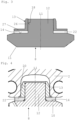
- Figure 3 shows schematically that an intermediate element 22, e.g. a friction disk and/or a spring disk, can be arranged between the sliding blocks, which are T-shaped in longitudinal section (in the exemplary embodiment shown, between the first sliding block 13), and the back surfaces 14 of the three identical differential gears 8.
- the sliding block 13 has a first leg 26 and a second leg 27 which runs perpendicular to the first leg 26.
- the first leg 26 runs coaxially around a longitudinal axis L1 of the pin 12 of the differential gear 8.
- the first leg 26 of the sliding block 13 has the receptacle 18 matching the pin 12, wherein the pin 12 is rotatably mounted within the receptacle 18, in the exemplary embodiment shown by means of a sliding bearing.
- the first leg 26 is slidably mounted in the first slide track 20 of the housing 2 of the differential gear 1.
- the back surface 14 of the compensating gear 8 is supported on the second leg 27 of the T-shaped sliding block 13, in particular via the intermediate element 22.
- the friction disc can reduce wear on the sliding block 13 and on the housing 2, which can be made of a softer metal than the sliding block 13, which can be made of a hardened metal, for example.
- the intermediate element 22 can also be a differential gear spring washer, which exerts a differential gear spring force on the differential gear 8, so that the differential gear spring force presses the differential gear toothing 11 of the differential gear 8 into engagement with the two side gear toothings 5, 7 of the two side gears 4, 6.
- a friction disc can also be combined with a differential gear spring washer, for example by placing the two on top of each other, or by arranging a differential gear spring washer between two friction discs. Friction discs and/or Differential gear spring washers may be arranged as described above in connection with the first sliding block 13 and the first differential gear 8.
- Figure 4 shows that the sliding blocks, in the example shown the first sliding block13, can alternatively be tubular (only a first leg and no second leg according to Figure 3 ).
- An intermediate element 22 can be arranged between the back surface 14 of the differential gear 8 on the one hand and the sliding block 13 and the housing 2 on the other hand, similar to what is described in connection with Figure 3 has been described.
- Figure 5 shows the differential gear 1 to Figure 1 , wherein a thrust washer 24 is arranged between the cover 3 and the first side gear 4.
- a side gear spring washer 25 is arranged between the second side gear 6 and the housing 2.
- the side gear spring washer 25 exerts a side gear spring force on the second side gear 6, so that the side gear spring force presses the second side gear toothing 7 of the second side gear 6 into engagement with the differential gear toothings 11, 16 of the differential gears 8, 9.
- the thrust washer 24 is optional and can be omitted, which can be achieved by Figure 6 Alternatively, the thrust washer 24 can be provided, with the axle shaft gear spring washer 25 being omitted, which is achieved by Figure 7 is shown.
- Figures 8 to 13 show an alternative sliding block 113 and/or an alternative differential gear 108 for the differential gear 1 according to Figure 1 .
- the sliding block 113 has a pin 112 and the compensating gear 108 comprises a receptacle 118 that fits the pin 112.
- the pin 112 of the sliding block 113 can be inserted into the receptacle 118, so that the compensating gear 108 is rotatably mounted on the sliding block 113, as shown in Figures 10 and 11 is shown.
- the pin 112 is in the Figures 8 to 13 shown embodiment is connected in one piece with the rest of the sliding block 113.
- the sliding block 113 can have a bore 119 which is Figure 11 indicated by dotted lines.
- the pin 112 is a separate component from the sliding block 113 and can be referred to as a cylindrical pin.
- the cylindrical pin 112 is inserted into the bore 119 of the sliding block 113, in particular in a rotationally fixed manner. inserted or mounted.
- the cylindrical pin 112 protrudes from the bore 119 of the sliding block 113, whereby the compensating gear 108 is rotatably mounted on the cylindrical pin 112 with its receptacle 118 matching the cylindrical pin 112.
- FIG 14 shows an alternative spider or pinion type differential 201.
- the differential 201 comprises a housing 202, two axle gears 203 (one of which is Figure 14 shown) each with a side gear toothing 204. Both side gears 203 are bevel gears. Thus, the side gear toothings 204 are also bevel gear toothings.
- the differential gear 201 comprises a total of three identical differential gears 205, which are arranged equidistantly in a circumferential direction, spaced 120° apart from one another. In the exemplary embodiment shown, all three differential gears 205 are bevel gears.
- the differential gears 205 each have a differential gear toothing 206 on their radially outer surface, which is a bevel gear toothing.
- the differential gear 201 further comprises a pin arrangement 207 with three pins 208. Starting from a common center point 209 of the pin arrangement 207, the three pins 208 are arranged equidistantly in a circumferential direction, each spaced 120° apart from one another. The three pins 208 are rigidly connected to one another, in the illustrated embodiment as a single piece.
- the three differential gears 205 are each rotatably mounted on a central portion 210 of one of the three pins 208, in the illustrated embodiment by means of a plain bearing.
- Each of the pins 208 further has a freely extending (distal) end 211, which is displaceably mounted in one of three slideways 212 formed by the housing 202.
- the slideways 212 extend between the two axle shaft gears 203 in such a way that the journal arrangement 207 with all three journals 208 and the differential gears 205 rotatably mounted thereon can move back and forth between the two axle shaft gears 203. Due to this displaceability, the axle shaft gears - caused by displacement forces of the meshing between the axle shaft gears and differential gears - can be moved into a central position, as is the case with the differential gear 1 according to Figures 1 and 2 has been described.
- Figure 15 shows another differential gear 301 from the outside, which in its interior, for example, like the differential gear according to Figure 1 or how the differential gear 201 after Figure 14
- the differential gear has a housing 302 and a cover 303, which closes the housing 302 on one of its end faces.
- the housing 302 has a tripod geometry.
- a tripod geometry can be understood in connection with Figure 15
- the housing 302 has three material and weight-saving pockets 304 (indentations) on its outer side, which are directed inwards.
- the three pockets 304 are arranged at a distance of 120° from one another in the circumferential direction.
- An element for driving the differential gear 301 e.g.
- a drive gear or part of an axle shaft can have inward-facing bulges designed to be complementary to the three pockets 304, which are also arranged at a distance of 120° from one another in the circumferential direction.
- the bulges of the element for driving the differential gear 301 can be brought into engagement with the three pockets 304 of the housing 302, so that a positive connection is created and so that torque can be transmitted.
Landscapes
- Engineering & Computer Science (AREA)
- General Engineering & Computer Science (AREA)
- Mechanical Engineering (AREA)
- Retarders (AREA)
Applications Claiming Priority (2)
| Application Number | Priority Date | Filing Date | Title |
|---|---|---|---|
| DE102021004450 | 2021-08-31 | ||
| EP22000194.5A EP4141289A1 (fr) | 2021-08-31 | 2022-08-10 | Différentiel pour un véhicule |
Related Parent Applications (1)
| Application Number | Title | Priority Date | Filing Date |
|---|---|---|---|
| EP22000194.5A Division EP4141289A1 (fr) | 2021-08-31 | 2022-08-10 | Différentiel pour un véhicule |
Publications (2)
| Publication Number | Publication Date |
|---|---|
| EP4542084A2 true EP4542084A2 (fr) | 2025-04-23 |
| EP4542084A3 EP4542084A3 (fr) | 2025-05-14 |
Family
ID=82898882
Family Applications (2)
| Application Number | Title | Priority Date | Filing Date |
|---|---|---|---|
| EP22000194.5A Pending EP4141289A1 (fr) | 2021-08-31 | 2022-08-10 | Différentiel pour un véhicule |
| EP25152901.2A Pending EP4542084A3 (fr) | 2021-08-31 | 2022-08-10 | Différentiel pour un véhicule |
Family Applications Before (1)
| Application Number | Title | Priority Date | Filing Date |
|---|---|---|---|
| EP22000194.5A Pending EP4141289A1 (fr) | 2021-08-31 | 2022-08-10 | Différentiel pour un véhicule |
Country Status (2)
| Country | Link |
|---|---|
| EP (2) | EP4141289A1 (fr) |
| DE (1) | DE102022002887B4 (fr) |
Citations (2)
| Publication number | Priority date | Publication date | Assignee | Title |
|---|---|---|---|---|
| US4959043A (en) | 1989-08-29 | 1990-09-25 | Chrysler Corporation | Multi-pinion differential assembly |
| DE102018211812A1 (de) | 2018-07-16 | 2020-01-16 | Audi Ag | Differentialgetriebe für ein Kraftfahrzeug |
Family Cites Families (9)
| Publication number | Priority date | Publication date | Assignee | Title |
|---|---|---|---|---|
| US2985035A (en) * | 1958-07-18 | 1961-05-23 | Toth John Michael | Differential mechanisms |
| JPS58165359U (ja) * | 1982-04-30 | 1983-11-04 | いすゞ自動車株式会社 | 差動装置 |
| JPH0680943U (ja) * | 1993-04-28 | 1994-11-15 | ダイハツ工業株式会社 | ディファレンシャル装置 |
| JPH0814362A (ja) * | 1994-06-30 | 1996-01-16 | Suzuki Motor Corp | 差動制限装置 |
| US5980416A (en) * | 1997-08-06 | 1999-11-09 | Sven B. Gafvert | Differential for a vehicle |
| US7278948B2 (en) * | 2005-04-25 | 2007-10-09 | American Axle & Manufacturing, Inc. | “Zero” lash spherical differential assembly using spring washers |
| US8043188B2 (en) * | 2008-09-04 | 2011-10-25 | Dana Heavy Vehicle Systems Group, Llc | Spider-less vehicle differential |
| JP2018096502A (ja) * | 2016-12-15 | 2018-06-21 | 武蔵精密工業株式会社 | 差動装置 |
| US12140223B2 (en) * | 2019-10-18 | 2024-11-12 | Lego A/S | Toy differential |
-
2022
- 2022-08-10 EP EP22000194.5A patent/EP4141289A1/fr active Pending
- 2022-08-10 DE DE102022002887.5A patent/DE102022002887B4/de active Active
- 2022-08-10 EP EP25152901.2A patent/EP4542084A3/fr active Pending
Patent Citations (2)
| Publication number | Priority date | Publication date | Assignee | Title |
|---|---|---|---|---|
| US4959043A (en) | 1989-08-29 | 1990-09-25 | Chrysler Corporation | Multi-pinion differential assembly |
| DE102018211812A1 (de) | 2018-07-16 | 2020-01-16 | Audi Ag | Differentialgetriebe für ein Kraftfahrzeug |
Also Published As
| Publication number | Publication date |
|---|---|
| EP4542084A3 (fr) | 2025-05-14 |
| DE102022002887A1 (de) | 2023-03-02 |
| EP4141289A1 (fr) | 2023-03-01 |
| DE102022002887B4 (de) | 2025-10-16 |
Similar Documents
| Publication | Publication Date | Title |
|---|---|---|
| DE3206992C2 (fr) | ||
| EP3287298B1 (fr) | Moyeu et série de moyeux | |
| DE102007010559A1 (de) | Differentialanordnung für eine Arbeitsmaschine | |
| WO2013174553A1 (fr) | Palier lisse combiné dans un train épicycloïdal | |
| DE60211261T2 (de) | Rad mit Endvorrichtung | |
| DE202019103770U1 (de) | Doppelgetriebe mit vorteilhafter Auskragung | |
| DE19800328A1 (de) | Kraftübertragungssystem für ein Fahrzeug | |
| DE102019208451A1 (de) | Lenkgetriebe für ein Kraftfahrzeug | |
| DE102022003206A1 (de) | Elektrisches Antriebssystem für ein Kraftfahrzeug sowie Kraftfahrzeuge | |
| EP2473761B1 (fr) | Différentiel | |
| EP0965511B1 (fr) | Ensemble-essieu pour véhicules ferroviaires | |
| DE60116571T2 (de) | Zwillingsräder mit Differential | |
| DE60312910T2 (de) | Unabhängig drehende Räder | |
| DE102021213941B3 (de) | Aktuator einer Steer-by-wire-Lenkung sowie Steer-by-wire-Lenkung | |
| DE102022002887B4 (de) | Differentialgetriebe für ein Fahrzeug | |
| DE102011087568A1 (de) | Bolzenlagerung mit Absatz | |
| EP1502799B1 (fr) | Entraînement de moyeu de roue | |
| DE850696C (de) | Ausgleichgetriebe, insbesondere fuer Kraftfahrzeuge | |
| DE102017219546B4 (de) | Zahnradanordnung | |
| DE10229862B4 (de) | Universaldifferentialantrieb | |
| EP1199237B1 (fr) | Transmission pour véhicule ferroviaire | |
| DE19858033A1 (de) | Differentialgetriebe für Kraftfahrzeuge | |
| DE3731668C2 (fr) | ||
| WO1991019619A1 (fr) | Entrainement d'essieu pour un vehicule automobile | |
| DE102007060684A1 (de) | Als Starrachse ausgebildete Antriebsachse |
Legal Events
| Date | Code | Title | Description |
|---|---|---|---|
| PUAI | Public reference made under article 153(3) epc to a published international application that has entered the european phase |
Free format text: ORIGINAL CODE: 0009012 |
|
| STAA | Information on the status of an ep patent application or granted ep patent |
Free format text: STATUS: THE APPLICATION HAS BEEN PUBLISHED |
|
| REG | Reference to a national code |
Ref country code: DE Ref legal event code: R079 Free format text: PREVIOUS MAIN CLASS: F16H0048380000 Ipc: F16H0048220000 |
|
| PUAL | Search report despatched |
Free format text: ORIGINAL CODE: 0009013 |
|
| AC | Divisional application: reference to earlier application |
Ref document number: 4141289 Country of ref document: EP Kind code of ref document: P |
|
| AK | Designated contracting states |
Kind code of ref document: A2 Designated state(s): AL AT BE BG CH CY CZ DE DK EE ES FI FR GB GR HR HU IE IS IT LI LT LU LV MC MK MT NL NO PL PT RO RS SE SI SK SM TR |
|
| AK | Designated contracting states |
Kind code of ref document: A3 Designated state(s): AL AT BE BG CH CY CZ DE DK EE ES FI FR GB GR HR HU IE IS IT LI LT LU LV MC MK MT NL NO PL PT RO RS SE SI SK SM TR |
|
| RIC1 | Information provided on ipc code assigned before grant |
Ipc: F16H 48/38 20120101ALI20250404BHEP Ipc: F16H 48/22 20060101AFI20250404BHEP |
|
| STAA | Information on the status of an ep patent application or granted ep patent |
Free format text: STATUS: REQUEST FOR EXAMINATION WAS MADE |
|
| 17P | Request for examination filed |
Effective date: 20251022 |