EP4539293A1 - Anpassungssystem, energiespeichersystem dafür und anpassungsverfahren dafür - Google Patents
Anpassungssystem, energiespeichersystem dafür und anpassungsverfahren dafür Download PDFInfo
- Publication number
- EP4539293A1 EP4539293A1 EP23818784.3A EP23818784A EP4539293A1 EP 4539293 A1 EP4539293 A1 EP 4539293A1 EP 23818784 A EP23818784 A EP 23818784A EP 4539293 A1 EP4539293 A1 EP 4539293A1
- Authority
- EP
- European Patent Office
- Prior art keywords
- battery
- target
- cluster
- power converter
- clusters
- Prior art date
- Legal status (The legal status is an assumption and is not a legal conclusion. Google has not performed a legal analysis and makes no representation as to the accuracy of the status listed.)
- Pending
Links
Images


Classifications
-
- H02J7/933—
-
- H—ELECTRICITY
- H01—ELECTRIC ELEMENTS
- H01M—PROCESSES OR MEANS, e.g. BATTERIES, FOR THE DIRECT CONVERSION OF CHEMICAL ENERGY INTO ELECTRICAL ENERGY
- H01M10/00—Secondary cells; Manufacture thereof
- H01M10/42—Methods or arrangements for servicing or maintenance of secondary cells or secondary half-cells
- H01M10/425—Structural combination with electronic components, e.g. electronic circuits integrated to the outside of the casing
-
- H—ELECTRICITY
- H01—ELECTRIC ELEMENTS
- H01M—PROCESSES OR MEANS, e.g. BATTERIES, FOR THE DIRECT CONVERSION OF CHEMICAL ENERGY INTO ELECTRICAL ENERGY
- H01M10/00—Secondary cells; Manufacture thereof
- H01M10/42—Methods or arrangements for servicing or maintenance of secondary cells or secondary half-cells
- H01M10/44—Methods for charging or discharging
- H01M10/441—Methods for charging or discharging for several batteries or cells simultaneously or sequentially
-
- H—ELECTRICITY
- H01—ELECTRIC ELEMENTS
- H01M—PROCESSES OR MEANS, e.g. BATTERIES, FOR THE DIRECT CONVERSION OF CHEMICAL ENERGY INTO ELECTRICAL ENERGY
- H01M50/00—Constructional details or processes of manufacture of the non-active parts of electrochemical cells other than fuel cells, e.g. hybrid cells
- H01M50/50—Current conducting connections for cells or batteries
- H01M50/502—Interconnectors for connecting terminals of adjacent batteries; Interconnectors for connecting cells outside a battery casing
- H01M50/509—Interconnectors for connecting terminals of adjacent batteries; Interconnectors for connecting cells outside a battery casing characterised by the type of connection, e.g. mixed connections
- H01M50/512—Connection only in parallel
-
- H02J7/40—
-
- H02J7/50—
-
- H02J7/56—
-
- H02J7/82—
-
- H02J2105/37—
-
- H—ELECTRICITY
- H02—GENERATION; CONVERSION OR DISTRIBUTION OF ELECTRIC POWER
- H02J—CIRCUIT ARRANGEMENTS OR SYSTEMS FOR SUPPLYING OR DISTRIBUTING ELECTRIC POWER; SYSTEMS FOR STORING ELECTRIC ENERGY
- H02J2207/00—Indexing scheme relating to details of circuit arrangements for charging or depolarising batteries or for supplying loads from batteries
- H02J2207/20—Charging or discharging characterised by the power electronics converter
-
- Y—GENERAL TAGGING OF NEW TECHNOLOGICAL DEVELOPMENTS; GENERAL TAGGING OF CROSS-SECTIONAL TECHNOLOGIES SPANNING OVER SEVERAL SECTIONS OF THE IPC; TECHNICAL SUBJECTS COVERED BY FORMER USPC CROSS-REFERENCE ART COLLECTIONS [XRACs] AND DIGESTS
- Y02—TECHNOLOGIES OR APPLICATIONS FOR MITIGATION OR ADAPTATION AGAINST CLIMATE CHANGE
- Y02E—REDUCTION OF GREENHOUSE GAS [GHG] EMISSIONS, RELATED TO ENERGY GENERATION, TRANSMISSION OR DISTRIBUTION
- Y02E60/00—Enabling technologies; Technologies with a potential or indirect contribution to GHG emissions mitigation
- Y02E60/10—Energy storage using batteries
Definitions
- the present disclosure relates to the technical field of new energy vehicles, and specifically to a regulating system and an energy storage system and a regulating method thereof.
- the present disclosure provides a regulating system, configured to regulate a battery system, wherein the battery system includes a plurality of battery clusters, the regulating system includes a first power converter and a control unit, wherein a first end of the first power converter is configured to be connected in series with each of the battery clusters, a second end of the first power converter is configured to be connected to a power source, and the control unit is connected to the first power converter and each of the battery clusters in communication respectively; and the control unit is configured to disconnect a parallel connection between a target battery cluster and other battery clusters, and control connection between the target battery cluster and the first power converter to conduct.
- the regulating system further includes a plurality of first controllable switches and a plurality of second controllable switches, wherein number of the first controllable switches and number of the second controllable switches are the same as number of the battery clusters, wherein each of the battery clusters is connected in series with one of the first controllable switches and then connected in parallel with other battery clusters, and each of the battery clusters is connected in series with the first power converter through the second controllable switch, wherein the control unit is configured to control the first controllable switch connected to the target battery cluster to disconnect, so as to disconnect parallel connection between the target battery cluster and other battery clusters; and to control the second controllable switch between the target battery cluster and the first power converter, so as to control the connection between the target battery cluster and the first power converter to conduct.
- the target battery cluster can be switched between being connected in parallel with other battery clusters and being connected in series with the first power converter, such that when regulating the target battery cluster, the regulation of switching control can be realized through simple switch control.
- the circuit design is simplified and the design and device costs are saved.
- the second end of the first power converter is connected in parallel with any of the plurality of battery clusters, so that the battery cluster connected in parallel with the second end of the first power converter is used as the power source.
- the parallel battery clusters are uses as a power source, thereby saving the device cost of the power source.
- the battery system further includes a power source, wherein the second end of the first power converter is connected to the power source.
- the present disclosure provides an energy storage system, including a battery system and the regulating system of any one of implementation modes in the first aspect, wherein the battery system includes a plurality of battery clusters and a second power converter, wherein the plurality of battery clusters are connected in parallel and then connected to the second power converter, the first end of the first power converter is connected in series with each of the battery clusters, the second end of the first power converter is configured to be connected to the power source, and the control unit is connected to the first power converter and each of the battery clusters in communication respectively.
- the battery system includes a plurality of battery clusters and a second power converter, wherein the plurality of battery clusters are connected in parallel and then connected to the second power converter, the first end of the first power converter is connected in series with each of the battery clusters, the second end of the first power converter is configured to be connected to the power source, and the control unit is connected to the first power converter and each of the battery clusters in communication respectively.
- the first power converter is designed to be connected in series with each battery cluster in the battery system, and the control unit is designed to communicate with the first power converter and each battery cluster, then the parallel connection between the target battery cluster and other battery clusters is disconnected, and the connection between the target battery cluster and the first power converter is controlled to conduct, so that the target battery cluster is regulated according to the target current command through the first power converter, so as to make the state of charge of the target battery cluster close to the target state of charge, that is, close to the state of charge of other battery clusters, thereby eliminating the difference in state of charge between the target battery cluster and other battery clusters, so as to improve the constant power operation capability of the energy storage system; and in this solution, multiple battery clusters share a first power converter, which has low device cost, low cost for heat dissipation, no need to change the existing battery system, and low modification cost.
- the present disclosure provides a regulating method, including: disconnecting parallel connection between a target battery cluster and other battery clusters, and controlling connection between the target battery cluster and a first power converter to conduct; sending a target current command to the first power converter, so as to regulate the target battery cluster according to the target current command through the first power converter.
- the parallel connection between the target battery cluster and other battery clusters is disconnected in this solution, the connection between the target battery cluster and the first power converter is controlled to conduct, and the target current command is sent to the first power converter, so as to regulate the target battery cluster according to the target current command through the first power converter, making the state of charge of the target battery cluster close to the target state of charge, that is, close to the state of charge of other battery clusters, thereby eliminating the difference in SOC between the target battery cluster and other battery clusters, so as to improve the constant power operation capability of the energy storage system.
- the method before disconnecting the parallel connection between the target battery cluster and other battery clusters, the method further includes: collecting state of charge of each of the battery clusters; and comparing the state of charge of each of the battery clusters with a target state of charge, and determining the battery cluster whose state of charge has a preset relationship with the target state of charge as the target battery cluster.
- determining the battery cluster whose state of charge has the preset relationship with the target state of charge as the target battery cluster includes determining the battery cluster with the highest absolute value of difference between the state of charge and the target state of charge as the target battery cluster.
- the battery cluster with the largest absolute value of the difference between the state of charge and the target state of charge is taken as the target battery cluster, thereby regulating the battery cluster with the largest SOC difference among the multiple battery clusters, so that the SOC difference in the battery system can be effectively eliminated, and the output power of the battery system can be effectively improved.
- the method before sending the target current command to the first power converter, the method further includes: calculating difference between the state of charge of the target battery cluster and the target state of charge, to obtain difference of state of charge; obtaining a present current value of the target battery cluster; calculating a target regulated current value according to the difference of state of charge and the present current value; and generating the target current command according to the target regulated current value.
- the target regulated current value is accurately calculated by the difference of state of charge and the present current value of the target battery cluster, and then a target current command is generated based on the target regulated current value, so that the regulation of the first power converter on the target battery cluster can be accurately controlled, making the SOC regulation of the target battery cluster more accurate.
- calculating the present current value of the target battery cluster includes: obtaining a bus voltage, a voltage of the first power converter, a battery voltage of the target battery cluster, and an impedance of the target battery cluster; calculating differences between the bus voltage and the voltage of the first power converter, as well as the battery voltage of the target battery cluster, so as to obtain a present current voltage difference; calculating a quotient of the present current voltage difference and the impedance of the target battery cluster, so as to obtain the present current value of the target battery cluster.
- the method before sending the target current command to the first power converter, the method further includes: calculating difference between the state of charge of the target battery cluster and the target state of charge, to obtain difference of state of charge; obtaining a present current value of the target battery cluster; acquiring a current working status of the battery system; determining a target regulated current value according to the current working status, the difference of charge state, and the present current value of the target battery cluster; generating the target current command according to the target regulated current value.
- determining the target regulated current value according to the current working status, the difference of charge state, and the present current value of the target battery cluster includes: determining a target regulating coefficient according to the current working status and the difference of state of charge; calculating a product of the target regulating coefficient and the present current value of the target battery cluster, to obtain the target regulated current value.
- determining the target regulating coefficient according to the current working status and the difference of state of charge includes: determining, when the current working status of the battery system is charging and the difference of state of charge is greater than 0, the target regulating coefficient as a first preset coefficient; determining, when the current working status of the battery system is charging and the difference of state of charge is smaller than 0, the target regulating coefficient as a second preset coefficient; determining, when the current working status of the battery system is discharging and the difference of state of charge is greater than 0, the target regulating coefficient as a third preset coefficient; determining, when the current working status of the battery system is discharging and the difference of state of charge is smaller than 0, the target regulating coefficient as a fourth preset coefficient, wherein the first and fourth preset coefficients are less than 1, and the second and third preset coefficients are greater than 1.
- the target battery cluster when the battery system is in a discharge state, if the SOC of the target battery cluster is higher than other battery clusters, the target battery cluster will be discharged faster; if the SOC of the target battery cluster is lower than other battery clusters, the target battery cluster will be charged Slower, thereby balancing the SOC areas of multiple battery clusters, allowing the battery system to discharge all power or fully charge as much as possible, thus improving the constant power operation capability of the energy storage system.
- the method before disconnecting the parallel connection between the target battery cluster and other battery clusters, the method further includes: acquiring a battery voltage of each of the battery clusters before connecting the plurality of battery clusters in parallel; determining the battery cluster whose battery voltage meets a preset parallel condition as a parallel-connectable battery cluster; controlling a plurality of parallel-connectable battery clusters to be connected in parallel.
- the battery clusters that meet the preset parallel conditions are determined as parallel battery clusters, so that all the parallel-connectable battery clusters are connected in parallel to avoid the circulating current caused by the parallel connection of battery clusters with significant SOC differences when powered on, thereby improving the reliability of the battery system.
- determining, from the battery clusters, the candidate parallel-connectable battery cluster with the difference between the battery voltage and the target battery voltage greater than the first preset voltage threshold and less than the second preset voltage threshold includes: determining, if there are one battery cluster with the difference between the battery voltage and the target battery voltage greater than the first preset voltage threshold and less than the second preset voltage threshold, the battery cluster with the difference between the battery voltage and the target battery voltage greater than the first preset voltage threshold and less than the second preset voltage threshold as the candidate parallel-connectable battery cluster; and determining, if there are a plurality of battery clusters with the difference between the battery voltage and the target battery voltage greater than the first preset voltage threshold and less than the second preset voltage threshold, the battery cluster with the smallest difference between the battery voltage and the target battery voltage as the candidate parallel-connectable battery cluster among the plurality of battery clusters with the difference between the battery voltage and the target battery voltage greater than the first preset voltage threshold and less than the second preset voltage threshold.
- the control module controls the parallel connection between the target battery cluster and other battery clusters, and the connection between the target battery cluster and the first power converter is controlled to conduct.
- the target current command is sent to the first power converter by the sending module, so that the target battery cluster is regulated by the first power converter according to the target current command, making the state of charge of the target battery cluster close to the target charge state, that is, close to the state of charge of other battery clusters, thereby eliminating the difference of the state of charge between the target battery cluster and other battery clusters, so as to improve the constant power operation ability of the energy storage system.
- the present disclosure provides electronic equipment, including a memory and a processor, wherein the memory stores a computer program, wherein the processor, when executing the computer program, implements the method in any one of optional implementations in the third and fourth aspects.
- the reference numbers in the specific implementation modes are as follows: 1-regulating system; 10-first power converter; 20-control unit; 2-battery system; 21-battery cluster; 22-second power converter; K-first controllable switch; B-second controllable switch; C-power source; 3-energy storage system; 1200-control module; 1210-sending module; 1220-collection module; 1230-determination module; 1240-calculation module; 1250-generation module; 1260-acquisition module ; 13-electronic equipment; 1301-processor; 1302-memory; 1303-communication bus.
- an embodiment means that a particular feature, structure, or characteristic described in connection with the embodiment can be included in at least one embodiment of the present application.
- the appearances of this phrase in various places in the Description are not necessarily all referring to the same embodiment, nor are separate or alternative embodiments mutually exclusive of other embodiments. Those skilled in the art understand, both explicitly and implicitly, that the embodiments described herein may be combined with other embodiments.
- multiple refers to more than two (including two), and similarly, “multiple groups” refers to more than two groups (including two groups), and “multiple pieces” refers to two or more pieces (including two pieces).
- connection can be a fixed connection, a detachable connection, or integration; it can be a mechanical connection or an electrical connection; it can be a direct connection or an indirect connection through an intermediary; it can be an internal communication of two elements or an interaction of two elements.
- connection can be a fixed connection, a detachable connection, or integration; it can be a mechanical connection or an electrical connection; it can be a direct connection or an indirect connection through an intermediary; it can be an internal communication of two elements or an interaction of two elements.
- Batteries are not only used in energy storage power systems such as hydraulic, thermal, wind and solar power stations, but are also widely used in electric vehicles such as electric bicycles, electric motorcycles and electric cars, as well as in many fields such as military equipment and aerospace. As battery application fields continue to expand, its market demand is also expanding.
- the inventor noticed that the current solution is to arrange a first power converter in each battery cluster branch, and the SOC between different battery clusters are balanced by the first power converter, so that the SOC of each battery cluster is equal, that is, the available power of different battery clusters is always consistent, solving the problem of parallel mismatch between different battery clusters.
- a first power converter is connected in series in each branch, the device cost for the design of the energy storage system is increased.
- heat dissipation of the original energy storage system cannot meet the demand, it may also lead to improvements in heat dissipation design and an increase in heat dissipation costs.
- the inventor has designed a regulating system and an energy storage system and a regulating method thereof after in-depth research.
- the regulating system can sequentially regulate different battery clusters by sharing a first power converter among multiple battery clusters under the control of the regulating method, thereby saving costs while solving the problem of SOC differences in different battery clusters.
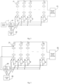
- the regulating system 1 can regulate the battery system 2.
- the battery system 2 includes a plurality of battery clusters 21.
- the plurality of battery clusters 21 may specifically include battery clusters A1 to battery clusters An, as shown in Fig. 1 .
- the plurality of battery clusters 21 are connected in parallel and then configured to be connected to the second power converter 22, so to achieve power output.
- each of the battery clusters 21 may include a plurality of batteries 211 connected in series.
- the second power converter 21 may be a DC/AC converter or an inverter, and it has an effect of converting the DC power supply of the plurality of battery clusters 21 connected in parallel into AC power with stable output voltage and frequency.
- the regulating system 1 includes a first power converter 10 and a control unit 20.
- the control unit 20 can be communicatively connected to the first power converter 10.
- the connection mode between the regulating system 1 and the battery system 2 can be shown in Fig.1 .
- a first end of the first power converter 10 is connected in series with each of the battery clusters 21.
- a second end of the power converter 10 is configured to be connected to a power source C, and the control unit 20 can communicate with each of the battery clusters 21.
- all of the battery clusters 21 in the battery system 2 are connected in parallel and conductive so as to transmit electric energy to the second power converter to achieve electric energy output.
- the control unit 20 can detect state of charge of each of the battery clusters 21. When the difference in state of charge is large, the regulating system 1 will perform regulation.
- the specific regulating process is: the control unit 20 first determines a target battery cluster that needs to be regulated among the plurality of battery clusters 21, then disconnects parallel connection between the target battery cluster and other battery clusters, and controls the connection between the target battery cluster and the first power converter 10 to conduct, so that the first power converter 10 regulates the target battery cluster according to the target current command, thereby eliminating difference in SOC between the target battery cluster and other battery clusters, and improving the power output of the battery system.
- battery cluster A1 to battery cluster An are all connected in parallel to the second power converter 22, and the control unit 20 determines that battery cluster A1 is the target battery cluster, then the control unit disconnects the parallel connections between battery cluster A1 and other battery clusters.
- the connection between the battery cluster A1 and the first power converter 10 is conductive, thus the first power converter 10 regulates the target battery cluster according to the target current commend, so that the state of charge of the battery cluster A1 is close to the target state of other battery clusters.
- the target battery cluster may be a battery cluster whose state of charge has a preset relationship with the target state of charge. Specifically, it may be the battery cluster with the largest absolute value of the difference between the state of charge and the target state of charge, or it may be any battery cluster among multiple battery clusters with the difference between the state of charge and the target state of charge being greater than a preset value.
- the target state of charge may be the average state of charge of multiple battery clusters, or the maximum or minimum state of charge among multiple battery clusters.
- control unit 20 can disconnect the target battery cluster from the first power converter 10, then connect the target battery cluster in parallel with other parallel battery clusters to connect to the battery system.
- the regulating system also includes a plurality of first controllable switches K and a plurality of second controllable switches B, wherein the number of the plurality of first controllable switches K is equal to the number of the plurality of second controllable switches B.
- Each battery cluster 21 is connected in parallel with other battery clusters through a first controllable switch K, and each battery cluster 21 is connected to a second controllable switch B and then to the first power converter 10.
- the battery cluster A1 is connected to other battery clusters in parallel through the first controllable switch K, and the battery cluster A1 is connected the second controllable switch B and then to the first power converter 10.
- the control unit 20 can control the first controllable switch K connected to the target battery cluster to open, so that the parallel connection between the target battery cluster and other battery clusters is disconnected, and then it controls the second controllable switch B connected to the target battery cluster to close, so that the connection between the target battery cluster and the first power converter 10 is conductive, thereby regulating the target battery cluster through the first power converter 10.
- the control unit 20 can control the second controllable switch B connected to the target battery cluster to close, thereby disconnecting the target battery cluster from the first power converter 10, and then control the first controllable switch B connected to the target battery cluster to close, so that the target battery cluster is connected in parallel with other battery clusters.
- the first controllable switch K and the second controllable switch B can use the same controllable switch, or different controllable switches.
- both the first controllable switch K and the second controllable switch B can be controlled by a controllable switch such as a thyristor or a silicon controlled rectifier.
- the target battery cluster can be switched between being connected in parallel with other battery clusters and being connected in series with the first power converter, such that when regulating the target battery cluster, the regulation of switching control can be realized through simple switch control.
- the circuit design is simplified and the design and device costs are saved.
- the second end of the first power converter 10 may be connected in parallel with any one of the plurality of battery clusters, so that the battery cluster connected in parallel with the second end of the first power converter 10 serves as the power source C.
- the second end of the first power converter 10 is connected in parallel with the battery cluster A1, and then the battery cluster A1 serves as the power source C.
- the regulating system 1 may also include the power source C, and the second end of the first power converter 10 is connected to the power source C, wherein the power source C includes but is not limited to independent batteries, supercapacitors, DC bus, etc.
- the first power converter 10 may be a non-isolated DC/DC converter or an isolated DC/DC converter; when the first power converter 10 is connected in series with the battery cluster, it can be connected in series with either end of the battery cluster (positive electrode or negative electrode), or it can be connected in series with a certain position in the battery cluster.
- the present disclosure provides an energy storage system.
- the energy storage system 3 includes the regulating system 1 described in any of the aforementioned embodiments and the aforementioned battery system 2.
- the connection method between the regulating system 1 and the battery system 2 has been described previously and will not be repeated here.
- the present application provides a regulating method, which can be applied to the aforementioned regulating system.
- the regulating method can be executed by the control unit in the aforementioned regulating system.
- the regulating method can be implemented in the following manner.
- Step S600 disconnect the parallel connection between the target battery cluster and other battery clusters, and controlling the connection between the target battery cluster and the first power converter to conduct.
- Step S610 Send a target current command to the first power converter to regulate the target battery cluster according to the target current command through the first power converter.
- the control unit can communicate with each battery cluster to obtain the state of charge (SOC) of each battery cluster in the current state, and then the SOC of each battery cluster is compared with the target state of charge (target SOC), so that the battery cluster whose SOC has a preset relationship with the target SOC is determined as the target battery cluster.
- SOC state of charge
- target SOC target state of charge
- the parallel connection between the target battery cluster and other battery clusters is disconnected, the connection between the target battery cluster and the first power converter is controlled to conduct, and the target current command is sent to the first power converter, so that the first power converter regulates the target battery cluster according to the target current command, making the SOC of the target battery cluster close to the target SOC, thereby basically eliminating the difference in SOC between the target battery cluster and other battery clusters, so as to improve the constant power operation capability of the energy storage system.
- the target battery command can be generated by a target regulated current
- the target regulated current can regulate the SOC of the target battery cluster.
- the first power converter can regulate its own output according to the target current command, so as to regulate the line current connecting the first power converter to the target battery cluster, thereby regulating the SOC of the target battery cluster.
- the parallel connection between the target battery cluster and other battery clusters is disconnected, the connection between the target battery cluster and the first power converter is controlled to conduct, and the target current command is sent to the first power converter, so as to regulate the target battery cluster according to the target current command through the first power converter, making the state of charge of the target battery cluster close to the target state of charge, that is, close to the state of charge of other battery clusters, thereby eliminating the difference in SOC between the target battery cluster and other battery clusters, so as to improve the constant power operation capability of the energy storage system.
- this solution can determine the target battery cluster among multiple battery clusters in the following method.
- the state of charge of each battery cluster can be collected, the state of charge of each battery cluster is compared with the target state of charge, and the battery cluster with the largest absolute value of the difference between the state of charge and the target state of charge is finally determined to be the target battery cluster.
- the battery cluster with the largest absolute value of the difference between the state of charge and the target state of charge is taken as the target battery cluster in this solution,, thereby regulating the battery cluster with the largest SOC difference among the multiple battery clusters, so that the SOC difference in the battery system can be effectively eliminated, and the output power of the battery system can be effectively improved.
- the state of charge of each battery cluster can be collected, the state of charge of each battery cluster is compared with the target state of charge, and the battery clusters with difference between the state of charge and the target state of charge greater than a preset value are gathered together, then a battery cluster is randomly selected from the set as the target battery cluster.
- the aforementioned target state of charge may be the average state of charge of all battery clusters, or may be the SOC value of the battery cluster with the smallest SOC or the largest SOC among all battery clusters.
- control unit can send a target current command to the first power converter.
- target current command can be determined and generated in the following method.
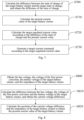
- Step S720 Calculate the target regulated current value according to the difference of the state of charge and the present current value.
- Step S730 Generate a target current command according to the target regulated current value.
- control unit may calculate the difference between the SOC of the target battery cluster and the target SOC to obtain ⁇ SOC.
- the target SOC can be the average SOC of all battery clusters, or the maximum or minimum SOC value of all battery clusters.
- control unit may calculate the present current value of the target battery cluster, wherein the present current value represents a line current value after the target battery cluster is connected in series with the first power converter.
- control unit of this solution can perform the calculation operations of step S700 and step S710 at the same time, or can perform them in sequence, which is not limited by this solution.
- the present current value of the target battery cluster can be calculated in the following method, as shown in Fig. 8 , including:
- the voltage of the first power converter is the voltage after the first power converter is connected in series with the target battery cluster.
- the battery voltage of the target battery cluster is the voltage after the target battery cluster is connected in series with the first power converter.
- the bus voltage, the voltage of the first power converter, and the battery voltage of the target battery cluster can be collected and obtained in real time through the control unit, and the impedance of the target battery cluster can be obtained through query.
- the total impedance of each battery cluster connected in series with the first power converter can be calculated in advance, and then the total impedance of each battery cluster and the corresponding battery cluster identification are stored in the control unit, thus the total impedance corresponding to the target battery cluster can be queried through the target battery cluster identification.
- U bus represents the bus voltage
- U DC is the voltage of the first power converter
- U bat is the battery voltage of the target battery cluster
- R total is the impedance of the target battery cluster.
- the target regulated current value can be calculated based on the difference of the state of charge and the present current value.
- the regulatable current value f( ⁇ SOC) of the first power converter can be calculated based on the output power and regulating capability of the first power converter combined with the difference of the state of charge.
- K is a linear coefficient
- n is a power index
- the values of K and n can be adaptively changed according to the specific parameters of the first power converter. For example, the stronger the output power and regulating capability of the first power converter, the larger K and n will be.
- a corresponding target current command can be generated according to the target regulated current value I 2 and sent to the first power converter, so that the first power converter regulates its own voltage according to the target regulated current value I 2 , thereby achieving the effect of regulating the current of the line where the target battery cluster is located.
- this solution also provides another method of calculating the target regulated current value, as shown in Fig. 9 , including:
- steps S900 and S910 are implemented in the same method as the aforementioned steps S800 and S810, which will not be described in detail here.
- the current working status of the battery system can be obtained in this solution.
- the current working status of the battery system may include charging or discharging. Charging means that all battery clusters in the battery system are in a charging state, and discharging means that all battery clusters in the battery system are in a discharging state.
- the target regulating coefficient x can be determined in the following method.
- the target regulating coefficient x is determined to be the first preset coefficient x 1 .
- the target regulating coefficient x is determined to be the second preset coefficient c 2 .
- the target regulating coefficient x is determined to be the fourth preset coefficient x 4 .
- the first preset coefficient x 1 and the fourth preset coefficient x 4 are less than 1, and the second preset coefficient x 2 and the third preset coefficient x 3 are greater than 1; the first preset coefficient x 1 and the fourth preset coefficient x 4 can be the same, for example, both are 0.95, or they can be different, for example, x 1 is 0.95, and x 4 is 0.9.
- the second preset coefficient x 2 and the third preset coefficient x 3 can be the same, for example, both are 1.05, or they can also be different, for example, x 2 is 1.05, and x 4 is 1.1.
- the value of the target regulating coefficient is just an example for ease of understanding. The value of the target regulating coefficient designed in this solution can be adaptively increased or decreased according to the actual scenario.
- the principle of the above implementation mode is that when the battery system is in a charging state, if the SOC of the target battery cluster is higher than other battery clusters, the charging of the target battery cluster will be slower; if the SOC of the target battery cluster is lower than other battery clusters, then the target battery cluster will be charged faster.
- the target battery cluster When the battery system is in a discharge state, if the SOC of the target battery cluster is higher than other battery clusters, the target battery cluster will be discharged faster; if the SOC of the target battery cluster is lower than other battery clusters, the target battery cluster will be charged Slower, thereby balancing the SOC areas of multiple battery clusters, allowing the battery system to discharge all power or fully charge as much as possible, thus improving the constant power operation capability of the energy storage system.
- the previously described scenarios are all scenarios in which the battery clusters in the battery system are running in parallel.
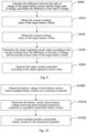
- the battery clusters are also detected and compensated before the battery clusters in the battery system are powered on, so as to avoids circulating current in the battery system, as shown in Fig. 10 , including:
- each battery cluster may have a certain battery voltage.
- the batteries in the battery cluster store a certain amount of electric energy but have not exhausted it.
- the control unit can obtain the battery voltage of each battery cluster, and determines the battery cluster whose battery voltage meets the preset parallel connection conditions as a parallel-connectable battery cluster based on the battery voltage of each battery cluster, and then controls multiple parallel-connectable battery clusters to be connected in parallel.
- the battery clusters that meet the preset parallel conditions are determined as parallel battery clusters, so that all the parallel-connectable battery clusters are connected in parallel to avoid the circulating current caused by the parallel connection of battery clusters with significant SOC differences when powered on, thereby improving the reliability of the battery system.
- the parallel-connectable battery cluster may be determined by the following method.
- Step S1100 Determine all battery clusters with a difference between the battery voltage and the target battery voltage less than the first preset voltage threshold as the parallel-connectable battery clusters.
- Step S1120 Control the first power converter to perform voltage compensation on the candidate parallel-connectable battery cluster, so that the candidate parallelizable battery cluster becomes a parallel-connectable battery cluster.
- a first preset voltage threshold UA and a second preset voltage threshold UB can be configured in advance in this solution, where the second voltage threshold UB is greater than the first voltage threshold UA, and the second voltage threshold UB can be determined based on the voltage regulation ability of the first power converter.
- the battery cluster is determined as a parallel-connectable battery cluster
- the voltage difference between the battery voltage of the battery cluster and the target battery voltage is greater than the first preset voltage threshold UA, it is determined whether the voltage difference between the battery voltage of the battery cluster and the target battery voltage is less than the second preset voltage threshold UB. If it is less than the second preset voltage threshold UB, as the first power converter can only compensate for one battery cluster, the battery voltage of the battery cluster can approach the target battery voltage and thus participate in parallel connection.
- the battery cluster is determined as the candidate parallel-connectable battery cluster, and thus the first power converter is controlled to compensate for the voltage of the candidate parallel-connectable battery cluster, so as to make it the parallel-connectable battery cluster.
- the battery cluster will be listed as non-parallel.
- Fig. 12 shows a structural schematic block diagram of a regulating device provided in the present disclosure. It should be understood that the device corresponds to the method embodiments performed in Figs. 6 to 11 and can perform the steps involved in the aforementioned method. The specific functions of the device can be found in the above description. To avoid repetition, detailed descriptions are appropriately omitted here.
- the device includes at least one software functional module that can be stored in memory in the form of software or firmware or solidified in the operating system (OS) of the device.
- OS operating system
- the device includes: a control module 1200, configured to disconnect the parallel connection between the target battery cluster and other battery clusters, and controlling the connection between the target battery cluster and the first power converter to conduct; a sending module 1210, configured to send a target current command to the first power converter to regulate the target battery cluster based on the target current command through the first power converter.
- the control module controls the parallel connection between the target battery cluster and other battery clusters, and the connection between the target battery cluster and the first power converter is controlled to conduct.
- the target current command is sent to the first power converter by the sending module, so that the target battery cluster is regulated by the first power converter according to the target current command, making the state of charge of the target battery cluster close to the target charge state, that is, close to the state of charge of other battery clusters, thereby eliminating the difference of the state of charge between the target battery cluster and other battery clusters, so as to improve the constant power operation ability of the energy storage system.
- the device further includes: a collection module 1220, configured to collect the state of charge of each battery cluster; a determination module 1230, configured to compare the state of charge of each battery cluster with the target state of charge, and determine the battery cluster whose state of charge has a preset relationship with the target state of charge as the target battery cluster.
- the determination module 1230 is specifically configured to determine the battery cluster with the largest absolute value of the difference between the state of charge and the target state of charge as the target battery cluster.
- the device further includes: a calculation module 1240, configured to calculate the difference between the state of charge of the target battery cluster and the target state of charge, and obtain the difference in state of charge; calculate the present current value of the target battery cluster; and calculate the target regulated current value according to the difference of the state of charge and the present current value; a generation module 1250, configured to generate a target current command according to the target regulated current value.
- a calculation module 1240 configured to calculate the difference between the state of charge of the target battery cluster and the target state of charge, and obtain the difference in state of charge
- calculate the present current value of the target battery cluster and calculate the target regulated current value according to the difference of the state of charge and the present current value
- a generation module 1250 configured to generate a target current command according to the target regulated current value.
- the calculation module 1240 is further configured to calculate the difference between the state of charge of the target battery cluster and the target state of charge, and obtain the difference of the state of charge; calculate the present current value of the target battery cluster; the device further includes an acquisition module 1260, configured to obtain a current working status of the battery system; the determination module 1230 is further configured to determine the target regulated current value according to the current working status, the difference of the state of charge, and the present current value of the target battery cluster; the generation module 1240 is further configured to generate the target current commend according to the target regulated current value.
- the determination module 1230 is specifically configured to determine the target regulating coefficient according to the current working status and the difference of the state of charge; and calculate the product of the target regulating coefficient and the present current value of the target battery cluster, and obtain the target regulated current value.
- the determination module 1230 is further specifically configured to: determine the target regulating coefficient as the first preset coefficient when the current working status of the battery system is charging and the difference of the state of charge is greater than 0; determine the target regulating coefficient as the second preset coefficient when the current working status of the battery system is charging and the difference of the state of charge is less than 0; determine the target regulating coefficient as the third preset coefficient, when the current working status of the battery system is discharge and the difference of the state of charge is greater than 0; determine the target regulating coefficient as the fourth preset coefficient, when the current working status of the battery system is discharge and the difference of the state of charge is less than 0; herein, the first and fourth preset coefficients are less than 1, and the second and third preset coefficients are greater than 1.
- the acquisition module 1260 is further configured to acquire the battery voltage of each battery cluster before multiple battery clusters are connected in parallel; the determination module 1230 is further configured to determine each battery cluster whose battery voltage has a preset relationship with the target battery voltage as a parallel-connectable battery cluster; and the control module 1200 is further configured to control multiple parallel-connectable battery clusters to connect in parallel.
- the determination module 1230 is further specifically configured to: determine all the battery clusters with a difference between the battery voltage and the target battery voltage less than the first preset voltage threshold as the parallel-connectable battery clusters; determine, from the battery clusters, a candidate parallel-connectable battery cluster with a difference between the battery voltage and the target battery voltage greater than the first preset voltage threshold and less than the second preset voltage threshold; and control the first power converter to perform voltage compensation on the candidate parallel-connectable battery cluster, so that the candidate parallel-connectable battery cluster becomes a parallel-connectable battery cluster.
- the determination module 1230 is further specifically configured to: determine, if there are one battery cluster with a difference between the battery voltage and the target battery voltage greater than the first preset voltage threshold and less than the second preset voltage threshold, the battery cluster with a difference between the battery voltage and the target battery voltage greater than the first preset voltage threshold and less than the second preset voltage threshold as the candidate parallel-connectable battery cluster; determine, if there are a plurality of battery clusters with a difference between the battery voltage and the target battery voltage greater than the first preset voltage threshold and less than the second preset voltage threshold, the battery cluster with the smallest difference between the battery voltage and the target battery voltage as the candidate parallel-connectable battery cluster among the plurality of battery clusters with a difference between the battery voltage and the target battery voltage greater than the first preset voltage threshold and less than the second preset voltage threshold.
- the present disclosure provides an electronic equipment 13, including: a processor 1301 and a memory 1302.
- the processor 1301 and the memory 1302 are interconnected and communicate with each other through a communication bus 1303 and/or other forms of connection mechanism (not shown), and the memory 1302 stores a computer program executable by the processor 1301.
- the processor 1301 executes the computer program to perform any optional implementation mode on the external end machine during execution, such as steps S600 to S610: disconnect the parallel connection between the target battery cluster and other battery clusters, and control the connection between the target battery cluster and the first power converter to conduct; and send a target current command to the first power converter to regulate the target battery cluster according to the target current command.
- the present disclosure provides a computer-readable storage medium on which a computer program is stored, and the computer program, when executed by a processor, performs the method in any of the aforementioned optional implementation modes.
- the storage medium can be implemented by any type of volatile or non-volatile storage device or their combination, such as Static Random Access Memory (SRAM), Electrically Erasable Programmable Read-Only Memory (EEPROM), Erasable Programmable Read Only Memory (EPROM), Programmable Read-Only Memory (PROM), Read-Only Memory (ROM), magnetic memory, flash memory, magnetic disk or optical disc.
- SRAM Static Random Access Memory
- EEPROM Electrically Erasable Programmable Read-Only Memory
- EPROM Erasable Programmable Read Only Memory
- PROM Programmable Read-Only Memory
- ROM Read-Only Memory
- magnetic memory flash memory
- flash memory magnetic disk or optical disc.
- the present disclosure provides a computer program product that, when running on a computer, causes the computer to execute any method in any optional implementation modes.
Landscapes
- Engineering & Computer Science (AREA)
- Chemical & Material Sciences (AREA)
- Chemical Kinetics & Catalysis (AREA)
- Electrochemistry (AREA)
- General Chemical & Material Sciences (AREA)
- Manufacturing & Machinery (AREA)
- Microelectronics & Electronic Packaging (AREA)
- Charge And Discharge Circuits For Batteries Or The Like (AREA)
- Power Engineering (AREA)
Applications Claiming Priority (2)
| Application Number | Priority Date | Filing Date | Title |
|---|---|---|---|
| CN202210654627.3A CN115800414B (zh) | 2022-06-10 | 2022-06-10 | 调节系统及其储能系统、调节方法 |
| PCT/CN2023/082327 WO2023236616A1 (zh) | 2022-06-10 | 2023-03-17 | 调节系统及其储能系统、调节方法 |
Publications (2)
| Publication Number | Publication Date |
|---|---|
| EP4539293A1 true EP4539293A1 (de) | 2025-04-16 |
| EP4539293A4 EP4539293A4 (de) | 2025-12-03 |
Family
ID=85431188
Family Applications (1)
| Application Number | Title | Priority Date | Filing Date |
|---|---|---|---|
| EP23818784.3A Pending EP4539293A4 (de) | 2022-06-10 | 2023-03-17 | Anpassungssystem, energiespeichersystem dafür und anpassungsverfahren dafür |
Country Status (5)
| Country | Link |
|---|---|
| US (1) | US20250079871A1 (de) |
| EP (1) | EP4539293A4 (de) |
| JP (1) | JP2025515905A (de) |
| CN (1) | CN115800414B (de) |
| WO (1) | WO2023236616A1 (de) |
Families Citing this family (6)
| Publication number | Priority date | Publication date | Assignee | Title |
|---|---|---|---|---|
| CN115800414B (zh) * | 2022-06-10 | 2023-11-24 | 宁德时代新能源科技股份有限公司 | 调节系统及其储能系统、调节方法 |
| CN116054355B (zh) * | 2023-03-29 | 2023-08-04 | 深圳市首航新能源股份有限公司 | 一种储能系统及其电网系统 |
| CN116317003A (zh) * | 2023-03-31 | 2023-06-23 | 阳光储能技术有限公司 | 一种储能系统及其控制方法 |
| CN116566010B (zh) * | 2023-05-18 | 2024-01-30 | 中国华能集团清洁能源技术研究院有限公司 | 多电池簇的电压分配方法及装置 |
| CN117411152B (zh) * | 2023-12-15 | 2024-04-12 | 宁德时代新能源科技股份有限公司 | 储能系统的控制方法、控制装置和计算机可读存储介质 |
| CN117698508B (zh) * | 2024-01-23 | 2024-08-13 | 吉林大学 | 可变压的电动汽车电池包、电池控制系统及其反向供电方法 |
Family Cites Families (14)
| Publication number | Priority date | Publication date | Assignee | Title |
|---|---|---|---|---|
| JP4572850B2 (ja) * | 2006-03-24 | 2010-11-04 | 株式会社日立製作所 | 電源制御装置 |
| JP5017009B2 (ja) * | 2007-07-30 | 2012-09-05 | 株式会社東芝 | 並列接続蓄電システム |
| US20100213897A1 (en) * | 2009-02-23 | 2010-08-26 | Lawrence Tze-Leung Tse | Battery-Cell Converter Management Systems |
| US11557796B2 (en) * | 2019-07-23 | 2023-01-17 | Cummins Inc. | DC-DC-converter-based active voltage-balancing system and method for parallel battery packs |
| JP7299095B2 (ja) * | 2019-07-30 | 2023-06-27 | 東芝三菱電機産業システム株式会社 | 無停電電源装置 |
| WO2021149299A1 (ja) * | 2020-01-23 | 2021-07-29 | 三洋電機株式会社 | 電源装置とこの電源装置を備える電動車両及び蓄電装置 |
| CN113949111B (zh) * | 2020-07-15 | 2024-01-30 | 华为数字能源技术有限公司 | 储能系统 |
| CN112467839B (zh) * | 2020-11-23 | 2023-09-29 | 阳光电源股份有限公司 | 一种电池簇管理装置及电池储能系统 |
| CN113437780B (zh) * | 2021-07-30 | 2024-04-12 | 阳光电源股份有限公司 | 一种电池簇均衡储能系统及其控制方法 |
| CN215870854U (zh) * | 2021-08-30 | 2022-02-18 | 阳光储能技术有限公司 | 一种电池簇均衡储能系统 |
| CN113517747B (zh) * | 2021-08-30 | 2024-02-23 | 阳光储能技术有限公司 | 一种电池簇均衡储能系统及其控制方法 |
| CN114362288B (zh) * | 2021-12-08 | 2024-02-23 | 深圳市科陆电子科技股份有限公司 | 电池簇间均衡调节方法、系统及存储介质 |
| CN114583807B (zh) * | 2022-05-09 | 2022-10-14 | 宁德时代新能源科技股份有限公司 | 储能系统的控制方法、装置、设备、存储介质和程序产品 |
| CN115800414B (zh) * | 2022-06-10 | 2023-11-24 | 宁德时代新能源科技股份有限公司 | 调节系统及其储能系统、调节方法 |
-
2022
- 2022-06-10 CN CN202210654627.3A patent/CN115800414B/zh active Active
-
2023
- 2023-03-17 EP EP23818784.3A patent/EP4539293A4/de active Pending
- 2023-03-17 WO PCT/CN2023/082327 patent/WO2023236616A1/zh not_active Ceased
- 2023-03-17 JP JP2024568115A patent/JP2025515905A/ja active Pending
-
2024
- 2024-11-15 US US18/949,740 patent/US20250079871A1/en active Pending
Also Published As
| Publication number | Publication date |
|---|---|
| US20250079871A1 (en) | 2025-03-06 |
| WO2023236616A1 (zh) | 2023-12-14 |
| CN115800414B (zh) | 2023-11-24 |
| JP2025515905A (ja) | 2025-05-20 |
| EP4539293A4 (de) | 2025-12-03 |
| CN115800414A (zh) | 2023-03-14 |
Similar Documents
| Publication | Publication Date | Title |
|---|---|---|
| EP4539293A1 (de) | Anpassungssystem, energiespeichersystem dafür und anpassungsverfahren dafür | |
| US11292360B2 (en) | Battery equalization method and system, vehicle, storage medium, and electronic device | |
| US12003130B2 (en) | Energy storage system | |
| EP4496169A1 (de) | Batterieverwaltungsverfahren und -vorrichtung, batteriesystem und computerlesbares speichermedium | |
| EP3498521A1 (de) | Elektrofahrzeugenergieverwaltungssystem, steuerungsverfahren dafür und elektrofahrzeug | |
| CN115800415B (zh) | 一种电池管理方法、系统、电池系统及电子设备 | |
| EP3678276A1 (de) | Batterieausgleichssystem, fahrzeug, batterieausgleichsverfahren und speichermedium | |
| KR102822114B1 (ko) | 동력 전지의 충전 방법, 충전 장치 및 충전 시스템 | |
| US20220255327A1 (en) | Decentralized active equalization method for cascaded lithium-ion battery pack | |
| CN112993418B (zh) | 储能系统 | |
| JP7773678B1 (ja) | マルチマシン並列エネルギー貯蔵システム及びその充放電制御方法 | |
| WO2022198635A1 (zh) | 储能系统及其控制方法 | |
| JP2023535099A (ja) | 充放電装置、電池の充電及び放電方法、並びに充放電システム | |
| CN115152122A (zh) | 一种充电柜、电池包及充电系统 | |
| US20250112486A1 (en) | Energy storage system and energy storage system control method | |
| CN113783265A (zh) | 电池阵列的管理系统和管理方法 | |
| CN114362288A (zh) | 电池簇间均衡调节方法、系统及存储介质 | |
| CN103227487A (zh) | 电动自行车用燃料电池/锂离子电池混合动力能量管理系统 | |
| CN117175642A (zh) | 储能系统充放电控制方法、装置、电子设备及系统 | |
| CN110707679B (zh) | 电压控制方法及光伏供电装置、系统 | |
| JP7574309B2 (ja) | エネルギー貯蔵システム | |
| CN114243822A (zh) | 电池簇间均衡调节系统 | |
| CN115395118A (zh) | 电池包充电平衡控制方法、装置、电池管理系统及介质 | |
| KR102891862B1 (ko) | 에너지 저장 장치의 밸런싱 방법 | |
| CN113612277A (zh) | 一种电池单元及其控制方法 |
Legal Events
| Date | Code | Title | Description |
|---|---|---|---|
| STAA | Information on the status of an ep patent application or granted ep patent |
Free format text: STATUS: THE INTERNATIONAL PUBLICATION HAS BEEN MADE |
|
| PUAI | Public reference made under article 153(3) epc to a published international application that has entered the european phase |
Free format text: ORIGINAL CODE: 0009012 |
|
| STAA | Information on the status of an ep patent application or granted ep patent |
Free format text: STATUS: REQUEST FOR EXAMINATION WAS MADE |
|
| 17P | Request for examination filed |
Effective date: 20250110 |
|
| AK | Designated contracting states |
Kind code of ref document: A1 Designated state(s): AL AT BE BG CH CY CZ DE DK EE ES FI FR GB GR HR HU IE IS IT LI LT LU LV MC ME MK MT NL NO PL PT RO RS SE SI SK SM TR |
|
| DAV | Request for validation of the european patent (deleted) | ||
| DAX | Request for extension of the european patent (deleted) | ||
| A4 | Supplementary search report drawn up and despatched |
Effective date: 20251030 |
|
| RIC1 | Information provided on ipc code assigned before grant |
Ipc: H02J 7/00 20060101AFI20251024BHEP Ipc: H01M 10/42 20060101ALI20251024BHEP Ipc: H01M 10/44 20060101ALI20251024BHEP Ipc: H01M 50/512 20210101ALI20251024BHEP |