EP4538457A1 - Piquet de clôture pour une entretoise de clôture formée de plusieurs tels piquets de clôture, entretoise de clôture pour une clôture de protection de voie et système de clôture de voie - Google Patents
Piquet de clôture pour une entretoise de clôture formée de plusieurs tels piquets de clôture, entretoise de clôture pour une clôture de protection de voie et système de clôture de voie Download PDFInfo
- Publication number
- EP4538457A1 EP4538457A1 EP24203963.4A EP24203963A EP4538457A1 EP 4538457 A1 EP4538457 A1 EP 4538457A1 EP 24203963 A EP24203963 A EP 24203963A EP 4538457 A1 EP4538457 A1 EP 4538457A1
- Authority
- EP
- European Patent Office
- Prior art keywords
- fence
- pole
- strut
- connector
- tube
- Prior art date
- Legal status (The legal status is an assumption and is not a legal conclusion. Google has not performed a legal analysis and makes no representation as to the accuracy of the status listed.)
- Pending
Links
Images


Classifications
-
- E—FIXED CONSTRUCTIONS
- E01—CONSTRUCTION OF ROADS, RAILWAYS, OR BRIDGES
- E01B—PERMANENT WAY; PERMANENT-WAY TOOLS; MACHINES FOR MAKING RAILWAYS OF ALL KINDS
- E01B26/00—Tracks or track components not covered by any one of the preceding groups
- E01B26/005—Means for fixing posts, barriers, fences or the like to rails
-
- B—PERFORMING OPERATIONS; TRANSPORTING
- B61—RAILWAYS
- B61L—GUIDING RAILWAY TRAFFIC; ENSURING THE SAFETY OF RAILWAY TRAFFIC
- B61L29/00—Safety means for rail/road crossing traffic
- B61L29/02—Guards or obstacles for preventing access to the route
-
- F—MECHANICAL ENGINEERING; LIGHTING; HEATING; WEAPONS; BLASTING
- F16—ENGINEERING ELEMENTS AND UNITS; GENERAL MEASURES FOR PRODUCING AND MAINTAINING EFFECTIVE FUNCTIONING OF MACHINES OR INSTALLATIONS; THERMAL INSULATION IN GENERAL
- F16B—DEVICES FOR FASTENING OR SECURING CONSTRUCTIONAL ELEMENTS OR MACHINE PARTS TOGETHER, e.g. NAILS, BOLTS, CIRCLIPS, CLAMPS, CLIPS OR WEDGES; JOINTS OR JOINTING
- F16B2/00—Friction-grip releasable fastenings
- F16B2/02—Clamps, i.e. with gripping action effected by positive means other than the inherent resistance to deformation of the material of the fastening
- F16B2/06—Clamps, i.e. with gripping action effected by positive means other than the inherent resistance to deformation of the material of the fastening external, i.e. with contracting action
- F16B2/065—Clamps, i.e. with gripping action effected by positive means other than the inherent resistance to deformation of the material of the fastening external, i.e. with contracting action using screw-thread elements
-
- F—MECHANICAL ENGINEERING; LIGHTING; HEATING; WEAPONS; BLASTING
- F16—ENGINEERING ELEMENTS AND UNITS; GENERAL MEASURES FOR PRODUCING AND MAINTAINING EFFECTIVE FUNCTIONING OF MACHINES OR INSTALLATIONS; THERMAL INSULATION IN GENERAL
- F16B—DEVICES FOR FASTENING OR SECURING CONSTRUCTIONAL ELEMENTS OR MACHINE PARTS TOGETHER, e.g. NAILS, BOLTS, CIRCLIPS, CLAMPS, CLIPS OR WEDGES; JOINTS OR JOINTING
- F16B7/00—Connections of rods or tubes, e.g. of non-circular section, mutually, including resilient connections
- F16B7/04—Clamping or clipping connections
- F16B7/0406—Clamping or clipping connections for rods or tubes being coaxial
- F16B7/0413—Clamping or clipping connections for rods or tubes being coaxial for tubes using the innerside thereof
- F16B7/042—Clamping or clipping connections for rods or tubes being coaxial for tubes using the innerside thereof with a locking element, e.g. pin, ball or pushbutton, engaging in a hole in the wall of at least one tube
-
- F—MECHANICAL ENGINEERING; LIGHTING; HEATING; WEAPONS; BLASTING
- F16—ENGINEERING ELEMENTS AND UNITS; GENERAL MEASURES FOR PRODUCING AND MAINTAINING EFFECTIVE FUNCTIONING OF MACHINES OR INSTALLATIONS; THERMAL INSULATION IN GENERAL
- F16B—DEVICES FOR FASTENING OR SECURING CONSTRUCTIONAL ELEMENTS OR MACHINE PARTS TOGETHER, e.g. NAILS, BOLTS, CIRCLIPS, CLAMPS, CLIPS OR WEDGES; JOINTS OR JOINTING
- F16B7/00—Connections of rods or tubes, e.g. of non-circular section, mutually, including resilient connections
- F16B7/04—Clamping or clipping connections
- F16B7/044—Clamping or clipping connections for rods or tubes being in angled relationship
- F16B7/048—Clamping or clipping connections for rods or tubes being in angled relationship for rods or for tubes without using the innerside thereof
- F16B7/0493—Clamping or clipping connections for rods or tubes being in angled relationship for rods or for tubes without using the innerside thereof forming a crossed-over connection
-
- E—FIXED CONSTRUCTIONS
- E01—CONSTRUCTION OF ROADS, RAILWAYS, OR BRIDGES
- E01B—PERMANENT WAY; PERMANENT-WAY TOOLS; MACHINES FOR MAKING RAILWAYS OF ALL KINDS
- E01B17/00—Cattle guards connected to the permanent way
-
- E—FIXED CONSTRUCTIONS
- E04—BUILDING
- E04H—BUILDINGS OR LIKE STRUCTURES FOR PARTICULAR PURPOSES; SWIMMING OR SPLASH BATHS OR POOLS; MASTS; FENCING; TENTS OR CANOPIES, IN GENERAL
- E04H17/00—Fencing, e.g. fences, enclosures, corrals
- E04H17/14—Fences constructed of rigid elements, e.g. with additional wire fillings or with posts
- E04H17/1413—Post-and-rail fences, e.g. without vertical cross-members
- E04H17/1447—Details of connections between rails and posts
- E04H17/146—Details of connections between rails and posts the rails being attached to the front faces of the posts
-
- E—FIXED CONSTRUCTIONS
- E04—BUILDING
- E04H—BUILDINGS OR LIKE STRUCTURES FOR PARTICULAR PURPOSES; SWIMMING OR SPLASH BATHS OR POOLS; MASTS; FENCING; TENTS OR CANOPIES, IN GENERAL
- E04H17/00—Fencing, e.g. fences, enclosures, corrals
- E04H17/14—Fences constructed of rigid elements, e.g. with additional wire fillings or with posts
- E04H17/1413—Post-and-rail fences, e.g. without vertical cross-members
- E04H17/1447—Details of connections between rails and posts
- E04H17/1488—Brackets for connections between rails and posts
Definitions
- track protection fences or track bed protection fences are used in railway traffic to prevent unwanted intrusion into a track area, for example, an intrusion into the area of a track that is still in use.
- a track protection fence system comprising a track protection fence having at least one fence strut is known.
- the track protection fence is attached to a track system, specifically to a rail of the track system, via track protection fence holding systems.
- the track protection fence holding system comprises a fence holder for holding the at least one fence strut, a fastening element that can be fastened to a track system, and a fixing system for fixing the fence holder to the fastening element.
- the fence struts forming the track protection fence are each formed by a plurality of bars, with adjacent bars being connected to one another by a bar connector that is inserted into the mutually facing ends of the bars.
- the stiles or fence posts are usually connected one after the other by inserting a stile connector into the preceding stile and attaching the subsequent stile onto the stile connector. Accordingly, the stiles are usually separated step by step. Connecting and disconnecting stiles arranged centrally within a fence strut, for example, to temporarily create access to a safety-critical area at one point on the rail fence, is problematic and complex. This is especially true since adjacent stiles are subject to a Displacement of the beams to be separated in the axial direction, i.e. along the longitudinal axis of the fence strut.
- the fence post according to the invention for a fence strut of a railway track protection fence formed from several such fence posts comprises a fence tube (or fence post tube) and a post connector, wherein the post connector is arranged at a first end of the fence tube so as to be displaceable between an extended coupling position for connection to an adjacent fence post and a release position retracted into the fence tube for releasing adjacent fence posts of a fence strut.
- the (elongated) fence tubes are preferably tubes with a substantially round or rectangular, in particular square, cross-section.
- the post connector is guided internally at the first end of the fence tube.
- the post connector is moved axially, i.e. parallel to the longitudinal axis of the fence tube or fence post.
- the post connector For connection to an adjacent fence post, the post connector is inserted in the coupling position into an end of the adjacent fence post designed to receive the post connector.
- the inventive design allows the fence poles to be connected and released without axial displacement of the fence poles to be connected or separated. Specifically, to release two connected fence poles, the pole connector connecting the fence poles is moved into the retracted release position. This allows the fence poles to be separated, in particular, moved against each other transversely to the longitudinal axis of the fence brace. The release of these now separated fence poles from the the other end of the fence post connected to the remainder of the fence strut, i.e.
- the fence tube has a connecting section at a second end, in particular a connecting section that is tapered compared to the rest of the fence tube, i.e. a connecting section with a reduced size or diameter, or alternatively a widened connecting section, for connection to the pole connector of an adjacent, similar fence pole.
- the connecting section is preferably designed for inserting the pole connector of an adjacent fence pole, in particular for positively receiving the pole connector.
- these receiving openings are preferably arranged concentrically or one above the other.
- a securing element for example a securing pin, can be inserted into the receiving openings arranged one above the other. This ensures a secure connection of adjacent fence poles, in particular unwanted lateral movement or a moving apart and the resulting loosening of adjacent fence poles is reliably prevented.
- the pole connector has an engagement section which preferably has a smaller dimension than the rest of the pole connector, specifically a smaller (outer) diameter.
- the engagement section engages in the connecting section of an adjacent fence pole.
- the transition from the engagement section to the rest of the pole connector is preferably formed by a shoulder.
- the outer edge of the connecting section preferably rests on the shoulder.
- the penetration depth of the pole connector is limited by the shoulder resting on the outer edge.
- the aforementioned embodiment can also ensure that receiving openings in the engagement area of the pole connector and receiving openings in the connecting section for introducing a securing element are arranged in a correspondingly superimposed position.
- the pole connector is fully or at least almost fully inserted into the fence tube in the release position.
- the release position of the pole connector does not impede the connection or disconnection of two fence poles.
- an actuating element connected to the rod connector is provided for the manual displacement of the rod connector from the Coupling position into the release position and/or from the release position into the coupling position.
- the rod connector can preferably be moved directly via the actuating element. No further, in particular special, tool is required for this.
- the actuating element enables a user to easily move the rod connector from the coupling position to the release position and vice versa.
- the actuating element is particularly preferably guided in a guide slot in the fence tube.
- the actuating element is guided outwards, in particular from the rod connector arranged displaceably inside the fence tube, through the guide slot.
- the guide slot is preferably designed as an elongated hole extending along the longitudinal axis of the fence tube or fence rod.
- the guide slot in particular by the actuating element bearing against the ends of the guide slot, can limit the displacement path of the actuating element and thus any displacement of the rod connector. In particular, displacement of the rod connector beyond the coupling position and/or the release position can be prevented.
- the disclosure also relates to a fence post for a fence strut of a railway protection fence formed from a plurality of such fence posts, wherein the fence post has a pole connector which is arranged at a first end of the fence post and is displaceable between an extended coupling position for connection to an adjacent fence post and a release position retracted into the fence post for releasing adjacent fence posts of a fence strut.
- the pole connector is displaceable, in particular parallel to a longitudinal axis of the pole connector, between the coupling position and the release position.
- the fence post has a connecting section at a second end, in particular a connecting section with a reduced or widened dimension, for connection to the pole connector of an adjacent, similar fence post, wherein the connecting section is designed, in particular, for introducing the pole connector of an adjacent fence post.
- the connecting section is designed, in particular, for introducing the pole connector of an adjacent fence post.
- the fence pole mentioned can have a limiting element, in particular a limiting pin introduced into the fence pole, and a spring element arranged between the limiting element and the pole connector.
- the pole connector of the fence pole mentioned is completely inserted into the fence pole in the release position.
- the fence pole mentioned has a guide slot described above for guiding an actuating element connected to the pole connector for displacing the pole connector.
- the above statements apply accordingly to the aforementioned fence post.
- a fence brace with several such interconnectable or connected fence posts, as well as a railroad safety fence system comprising such a fence brace and the aforementioned railroad safety fence support system are the subject of the disclosure.
- the exemplary rail protection fence shown is formed by three fence struts 7 arranged one above the other, which are held by correspondingly arranged suspensions 8 of the fence brackets 6.
- the exemplary fence brackets 6 are, as in particular also in Fig. 2 shown, each composed of several vertical struts, which are inserted and guided into one another and can be fixed in their position relative to one another by means of fixing means, here using wing screws.
- the attachment of the suspensions 8 to the vertical struts of the fence bracket 6 can be done, for example, by welding or screwing.
- the fence struts 7 which can be arranged in the suspensions 8 are each composed of interconnected fence poles 9 which are described in detail below.
- the uppermost fence strut 7 is in Fig. 1 incomplete or with only one fence post 9. Accordingly, in Fig. 2
- the uppermost suspension 8 of the fence bracket 6 is shown without a fence pole 9 inserted into it.
- the fence poles 9 have a round cross-section, although other designs are also possible in principle.
- Fig. 3 shows a suspension 8 of the fence bracket 6 from Fig. 1 and Fig. 2 in an enlarged view.
- the suspension 8 comprises a pole holder 10 which is adapted to the outer contour of the fence pole 9 and is open at the top, a rotatably mounted clamping block 11 and a wing nut 23 arranged in a threaded holder.
- the fixing of a fence pole 9 inserted into the pole holder 10 from above is achieved by screwing the wing nut 23 in the direction of the pole holder 10.
- the front end of the wing nut 23 presses against the clamping block 11 so that the latter comes into contact with the fence pole 9 inserted into the pole holder 10 and clamps it in the pole holder 10.
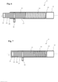
- a particularly electrically insulating pole connector 13 is arranged at the left end of the fence pole 9 or the fence tube 12, shown in detail.
- the pole connector 13 is arranged between a Fig. 6 shown extended coupling position, via which the fence pole 9 can be connected to an adjacent fence pole 9, and one in Fig. 7 shown release position, in which the pole connector 13 is fully inserted into the fence tube 12, along or parallel to a longitudinal axis L of the fence tube 12 or the fence pole 9, displaceably guided in the fence tube 12.
- the pole connector 13 is pretensioned by a spring element 14 arranged in the fence tube 12 in the coupling position forming the basic position.
- the spring element 14 rests with one side on the inner end of the pole connector 13 lying in the fence tube 12 and with its other side on a limiting element 15 arranged in the fence tube 12.
- the limiting element 15 of the shown embodiment is specifically, as also in Fig. 4 is sketched, formed by a boundary pin inserted through the side wall of the fence tube 12.
- the rod connector 13 Via an actuating element 16 connected to the rod connector 13, the rod connector 13 can be moved from the Fig. 6 shown coupling position against the action of the spring element 14 into the Fig. 7
- the actuating element 16 of the exemplary embodiment shown is designed as an actuating pin inserted into a receptacle of the rod connector 13, wherein the actuating pin is guided outwards through a guide slot 17 of the fence tube 12 extending along the longitudinal axis L of the fence rod 9.
- the actuating element 16 resting against the longitudinal ends of the guide slot 17, the displacement path of the rod connector 13 is limited.
- the positions in which the actuating element 16 rests against the longitudinal ends of the guide slot 17 represent the coupling position and the release position, respectively, in the exemplary embodiment shown.
- the fence tube 12 has Fig. 4 and Fig. 5 shown right end a connecting section 18.
- the connecting section 18 has a reduced diameter compared to the rest of the fence tube 12.
- An engagement section 19 of the rod connector 13, which protrudes outwards in the coupling position, can be introduced into the connecting section 18.
- the engagement section 19 has a reduced diameter compared to the rest of the rod connector 13, forming a shoulder 20, wherein the outer diameter of the engagement region 19 substantially corresponds to the inner diameter of the connecting section 18.
- the connecting section 18 and the engagement region 19 of the rod connector 13 further have receiving openings 21, 24, into which, as described below with reference to Fig. 10 described in more detail, a securing element 22 can be inserted to secure the connection of adjacent fence poles 9.
- FIG. 8 The connection of two adjacent fence poles 9, 9', specifically the connection of the pole connector 13 of a first fence pole 9 with a connecting section 18' of a second fence pole 9', is outlined.
- the rod connector 13 of the first fence rod 9 is first moved into the release position via the actuating element 16, and the connecting section 18' of the second fence rod 9' and the end of the first fence rod 9 having the rod connector 13 are positioned adjacent to one another.
- the rod connector 13, as shown in Fig. 9 shown then moved into the coupling position, whereby the engagement area 19 of the rod connector 13 is engaged in the connecting section 18 ⁇ of the Fig.
Landscapes
- Engineering & Computer Science (AREA)
- General Engineering & Computer Science (AREA)
- Mechanical Engineering (AREA)
- Architecture (AREA)
- Civil Engineering (AREA)
- Structural Engineering (AREA)
- Refuge Islands, Traffic Blockers, Or Guard Fence (AREA)
Applications Claiming Priority (1)
| Application Number | Priority Date | Filing Date | Title |
|---|---|---|---|
| DE102023128112.7A DE102023128112A1 (de) | 2023-10-13 | 2023-10-13 | Zaunstange für eine aus mehreren solcher Zaunstangen gebildete Zaunstrebe eines Gleisschutzzauns, Zaunstrebe für einen Gleisschutzzaun und Gleisschutzzaunsystem |
Publications (1)
| Publication Number | Publication Date |
|---|---|
| EP4538457A1 true EP4538457A1 (fr) | 2025-04-16 |
Family
ID=92966679
Family Applications (1)
| Application Number | Title | Priority Date | Filing Date |
|---|---|---|---|
| EP24203963.4A Pending EP4538457A1 (fr) | 2023-10-13 | 2024-10-01 | Piquet de clôture pour une entretoise de clôture formée de plusieurs tels piquets de clôture, entretoise de clôture pour une clôture de protection de voie et système de clôture de voie |
Country Status (2)
| Country | Link |
|---|---|
| EP (1) | EP4538457A1 (fr) |
| DE (1) | DE102023128112A1 (fr) |
Citations (3)
| Publication number | Priority date | Publication date | Assignee | Title |
|---|---|---|---|---|
| DE102005022316A1 (de) * | 2004-09-16 | 2006-03-23 | Hünnebeck Group GmbH | Pfosten zum Einsetzen in ein Anschlussstück |
| EP3421024B1 (fr) * | 2017-06-26 | 2020-01-08 | Winncare France | Montant telescopique de barriere de lit et lit medical comprenant une telle barriere |
| EP3936663A1 (fr) | 2020-07-08 | 2022-01-12 | ARC Allround Cleaning Rheinfelden AG | Système de clôture de protection de rail |
-
2023
- 2023-10-13 DE DE102023128112.7A patent/DE102023128112A1/de active Pending
-
2024
- 2024-10-01 EP EP24203963.4A patent/EP4538457A1/fr active Pending
Patent Citations (3)
| Publication number | Priority date | Publication date | Assignee | Title |
|---|---|---|---|---|
| DE102005022316A1 (de) * | 2004-09-16 | 2006-03-23 | Hünnebeck Group GmbH | Pfosten zum Einsetzen in ein Anschlussstück |
| EP3421024B1 (fr) * | 2017-06-26 | 2020-01-08 | Winncare France | Montant telescopique de barriere de lit et lit medical comprenant une telle barriere |
| EP3936663A1 (fr) | 2020-07-08 | 2022-01-12 | ARC Allround Cleaning Rheinfelden AG | Système de clôture de protection de rail |
Also Published As
| Publication number | Publication date |
|---|---|
| DE102023128112A1 (de) | 2025-04-17 |
Similar Documents
| Publication | Publication Date | Title |
|---|---|---|
| EP2443352B1 (fr) | Système de liaison de barres profilées | |
| EP0297033A2 (fr) | Elément de fixation pour une barre | |
| DE102020134286A1 (de) | Verbindungshülse | |
| EP3445935B1 (fr) | Installation de porte coulissante | |
| DE202017107404U1 (de) | Knotenverbinder für Profilsysteme oder dergleichen | |
| DE202014002813U1 (de) | Temporäre Wandstütze | |
| WO2018024447A1 (fr) | Élément de liaison | |
| DE10315690B4 (de) | Befestigungsvorrichtung für eine Anhängevorrichtung an einem Längsträger eines Kraftfahrzeuges | |
| DE102014110192A1 (de) | Befestiger für eine Montageschiene | |
| DE102009013981B4 (de) | Abstandshalter | |
| DE4239805C2 (de) | Verstrebungssystem | |
| EP0004374A1 (fr) | Moyen de liaison de deux profilés | |
| DE10225403B4 (de) | Ständerwerk | |
| DE10112035B4 (de) | Schutzzaun | |
| EP4538457A1 (fr) | Piquet de clôture pour une entretoise de clôture formée de plusieurs tels piquets de clôture, entretoise de clôture pour une clôture de protection de voie et système de clôture de voie | |
| EP1853827B1 (fr) | Connecteur de profiles | |
| DE102019130855A1 (de) | Verbindungssystem und Regalsystem | |
| DE3208576A1 (de) | Rohrverbindung | |
| DE202023105928U1 (de) | Zaunstange für eine aus mehreren solcher Zaunstangen gebildete Zaunstrebe eines Gleisschutzzauns, Zaunstrebe für einen Gleisschutzzaun und Gleisschutzzaunsystem | |
| EP1111141A2 (fr) | Garniture d'installation avec connection à manchon de raccordement détachable | |
| DE19841314A1 (de) | Vorrichtung zum Verbinden von zwei Rohren | |
| EP1760840B1 (fr) | Connecteur électrique et siège ayant un tel connecteur | |
| DE602004004485T2 (de) | Zaunpfähle | |
| DE202007015012U1 (de) | Schutzwandanordnung zum Begrenzen und Absichern von Fahrbahnen, insbesondere in Baustellenbereichen | |
| DE10051323B4 (de) | Abschleppstange |
Legal Events
| Date | Code | Title | Description |
|---|---|---|---|
| PUAI | Public reference made under article 153(3) epc to a published international application that has entered the european phase |
Free format text: ORIGINAL CODE: 0009012 |
|
| STAA | Information on the status of an ep patent application or granted ep patent |
Free format text: STATUS: THE APPLICATION HAS BEEN PUBLISHED |
|
| AK | Designated contracting states |
Kind code of ref document: A1 Designated state(s): AL AT BE BG CH CY CZ DE DK EE ES FI FR GB GR HR HU IE IS IT LI LT LU LV MC ME MK MT NL NO PL PT RO RS SE SI SK SM TR |
|
| STAA | Information on the status of an ep patent application or granted ep patent |
Free format text: STATUS: REQUEST FOR EXAMINATION WAS MADE |
|
| 17P | Request for examination filed |
Effective date: 20251016 |