EP4538457A1 - Fence bar for a fence strut of a track fence formed of a plurality of such fence bars, fence strut for a track fence and track fence system - Google Patents
Fence bar for a fence strut of a track fence formed of a plurality of such fence bars, fence strut for a track fence and track fence system Download PDFInfo
- Publication number
- EP4538457A1 EP4538457A1 EP24203963.4A EP24203963A EP4538457A1 EP 4538457 A1 EP4538457 A1 EP 4538457A1 EP 24203963 A EP24203963 A EP 24203963A EP 4538457 A1 EP4538457 A1 EP 4538457A1
- Authority
- EP
- European Patent Office
- Prior art keywords
- fence
- pole
- strut
- connector
- tube
- Prior art date
- Legal status (The legal status is an assumption and is not a legal conclusion. Google has not performed a legal analysis and makes no representation as to the accuracy of the status listed.)
- Pending
Links
Images


Classifications
-
- E—FIXED CONSTRUCTIONS
- E01—CONSTRUCTION OF ROADS, RAILWAYS, OR BRIDGES
- E01B—PERMANENT WAY; PERMANENT-WAY TOOLS; MACHINES FOR MAKING RAILWAYS OF ALL KINDS
- E01B26/00—Tracks or track components not covered by any one of the preceding groups
- E01B26/005—Means for fixing posts, barriers, fences or the like to rails
-
- B—PERFORMING OPERATIONS; TRANSPORTING
- B61—RAILWAYS
- B61L—GUIDING RAILWAY TRAFFIC; ENSURING THE SAFETY OF RAILWAY TRAFFIC
- B61L29/00—Safety means for rail/road crossing traffic
- B61L29/02—Guards or obstacles for preventing access to the route
-
- F—MECHANICAL ENGINEERING; LIGHTING; HEATING; WEAPONS; BLASTING
- F16—ENGINEERING ELEMENTS AND UNITS; GENERAL MEASURES FOR PRODUCING AND MAINTAINING EFFECTIVE FUNCTIONING OF MACHINES OR INSTALLATIONS; THERMAL INSULATION IN GENERAL
- F16B—DEVICES FOR FASTENING OR SECURING CONSTRUCTIONAL ELEMENTS OR MACHINE PARTS TOGETHER, e.g. NAILS, BOLTS, CIRCLIPS, CLAMPS, CLIPS OR WEDGES; JOINTS OR JOINTING
- F16B2/00—Friction-grip releasable fastenings
- F16B2/02—Clamps, i.e. with gripping action effected by positive means other than the inherent resistance to deformation of the material of the fastening
- F16B2/06—Clamps, i.e. with gripping action effected by positive means other than the inherent resistance to deformation of the material of the fastening external, i.e. with contracting action
- F16B2/065—Clamps, i.e. with gripping action effected by positive means other than the inherent resistance to deformation of the material of the fastening external, i.e. with contracting action using screw-thread elements
-
- F—MECHANICAL ENGINEERING; LIGHTING; HEATING; WEAPONS; BLASTING
- F16—ENGINEERING ELEMENTS AND UNITS; GENERAL MEASURES FOR PRODUCING AND MAINTAINING EFFECTIVE FUNCTIONING OF MACHINES OR INSTALLATIONS; THERMAL INSULATION IN GENERAL
- F16B—DEVICES FOR FASTENING OR SECURING CONSTRUCTIONAL ELEMENTS OR MACHINE PARTS TOGETHER, e.g. NAILS, BOLTS, CIRCLIPS, CLAMPS, CLIPS OR WEDGES; JOINTS OR JOINTING
- F16B7/00—Connections of rods or tubes, e.g. of non-circular section, mutually, including resilient connections
- F16B7/04—Clamping or clipping connections
- F16B7/0406—Clamping or clipping connections for rods or tubes being coaxial
- F16B7/0413—Clamping or clipping connections for rods or tubes being coaxial for tubes using the innerside thereof
- F16B7/042—Clamping or clipping connections for rods or tubes being coaxial for tubes using the innerside thereof with a locking element, e.g. pin, ball or pushbutton, engaging in a hole in the wall of at least one tube
-
- F—MECHANICAL ENGINEERING; LIGHTING; HEATING; WEAPONS; BLASTING
- F16—ENGINEERING ELEMENTS AND UNITS; GENERAL MEASURES FOR PRODUCING AND MAINTAINING EFFECTIVE FUNCTIONING OF MACHINES OR INSTALLATIONS; THERMAL INSULATION IN GENERAL
- F16B—DEVICES FOR FASTENING OR SECURING CONSTRUCTIONAL ELEMENTS OR MACHINE PARTS TOGETHER, e.g. NAILS, BOLTS, CIRCLIPS, CLAMPS, CLIPS OR WEDGES; JOINTS OR JOINTING
- F16B7/00—Connections of rods or tubes, e.g. of non-circular section, mutually, including resilient connections
- F16B7/04—Clamping or clipping connections
- F16B7/044—Clamping or clipping connections for rods or tubes being in angled relationship
- F16B7/048—Clamping or clipping connections for rods or tubes being in angled relationship for rods or for tubes without using the innerside thereof
- F16B7/0493—Clamping or clipping connections for rods or tubes being in angled relationship for rods or for tubes without using the innerside thereof forming a crossed-over connection
-
- E—FIXED CONSTRUCTIONS
- E01—CONSTRUCTION OF ROADS, RAILWAYS, OR BRIDGES
- E01B—PERMANENT WAY; PERMANENT-WAY TOOLS; MACHINES FOR MAKING RAILWAYS OF ALL KINDS
- E01B17/00—Cattle guards connected to the permanent way
-
- E—FIXED CONSTRUCTIONS
- E04—BUILDING
- E04H—BUILDINGS OR LIKE STRUCTURES FOR PARTICULAR PURPOSES; SWIMMING OR SPLASH BATHS OR POOLS; MASTS; FENCING; TENTS OR CANOPIES, IN GENERAL
- E04H17/00—Fencing, e.g. fences, enclosures, corrals
- E04H17/14—Fences constructed of rigid elements, e.g. with additional wire fillings or with posts
- E04H17/1413—Post-and-rail fences, e.g. without vertical cross-members
- E04H17/1447—Details of connections between rails and posts
- E04H17/146—Details of connections between rails and posts the rails being attached to the front faces of the posts
-
- E—FIXED CONSTRUCTIONS
- E04—BUILDING
- E04H—BUILDINGS OR LIKE STRUCTURES FOR PARTICULAR PURPOSES; SWIMMING OR SPLASH BATHS OR POOLS; MASTS; FENCING; TENTS OR CANOPIES, IN GENERAL
- E04H17/00—Fencing, e.g. fences, enclosures, corrals
- E04H17/14—Fences constructed of rigid elements, e.g. with additional wire fillings or with posts
- E04H17/1413—Post-and-rail fences, e.g. without vertical cross-members
- E04H17/1447—Details of connections between rails and posts
- E04H17/1488—Brackets for connections between rails and posts
Definitions
- track protection fences or track bed protection fences are used in railway traffic to prevent unwanted intrusion into a track area, for example, an intrusion into the area of a track that is still in use.
- a track protection fence system comprising a track protection fence having at least one fence strut is known.
- the track protection fence is attached to a track system, specifically to a rail of the track system, via track protection fence holding systems.
- the track protection fence holding system comprises a fence holder for holding the at least one fence strut, a fastening element that can be fastened to a track system, and a fixing system for fixing the fence holder to the fastening element.
- the fence struts forming the track protection fence are each formed by a plurality of bars, with adjacent bars being connected to one another by a bar connector that is inserted into the mutually facing ends of the bars.
- the stiles or fence posts are usually connected one after the other by inserting a stile connector into the preceding stile and attaching the subsequent stile onto the stile connector. Accordingly, the stiles are usually separated step by step. Connecting and disconnecting stiles arranged centrally within a fence strut, for example, to temporarily create access to a safety-critical area at one point on the rail fence, is problematic and complex. This is especially true since adjacent stiles are subject to a Displacement of the beams to be separated in the axial direction, i.e. along the longitudinal axis of the fence strut.
- the fence post according to the invention for a fence strut of a railway track protection fence formed from several such fence posts comprises a fence tube (or fence post tube) and a post connector, wherein the post connector is arranged at a first end of the fence tube so as to be displaceable between an extended coupling position for connection to an adjacent fence post and a release position retracted into the fence tube for releasing adjacent fence posts of a fence strut.
- the (elongated) fence tubes are preferably tubes with a substantially round or rectangular, in particular square, cross-section.
- the post connector is guided internally at the first end of the fence tube.
- the post connector is moved axially, i.e. parallel to the longitudinal axis of the fence tube or fence post.
- the post connector For connection to an adjacent fence post, the post connector is inserted in the coupling position into an end of the adjacent fence post designed to receive the post connector.
- the inventive design allows the fence poles to be connected and released without axial displacement of the fence poles to be connected or separated. Specifically, to release two connected fence poles, the pole connector connecting the fence poles is moved into the retracted release position. This allows the fence poles to be separated, in particular, moved against each other transversely to the longitudinal axis of the fence brace. The release of these now separated fence poles from the the other end of the fence post connected to the remainder of the fence strut, i.e.
- the fence tube has a connecting section at a second end, in particular a connecting section that is tapered compared to the rest of the fence tube, i.e. a connecting section with a reduced size or diameter, or alternatively a widened connecting section, for connection to the pole connector of an adjacent, similar fence pole.
- the connecting section is preferably designed for inserting the pole connector of an adjacent fence pole, in particular for positively receiving the pole connector.
- these receiving openings are preferably arranged concentrically or one above the other.
- a securing element for example a securing pin, can be inserted into the receiving openings arranged one above the other. This ensures a secure connection of adjacent fence poles, in particular unwanted lateral movement or a moving apart and the resulting loosening of adjacent fence poles is reliably prevented.
- the pole connector has an engagement section which preferably has a smaller dimension than the rest of the pole connector, specifically a smaller (outer) diameter.
- the engagement section engages in the connecting section of an adjacent fence pole.
- the transition from the engagement section to the rest of the pole connector is preferably formed by a shoulder.
- the outer edge of the connecting section preferably rests on the shoulder.
- the penetration depth of the pole connector is limited by the shoulder resting on the outer edge.
- the aforementioned embodiment can also ensure that receiving openings in the engagement area of the pole connector and receiving openings in the connecting section for introducing a securing element are arranged in a correspondingly superimposed position.
- the pole connector is fully or at least almost fully inserted into the fence tube in the release position.
- the release position of the pole connector does not impede the connection or disconnection of two fence poles.
- an actuating element connected to the rod connector is provided for the manual displacement of the rod connector from the Coupling position into the release position and/or from the release position into the coupling position.
- the rod connector can preferably be moved directly via the actuating element. No further, in particular special, tool is required for this.
- the actuating element enables a user to easily move the rod connector from the coupling position to the release position and vice versa.
- the actuating element is particularly preferably guided in a guide slot in the fence tube.
- the actuating element is guided outwards, in particular from the rod connector arranged displaceably inside the fence tube, through the guide slot.
- the guide slot is preferably designed as an elongated hole extending along the longitudinal axis of the fence tube or fence rod.
- the guide slot in particular by the actuating element bearing against the ends of the guide slot, can limit the displacement path of the actuating element and thus any displacement of the rod connector. In particular, displacement of the rod connector beyond the coupling position and/or the release position can be prevented.
- the disclosure also relates to a fence post for a fence strut of a railway protection fence formed from a plurality of such fence posts, wherein the fence post has a pole connector which is arranged at a first end of the fence post and is displaceable between an extended coupling position for connection to an adjacent fence post and a release position retracted into the fence post for releasing adjacent fence posts of a fence strut.
- the pole connector is displaceable, in particular parallel to a longitudinal axis of the pole connector, between the coupling position and the release position.
- the fence post has a connecting section at a second end, in particular a connecting section with a reduced or widened dimension, for connection to the pole connector of an adjacent, similar fence post, wherein the connecting section is designed, in particular, for introducing the pole connector of an adjacent fence post.
- the connecting section is designed, in particular, for introducing the pole connector of an adjacent fence post.
- the fence pole mentioned can have a limiting element, in particular a limiting pin introduced into the fence pole, and a spring element arranged between the limiting element and the pole connector.
- the pole connector of the fence pole mentioned is completely inserted into the fence pole in the release position.
- the fence pole mentioned has a guide slot described above for guiding an actuating element connected to the pole connector for displacing the pole connector.
- the above statements apply accordingly to the aforementioned fence post.
- a fence brace with several such interconnectable or connected fence posts, as well as a railroad safety fence system comprising such a fence brace and the aforementioned railroad safety fence support system are the subject of the disclosure.
- the exemplary rail protection fence shown is formed by three fence struts 7 arranged one above the other, which are held by correspondingly arranged suspensions 8 of the fence brackets 6.
- the exemplary fence brackets 6 are, as in particular also in Fig. 2 shown, each composed of several vertical struts, which are inserted and guided into one another and can be fixed in their position relative to one another by means of fixing means, here using wing screws.
- the attachment of the suspensions 8 to the vertical struts of the fence bracket 6 can be done, for example, by welding or screwing.
- the fence struts 7 which can be arranged in the suspensions 8 are each composed of interconnected fence poles 9 which are described in detail below.
- the uppermost fence strut 7 is in Fig. 1 incomplete or with only one fence post 9. Accordingly, in Fig. 2
- the uppermost suspension 8 of the fence bracket 6 is shown without a fence pole 9 inserted into it.
- the fence poles 9 have a round cross-section, although other designs are also possible in principle.
- Fig. 3 shows a suspension 8 of the fence bracket 6 from Fig. 1 and Fig. 2 in an enlarged view.
- the suspension 8 comprises a pole holder 10 which is adapted to the outer contour of the fence pole 9 and is open at the top, a rotatably mounted clamping block 11 and a wing nut 23 arranged in a threaded holder.
- the fixing of a fence pole 9 inserted into the pole holder 10 from above is achieved by screwing the wing nut 23 in the direction of the pole holder 10.
- the front end of the wing nut 23 presses against the clamping block 11 so that the latter comes into contact with the fence pole 9 inserted into the pole holder 10 and clamps it in the pole holder 10.
- a particularly electrically insulating pole connector 13 is arranged at the left end of the fence pole 9 or the fence tube 12, shown in detail.
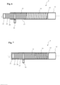
- the pole connector 13 is arranged between a Fig. 6 shown extended coupling position, via which the fence pole 9 can be connected to an adjacent fence pole 9, and one in Fig. 7 shown release position, in which the pole connector 13 is fully inserted into the fence tube 12, along or parallel to a longitudinal axis L of the fence tube 12 or the fence pole 9, displaceably guided in the fence tube 12.
- the pole connector 13 is pretensioned by a spring element 14 arranged in the fence tube 12 in the coupling position forming the basic position.
- the spring element 14 rests with one side on the inner end of the pole connector 13 lying in the fence tube 12 and with its other side on a limiting element 15 arranged in the fence tube 12.
- the limiting element 15 of the shown embodiment is specifically, as also in Fig. 4 is sketched, formed by a boundary pin inserted through the side wall of the fence tube 12.
- the rod connector 13 Via an actuating element 16 connected to the rod connector 13, the rod connector 13 can be moved from the Fig. 6 shown coupling position against the action of the spring element 14 into the Fig. 7
- the actuating element 16 of the exemplary embodiment shown is designed as an actuating pin inserted into a receptacle of the rod connector 13, wherein the actuating pin is guided outwards through a guide slot 17 of the fence tube 12 extending along the longitudinal axis L of the fence rod 9.
- the actuating element 16 resting against the longitudinal ends of the guide slot 17, the displacement path of the rod connector 13 is limited.
- the positions in which the actuating element 16 rests against the longitudinal ends of the guide slot 17 represent the coupling position and the release position, respectively, in the exemplary embodiment shown.
- the fence tube 12 has Fig. 4 and Fig. 5 shown right end a connecting section 18.
- the connecting section 18 has a reduced diameter compared to the rest of the fence tube 12.
- An engagement section 19 of the rod connector 13, which protrudes outwards in the coupling position, can be introduced into the connecting section 18.
- the engagement section 19 has a reduced diameter compared to the rest of the rod connector 13, forming a shoulder 20, wherein the outer diameter of the engagement region 19 substantially corresponds to the inner diameter of the connecting section 18.
- the connecting section 18 and the engagement region 19 of the rod connector 13 further have receiving openings 21, 24, into which, as described below with reference to Fig. 10 described in more detail, a securing element 22 can be inserted to secure the connection of adjacent fence poles 9.
- FIG. 8 The connection of two adjacent fence poles 9, 9', specifically the connection of the pole connector 13 of a first fence pole 9 with a connecting section 18' of a second fence pole 9', is outlined.
- the rod connector 13 of the first fence rod 9 is first moved into the release position via the actuating element 16, and the connecting section 18' of the second fence rod 9' and the end of the first fence rod 9 having the rod connector 13 are positioned adjacent to one another.
- the rod connector 13, as shown in Fig. 9 shown then moved into the coupling position, whereby the engagement area 19 of the rod connector 13 is engaged in the connecting section 18 ⁇ of the Fig.
Landscapes
- Engineering & Computer Science (AREA)
- General Engineering & Computer Science (AREA)
- Mechanical Engineering (AREA)
- Architecture (AREA)
- Civil Engineering (AREA)
- Structural Engineering (AREA)
- Refuge Islands, Traffic Blockers, Or Guard Fence (AREA)
Abstract
Zaunstange (9) für eine aus mehreren solcher Zaunstangen (9) gebildete Zaunstrebe (7) eines Gleisschutzzauns, wobei die Zaunstange (9) ein Zaunrohr (12) umfasst. Die Aufgabe, eine Zaunstange (9) für eine aus mehreren Zaunstangen (9) gebildete Zaunstrebe (7) eines Gleisschutzzauns (1) bereitzustellen, die ein einfaches Zusammenbauen und Lösen der Zaunstangen (9), insbesondere auch von mittig verbauten Zaunstangen (9), ermöglicht, löst die Anmeldung durch einen Stangenverbinder (13), der zwischen einer ausgefahrenen Kupplungsstellung zur Verbindung mit einer benachbarten Zaunstange (9) und einer in das Zaunrohr (12) eingefahrenen Lösestellung zum Lösen benachbarter Zaunstangen (9) einer Zaunstrebe (7) verschiebbar an einem ersten Ende des Zaunrohrs (12) angeordnet ist. Weiter ist eine aus mehreren Zaunstangen (9) gebildete Zaunstrebe (9) sowie ein zumindest eine Zaunstrebe (7) aufweisendes Gleisschutzzaunsystem (1) Gegenstand der Anmeldung.Fence post (9) for a fence strut (7) of a railway safety fence formed from a plurality of such fence posts (9), wherein the fence post (9) comprises a fence tube (12). The object of providing a fence post (9) for a fence strut (7) of a railway safety fence (1) formed from a plurality of fence posts (9), which enables easy assembly and release of the fence posts (9), in particular also of centrally installed fence posts (9), is achieved by the application by means of a post connector (13) which is arranged at a first end of the fence tube (12) and can be displaced between an extended coupling position for connection to an adjacent fence post (9) and a release position retracted into the fence tube (12) for releasing adjacent fence posts (9) of a fence strut (7). Furthermore, a fence strut (9) formed from several fence poles (9) and a track protection fence system (1) having at least one fence strut (7) are the subject of the application.
Description
Die Erfindung betrifft eine Zaunstange für eine aus mehreren solcher Zaunstangen gebildete Zaunstrebe eines Gleisschutzzauns nach dem Oberbegriff des Anspruchs 1, eine Zaunstrebe für einen Gleisschutzzaun nach Anspruch 13 und ein Gleisschutzzaunsystem nach Anspruch 15.The invention relates to a fence post for a fence strut of a track protection fence formed from a plurality of such fence posts according to the preamble of
Zur Absicherung von (temporären) Gleisbaustellen werden im Eisenbahnverkehr Gleisschutzzäune bzw. Gleiskörperschutzzäune eingesetzt, durch die ein ungewolltes Eindringen in einen Gleisbereich, beispielsweise ein Eindringen in den Bereich eines weiterhin befahrenen Gleises, verhindert werden soll.To secure (temporary) track construction sites, track protection fences or track bed protection fences are used in railway traffic to prevent unwanted intrusion into a track area, for example, an intrusion into the area of a track that is still in use.
Aus
Zum Verbinden der Zaunstangen von derartigen aus dem Stand der Technik bekannten durchgängigen Zaunstreben werden die Holme bzw. Zaunstangen üblicherweise der Reihe nach durch Einstecken eines Holmverbinders in den vorangehenden Holm und Aufstecken des nachfolgenden Holms auf den Holmverbinder miteinander verbunden. Entsprechend hierzu erfolgt üblicherweise ein Trennen der Holme schrittweise. Ein Verbinden und Lösen mittig innerhalb einer Zaunstrebe angeordneter Holme, beispielsweise um an einer Stelle des Gleiszauns kurzzeitig einen Zugang zu einem sicherheitskritischen Bereich zu schaffen, ist dabei problematisch und aufwendig. Dies gilt insbesondere, da benachbarte Holme einem Verschieben der zu trennenden Holme in axialer Richtung, d.h. entlang der Längsachse der Zaunstrebe, entgegenstehen.To connect the fence posts of such continuous fence struts known from the prior art, the stiles or fence posts are usually connected one after the other by inserting a stile connector into the preceding stile and attaching the subsequent stile onto the stile connector. Accordingly, the stiles are usually separated step by step. Connecting and disconnecting stiles arranged centrally within a fence strut, for example, to temporarily create access to a safety-critical area at one point on the rail fence, is problematic and complex. This is especially true since adjacent stiles are subject to a Displacement of the beams to be separated in the axial direction, i.e. along the longitudinal axis of the fence strut.
Ausgehend hiervon besteht die Aufgabe, eine Zaunstange für eine aus mehreren solcher Zaunstangen gebildete Zaunstrebe eines Gleisschutzzauns bereitzustellen, die ein einfaches Zusammenbauen und Lösen der Zaunstangen, insbesondere auch von mittig verbauten Zaunstangen, ermöglicht. Weiter soll eine aus mehreren Zaunstangen gebildete Zaunstrebe sowie ein zumindest eine Zaunstrebe aufweisendes Gleisschutzzaunsystem bereitgestellt werden.Based on this, the object is to provide a fence post for a fence strut of a railway protection fence formed from several such fence posts, which allows for easy assembly and disassembly of the fence posts, especially of centrally installed fence posts. Furthermore, a fence strut formed from several fence posts and a railway protection fence system comprising at least one fence strut are to be provided.
Gelöst wird diese Aufgabe mit einer Zaunstange nach Anspruch 1, einer Zaunstrebe nach Anspruch 13 sowie einem Gleisschutzzaunsystem nach Anspruch 15. Vorteilhafte Ausgestaltungen und zweckmäßige Weiterbildungen der Erfindung sind den Unteransprüchen entnehmbar.This object is achieved with a fence post according to
Die erfindungsgemäße Zaunstange für eine aus mehreren solcher Zaunstangen gebildete Zaunstrebe eines Gleisschutzzauns umfasst ein Zaunrohr (bzw. Zaunstangenrohr) sowie einen Stangenverbinder, wobei der Stangenverbinder zwischen einer ausgefahrenen Kupplungsstellung zur Verbindung mit einer benachbarten Zaunstange und einer in das Zaunrohr eingefahrenen Lösestellung zum Lösen benachbarter Zaunstangen einer Zaunstrebe verschiebbar an einem ersten Ende des Zaunrohrs angeordnet ist. Bei den (länglich ausgebildeten) Zaunrohren handelt es sich vorzugsweise um Rohre mit im Wesentlichen rundem oder rechteckigen, insbesondere quadratischem, Querschnitt. Der Stangenverbinder ist dabei innenliegend an dem ersten Ende des Zaunrohrs geführt. Das Verschieben des Stangenverbinders erfolgt dabei axial, d.h. parallel zur Längsachse des Zaunrohrs bzw. der Zaunstange. Zum Verbinden mit einer benachbarten Zaunstange wird der Stangenverbinder in der Kupplungsstellung in ein zur Aufnahme des Stangenverbinders geeignet ausgestaltetes Ende der benachbarten Zaunstange eingebracht. Durch die erfindungsgemäße Ausgestaltung ist ein Verbinden und Lösen der Zaunstangen ohne axiale Verschiebung der zu verbindenden bzw. zu trennenden Zaunstangen möglich. Speziell wird zum Lösen zweier miteinander verbundener Zaunstangen der die Zaunstangen verbindende Stangenverbinder in die eingefahrene Lösestellung verschoben. Hierdurch können die Zaunstangen auseinandergebracht, insbesondere transversal zur Längsachse der Zaunstrebe gegeneinander verschoben, werden. Das Lösen dieser nun voneinander getrennten Zaunstangen von dem jeweils noch mit dem über das andere Ende der Zaunstange verbundenen Rest der Zaunstrebe, d.h. von einer mit dem jeweils anderen Ende der Zaunstangen über einen Stangenverbinder verbundenen weiteren Zaunstange, kann entweder analog zu dem oben beschriebenen Einfahren des Stangenverbinders in die Lösestellung erfolgen. Durch die bereits erfolgte Trennung der Zaunstangen ist ein Lösen der Zaunstangen von dem Rest der Zaunstrebe jedoch auch durch ein axiales Bewegen dieser Zaunstangen entlang der Längsachse der Zaunstrebe möglich. Das Verbinden von benachbarten Zaunstangen, speziell von innenliegend innerhalb einer zusammengebauten Zaunstrebe zu verbindenden Zaunstangen, kann durch entsprechendes Verschieben des Stangenverbinders von der Lösestellung in die Kupplungsstellung und Einbringen des Stangenverbinders in die benachbarte Zaunstange erfolgen. Durch die erfindungsgemäße Ausgestaltung ist ein Lösen und Verbinden benachbarter Zaunstangen, insbesondere auch innenliegend in einer Zaunstrebe angeordneter Zaunstangen, auf einfache und zügige Weise möglich.The fence post according to the invention for a fence strut of a railway track protection fence formed from several such fence posts comprises a fence tube (or fence post tube) and a post connector, wherein the post connector is arranged at a first end of the fence tube so as to be displaceable between an extended coupling position for connection to an adjacent fence post and a release position retracted into the fence tube for releasing adjacent fence posts of a fence strut. The (elongated) fence tubes are preferably tubes with a substantially round or rectangular, in particular square, cross-section. The post connector is guided internally at the first end of the fence tube. The post connector is moved axially, i.e. parallel to the longitudinal axis of the fence tube or fence post. For connection to an adjacent fence post, the post connector is inserted in the coupling position into an end of the adjacent fence post designed to receive the post connector. The inventive design allows the fence poles to be connected and released without axial displacement of the fence poles to be connected or separated. Specifically, to release two connected fence poles, the pole connector connecting the fence poles is moved into the retracted release position. This allows the fence poles to be separated, in particular, moved against each other transversely to the longitudinal axis of the fence brace. The release of these now separated fence poles from the the other end of the fence post connected to the remainder of the fence strut, i.e. from another fence post connected to the other end of the fence posts via a post connector, can be carried out either analogously to the above-described insertion of the post connector into the release position. Because the fence posts have already been separated, the fence posts can also be released from the remainder of the fence strut by axially moving these fence posts along the longitudinal axis of the fence strut. The connection of adjacent fence posts, in particular fence posts to be connected inside an assembled fence strut, can be carried out by appropriately moving the post connector from the release position into the coupling position and inserting the post connector into the adjacent fence post. The design according to the invention makes it possible to release and connect adjacent fence posts, in particular fence posts arranged inside a fence strut, in a simple and rapid manner.
In einer vorteilhaften Ausgestaltung weist das Zaunrohr an einem zweiten Ende einen Verbindungsabschnitt, insbesondere einen gegenüber dem Rest des Zaunrohrs verjüngten Verbindungsabschnitt, d.h. in seiner Abmessung bzw. seinem Durchmesser reduzierten Verbindungsabschnitt, oder alternativ hierzu einen verbreiterten Verbindungsabschnitt, zur Verbindung mit dem Stangenverbinder einer benachbarten gleichartigen Zaunstange auf. Bevorzugt ist der Verbindungsabschnitt dabei zum Einbringen des Stangenverbinders einer benachbarten Zaunstange, insbesondere zur formschlüssigen Aufnahme des Stangenverbinders, ausgebildet. Durch die Ausgestaltung der Zaunstange mit dem Stangenverbinder an dem ersten Ende und dem Verbindungsabschnitt an dem zweiten Ende des Zaunrohrs können mehrere dieser Zaunstangen zur Bildung einer Zaunstrebe miteinander verbunden werden. Vorzugsweise weisen der Stangenverbinder und der Verbindungsabschnitt dabei jeweils zumindest eine Aufnahmeöffnung auf, insbesondere eine durch den Stangenverbinder bzw. den Verbindungsabschnitt durchgehende Aufnahmeöffnung. Bei einer Verbindung zweier gleichartiger Zaunstangen, d.h. bei einem Einbringen des Stangenverbinders einer ersten Zaunstange in den Verbindungsabschnitt einer zweiten Zaunstange, sind diese Aufnahmeöffnungen vorzugsweise konzentrisch bzw. übereinanderliegend angeordnet. Zur sicheren Verbindung des Stangenverbinders und des Verbindungsabschnitts ist in die übereinanderliegend angeordneten Aufnahmeöffnungen ein Sicherungselement, beispielsweise ein Sicherungsstift, einbringbar. Hierdurch wird eine sichere Verbindung benachbarter Zaunstangen gewährleistet, wobei insbesondere eine ungewollte laterale Bewegung bzw. ein Auseinanderbewegen und ein hierdurch bewirktes Lösen benachbarter Zaunstangen zuverlässig verhindert wird. In einer besonders vorteilhaften Ausgestaltung weist der Stangenverbinder einen Eingriffsabschnitt auf, der vorzugsweise eine gegenüber dem restlichen Stangenverbinder verringerte Abmessung, speziell einen geringeren (Außen-) Durchmesser, aufweist. In der Kupplungsstellung greift der Eingriffsabschnitt dabei in den Verbindungsabschnitt einer benachbarten Zaunstange ein. Der Übergang des Eingriffsabschnitts zu dem restlichen Stangenverbinder wird vorzugsweise durch einen Absatz gebildet. Bei einer Verbindung zweier Zaunstangen steht die Außenkante des Verbindungsabschnitts hierbei vorzugsweise an dem Absatz an. Über das Anstehen des Absatzes an der Außenkante wird die Eindringtiefe des Stangenverbinders begrenzt. Weiter kann durch die genannte Ausgestaltung auch sichergestellt werden, dass Aufnahmeöffnungen am Eingriffsbereich des Stangenverbinders und Aufnahmeöffnungen des Verbindungsabschnitts zum Einbringen eines Sicherungselements in entsprechend übereinander angeordneter Position zum Liegen kommen.In an advantageous embodiment, the fence tube has a connecting section at a second end, in particular a connecting section that is tapered compared to the rest of the fence tube, i.e. a connecting section with a reduced size or diameter, or alternatively a widened connecting section, for connection to the pole connector of an adjacent, similar fence pole. The connecting section is preferably designed for inserting the pole connector of an adjacent fence pole, in particular for positively receiving the pole connector. By designing the fence pole with the pole connector at the first end and the connecting section at the second end of the fence tube, several of these fence poles can be connected to one another to form a fence strut. The pole connector and the connecting section preferably each have at least one receiving opening, in particular a receiving opening extending through the pole connector or the connecting section. When connecting two similar fence poles, i.e. when inserting the pole connector of a first fence pole into the connecting section of a second fence pole, these receiving openings are preferably arranged concentrically or one above the other. For a secure connection of the pole connector and the connecting section, a securing element, for example a securing pin, can be inserted into the receiving openings arranged one above the other. This ensures a secure connection of adjacent fence poles, in particular unwanted lateral movement or a moving apart and the resulting loosening of adjacent fence poles is reliably prevented. In a particularly advantageous embodiment, the pole connector has an engagement section which preferably has a smaller dimension than the rest of the pole connector, specifically a smaller (outer) diameter. In the coupling position, the engagement section engages in the connecting section of an adjacent fence pole. The transition from the engagement section to the rest of the pole connector is preferably formed by a shoulder. When two fence poles are connected, the outer edge of the connecting section preferably rests on the shoulder. The penetration depth of the pole connector is limited by the shoulder resting on the outer edge. Furthermore, the aforementioned embodiment can also ensure that receiving openings in the engagement area of the pole connector and receiving openings in the connecting section for introducing a securing element are arranged in a correspondingly superimposed position.
In einer weiteren vorteilhaften Ausgestaltung ist der Stangenverbinder in der Kupplungsstellung oder der Lösestellung federnd vorgespannt. Die federnde Vorspannung des Stangenverbinders in einer der genannten Positionen ist insbesondere für das Verbinden und/oder Lösen benachbarter Zaunstangen vorteilhaft. Vorzugsweise ist der Stangenverbinder in der die Grundstellung darstellenden Kupplungsstellung vorgespannt, so dass der Stangenverbinder bereits durch die federnde Vorspannung in der die Verbindung zweier benachbarter Zaunstangen bewirkenden Kopplungsstellung gehalten wird. In einer besonders vorteilhaften Ausgestaltung ist in dem Zaunrohr ein Begrenzungselement und zwischen dem Begrenzungselement und dem Stangenverbinder ein Federelement angeordnet. Das Begrenzungselement kann dabei insbesondere ein in die Zaunstange eingebrachter Begrenzungsstift sein. Durch die genannte Ausgestaltung ist eine besonders einfach herzustellende und robuste Ausgestaltung eines federnd in der Zaunstange vorgespannten Stangenverbinders gegeben.In a further advantageous embodiment, the pole connector is resiliently preloaded in the coupling position or the release position. The resilient preload of the pole connector in one of the aforementioned positions is particularly advantageous for connecting and/or releasing adjacent fence poles. Preferably, the pole connector is preloaded in the coupling position, which represents the basic position, so that the pole connector is already held by the resilient preload in the coupling position, which connects two adjacent fence poles. In a particularly advantageous embodiment, a limiting element is arranged in the fence tube, and a spring element is arranged between the limiting element and the pole connector. The limiting element can, in particular, be a limiting pin inserted into the fence pole. This embodiment provides a particularly simple-to-manufacture and robust design for a pole connector that is resiliently preloaded in the fence pole.
Vorzugsweise ist der Stangenverbinder in der Lösestellung vollständig oder zumindest nahezu vollständig in das Zaunrohr eingebracht. Das Lösen bzw. Verbinden zweier Zaunstangen wird hierbei durch den in der Lösestellung angeordneten Stangenverbinder nicht behindert.Preferably, the pole connector is fully or at least almost fully inserted into the fence tube in the release position. The release position of the pole connector does not impede the connection or disconnection of two fence poles.
In einer bevorzugten Ausgestaltung ist ein mit dem Stangenverbinder verbundenes Betätigungselement zur insbesondere manuellen Verschiebung des Stangenverbinders von der Kupplungsstellung in die Lösestellung und/oder von der Lösestellung in die Kupplungsstellung vorgesehen. Das Verschieben des Stangenverbinders kann dabei vorzugsweise unmittelbar über das Betätigungselement erfolgen. Ein weiteres, insbesondere spezielles Werkzeug ist hierfür nicht erforderlich. Über das Betätigungselement ist ein einfaches Verbringen des Stangenverbinders von der Kupplungsstellung in die Lösestellung bzw. umgekehrt durch einen Benutzer möglich. Besonders bevorzugt ist das Betätigungselement dabei in einem Führungsschlitz des Zaunrohrs geführt. Das Betätigungselement ist dabei insbesondere von dem innenliegend in dem Zaunrohr verschiebbar angeordneten Stangenverbinder durch den Führungsschlitz hindurch nach außen geführt. Der Führungsschlitz ist dabei vorzugsweise als ein sich entlang der Längsachse des Zaunrohrs bzw. der Zaunstange erstreckendes Langloch ausgestaltet. Durch den Führungsschlitz, speziell ein Anliegen des Betätigungselements an den Enden des Führungsschlitzes, kann dabei der Verschiebeweg des Betätigungselements und somit ein Verschieben des Stangenverbinders begrenzt werden. Speziell kann dabei ein Verschieben des Stangenverbinders über die Kupplungsstellung und/oder die Lösestellung hinaus verhindert werden.In a preferred embodiment, an actuating element connected to the rod connector is provided for the manual displacement of the rod connector from the Coupling position into the release position and/or from the release position into the coupling position. The rod connector can preferably be moved directly via the actuating element. No further, in particular special, tool is required for this. The actuating element enables a user to easily move the rod connector from the coupling position to the release position and vice versa. The actuating element is particularly preferably guided in a guide slot in the fence tube. The actuating element is guided outwards, in particular from the rod connector arranged displaceably inside the fence tube, through the guide slot. The guide slot is preferably designed as an elongated hole extending along the longitudinal axis of the fence tube or fence rod. The guide slot, in particular by the actuating element bearing against the ends of the guide slot, can limit the displacement path of the actuating element and thus any displacement of the rod connector. In particular, displacement of the rod connector beyond the coupling position and/or the release position can be prevented.
Bei dem Stangenverbinder kann es sich beispielsweise um einen im Wesentlichen zylinderförmigen Vollkörper handeln. Um Ladungsverschleppung über große Strecken entlang des abgesperrten Bereiches bzw. entlang der Zaunstrebe zu verhindern, ist der Stangenverbinder vorzugsweise elektrisch isolierend ausgebildet, beispielsweise aus einem Kunststoff geformt.The pole connector can, for example, be a substantially cylindrical solid body. To prevent the spread of charge over long distances along the cordoned-off area or along the fence strut, the pole connector is preferably designed to be electrically insulating, for example, molded from a plastic.
Gegenstand der Erfindung ist weiter eine Zaunstrebe für einen Gleisschutzzaun umfassend mehrere oben beschriebene, insbesondere gleichartige, Zaunstangen, die miteinander verbindbar bzw. verbunden sind. Insbesondere sind zwei benachbarte Zaunstangen dabei über den Zaunstangenverbinder verbunden. Ein Zaunstangenverbinder einer ersten Zaunstange greift dabei insbesondere in den Verbindungsabschnitt einer zweiten Zaunstange ein. Vorzugsweise sind die miteinander verbundenen Zaunstangen durch ein in die Aufnahmeöffnung des Stangenverbinders der ersten Zaunstange und die Aufnahmeöffnung des Verbindungsabschnitts der zweiten Zaunstange einbringbares Sicherungselement gesichert.The invention further relates to a fence brace for a railway safety fence, comprising a plurality of fence poles described above, in particular of the same type, which are connectable or connected to one another. In particular, two adjacent fence poles are connected via the fence pole connector. A fence pole connector of a first fence pole engages in particular into the connecting section of a second fence pole. The interconnected fence poles are preferably secured by a securing element that can be inserted into the receiving opening of the pole connector of the first fence pole and the receiving opening of the connecting section of the second fence pole.
Zudem ist ein Gleisschutzzaunsystem umfassend eine oben beschriebene Zaunstrebe sowie ein an einer Schiene anbringbares Gleisschutzzaunhaltesystem mit zumindest einer Zaunhalterung, die mindestens eine, bevorzugt mehrere Aufhängungen aufweist, in die die Zaunstrebe einlegbar und sicherbar ist, Gegenstand der Erfindung. Die Aufhängungen weisen dabei vorzugsweise eine an die Außenkontur der Zaunstangen angepasste Stangenaufnahme auf, in die die Zaunstrebe, bzw. die zur Ausbildung der Zaunstrebe miteinander verbundenen Zaunstangen, von oben eingelegt und anschließend durch eine die Entnahme aus der Stangenaufnahme verhindernde, speziell eine die Öffnung der Stangenaufnahme begrenzende, Sicherungseinheit gesichert werden können. Vorzugsweise werden die Zaunstreben dabei klemmend in den Stangenaufnahmen fixiert. Durch die Klemmung der Zaunstangen der Zaunstrebe an den Zaunhalterungen und die Verbindung mehrerer Zaunstangen erfolgt eine Versteifung des Gleisschutzzauns bzw. des Gleisschutzzaunsystems. Die Versteifung verleiht dem Gleisschutzzaunsystem große Stabilität über deren Verlauf parallel zur Schiene hinweg.In addition, a rail protection fence system comprising a fence strut as described above and a rail protection fence support system that can be attached to a rail and has at least one fence support, which has at least one, preferably several suspensions, into which the fence strut can be inserted and secured, is the subject of the invention. The suspensions have Preferably, the fence post has a post holder adapted to the outer contour of the fence posts, into which the fence brace, or the fence posts connected to form the fence brace, can be inserted from above and then secured by a locking device that prevents removal from the post holder, specifically a locking device that limits the opening of the post holder. Preferably, the fence posts are clamped into the post holders. Clamping the fence posts of the fence brace to the fence brackets and connecting several fence posts stiffens the rail protection fence or rail protection fence system. This stiffening gives the rail protection fence system great stability along its run parallel to the rail.
Gegenstand der Offenbarung ist zudem eine Zaunstange für eine aus mehreren solcher Zaunstangen gebildete Zaunstrebe eines Gleisschutzzauns, wobei die Zaunstange einen Stangenverbinder, der zwischen einer ausgefahrenen Kupplungsstellung zur Verbindung mit einer benachbarten Zaunstange und einer in die Zaunstange eingefahrenen Lösestellung zum Lösen benachbarter Zaunstangen einer Zaunstrebe verschiebbar an einem ersten Ende der Zaunstange angeordnet ist. Der Stangenverbinder ist insbesondere parallel zu einer Längsachse des Stangenverbinders zwischen der Kupplungsstellung und der Lösestellung verschiebbar. Vorzugsweise weist die Zaunstange an einem zweiten Ende einen Verbindungsabschnitt, insbesondere einen Verbindungsabschnitt mit verringerter oder verbreiterter Abmessung, zur Verbindung mit dem Stangenverbinder einer benachbarten gleichartigen Zaunstange auf, wobei der Verbindungsabschnitt insbesondere zum Einbringen des Stangenverbinders einer benachbarten Zaunstange ausgebildet ist. Bezüglich der möglichen bevorzugten Ausgestaltungen, speziell auch betreffend die Aufnahmeöffnungen des Stangenverbinders sowie des Verbindungsabschnitts zur Einbringung eines Sicherungselements oder die Ausgestaltung des Stangenverbinders mit dem Eingriffsabschnitt oder dessen federnde Vorspannung in der Kupplungsstellung oder die Ausgestaltung des Stangenverbinders als elektrisch isolierender Stangenverbinder gelten für die hier genannte Zaunstange obige Ausführungen entsprechend. Weiter kann die genannte Zaunstange ein Begrenzungselement, insbesondere einen in die Zaunstange eingebrachten Begrenzungsstift, und ein zwischen dem Begrenzungselement und dem Stangenverbinder angeordnetes Federelement aufweisen. Vorzugsweise ist der Stangenverbinder der genannten Zaunstange in der Lösestellung vollständig in die Zaunstange eingebracht. In einer vorteilhaften Ausgestaltung weist die genannte Zaunstange einen oben beschriebenen Führungsschlitz zur Führung eines mit dem Stangenverbinder verbundenen Betätigungselements zur Verschiebung des Stangenverbinders auf. Diesbezüglich sowie auch im Übrigen gelten obige Ausführungen für die genannte Zaunstange in entsprechender Weise. Weiter ist eine Zaunstrebe mit mehreren derartigen miteinander verbindbaren bzw. verbundenen Zaunstangen sowie ein Gleisschutzzaunsystem umfassend eine derartige Zaunstrebe sowie das oben genannte Gleisschutzzaunhaltesystem Gegenstand der Offenbarung.The disclosure also relates to a fence post for a fence strut of a railway protection fence formed from a plurality of such fence posts, wherein the fence post has a pole connector which is arranged at a first end of the fence post and is displaceable between an extended coupling position for connection to an adjacent fence post and a release position retracted into the fence post for releasing adjacent fence posts of a fence strut. The pole connector is displaceable, in particular parallel to a longitudinal axis of the pole connector, between the coupling position and the release position. Preferably, the fence post has a connecting section at a second end, in particular a connecting section with a reduced or widened dimension, for connection to the pole connector of an adjacent, similar fence post, wherein the connecting section is designed, in particular, for introducing the pole connector of an adjacent fence post. With regard to the possible preferred embodiments, especially also concerning the receiving openings of the pole connector and the connecting section for introducing a securing element, or the design of the pole connector with the engagement section or its resilient pretension in the coupling position, or the design of the pole connector as an electrically insulating pole connector, the above statements apply accordingly to the fence pole mentioned here. Furthermore, the fence pole mentioned can have a limiting element, in particular a limiting pin introduced into the fence pole, and a spring element arranged between the limiting element and the pole connector. Preferably, the pole connector of the fence pole mentioned is completely inserted into the fence pole in the release position. In an advantageous embodiment, the fence pole mentioned has a guide slot described above for guiding an actuating element connected to the pole connector for displacing the pole connector. In this regard, and also in other respects, the above statements apply accordingly to the aforementioned fence post. Furthermore, a fence brace with several such interconnectable or connected fence posts, as well as a railroad safety fence system comprising such a fence brace and the aforementioned railroad safety fence support system, are the subject of the disclosure.
Diese und weitere Merkmale sowie Vorteile und Wirkungen der erfindungsgemäßen Zaunstange sowie der aus diesen gebildeten Zaunstrebe für ein Gleisschutzzaunsystem ergeben sich aus den nachfolgenden unter Bezugnahme auf die begleitenden Zeichnungen näher beschriebenen Ausführungsbeispielen. Die Zeichnungen zeigen:
- Fig. 1
- ein Gleisschutzzaunsystem umfassend einen aus mehreren Zaunstreben gebildeten Gleisschutzzaun sowie ein an einer Schiene angebrachtes Gleisschutzzaunhaltesystem;
- Fig. 2
- eine Seitenansicht eines Gleisschutzzaunhaltesystems aus
Fig. 1 ; - Fig. 3
- eine Detailansicht einer Aufhängung einer Zaunhalterung des Gleisschutzzaunsystems aus
Fig. 2 ; - Fig. 4
- ein Ausschnitt einer Zaunstange der Zaunstreben des Gleisschutzzauns aus
Fig. 1 in einer Seitenansicht; - Fig. 5
- ein Ausschnitt einer Zaunstange der Zaunstreben des Gleisschutzzauns aus
Fig. 1 in einer geschnittenen Seitenansicht; - Fig. 6
- eine vergrößerte Darstellung der Zaunstange aus
Fig. 5 mit in der Kupplungsstellung angeordnetem Stangenverbinder; - Fig. 7
- eine vergrößerte Darstellung der Zaunstange aus
Fig. 5 mit in der Lösestellung angeordnetem Stangenverbinder; - Fig. 8
- eine geschnittene Seitenansicht zweier benachbarter Zaunstangen einer Zaunstrebe in nicht verbundenem, gelöstem Zustand;
- Fig. 9
- eine geschnittene Seitenansicht zweier benachbarter Zaunstangen einer Zaunstrebe in verbundenem, nicht gesichertem Zustand;
- Fig. 10
- eine geschnittene Seitenansicht zweier benachbarter Zaunstangen einer Zaunstrebe in verbundenem, gesichertem Zustand.
- Fig. 1
- a track protection fence system comprising a track protection fence formed from a plurality of fence struts and a track protection fence holding system attached to a rail;
- Fig. 2
- a side view of a rail protection fence holding system from
Fig. 1 ; - Fig. 3
- a detailed view of a suspension of a fence bracket of the railway protection fence system from
Fig. 2 ; - Fig. 4
- a section of a fence post of the rail protection fence from
Fig. 1 in a side view; - Fig. 5
- a section of a fence post of the rail protection fence from
Fig. 1 in a sectioned side view; - Fig. 6
- an enlarged view of the fence post from
Fig. 5 with rod connector arranged in the coupling position; - Fig. 7
- an enlarged view of the fence post from
Fig. 5 with rod connector arranged in the release position; - Fig. 8
- a sectional side view of two adjacent fence posts of a fence brace in an unconnected, detached state;
- Fig. 9
- a sectional side view of two adjacent fence posts of a fence brace in a connected, unsecured state;
- Fig. 10
- a sectional side view of two adjacent fence posts of a fence brace in a connected, secured state.
Der in
Die beiden Endbereiche einer Zaunstange 9 der Zaunstrebe 7 aus
An dem in
Über ein mit dem Stangenverbinder 13 in Verbindung stehendes Betätigungselement 16 kann der Stangenverbinder 13 von der in
Zum unten in Bezug auf
In
Der Vollständigkeit halber wird darauf hingewiesen, dass die vorliegende Erfindung nicht auf das vorliegend gezeigte Ausführungsbeispiel beschränkt ist. Beispielsweise sind auch Zaunstreben 7 bzw. Zaunrohre 12 und Stangenverbinder 13 mit einem quadratischen Querschnitt denkbar. Weiter sind auch andere Ausgestaltungen der horizontalen Strebenanordnung 5 sowie der Zaunhalterung 6 denkbar, wie beispielsweise Streben, die eine runde oder eine anderen Querschnittsform aufweisen.For the sake of completeness, it should be noted that the present invention is not limited to the embodiment shown here. For example, fence struts 7 or
- 11
- GleisschutzzaunsystemRailway protection fence system
- 22
- GleisschutzzaunhaltesystemRail protection fence holding system
- 33
- Schienerail
- 44
- SchienenfußhalterungRail foot bracket
- 55
- Horizontale StrebenanordnungHorizontal strut arrangement
- 66
- ZaunhalterungFence bracket
- 77
- ZaunstrebeFence brace
- 88
- Aufhängungsuspension
- 99
- Zaunstangefence post
- 1010
- StangenaufnahmeRod holder
- 1111
- Klemmsteinclamping stone
- 1212
- ZaunrohrFence pipe
- 1313
- StangenverbinderRod connectors
- 1414
- Federelementspring element
- 1515
- BegrenzungselementBoundary element
- 1616
- BetätigungselementActuating element
- 1717
- FührungsschlitzGuide slot
- 1818
- Verbindungsabschnittconnecting section
- 1919
- EingriffsabschnittIntervention section
- 2020
- AbsatzParagraph
- 2121
- Aufnahmeöffnung des StangenverbindersReceiving opening of the rod connector
- 2222
- Sicherungselementsecuring element
- 2323
- Flügelmutterwing nut
- 2424
- Aufnahmeöffnung des VerbindungsabschnittsReceiving opening of the connecting section
- LL
- LängsachseLongitudinal axis
Claims (15)
Applications Claiming Priority (1)
| Application Number | Priority Date | Filing Date | Title |
|---|---|---|---|
| DE102023128112.7A DE102023128112A1 (en) | 2023-10-13 | 2023-10-13 | Fence post for a fence strut of a railway protection fence formed from several such fence posts, fence strut for a railway protection fence and railway protection fence system |
Publications (1)
| Publication Number | Publication Date |
|---|---|
| EP4538457A1 true EP4538457A1 (en) | 2025-04-16 |
Family
ID=92966679
Family Applications (1)
| Application Number | Title | Priority Date | Filing Date |
|---|---|---|---|
| EP24203963.4A Pending EP4538457A1 (en) | 2023-10-13 | 2024-10-01 | Fence bar for a fence strut of a track fence formed of a plurality of such fence bars, fence strut for a track fence and track fence system |
Country Status (2)
| Country | Link |
|---|---|
| EP (1) | EP4538457A1 (en) |
| DE (1) | DE102023128112A1 (en) |
Citations (3)
| Publication number | Priority date | Publication date | Assignee | Title |
|---|---|---|---|---|
| DE102005022316A1 (en) * | 2004-09-16 | 2006-03-23 | Hünnebeck Group GmbH | Post for inserting into a connecting piece as an extension column at construction sites to provide safety against falling which has bolting device and control element |
| EP3421024B1 (en) * | 2017-06-26 | 2020-01-08 | Winncare France | Telescopic post of bed barrier and hospital bed comprising such a barrier |
| EP3936663A1 (en) | 2020-07-08 | 2022-01-12 | ARC Allround Cleaning Rheinfelden AG | Track protection fence system |
-
2023
- 2023-10-13 DE DE102023128112.7A patent/DE102023128112A1/en active Pending
-
2024
- 2024-10-01 EP EP24203963.4A patent/EP4538457A1/en active Pending
Patent Citations (3)
| Publication number | Priority date | Publication date | Assignee | Title |
|---|---|---|---|---|
| DE102005022316A1 (en) * | 2004-09-16 | 2006-03-23 | Hünnebeck Group GmbH | Post for inserting into a connecting piece as an extension column at construction sites to provide safety against falling which has bolting device and control element |
| EP3421024B1 (en) * | 2017-06-26 | 2020-01-08 | Winncare France | Telescopic post of bed barrier and hospital bed comprising such a barrier |
| EP3936663A1 (en) | 2020-07-08 | 2022-01-12 | ARC Allround Cleaning Rheinfelden AG | Track protection fence system |
Also Published As
| Publication number | Publication date |
|---|---|
| DE102023128112A1 (en) | 2025-04-17 |
Similar Documents
| Publication | Publication Date | Title |
|---|---|---|
| EP2443352B1 (en) | Profile bar connection system | |
| EP0297033A2 (en) | Fixing element for a rod | |
| DE102020134286A1 (en) | connecting sleeve | |
| EP3445935B1 (en) | Sliding door assembly | |
| DE202017107404U1 (en) | Node connector for profile systems or the like | |
| DE202014002813U1 (en) | Temporary wall support | |
| WO2018024447A1 (en) | Connector | |
| DE10315690B4 (en) | Fastening device for a hitch on a longitudinal member of a motor vehicle | |
| DE102014110192A1 (en) | Fastener for a mounting rail | |
| DE102009013981B4 (en) | spacer | |
| DE4239805C2 (en) | Bracing system | |
| EP0004374A1 (en) | Device for joining two profiled bars | |
| DE10225403B4 (en) | studding | |
| DE10112035B4 (en) | Safety fence | |
| EP4538457A1 (en) | Fence bar for a fence strut of a track fence formed of a plurality of such fence bars, fence strut for a track fence and track fence system | |
| EP1853827B1 (en) | Profile connector | |
| DE102019130855A1 (en) | Connection system and shelving system | |
| DE3208576A1 (en) | Pipe connection | |
| DE202023105928U1 (en) | Fence post for a fence strut of a railway protection fence formed from several such fence posts, fence strut for a railway protection fence and railway protection fence system | |
| EP1111141A2 (en) | Installation fitting with releasable socket coupling connection | |
| DE19841314A1 (en) | Tube connector for connecting tubes used e.g. in stage construction connects the tube insides and has a lock on the top and bottom | |
| EP1760840B1 (en) | Electrical connector and seat with such an connector | |
| DE602004004485T2 (en) | fence posts | |
| DE202007015012U1 (en) | Protective wall arrangement for limiting and safeguarding roadways, in particular in construction site areas | |
| DE10051323B4 (en) | tow bar |
Legal Events
| Date | Code | Title | Description |
|---|---|---|---|
| PUAI | Public reference made under article 153(3) epc to a published international application that has entered the european phase |
Free format text: ORIGINAL CODE: 0009012 |
|
| STAA | Information on the status of an ep patent application or granted ep patent |
Free format text: STATUS: THE APPLICATION HAS BEEN PUBLISHED |
|
| AK | Designated contracting states |
Kind code of ref document: A1 Designated state(s): AL AT BE BG CH CY CZ DE DK EE ES FI FR GB GR HR HU IE IS IT LI LT LU LV MC ME MK MT NL NO PL PT RO RS SE SI SK SM TR |
|
| STAA | Information on the status of an ep patent application or granted ep patent |
Free format text: STATUS: REQUEST FOR EXAMINATION WAS MADE |
|
| 17P | Request for examination filed |
Effective date: 20251016 |