EP4538084A2 - Antriebsmodul eines elektrischen oder hybridfahrzeugs - Google Patents
Antriebsmodul eines elektrischen oder hybridfahrzeugs Download PDFInfo
- Publication number
- EP4538084A2 EP4538084A2 EP25158095.7A EP25158095A EP4538084A2 EP 4538084 A2 EP4538084 A2 EP 4538084A2 EP 25158095 A EP25158095 A EP 25158095A EP 4538084 A2 EP4538084 A2 EP 4538084A2
- Authority
- EP
- European Patent Office
- Prior art keywords
- module
- housing part
- voltage converter
- cooling circuit
- electric propulsion
- Prior art date
- Legal status (The legal status is an assumption and is not a legal conclusion. Google has not performed a legal analysis and makes no representation as to the accuracy of the status listed.)
- Pending
Links
Images

Classifications
-
- B—PERFORMING OPERATIONS; TRANSPORTING
- B60—VEHICLES IN GENERAL
- B60L—PROPULSION OF ELECTRICALLY-PROPELLED VEHICLES; SUPPLYING ELECTRIC POWER FOR AUXILIARY EQUIPMENT OF ELECTRICALLY-PROPELLED VEHICLES; ELECTRODYNAMIC BRAKE SYSTEMS FOR VEHICLES IN GENERAL; MAGNETIC SUSPENSION OR LEVITATION FOR VEHICLES; MONITORING OPERATING VARIABLES OF ELECTRICALLY-PROPELLED VEHICLES; ELECTRIC SAFETY DEVICES FOR ELECTRICALLY-PROPELLED VEHICLES
- B60L50/00—Electric propulsion with power supplied within the vehicle
- B60L50/50—Electric propulsion with power supplied within the vehicle using propulsion power supplied by batteries or fuel cells
- B60L50/60—Electric propulsion with power supplied within the vehicle using propulsion power supplied by batteries or fuel cells using power supplied by batteries
-
- B—PERFORMING OPERATIONS; TRANSPORTING
- B60—VEHICLES IN GENERAL
- B60K—ARRANGEMENT OR MOUNTING OF PROPULSION UNITS OR OF TRANSMISSIONS IN VEHICLES; ARRANGEMENT OR MOUNTING OF PLURAL DIVERSE PRIME-MOVERS IN VEHICLES; AUXILIARY DRIVES FOR VEHICLES; INSTRUMENTATION OR DASHBOARDS FOR VEHICLES; ARRANGEMENTS IN CONNECTION WITH COOLING, AIR INTAKE, GAS EXHAUST OR FUEL SUPPLY OF PROPULSION UNITS IN VEHICLES
- B60K6/00—Arrangement or mounting of plural diverse prime-movers for mutual or common propulsion, e.g. hybrid propulsion systems comprising electric motors and internal combustion engines
- B60K6/20—Arrangement or mounting of plural diverse prime-movers for mutual or common propulsion, e.g. hybrid propulsion systems comprising electric motors and internal combustion engines the prime-movers consisting of electric motors and internal combustion engines, e.g. HEVs
- B60K6/22—Arrangement or mounting of plural diverse prime-movers for mutual or common propulsion, e.g. hybrid propulsion systems comprising electric motors and internal combustion engines the prime-movers consisting of electric motors and internal combustion engines, e.g. HEVs characterised by apparatus, components or means specially adapted for HEVs
- B60K6/40—Arrangement or mounting of plural diverse prime-movers for mutual or common propulsion, e.g. hybrid propulsion systems comprising electric motors and internal combustion engines the prime-movers consisting of electric motors and internal combustion engines, e.g. HEVs characterised by apparatus, components or means specially adapted for HEVs characterised by the assembly or relative disposition of components
-
- B—PERFORMING OPERATIONS; TRANSPORTING
- B60—VEHICLES IN GENERAL
- B60K—ARRANGEMENT OR MOUNTING OF PROPULSION UNITS OR OF TRANSMISSIONS IN VEHICLES; ARRANGEMENT OR MOUNTING OF PLURAL DIVERSE PRIME-MOVERS IN VEHICLES; AUXILIARY DRIVES FOR VEHICLES; INSTRUMENTATION OR DASHBOARDS FOR VEHICLES; ARRANGEMENTS IN CONNECTION WITH COOLING, AIR INTAKE, GAS EXHAUST OR FUEL SUPPLY OF PROPULSION UNITS IN VEHICLES
- B60K6/00—Arrangement or mounting of plural diverse prime-movers for mutual or common propulsion, e.g. hybrid propulsion systems comprising electric motors and internal combustion engines
- B60K6/20—Arrangement or mounting of plural diverse prime-movers for mutual or common propulsion, e.g. hybrid propulsion systems comprising electric motors and internal combustion engines the prime-movers consisting of electric motors and internal combustion engines, e.g. HEVs
- B60K6/22—Arrangement or mounting of plural diverse prime-movers for mutual or common propulsion, e.g. hybrid propulsion systems comprising electric motors and internal combustion engines the prime-movers consisting of electric motors and internal combustion engines, e.g. HEVs characterised by apparatus, components or means specially adapted for HEVs
- B60K6/40—Arrangement or mounting of plural diverse prime-movers for mutual or common propulsion, e.g. hybrid propulsion systems comprising electric motors and internal combustion engines the prime-movers consisting of electric motors and internal combustion engines, e.g. HEVs characterised by apparatus, components or means specially adapted for HEVs characterised by the assembly or relative disposition of components
- B60K6/405—Housings
-
- B—PERFORMING OPERATIONS; TRANSPORTING
- B60—VEHICLES IN GENERAL
- B60L—PROPULSION OF ELECTRICALLY-PROPELLED VEHICLES; SUPPLYING ELECTRIC POWER FOR AUXILIARY EQUIPMENT OF ELECTRICALLY-PROPELLED VEHICLES; ELECTRODYNAMIC BRAKE SYSTEMS FOR VEHICLES IN GENERAL; MAGNETIC SUSPENSION OR LEVITATION FOR VEHICLES; MONITORING OPERATING VARIABLES OF ELECTRICALLY-PROPELLED VEHICLES; ELECTRIC SAFETY DEVICES FOR ELECTRICALLY-PROPELLED VEHICLES
- B60L15/00—Methods, circuits, or devices for controlling the traction-motor speed of electrically-propelled vehicles
- B60L15/007—Physical arrangements or structures of drive train converters specially adapted for the propulsion motors of electric vehicles
-
- B—PERFORMING OPERATIONS; TRANSPORTING
- B60—VEHICLES IN GENERAL
- B60L—PROPULSION OF ELECTRICALLY-PROPELLED VEHICLES; SUPPLYING ELECTRIC POWER FOR AUXILIARY EQUIPMENT OF ELECTRICALLY-PROPELLED VEHICLES; ELECTRODYNAMIC BRAKE SYSTEMS FOR VEHICLES IN GENERAL; MAGNETIC SUSPENSION OR LEVITATION FOR VEHICLES; MONITORING OPERATING VARIABLES OF ELECTRICALLY-PROPELLED VEHICLES; ELECTRIC SAFETY DEVICES FOR ELECTRICALLY-PROPELLED VEHICLES
- B60L2240/00—Control parameters of input or output; Target parameters
- B60L2240/40—Drive Train control parameters
- B60L2240/42—Drive Train control parameters related to electric machines
- B60L2240/425—Temperature
-
- B—PERFORMING OPERATIONS; TRANSPORTING
- B60—VEHICLES IN GENERAL
- B60L—PROPULSION OF ELECTRICALLY-PROPELLED VEHICLES; SUPPLYING ELECTRIC POWER FOR AUXILIARY EQUIPMENT OF ELECTRICALLY-PROPELLED VEHICLES; ELECTRODYNAMIC BRAKE SYSTEMS FOR VEHICLES IN GENERAL; MAGNETIC SUSPENSION OR LEVITATION FOR VEHICLES; MONITORING OPERATING VARIABLES OF ELECTRICALLY-PROPELLED VEHICLES; ELECTRIC SAFETY DEVICES FOR ELECTRICALLY-PROPELLED VEHICLES
- B60L2240/00—Control parameters of input or output; Target parameters
- B60L2240/40—Drive Train control parameters
- B60L2240/48—Drive Train control parameters related to transmissions
- B60L2240/485—Temperature
-
- B—PERFORMING OPERATIONS; TRANSPORTING
- B60—VEHICLES IN GENERAL
- B60L—PROPULSION OF ELECTRICALLY-PROPELLED VEHICLES; SUPPLYING ELECTRIC POWER FOR AUXILIARY EQUIPMENT OF ELECTRICALLY-PROPELLED VEHICLES; ELECTRODYNAMIC BRAKE SYSTEMS FOR VEHICLES IN GENERAL; MAGNETIC SUSPENSION OR LEVITATION FOR VEHICLES; MONITORING OPERATING VARIABLES OF ELECTRICALLY-PROPELLED VEHICLES; ELECTRIC SAFETY DEVICES FOR ELECTRICALLY-PROPELLED VEHICLES
- B60L2240/00—Control parameters of input or output; Target parameters
- B60L2240/40—Drive Train control parameters
- B60L2240/52—Drive Train control parameters related to converters
- B60L2240/525—Temperature of converter or components thereof
Definitions
- the present invention relates to a propulsion module for an electric or hybrid vehicle.
- This module comprises a voltage converter converting the electrical energy from an electrical energy storage unit on board the vehicle, an electric propulsion machine and a reduction system for adapting the rotational speed of the electric propulsion machine to the speed required for the vehicle.
- the object of the present invention is to provide a propulsion module for an electric or hybrid vehicle in which the electric propulsion machine and the voltage converter are cooled efficiently, without generating too much bulk.
- the surface of the housing part receiving the reduction system is used to carry reliefs so as to dissipate the calories towards the outside of the module, these calories having been previously collected by the liquid circulating in the first and second housing parts.
- Equipping the second housing part with cooling reliefs makes it possible to increase the exchange surface with the air and therefore the dissipation of the calories towards the outside of the module, thus improving the air cooling.
- the second housing part thus plays, alone or in combination with other parts, the role of radiator. This avoids having to resort to an additional water circuit which would for example be dedicated to cooling the voltage converter, and thus the associated drawbacks in terms of size and sealing.
- the passage in the second housing part of the liquid previously heated by the electric propulsion machine and the voltage converter makes it possible to improve the efficiency of the system reduction system arranged in this second part of the housing.
- the coolant circulating in the module can be oil.
- the reduction system comprises, for example, several gears and the oil is used to lubricate these gears.
- the module is advantageously devoid of an additional cooling circuit, in particular an additional cooling circuit run by water.
- the coolant may be in direct contact with the rotor and/or the stator of the electric propulsion machine and/or be in direct contact with all or part of the reduction system, in particular all or part of the pinions of this reduction system when such pinions are present.
- Cooling reliefs may be carried by the first housing part while other cooling reliefs may be carried by the second housing part.
- the entire first housing part carries cooling reliefs and the entire second housing part carries other cooling reliefs.
- the cooling reliefs may be fins. These fins may be arranged in rows, and a pitch, constant or not, may exist between two adjacent rows. These rows may or may not all have the same orientation. Where appropriate, the same fins may extend on the one hand over the first housing part and on the other hand over the second housing part.
- the cooling reliefs are, for example, made in one piece with the housing part carrying them. Alternatively, these cooling reliefs are added to this housing part.
- Each of the aforementioned housing parts may be in one piece or formed by assembling housing sub-parts.
- the module may include a pump mounted in the cooling circuit. This pump may force the circulation of the liquid, in particular oil, in the cooling circuit, thus ensuring homogeneous cooling of the voltage converter and the electrical machine by the liquid, in particular oil.
- a control system for this pump may also be present, and this control system may be mounted in whole or in part on the electronic board of the voltage converter. This adds another functionality to this electronic board, making it possible to reduce the space requirement associated with the module.
- the module may include a temperature sensor for the liquid circulating in the cooling circuit, and the electronics for this sensor may be mounted on the electronic board of the voltage converter. Again, adding functionality to the electronic board may reduce the footprint associated with the module. Alternatively, the sensor electronics can be remote from the voltage converter electronic board and connected to the latter by cables.
- the module may include a filter for metal particles resulting from wear of the reduction system.
- this filter can protect the magnets.
- the metal particle filter and the pump when present, the latter may be arranged in a connecting portion of the cooling circuit between the first and second housing parts, this connecting portion being for example traversed by the liquid circulating from the second housing part to the first housing part.
- the cooling circuit may be in direct contact only with the stator of the electric propulsion machine, and not with its rotor, or may be in direct contact only with the rotor of the electric propulsion machine, and not with its stator.
- the cooling circuit may comprise a first branch directly in contact with the stator and a second branch, parallel to the first branch, and directly in contact with the rotor. According to this variant, the cooling circuit thus comes directly into contact with the stator via its first branch and also directly into contact with the rotor via its second branch.
- the cooling circuit may comprise a connecting portion between the first and second housing parts, this connecting portion allowing or not additional dissipation of heat towards the outside of the module.
- This connecting portion may be traversed by the liquid circulating from the first housing part to the second housing part. When such dissipation is possible, it may be carried out via a radiator fixed on this connecting portion, or this connecting portion may be in the form of a coil.
- the module may comprise a fan promoting this additional dissipation. A control system for this fan may be present, and this control system may be mounted in whole or in part on the electronic card of the voltage converter. This adds another functionality to this electronic card, making it possible to reduce the size associated with the module.
- the module may comprise only three interfaces with the outside, namely a first interface for supplying electrical energy to the module from the electrical energy storage unit, a second interface for transmitting the torque generated by the module, and a third interface for exchanging information for controlling the module.
- the first housing part and the second housing part may be rigidly fixed to each other, for example by means of screws.
- the electric propulsion machine can be a synchronous machine or an asynchronous machine.
- it When it is a synchronous machine, it can be a wound rotor machine. or permanent magnet rotor.
- the nominal power supplied by the electric propulsion machine can be between 10 and 35 kW, for example around 15 kW.
- the reduction system may comprise between 2 and 15 gears.
- the reduction system may define a single ratio, the value of this single ratio being for example between 2 and 50.
- the reduction system may be configured to define three separate ratios.
- the voltage converter can be an inverter/rectifier, for example using field effect transistors, such as MOSFET transistors, or IGBTs.
- the invention also relates, according to another of its objects, to an assembly comprising: the module as defined above, and an electrical energy storage unit, in particular an electrical energy storage unit providing a nominal voltage of between 42V and 54V, for example 48V.
- the aforementioned module may be particularly suitable for an electrical energy storage unit providing a nominal voltage of between 42V and 54V, for example 48V, the heat released in the electric propulsion machine and in the voltage converter then being able to be dissipated to the outside of the module using the liquid circulating in the latter and the cooling reliefs, without it being necessary to use the additional water circuit.
- the electrical energy storage unit may provide a higher nominal voltage, for example up to a value of 400V.
- Such an assembly may further comprise at least one wheel to which the module is coupled so that the torque generated by the module is applied to the wheel to drive that wheel.
- the module may either be directly coupled to the wheel or be mounted on a front axle differential or a rear axle differential of the vehicle. Where appropriate, several similar modules may be mounted on the vehicle.
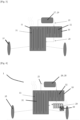
- This module 1 is used for the propulsion of an electric or hybrid vehicle.
- This module 1 here comprises an electric propulsion machine 2 having a rotor and a stator, a voltage converter 3 making it possible to electrically power the stator from the electrical energy supplied by an electrical energy storage unit, and a system of reduction 5 receiving the torque supplied by the rotor in order to propel the vehicle.
- the voltage converter 3 is shown as being at a distance from the electric propulsion machine 2 and the reduction system, for reasons of clarity of the drawing, but the voltage converter 3, the electric propulsion machine 2 and the reduction system 5 actually form a single block in the example considered.
- the electric propulsion machine 2 is a synchronous machine with a permanent magnet rotor, providing a nominal power of between 10 kW and 35 kW.
- the stator of this synchronous machine may comprise an electrical winding formed by conductors wound on the stator frame or by pins connected together.
- the electrical stator winding is for example a three-phase winding or a winding formed by two three-phase windings.
- the voltage converter 3 is an inverter/rectifier for converting the direct voltage of the electrical energy storage unit into an alternating voltage to electrically power the stator of the electric propulsion machine 2 in a propulsion mode of the vehicle, and for rectifying the alternating voltage induced at the terminals of the stator of the electric propulsion machine 2 in a regenerative mode.
- the voltage converter 3 for example implements several switching arms, each arm comprising controllable switches, for example field effect transistors or IGBT transistors.
- the voltage converter 3 receives or applies, depending on the propulsion or regenerative mode, a voltage to an electrical energy storage unit which has, for example, a nominal voltage of between 42V and 54V, for example a nominal voltage of 48V.
- the reduction system 5 comprises, in the example described, several gears meshing to transmit the torque supplied by the electric machine 2 to the wheels of the vehicle.
- the gears of the reduction system 5 are, for example, configured so that a single ratio is possible, or alternatively so that two distinct ratios or three distinct ratios are possible.
- module 1 is installed on a vehicle axle, whether it is the front axle or the rear axle of the vehicle, as shown in the Figures 3 and 4 .
- This module 1 is for example screwed onto this train or linked through silent blocks on this train.
- the output torque of the reduction system 5 is distributed between the different wheels 35 of this train by a differential.
- This module 1 comprises a first housing part 10 receiving the electric propulsion machine 2 and the voltage converter 3, as can be clearly seen in the Figure 2 .
- This first housing part 10 can be in one piece or be formed by assembling housing sub-parts together.
- the module 1 also comprises a second housing part 11 receiving the reduction system 5.
- the first housing part 10 and the second housing part 11 are here rigidly fixed, for example via screws.
- module 1 defines a cooling circuit 15 allowing the circulation of the same liquid which is here oil in the first 10 and the second 11 part of the housing. This liquid thus makes it possible to cool the electric propulsion machine 2 and the voltage converter 3 by taking calories from the latter.
- two parallel branches 22 and 23 can be provided in the cooling circuit 15, so that the oil circulates in the first part of the housing directly in contact with the rotor and also directly in contact with the stator of the electric propulsion machine 2.
- the cooling circuit is devoid of parallel branches and only one of the rotor and the stator of the electric machine 2 is directly in contact with the oil.
- the pump can be mounted inside or outside the module.
- the pump control system 27 may be mounted in whole or in part on the electronic board of the voltage converter 3, and the sensor electronics 28 may also be mounted on the electronic board of the voltage converter. This adds several functionalities to the electronic board of the voltage converter 3 in order to reduce the space requirement associated with the module.
- the cooling circuit 15 comprises the aforementioned pump 27 and filter 29, the latter can be arranged in the second portion of connection 21 of the circuit, so as to be arranged upstream of the heat sources in the circuit which are formed by the electric propulsion machine 2 and the voltage converter 3.
- the first connecting portion 20 of the cooling circuit provides a simple junction function between the housing parts 10 and 11. But the invention is not limited thereto, as will now be seen with reference to the Figure 4 .
- the first connecting portion 20 allows heat dissipation towards the outside of the module.
- This dissipation is for example provided by a radiator 30 associated with the first connecting portion 20 or via the production of this first connecting portion 20 in the form of a coil.
- a fan may be present on the module.
- the control system of this fan may be mounted in whole or in part on the electronic card of the voltage converter 3.
- the cooling circuit 15 cooperates with cooling reliefs 31 to dissipate to the outside of the module 1 the heat released by the electric propulsion machine 2 and by the voltage converter 3, as explained below.
- cooling reliefs 31 are carried by the surface of the second housing part 11.
- these cooling reliefs are fins made in one piece with the second housing part 11.
- cooling reliefs 32 which are also fins, are carried by the surface of the first housing part 10.
- the entire surface of the first housing part 10 and the entire surface of the second housing part 11 may carry fins. The use of fins makes it possible to promote the dissipation towards the outside of the module 1 of the heat collected by the oil during its passage through the first housing part 10 and the second housing part 11.
- the fins may all have the same shape, whether carried by the first housing part 10 or by the second housing part 11, and be spaced at a constant pitch.
- the fins may or may not be arranged in a staggered pattern from one row to the next.
Landscapes
- Engineering & Computer Science (AREA)
- Transportation (AREA)
- Mechanical Engineering (AREA)
- Power Engineering (AREA)
- Life Sciences & Earth Sciences (AREA)
- Combustion & Propulsion (AREA)
- Chemical & Material Sciences (AREA)
- Sustainable Development (AREA)
- Sustainable Energy (AREA)
- Electric Propulsion And Braking For Vehicles (AREA)
- Motor Or Generator Cooling System (AREA)
- Cooling, Air Intake And Gas Exhaust, And Fuel Tank Arrangements In Propulsion Units (AREA)
- Hybrid Electric Vehicles (AREA)
- Arrangement Or Mounting Of Propulsion Units For Vehicles (AREA)
- Connection Of Motors, Electrical Generators, Mechanical Devices, And The Like (AREA)
Applications Claiming Priority (3)
| Application Number | Priority Date | Filing Date | Title |
|---|---|---|---|
| FR1900545A FR3091838B1 (fr) | 2019-01-22 | 2019-01-22 | Module de propulsion d’un véhicule électrique ou hybride |
| EP20702216.1A EP3914470B1 (de) | 2019-01-22 | 2020-01-14 | Antriebsmodul für ein elektrisches oder hybrides fahrzeug |
| PCT/EP2020/050796 WO2020151996A1 (fr) | 2019-01-22 | 2020-01-14 | Module de propulsion d'un vehicule electrique ou hybride |
Related Parent Applications (2)
| Application Number | Title | Priority Date | Filing Date |
|---|---|---|---|
| EP20702216.1A Division EP3914470B1 (de) | 2019-01-22 | 2020-01-14 | Antriebsmodul für ein elektrisches oder hybrides fahrzeug |
| EP20702216.1A Division-Into EP3914470B1 (de) | 2019-01-22 | 2020-01-14 | Antriebsmodul für ein elektrisches oder hybrides fahrzeug |
Publications (2)
| Publication Number | Publication Date |
|---|---|
| EP4538084A2 true EP4538084A2 (de) | 2025-04-16 |
| EP4538084A3 EP4538084A3 (de) | 2025-07-09 |
Family
ID=67660172
Family Applications (2)
| Application Number | Title | Priority Date | Filing Date |
|---|---|---|---|
| EP20702216.1A Active EP3914470B1 (de) | 2019-01-22 | 2020-01-14 | Antriebsmodul für ein elektrisches oder hybrides fahrzeug |
| EP25158095.7A Pending EP4538084A3 (de) | 2019-01-22 | 2020-01-14 | Antriebsmodul eines elektrischen oder hybridfahrzeugs |
Family Applications Before (1)
| Application Number | Title | Priority Date | Filing Date |
|---|---|---|---|
| EP20702216.1A Active EP3914470B1 (de) | 2019-01-22 | 2020-01-14 | Antriebsmodul für ein elektrisches oder hybrides fahrzeug |
Country Status (8)
| Country | Link |
|---|---|
| EP (2) | EP3914470B1 (de) |
| JP (1) | JP2022518046A (de) |
| CN (2) | CN114604106A (de) |
| ES (1) | ES3030863T3 (de) |
| FR (1) | FR3091838B1 (de) |
| HU (1) | HUE071492T2 (de) |
| PL (1) | PL3914470T3 (de) |
| WO (1) | WO2020151996A1 (de) |
Families Citing this family (6)
| Publication number | Priority date | Publication date | Assignee | Title |
|---|---|---|---|---|
| EP3403615A1 (de) | 2017-05-17 | 2018-11-21 | Aorticlab Sarl | Transkatheterventilprothese für blutgefäss |
| FR3126660A1 (fr) | 2021-09-03 | 2023-03-10 | Valeo Embrayages | Système de propulsion pour véhicule hybride |
| FR3126661A1 (fr) | 2021-09-03 | 2023-03-10 | Valeo Embrayages | Système de propulsion pour véhicule hybride |
| FR3128165B1 (fr) | 2021-10-14 | 2023-09-08 | Valeo Embrayages | Système de propulsion de véhicule électrique ou hybride |
| FR3136132A1 (fr) | 2022-05-24 | 2023-12-01 | Valeo Equipements Electriques Moteur | Système de propulsion pour véhicule |
| CN118219812A (zh) | 2022-12-19 | 2024-06-21 | 法雷奥新能源汽车德国有限责任公司 | 车辆冷却系统和车辆 |
Citations (1)
| Publication number | Priority date | Publication date | Assignee | Title |
|---|---|---|---|---|
| DE102010048131A1 (de) * | 2010-10-11 | 2012-04-12 | Magna Powertrain Ag & Co. Kg | Elektrische Antriebseinheit |
Family Cites Families (22)
| Publication number | Priority date | Publication date | Assignee | Title |
|---|---|---|---|---|
| US903063A (en) | 1908-11-03 | Draper Co | Attachment for spinning-frames. | |
| JP3886696B2 (ja) * | 1999-04-27 | 2007-02-28 | アイシン・エィ・ダブリュ株式会社 | 駆動装置 |
| WO2002085659A1 (de) * | 2001-04-24 | 2002-10-31 | Voith Turbo Gmbh & Co. Kg | Antriebseinheit mit integriertem elektromotor |
| JP3941423B2 (ja) | 2001-06-15 | 2007-07-04 | トヨタ自動車株式会社 | 車両用パワーコントロールユニット |
| JP4267373B2 (ja) * | 2003-05-30 | 2009-05-27 | 株式会社日本自動車部品総合研究所 | 車両用電動機冷却システム |
| KR100527462B1 (ko) | 2003-06-26 | 2005-11-09 | 현대자동차주식회사 | 차량용 42볼트 벨트형 통합 발전기 시동기 시스템 |
| JP2005253167A (ja) * | 2004-03-03 | 2005-09-15 | Hitachi Ltd | 車両駆動装置及びそれを用いた電動4輪駆動車両 |
| JP3893395B2 (ja) * | 2005-01-28 | 2007-03-14 | モトール自動車株式会社 | ハイブリッド電気自動車の駆動制御装置 |
| JP4539531B2 (ja) * | 2005-10-26 | 2010-09-08 | トヨタ自動車株式会社 | 車両の駆動装置 |
| JP4850564B2 (ja) * | 2006-04-06 | 2012-01-11 | 日立オートモティブシステムズ株式会社 | 電力変換装置 |
| DE102011076525A1 (de) * | 2011-05-26 | 2012-11-29 | Zf Friedrichshafen Ag | Elektrischer Fahrantrieb für ein Fahrzeug |
| EP2549846A1 (de) * | 2011-07-22 | 2013-01-23 | Siemens Aktiengesellschaft | Temperieren der Antriebskomponenten eines Fahrzeugs |
| DE102011081511B4 (de) * | 2011-08-24 | 2017-06-22 | Fraunhofer-Gesellschaft zur Förderung der angewandten Forschung e.V. | Radnabenantriebssystem mit integriertem Kühlsystem |
| WO2013093986A1 (ja) * | 2011-12-24 | 2013-06-27 | 川崎重工業株式会社 | 電動車両 |
| US9579965B2 (en) * | 2012-01-31 | 2017-02-28 | Ford Global Technologies, Llc | Modular powertrain component for hybrid electric vehicles |
| JP2014007884A (ja) * | 2012-06-26 | 2014-01-16 | Aisin Seiki Co Ltd | 電動ユニットの冷却装置 |
| DE102013204766B4 (de) * | 2013-03-19 | 2018-07-05 | Robert Bosch Gmbh | Elektrische Fahrzeugachsenvorrichtung |
| JP6156186B2 (ja) * | 2014-02-25 | 2017-07-05 | マツダ株式会社 | 冷却システム |
| JP2017074858A (ja) * | 2015-10-15 | 2017-04-20 | 株式会社エクセディ | モータユニット |
| FR3042658B1 (fr) * | 2015-10-15 | 2017-10-27 | Renault Sas | Dispositif de gestion thermique d'un groupe motopropulseur electrique. |
| JP6149987B2 (ja) * | 2015-11-24 | 2017-06-21 | トヨタ自動車株式会社 | 車両用冷却装置 |
| EP3750729B1 (de) | 2018-02-12 | 2023-06-07 | BYD Company Limited | Antriebsaggregat und damit ausgestattetes fahrzeug |
-
2019
- 2019-01-22 FR FR1900545A patent/FR3091838B1/fr active Active
-
2020
- 2020-01-14 CN CN202210265821.2A patent/CN114604106A/zh active Pending
- 2020-01-14 EP EP20702216.1A patent/EP3914470B1/de active Active
- 2020-01-14 JP JP2021542447A patent/JP2022518046A/ja not_active Ceased
- 2020-01-14 ES ES20702216T patent/ES3030863T3/es active Active
- 2020-01-14 CN CN202080010256.4A patent/CN113329907A/zh active Pending
- 2020-01-14 PL PL20702216.1T patent/PL3914470T3/pl unknown
- 2020-01-14 WO PCT/EP2020/050796 patent/WO2020151996A1/fr not_active Ceased
- 2020-01-14 EP EP25158095.7A patent/EP4538084A3/de active Pending
- 2020-01-14 HU HUE20702216A patent/HUE071492T2/hu unknown
Patent Citations (1)
| Publication number | Priority date | Publication date | Assignee | Title |
|---|---|---|---|---|
| DE102010048131A1 (de) * | 2010-10-11 | 2012-04-12 | Magna Powertrain Ag & Co. Kg | Elektrische Antriebseinheit |
Also Published As
| Publication number | Publication date |
|---|---|
| CN114604106A (zh) | 2022-06-10 |
| PL3914470T3 (pl) | 2025-09-15 |
| JP2022518046A (ja) | 2022-03-11 |
| HUE071492T2 (hu) | 2025-09-28 |
| EP3914470C0 (de) | 2025-03-26 |
| EP4538084A3 (de) | 2025-07-09 |
| CN113329907A (zh) | 2021-08-31 |
| WO2020151996A1 (fr) | 2020-07-30 |
| ES3030863T3 (en) | 2025-07-02 |
| EP3914470A1 (de) | 2021-12-01 |
| FR3091838B1 (fr) | 2021-02-12 |
| EP3914470B1 (de) | 2025-03-26 |
| FR3091838A1 (fr) | 2020-07-24 |
Similar Documents
| Publication | Publication Date | Title |
|---|---|---|
| EP3914470B1 (de) | Antriebsmodul für ein elektrisches oder hybrides fahrzeug | |
| EP3044856B1 (de) | Schutzabdeckung für eine elektrische drehmaschine für ein kraftfahrzeug | |
| EP3044858B1 (de) | Elektronische baugruppe für eine elektrische drehmaschine für ein kraftfahrzeug | |
| FR2945679A1 (fr) | Machine rotative electrique | |
| EP2656487B1 (de) | Spannungsregler für eine elektrische drehmaschine, lager für eine solche maschine mit einer solchen vorrichtung und solche maschine mit einem lager | |
| FR2896348A1 (fr) | Machine dynamoelectrique a dispositif de commande integre | |
| FR2889777A1 (fr) | Machine electrique rotative en tandem | |
| EP3501908A1 (de) | Elektrische ausrüstung mit versetzter wand | |
| EP3258579A1 (de) | Umlaufende elektrische maschine mit verbesserter leistungselektronik | |
| EP2913910B1 (de) | Rotierende elektrische Maschine für ein Kraftfahrzeug umfassend eine Elektronikeinheit | |
| FR3096525A1 (fr) | Module de propulsion d’un véhicule électrique ou hybride | |
| FR3096524A1 (fr) | Module de propulsion d’un véhicule électrique ou hybride | |
| FR3084622A1 (fr) | Architecture de traction comportant des machines electriques basse tension integrees dans les roues d'un vehicule automobile | |
| FR3078842A1 (fr) | Machine electrique rotative | |
| FR3065335A1 (fr) | Machine electrique tournante munie d'un interconnecteur a connexion de point neutre integree | |
| EP3917301B1 (de) | Wechselrichtergerät | |
| EP3727944B1 (de) | Elektrisch leitendes teil für eine elektrische anordnung | |
| FR2714773A1 (fr) | Moteur synchrone à aimants permanents et à commutation électronique. | |
| FR2969413A1 (fr) | Dispositif regulateur de tension pour une machine electrique tournante, palier d'une telle machine equipe d'un tel dispositif et une telle machine comportant un tel palier | |
| EP3843249A1 (de) | Elektronisches modul für elektrisch umlaufende maschine | |
| US12592619B2 (en) | Rotor shaft-mounted vapor chambers and heat pipes with endcap heat sinks for electric machines | |
| WO2021074405A1 (fr) | Système électronique d'alimentation d'une machine électrique et ensemble électrique comprenant un tel système électronique | |
| FR3144722A1 (fr) | Convertisseur de tension assurant une fonction de raccordement électrique de puissance | |
| FR3109560A1 (fr) | Ensemble de propulsion d’un véhicule électrique ou hybride | |
| EP4360411A1 (de) | Elektronikeinheit für einen spannungswandler einer rotierenden elektrischen maschine |
Legal Events
| Date | Code | Title | Description |
|---|---|---|---|
| PUAI | Public reference made under article 153(3) epc to a published international application that has entered the european phase |
Free format text: ORIGINAL CODE: 0009012 |
|
| STAA | Information on the status of an ep patent application or granted ep patent |
Free format text: STATUS: REQUEST FOR EXAMINATION WAS MADE |
|
| 17P | Request for examination filed |
Effective date: 20250214 |
|
| AC | Divisional application: reference to earlier application |
Ref document number: 3914470 Country of ref document: EP Kind code of ref document: P |
|
| AK | Designated contracting states |
Kind code of ref document: A2 Designated state(s): AL AT BE BG CH CY CZ DE DK EE ES FI FR GB GR HR HU IE IS IT LI LT LU LV MC MK MT NL NO PL PT RO RS SE SI SK SM TR |
|
| REG | Reference to a national code |
Ref country code: DE Ref legal event code: R079 Free format text: PREVIOUS MAIN CLASS: B60K0006405000 Ipc: B60L0050600000 |
|
| PUAL | Search report despatched |
Free format text: ORIGINAL CODE: 0009013 |
|
| AK | Designated contracting states |
Kind code of ref document: A3 Designated state(s): AL AT BE BG CH CY CZ DE DK EE ES FI FR GB GR HR HU IE IS IT LI LT LU LV MC MK MT NL NO PL PT RO RS SE SI SK SM TR |
|
| RIC1 | Information provided on ipc code assigned before grant |
Ipc: H02K 11/33 20160101ALI20250604BHEP Ipc: H02K 9/19 20060101ALI20250604BHEP Ipc: H02K 7/00 20060101ALI20250604BHEP Ipc: H02K 5/20 20060101ALI20250604BHEP Ipc: B60L 15/00 20060101ALI20250604BHEP Ipc: B60K 6/405 20071001ALI20250604BHEP Ipc: B60K 6/40 20071001ALI20250604BHEP Ipc: B60L 50/60 20190101AFI20250604BHEP |
|
| STAA | Information on the status of an ep patent application or granted ep patent |
Free format text: STATUS: EXAMINATION IS IN PROGRESS |
|
| 17Q | First examination report despatched |
Effective date: 20260316 |