EP4535563A1 - Elektronische vorrichtung - Google Patents
Elektronische vorrichtung Download PDFInfo
- Publication number
- EP4535563A1 EP4535563A1 EP23811626.3A EP23811626A EP4535563A1 EP 4535563 A1 EP4535563 A1 EP 4535563A1 EP 23811626 A EP23811626 A EP 23811626A EP 4535563 A1 EP4535563 A1 EP 4535563A1
- Authority
- EP
- European Patent Office
- Prior art keywords
- antenna
- electronic device
- feed point
- radiating elements
- directivity
- Prior art date
- Legal status (The legal status is an assumption and is not a legal conclusion. Google has not performed a legal analysis and makes no representation as to the accuracy of the status listed.)
- Pending
Links
Images


Classifications
-
- G—PHYSICS
- G01—MEASURING; TESTING
- G01S—RADIO DIRECTION-FINDING; RADIO NAVIGATION; DETERMINING DISTANCE OR VELOCITY BY USE OF RADIO WAVES; LOCATING OR PRESENCE-DETECTING BY USE OF THE REFLECTION OR RERADIATION OF RADIO WAVES; ANALOGOUS ARRANGEMENTS USING OTHER WAVES
- G01S7/00—Details of systems according to groups G01S13/00, G01S15/00, G01S17/00
- G01S7/02—Details of systems according to groups G01S13/00, G01S15/00, G01S17/00 of systems according to group G01S13/00
- G01S7/03—Details of HF subsystems specially adapted therefor, e.g. common to transmitter and receiver
-
- H—ELECTRICITY
- H01—ELECTRIC ELEMENTS
- H01Q—ANTENNAS, i.e. RADIO AERIALS
- H01Q3/00—Arrangements for changing or varying the orientation or the shape of the directional pattern of the waves radiated from an antenna or antenna system
- H01Q3/24—Arrangements for changing or varying the orientation or the shape of the directional pattern of the waves radiated from an antenna or antenna system varying the orientation by switching energy from one active radiating element to another, e.g. for beam switching
-
- G—PHYSICS
- G01—MEASURING; TESTING
- G01S—RADIO DIRECTION-FINDING; RADIO NAVIGATION; DETERMINING DISTANCE OR VELOCITY BY USE OF RADIO WAVES; LOCATING OR PRESENCE-DETECTING BY USE OF THE REFLECTION OR RERADIATION OF RADIO WAVES; ANALOGOUS ARRANGEMENTS USING OTHER WAVES
- G01S13/00—Systems using the reflection or reradiation of radio waves, e.g. radar systems; Analogous systems using reflection or reradiation of waves whose nature or wavelength is irrelevant or unspecified
- G01S13/88—Radar or analogous systems specially adapted for specific applications
- G01S13/93—Radar or analogous systems specially adapted for specific applications for anti-collision purposes
- G01S13/931—Radar or analogous systems specially adapted for specific applications for anti-collision purposes of land vehicles
Definitions
- the present disclosure relates to an electronic device.
- Patent Literature 1 teaches that a forward detection radar attached to the front of a vehicle can reduce unwanted reflection from the road surface by orienting the directivity of the antenna upward in order to reduce downward gain.
- Patent Literature 2 proposes a configuration in which an antenna aperture is made larger by increasing the spacing between antennas to obtain good angular accuracy for a forward detection radar attached to the front of a vehicle while minimizing redundancy.
- an electronic device includes a first antenna, a second antenna, and a controller.
- the first antenna has a directivity in a first direction.
- the second antenna has a directivity in a second direction including a component in a direction different from the first direction.
- the controller is configured to control the first antenna and the second antenna.
- the controller is configured to perform control so as to be able to switch between a first mode in which either the first antenna or the second antenna is made to operate and a second mode in which both the first antenna and the second antenna are made to operate.
- an "electronic device” may be a device that is driven by electric power.
- An electronic device may include a transmission antenna and a reception antenna.
- the electronic device transmits an electromagnetic wave as a transmission wave from the transmission antenna.
- a prescribed object is present in the surroundings of the electronic device according to an embodiment, at least part of a transmission wave transmitted from the electronic device will be reflected by the object and become a reflection wave.
- the reflection wave is then received by the reception antenna of the electronic device, and in this way, the electronic device is able to detect the object.
- the electronic device can measure the distance to the prescribed object.
- the electronic device can also measure the relative velocity of the prescribed object.
- the electronic device according to an embodiment can also measure the direction in which the reflection wave from the prescribed object arrives at the electronic device (angle of arrival).
- the electronic device can, for example, be installed in a roadside machine that monitors the operation statuses of vehicles (moving objects), such as automobiles, and detect a prescribed object such as a moving object present in the surroundings of the roadside machine.
- the electronic device can be installed in any device such as a traffic signal and detect a prescribed object such as a moving object present in the surroundings of the device.
- the electronic device according to an embodiment may typically be a RADAR (radio detecting and ranging) sensor that transmits and receives radio waves.
- the electronic device according to an embodiment is not limited to a radar sensor. These kind of sensors may include patch antennas, for example. Since technologies such as RADAR are already well known, detailed description thereof may be simplified or omitted as appropriate.
- the electronic device according to an embodiment may, for example, use an LED or laser as a light source.
- the electronic device according to an embodiment may, for example, use a photodiode as a light-receiving element.
- the electronic device according to an embodiment may, for example, use a lens in order to control directivity.
- an electronic device having improved convenience in technologies for detecting objects such as millimeter wave radar.
- an electronic device having improved convenience in technologies for detecting objects such as millimeter wave radar, can be provided.
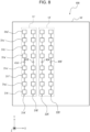
- FIGs. 8 and 9 are diagrams illustrating the configuration of an electronic device according to a comparative example of an embodiment.
- FIG. 8 is a diagram in which an electronic device according to a comparative example of an embodiment is viewed in a prescribed direction.
- FIG. 9 is a diagram in which the electronic device according to the comparative example of an embodiment is viewed in an opposite direction from the prescribed direction in FIG. 8 .
- an X-axis direction may be a horizontal direction or a left-right direction.
- a Y-axis direction may be vertical direction or an up-down direction.
- a positive Y-axis direction may be an up direction and a negative Y-axis direction may be a down direction.
- a Z-axis direction may be a front-back direction.
- a positive Z-axis direction may be a front direction or a forward direction and a negative Z-axis direction may be a back direction.
- an electronic device 100 may include a substrate 10'.
- the substrate 10' may be a circuit board used for ordinary electrical circuits or electronic circuits.
- the surface of the substrate 10' illustrated in FIG. 8 i.e., the surface of the substrate 10' on the positive Z-axis direction side
- the surface of the substrate 10' illustrated in FIG. 9 is also referred to as a back-side surface or back surface for convenience.
- FIGs. 8 and 9 illustrate the functional parts of a transmission system of the electronic device 100, and illustration of the functional parts of a reception system of the electronic device 100 is omitted.
- the electronic device 100 includes a first antenna 11' and a second antenna 12' on the front surface of the substrate 10'.
- the first antenna 11' and the second antenna 12' may be planar antennas (patch antennas) commonly used in millimeter radar.
- the first antenna 11' includes a radiating element group 21A' and a radiating element group 21B'.
- the second antenna 12' includes a radiating element group 22A' and a radiating element group 22B'.
- a feed point 41A' of the radiating element group 21A' supplies power to the radiating element group 21A'.
- a feed point 41B' of the radiating element group 21B' supplies power to the radiating element group 21B'.
- a feed point 42A' of the radiating element group 22A' supplies power to the radiating element group 22A'.
- a feed point 42B' of the radiating element group 22B' supplies power to the radiating element group 22B'.
- the feed point 41A', the feed point 41B', the feed point 42A', and the feed point 42B' each supply power from the back-side surface of the substrate 10' illustrated in FIG. 9 to the front-side surface of the substrate 10' illustrated in FIG. 8 .
- the radiating element group 21A' includes multiple radiating elements 31a' to 31d' arranged in a vertical direction, and multiple radiating elements 31e' to 31h' arranged in a vertical direction. Each of these radiating elements may be composed of a metal material such as copper.
- the radiating elements 31a' to 31d' may be electrically connected to each other by being wired in series with each other.
- the wiring lines with which the radiating elements 31a' to 31d' are wired in series with each other may have the same length as each other.
- each of the wiring lines wiring the radiating elements 31a' to 31d' in series with each other may have a length the same as a wavelength ⁇ of a transmission wave to be transmitted from the radiating element group 21A'.
- the radiating elements 31e' to 31h' may be electrically connected in series with each other by being wired in series with each other.
- the wiring lines with which the radiating elements 31e' to 31h' are wired in series with each other may have the same length as each other.
- each of the wiring lines wiring the radiating elements 31e' to 31h' in series with each other may have a length the same as the wavelength ⁇ of a transmission wave to be transmitted from the radiating element group 21A'.
- the feed point 41A' may be electrically connected to the radiating element 31a' by being wired to the radiating element 31a'.
- the wiring line connecting the feed point 41A' to the radiating element 31a' may have a length the same as the wavelength ⁇ of transmission waves transmitted from the radiating element group 21A', for example.
- the feed point 41A' may be electrically connected to the radiating element 31e' by being wired to the radiating element 31e'.
- the wiring line connecting the feed point 41A' to the radiating element 31e' may have a length the same as the wavelength ⁇ of transmission waves transmitted from the radiating element group 21A', for example.
- the phases of transmission waves transmitted from the radiating element group 21A' in other words, transmission waves transmitted from the radiating elements 31a' to 31d' and the radiating elements 31e' to 31h' can be made to match each other.
- the radiating element group 21B', the radiating element group 22A', and the radiating element group 22B' may have the same configuration or a similar configuration to the radiating element group 21A'.
- the electronic device 100 includes a controller 50' on the back surface of the substrate 10'.
- the electronic device 100 further includes a feed point 61A', a feed point 61B', a feed point 62A', and a feed point 62B' on the back surface of the substrate 10'.
- the controller 50' can control overall operation of the electronic device 100 including control of each functional part of the electronic device 100.
- the controller 50' may include at least one processor, such as a CPU (central processing unit) or a DSP (digital signal processor), in order to provide control and processing power to perform various functions.
- the controller 50' may be implemented collectively in a single processor, in several processors, or in individual processors.
- the processors may be implemented as a single integrated circuit. An integrated circuit may also be referred to as an IC.
- Processors may be implemented as multiple integrated circuits and discrete circuits connected so as to be able to communicate with each other.
- the processors may be realized based on various other known technologies.
- the controller 50' may be configured, for example, as a CPU and a program executed by the CPU.
- the controller 50' may configured as any SoC (system on a chip) or the like.
- the controller 50' may include any memory as appropriate.
- any memory may store various parameters for defining transmission waves to be transmitted from the first antenna 11' and/or the second antenna 12'.
- the feed point 61A' illustrated in FIG. 9 is electrically connected to the feed point 41A' illustrated in FIG. 8 .
- the feed point 61B' illustrated in FIG. 9 is electrically connected to the feed point 41B' illustrated in FIG. 8 .
- the feed point 62A' illustrated in FIG. 9 is electrically connected to the feed point 42A' illustrated in FIG. 8 .
- the feed point 62B' illustrated in FIG. 9 is electrically connected to the feed point 42B' illustrated in FIG. 8 .
- the feed point 61A', the feed point 61B', the feed point 62A', and the feed point 62B' may be respectively connected to the feed point 41A', the feed point 41B', the feed point 42A', and the feed point 42B' via through holes drilled in the substrate 10', for example.
- the feed point 61A' and the feed point 61B' may be electrically connected to each other by being wired together.
- the feed point 62A' and the feed point 62B' may be electrically connected to each other by being wired together.
- the midpoint of a wiring line connecting the feed point 61A' to the feed point 61B' may be electrically connected to an RF (radio frequency) port 51' of the controller 50' by a wiring line 91'.
- the midpoint of a wiring line connecting the feed point 62A' to the feed point 62B' may be electrically connected to an RF (radio frequency) port 52' of the controller 50' by a wiring line 92'.
- the length of the wiring line 91' may be the same as the length of the wiring line 92'.
- the first antenna 11' and the second antenna 12' of the electronic device 100 may transmit radio waves of a frequency band such as millimeter waves (greater than or equal to 30 GHz) or quasi-millimeter waves (for example, around 20 GHz to 30 GHz).
- the first antenna 11' and the second antenna 12' of the electronic device 100 may transmit radio waves with a frequency bandwidth of 4 GHz, such as from 77 GHz to 81 GHz.
- transmission signals for transmitting such transmission waves may be generated by the controller 50', for example.
- FMCW radar frequency-modulated continuous wave radar
- the transmission signal is generated by sweeping the frequency of the transmitted radio waves. Therefore, for example, in a millimeter-wave FMCW radar that uses radio waves in the 79 GHz frequency band, the frequency of the radio waves used will have a frequency bandwidth of 4 GHz, for example, from 77 GHz to 81 GHz.
- Radar in the 79 GHz frequency band is characterized by having a wider usable frequency bandwidth than other millimeter/quasi-millimeter wave radars, for example, in the 24 GHz, 60 GHz, and 76 GHz frequency bands.
- the feed point 41A, the feed point 41B, the feed point 41C, and the feed point 41D, and the feed point 42A, the feed point 42B, the feed point 42C, and the feed point 42D each supply power from the back-side surface of the substrate 10 illustrated in FIG. 2 to the front-side surface of the substrate 10 illustrated in FIG. 1 .
- the radiating element group 21A includes multiple radiating elements 31a to 31d arranged in a vertical direction.
- the radiating element group 22A includes multiple radiating elements 32a to 32d arranged in a vertical direction. Each of these radiating elements may be composed of a metal material such as copper.
- the radiating elements 31a to 31d may be electrically connected to each other by being wired in series with each other.
- the wiring lines with which the radiating elements 31a to 31d are wired in series with each other may have the same length as each other.
- each of the wiring lines wiring the radiating elements 31a to 31d in series with each other may have a length that is different from an integer multiple of a wavelength ⁇ of a transmission wave to be transmitted from the radiating element group 21A.
- the radiating elements 32a to 32d may be electrically connected in series with each other by being wired in series with each other.
- the wiring lines with which the radiating elements 32a to 32d are wired in series with each other may have the same length as each other.
- each of the wiring lines wiring the radiating elements 32a to 32d in series with each other may have a length that is different from an integer multiple of a wavelength ⁇ of a transmission wave to be transmitted from the radiating element group 22A.
- each of the wiring lines wiring the radiating elements 32a to 32d in series with each other may have a length such as (3/4) ⁇ with ⁇ being the wavelength of a transmission wave to be transmitted from the radiating element group 22A.
- the length of wiring lines connecting adjacent radiating elements to each other may be different from an integer multiple of the wavelength ⁇ of the transmission waves.
- the phase of transmission waves transmitted from the radiating elements 32a to 32d can be shifted.
- multiple radiating elements may be connected to each other with a uniform spacing by wiring lines.
- multiple radiating elements may be connected to each other with a spacing different from an integer multiple of the wavelength ⁇ of the transmission wave or reception wave.
- the first antenna 11 includes a configuration in which multiple radiating elements (for example, 31a to 31d) are connected to each other in series in a linear manner.
- the second antenna 12 includes a configuration in which multiple radiating elements are connected to each other in series in a linear manner parallel to the first antenna 11.
- the spacing of the radiating elements of the first antenna 11 and the spacing of the radiating elements of the second antenna 12 may be different from each other.
- the feed point 41A may be electrically connected to the radiating element 31a. With this configuration, the phases of transmission waves transmitted from the radiating element group 21A, i.e., from the radiating elements 31a to 31d, can be each shifted by the same amount.
- the radiating element group 21B, the radiating element group 21C, and the radiating element group 21D may have the same configuration or a similar configuration to the radiating element group 21A.
- the feed point 41B may be electrically connected to the radiating elements constituting the radiating element group 21B.
- the feed point 41C may be electrically connected to the radiating elements constituting the radiating element group 21C.
- the feed point 41D may be electrically connected to the radiating elements constituting the radiating element group 21D.
- the feed point 42A may be electrically connected to the radiating element 32a. With this configuration, the phases of transmission waves transmitted from the radiating element group 22A, i.e., from the radiating elements 32a to 32d, can be each shifted by the same amount.
- the radiating element group 22B, the radiating element group 22C, and the radiating element group 22D may have the same configuration or a similar configuration to the radiating element group 22A.
- the feed point 42B may be electrically connected to the radiating elements constituting the radiating element group 22B.
- the feed point 42C may be electrically connected to the radiating elements constituting the radiating element group 22C.
- the feed point 42D may be electrically connected to the radiating elements constituting the radiating element group 22D.
- the electronic device 1 includes a controller 50 on the back surface of the substrate 10.
- the electronic device 1 further includes a feed point 61A, a feed point 61B, a feed point 61C, and a feed point 61D, and a feed point 62A, a feed point 62B, a feed point 62C, and a feed point 62D on the back surface of the substrate 10.
- the controller 50 can control overall operation of the electronic device 1 including control of each functional part of the electronic device 1.
- the controller 50 may control operation of the first antenna 11 and the second antenna 12.
- the controller 50 may include at least one processor, such as a CPU (central processing unit) or a DSP (digital signal processor), in order to provide control and processing power to perform various functions.
- the controller 50 may be implemented collectively in a single processor, in several processors, or in individual processors.
- the processors may be implemented as a single integrated circuit. An integrated circuit may also be referred to as an IC.
- Processors may be implemented as multiple integrated circuits and discrete circuits connected so as to be able to communicate with each other.
- the processors may be realized based on various other known technologies.
- the controller 50 may be configured, for example, as a CPU and a program executed by the CPU.
- the controller 50 may configured as any SoC (system on a chip) or the like.
- the controller 50 may include any memory as appropriate.
- any memory may store various parameters for defining transmission waves to be transmitted from the first antenna 11 and/or the second antenna 12.
- the feed point 61A illustrated in FIG. 2 is electrically connected to the feed point 41A illustrated in FIG. 1 .
- the feed point 61B illustrated in FIG. 2 is electrically connected to the feed point 41B illustrated in FIG. 1 .
- the feed point 61C illustrated in FIG. 2 is electrically connected to the feed point 41C illustrated in FIG. 1 .
- the feed point 61D illustrated in FIG. 2 is electrically connected to the feed point 41D illustrated in FIG. 1 .
- the feed point 62A illustrated in FIG. 2 is electrically connected to the feed point 42A illustrated in FIG. 1 .
- the feed point 62B illustrated in FIG. 2 is electrically connected to the feed point 42B illustrated in FIG. 1 .
- the feed point 62D illustrated in FIG. 2 is electrically connected to the feed point 42C illustrated in FIG. 1 .
- the feed point 62D illustrated in FIG. 2 is electrically connected to the feed point 42D illustrated in FIG. 1 .
- the feed point 61A, the feed point 61B, the feed point 61C, and the feed point 61D may be respectively connected to the feed point 41A, the feed point 41B, the feed point 41C, and the feed point 41D via through holes drilled in the substrate 10, for example.
- the feed point 62A, the feed point 62B, the feed point 62C, and the feed point 62D may be respectively connected to the feed point 42A, the feed point 42B, the feed point 42C, and the feed point 42D via through holes drilled in the substrate 10, for example.
- the feed point 61A and the feed point 61B may be electrically connected to each other by being wired together.
- the feed point 61C and the feed point 61D may be electrically connected to each other by being wired together.
- the feed point 62A and the feed point 62B may be electrically connected to each other by being wired together.
- the feed point 62C and the feed point 62D may be electrically connected to each other by being wired together.
- the midpoint of a wiring line connecting the feed point 61A to the feed point 61B and the midpoint of a wiring line connecting the feed point 61C to the feed point 61D may be electrically connected to each other by a wiring line 71.
- the midpoint of a wiring line connecting the feed point 62A to the feed point 62B and the midpoint of a wiring line connecting the feed point 62C to the feed point 62D may be electrically connected to each other by a wiring line 72.
- the midpoint of the wiring line 71 may be electrically connected to an RF (radio frequency) port 51 of the controller 50 by a wiring line 81.
- the midpoint of the wiring line 72 may be electrically connected to an RF (radio frequency) port 52 of the controller 50 by a wiring line 82.
- the first antenna 11 and the second antenna 12 of the electronic device 1 may transmit radio waves of a frequency band such as millimeter waves or quasi-millimeter waves.
- the first antenna 11 and the second antenna 12 of the electronic device 1 may transmit radio waves with a frequency bandwidth of 4 GHz, such as from 77 GHz to 81 GHz.
- transmission signals for transmitting such transmission waves may be generated by the controller 50, for example.
- the electronic device 1 illustrated in FIG. 1 includes the same number of radiating elements as the electronic device 100 illustrated in FIG. 8 . However, in the electronic device 1 illustrated in FIG. 1 , the radiating elements connected to the RF port 51 and the RF port 52 of the controller 50 are different to those in the electronic device 100 illustrated in FIG. 8 . In the electronic device 1 illustrated in FIG. 1 , the sixteen radiating elements in the upper half constitute the first antenna 11 and the sixteen radiating elements in the lower half constitute the second antenna 12.
- the radiating elements constituting the radiating element group 21A etc. may have a length such as (3/4) ⁇ with ⁇ being the wavelength of the transmission wave.
- the length of wiring lines connecting adjacent radiating elements to each other different from an integer multiple of the wavelength ⁇ of the transmission waves, the phase of transmission waves transmitted from the radiating elements 31a to 31d etc. can be shifted. Therefore, the first antenna 11 as a whole has a directivity in a direction d1 illustrated in FIG.
- the first antenna 11 has a directivity in a first direction d1.
- the first antenna 11 may have a directivity in the first direction d1 due to multiple radiating elements being connected to each other with a spacing different from an integer multiple of the wavelength ⁇ of the transmission waves or reception waves.
- the first antenna 11 may have a directivity including a component in a vertically upward direction as the first direction d1.
- the radiating elements constituting the radiating element group 22A etc. may have a length such as (3/4) ⁇ with ⁇ being the wavelength of a transmission wave.
- the length of wiring lines connecting adjacent radiating elements to each other different from an integer multiple of the wavelength ⁇ of the transmission waves, the phase of transmission waves transmitted from the radiating elements 32a to 32d etc. can be shifted. Therefore, the second antenna 12 as a whole has a directivity in a direction d2 illustrated in FIG. 4 , for example, and can form a beam of transmission waves.
- the second antenna 12 has a directivity in a second direction d2 including a component in a direction different from the first direction d1.
- the second antenna 12 may have a directivity in the second direction d2 due to multiple radiating elements being connected to each other with a spacing different from an integer multiple of the wavelength ⁇ of the transmission waves or reception waves.
- the second antenna 12 may have a directivity including a component in a vertically downward direction as the second direction d2.
- the directivity of the composite wave is the combined directional vector of the directivities of the respective antennas. Therefore, the combination of transmission waves transmitted from both the first antenna 11 and the second antenna 12 (composite wave) has a directivity in the positive Z-axis direction, i.e., in the forward direction, as illustrated in FIG. 5 , and a beam of composite waves is formed in the positive Z-axis direction, i.e., in the forward direction.
- the main lobe of the composite wave transmitted from the first antenna 11 and the second antenna 12 is oriented in the positive Z-axis direction, i.e., in the forward direction (0° for both the X axis and Y axis) with respect to the surface of the substrate 10.
- the composite wave transmitted from the first antenna 11 and the second antenna 12 has a larger gain than a transmission wave transmitted from only the first antenna 11 or the second antenna 12. Therefore, objects can be detected with higher accuracy with a composite wave transmitted from the first antenna 11 and the second antenna 12 than with a transmission wave transmitted from only the first antenna 11 or the second antenna 12. In addition, objects that are farther away can be detected with a composite wave transmitted from the first antenna 11 and the second antenna 12 than with a transmission wave transmitted from only the first antenna 11 or the second antenna 12.
- the number of radiating elements arranged in the vertical direction of the radiating element group 21A is four as illustrated in FIG. 1 .
- the number of radiating elements arranged in the vertical direction of the radiating element group 21A' is eight as illustrated in FIG. 8 . Therefore, when a transmission wave is transmitted from either the first antenna 11 or the second antenna 12 in the electronic device 1, the directivity of the transmission wave can be made relatively wider compared to the electronic device 100.
- the controller 50 may have multiple operation modes. In the electronic device 1 according to an embodiment, the controller 50 may perform control so as to be able to switch between multiple operation modes. For example, the controller 50 performs control so as to be able to switch between a first mode and a second mode.
- the first mode may be a mode in which either the first antenna 11 or the second antenna 12 is made to operate.
- the controller 50 makes only the second antenna 12 operate as the first mode.
- the second mode may be a mode in which both the first antenna 11 and the second antenna 12 are made to operate.
- the directivity of radio waves obtained by combining radio waves from both the first antenna 11 and the second antenna 12 may be a third direction d3, which is different from both the first direction d1 and the second direction d2.
- the third direction d3 may be a direction perpendicular to an antenna substrate surface.
- the electronic device 1 can transmit a transmission wave having a relatively wide directivity in a downward (diagonally downward) direction, as illustrated in FIG. 4 , for example, by operating in the first mode.
- the electronic device 1 can transmit a transmission wave having a relatively narrow directivity in the forward direction (front direction) and a relatively high gain, as illustrated in FIG. 5 , for example, by operating in the second mode.
- the electronic device 1 can be used, for example, in a use case as a device that is installed in or near a roadside machine or a traffic signal and detects automobile and pedestrians etc. traveling along a road.
- the electronic device 1 provides a function of detecting automobiles etc. at relatively short distances below the device.
- the function of detecting automobiles etc. at positions relatively far away from the device in a direction close to a horizontal direction of the device is also realized.
- the electronic device 1 can change the direction of directivity.
- the electronic device 1 can switch the operation so as to change between wide and narrow directivities in addition to changing the direction of directivity. Therefore, in an embodiment, the electronic device 1 can have improved convenience in particular modes of use due to being able to switch between wide and narrow directivities in addition to being able to switch the direction of a beam of transmission waves or reception waves.
- FIG. 6 is a diagram illustrating an example configuration in which radiating elements are arranged in the vertical direction in a radiating element group.
- FIG. 7 is a diagram illustrating results obtained when simulating operation of an antenna in which the number of radiating elements arranged in the vertical direction is varied in the configuration illustrated in FIG. 6 .
- each radiating element was provided with a feed point, and the amplitude and phase of the transmission wave could be changed individually.
Landscapes
- Engineering & Computer Science (AREA)
- Computer Networks & Wireless Communication (AREA)
- Physics & Mathematics (AREA)
- General Physics & Mathematics (AREA)
- Radar, Positioning & Navigation (AREA)
- Remote Sensing (AREA)
- Variable-Direction Aerials And Aerial Arrays (AREA)
- Radar Systems Or Details Thereof (AREA)
Applications Claiming Priority (2)
| Application Number | Priority Date | Filing Date | Title |
|---|---|---|---|
| JP2022087184A JP7770993B2 (ja) | 2022-05-27 | 2022-05-27 | 電子機器 |
| PCT/JP2023/017617 WO2023228751A1 (ja) | 2022-05-27 | 2023-05-10 | 電子機器 |
Publications (1)
| Publication Number | Publication Date |
|---|---|
| EP4535563A1 true EP4535563A1 (de) | 2025-04-09 |
Family
ID=88919147
Family Applications (1)
| Application Number | Title | Priority Date | Filing Date |
|---|---|---|---|
| EP23811626.3A Pending EP4535563A1 (de) | 2022-05-27 | 2023-05-10 | Elektronische vorrichtung |
Country Status (3)
| Country | Link |
|---|---|
| EP (1) | EP4535563A1 (de) |
| JP (2) | JP7770993B2 (de) |
| WO (1) | WO2023228751A1 (de) |
Family Cites Families (7)
| Publication number | Priority date | Publication date | Assignee | Title |
|---|---|---|---|---|
| JPS61150504A (ja) * | 1984-12-25 | 1986-07-09 | Toshiba Corp | アンテナ装置 |
| JP2005043080A (ja) | 2003-07-23 | 2005-02-17 | Fujitsu Ten Ltd | 車両用レーダの取付方法、及び車両用レーダ |
| JP2008166855A (ja) * | 2005-04-14 | 2008-07-17 | Matsushita Electric Ind Co Ltd | 携帯電話機 |
| JP4682684B2 (ja) * | 2005-04-28 | 2011-05-11 | パナソニック株式会社 | デジタル信号受信装置 |
| JP2010093552A (ja) * | 2008-10-08 | 2010-04-22 | Sharp Corp | 受信装置、復調方法、受信制御プログラム、及び、記録媒体 |
| JP7092529B2 (ja) * | 2018-03-16 | 2022-06-28 | 株式会社デンソーテン | レーダ装置およびレーダ装置の制御方法 |
| US11360191B2 (en) * | 2019-12-27 | 2022-06-14 | Woven Planet North America, Inc. | Adaptive tilting radars for effective vehicle controls |
-
2022
- 2022-05-27 JP JP2022087184A patent/JP7770993B2/ja active Active
-
2023
- 2023-05-10 EP EP23811626.3A patent/EP4535563A1/de active Pending
- 2023-05-10 WO PCT/JP2023/017617 patent/WO2023228751A1/ja not_active Ceased
-
2025
- 2025-11-05 JP JP2025186555A patent/JP2026009357A/ja active Pending
Also Published As
| Publication number | Publication date |
|---|---|
| JP7770993B2 (ja) | 2025-11-17 |
| JP2026009357A (ja) | 2026-01-19 |
| WO2023228751A1 (ja) | 2023-11-30 |
| JP2023174366A (ja) | 2023-12-07 |
Similar Documents
| Publication | Publication Date | Title |
|---|---|---|
| US10197671B2 (en) | Virtual radar configuration for 2D array | |
| CN107526063B (zh) | 雷达设备和处理雷达信号的方法 | |
| US10128567B2 (en) | Antenna device for a vehicle | |
| JP3433417B2 (ja) | レーダ装置 | |
| JP3302848B2 (ja) | 車載レーダー装置 | |
| JP7008216B2 (ja) | レーダ装置 | |
| US20170234971A1 (en) | Phase calibration device for a plurality of transmission antennas | |
| EP2950390B1 (de) | Patch-Gruppenantenne und Vorrichtung zum Senden und Empfangen von Radarsignalen damit | |
| JP2019512081A (ja) | 電磁放射を送信および受信するためのアンテナ構造を含むレーダーシステム | |
| CN111755819B (zh) | 倒置的微带行波贴片阵列天线系统 | |
| JP2009265007A (ja) | 移動体用レーダ及び平面アンテナ | |
| JPH08114667A (ja) | レーダーモジュール | |
| KR101975332B1 (ko) | 단벽 도파관 방사를 위한 폴드형 방사 슬롯들 | |
| CN101361228A (zh) | 天线装置、监视装置以及车辆 | |
| JP2016197061A (ja) | 車両用アンテナユニット、方向推定システム | |
| US11977146B2 (en) | Radar device and detection method of target position of radar device | |
| KR20170028598A (ko) | 패치 어레이 안테나 및 이를 구비하는 레이더 신호 송수신 장치 | |
| EP4535563A1 (de) | Elektronische vorrichtung | |
| US20230253718A1 (en) | Antenna device and radar device with the same | |
| EP4641840A1 (de) | Elektronische vorrichtung und sende-/empfangssystem | |
| JP7817916B2 (ja) | 電子機器及び送受信システム | |
| JP7061534B2 (ja) | レーダ装置 | |
| US20250370091A1 (en) | Radar apparatus and vehicle control system | |
| JP2024139619A (ja) | アンテナ及びアンテナ装置 | |
| JP2001281325A (ja) | レーダ装置用アンテナ |
Legal Events
| Date | Code | Title | Description |
|---|---|---|---|
| STAA | Information on the status of an ep patent application or granted ep patent |
Free format text: STATUS: THE INTERNATIONAL PUBLICATION HAS BEEN MADE |
|
| PUAI | Public reference made under article 153(3) epc to a published international application that has entered the european phase |
Free format text: ORIGINAL CODE: 0009012 |
|
| STAA | Information on the status of an ep patent application or granted ep patent |
Free format text: STATUS: REQUEST FOR EXAMINATION WAS MADE |
|
| 17P | Request for examination filed |
Effective date: 20241118 |
|
| AK | Designated contracting states |
Kind code of ref document: A1 Designated state(s): AL AT BE BG CH CY CZ DE DK EE ES FI FR GB GR HR HU IE IS IT LI LT LU LV MC ME MK MT NL NO PL PT RO RS SE SI SK SM TR |
|
| DAV | Request for validation of the european patent (deleted) | ||
| DAX | Request for extension of the european patent (deleted) |