EP4535136A1 - Eingabevorrichtung und elektronisches geräteset - Google Patents
Eingabevorrichtung und elektronisches geräteset Download PDFInfo
- Publication number
- EP4535136A1 EP4535136A1 EP23811779.0A EP23811779A EP4535136A1 EP 4535136 A1 EP4535136 A1 EP 4535136A1 EP 23811779 A EP23811779 A EP 23811779A EP 4535136 A1 EP4535136 A1 EP 4535136A1
- Authority
- EP
- European Patent Office
- Prior art keywords
- electronic apparatus
- operating
- input device
- electrode
- touch panel
- Prior art date
- Legal status (The legal status is an assumption and is not a legal conclusion. Google has not performed a legal analysis and makes no representation as to the accuracy of the status listed.)
- Pending
Links
Images





Classifications
-
- A—HUMAN NECESSITIES
- A63—SPORTS; GAMES; AMUSEMENTS
- A63F—CARD, BOARD, OR ROULETTE GAMES; INDOOR GAMES USING SMALL MOVING PLAYING BODIES; VIDEO GAMES; GAMES NOT OTHERWISE PROVIDED FOR
- A63F13/00—Video games, i.e. games using an electronically generated display having two or more dimensions
- A63F13/20—Input arrangements for video game devices
- A63F13/21—Input arrangements for video game devices characterised by their sensors, purposes or types
- A63F13/214—Input arrangements for video game devices characterised by their sensors, purposes or types for locating contacts on a surface, e.g. floor mats or touch pads
- A63F13/2145—Input arrangements for video game devices characterised by their sensors, purposes or types for locating contacts on a surface, e.g. floor mats or touch pads the surface being also a display device, e.g. touch screens
-
- A—HUMAN NECESSITIES
- A63—SPORTS; GAMES; AMUSEMENTS
- A63F—CARD, BOARD, OR ROULETTE GAMES; INDOOR GAMES USING SMALL MOVING PLAYING BODIES; VIDEO GAMES; GAMES NOT OTHERWISE PROVIDED FOR
- A63F13/00—Video games, i.e. games using an electronically generated display having two or more dimensions
- A63F13/20—Input arrangements for video game devices
- A63F13/24—Constructional details thereof, e.g. game controllers with detachable joystick handles
-
- G—PHYSICS
- G06—COMPUTING OR CALCULATING; COUNTING
- G06F—ELECTRIC DIGITAL DATA PROCESSING
- G06F3/00—Input arrangements for transferring data to be processed into a form capable of being handled by the computer; Output arrangements for transferring data from processing unit to output unit, e.g. interface arrangements
- G06F3/01—Input arrangements or combined input and output arrangements for interaction between user and computer
- G06F3/02—Input arrangements using manually operated switches, e.g. using keyboards or dials
- G06F3/0202—Constructional details or processes of manufacture of the input device
-
- G—PHYSICS
- G06—COMPUTING OR CALCULATING; COUNTING
- G06F—ELECTRIC DIGITAL DATA PROCESSING
- G06F3/00—Input arrangements for transferring data to be processed into a form capable of being handled by the computer; Output arrangements for transferring data from processing unit to output unit, e.g. interface arrangements
- G06F3/01—Input arrangements or combined input and output arrangements for interaction between user and computer
- G06F3/03—Arrangements for converting the position or the displacement of a member into a coded form
- G06F3/033—Pointing devices displaced or positioned by the user, e.g. mice, trackballs, pens or joysticks; Accessories therefor
- G06F3/0354—Pointing devices displaced or positioned by the user, e.g. mice, trackballs, pens or joysticks; Accessories therefor with detection of two-dimensional [2D] relative movements between the device, or an operating part thereof, and a plane or surface, e.g. 2D mice, trackballs, pens or pucks
-
- G—PHYSICS
- G06—COMPUTING OR CALCULATING; COUNTING
- G06F—ELECTRIC DIGITAL DATA PROCESSING
- G06F3/00—Input arrangements for transferring data to be processed into a form capable of being handled by the computer; Output arrangements for transferring data from processing unit to output unit, e.g. interface arrangements
- G06F3/01—Input arrangements or combined input and output arrangements for interaction between user and computer
- G06F3/03—Arrangements for converting the position or the displacement of a member into a coded form
- G06F3/033—Pointing devices displaced or positioned by the user, e.g. mice, trackballs, pens or joysticks; Accessories therefor
- G06F3/039—Accessories therefor, e.g. mouse pads
- G06F3/0393—Accessories for touch pads or touch screens, e.g. mechanical guides added to touch screens for drawing straight lines, hard keys overlaying touch screens or touch pads
-
- G—PHYSICS
- G06—COMPUTING OR CALCULATING; COUNTING
- G06F—ELECTRIC DIGITAL DATA PROCESSING
- G06F3/00—Input arrangements for transferring data to be processed into a form capable of being handled by the computer; Output arrangements for transferring data from processing unit to output unit, e.g. interface arrangements
- G06F3/01—Input arrangements or combined input and output arrangements for interaction between user and computer
- G06F3/03—Arrangements for converting the position or the displacement of a member into a coded form
- G06F3/041—Digitisers, e.g. for touch screens or touch pads, characterised by the transducing means
- G06F3/044—Digitisers, e.g. for touch screens or touch pads, characterised by the transducing means by capacitive means
Definitions
- the present disclosure relates to an input device and electronic apparatus set.
- the device described in PTL 1 is one which allows to perform input to an electronic apparatus having a touch panel not provided with a cross button, push button or the like in the same way as a conventional controller and does not provide any new user experience.
- an object of the present disclosure is to enable provision of a new user experience when performing input to an electronic apparatus having a touch panel.
- a new user experience can be provided when performing input to an electronic apparatus having a touch panel.
- FIG. 1 is a plan view schematically showing an electronic apparatus set 1 according to the first embodiment.
- FIG. 2 is a schematic disassembled perspective view of the electronic apparatus set 1.
- the electronic apparatus set 1 has an electronic apparatus 10 having a touch screen 12, and an input device 20 able to be attached to the electronic apparatus 10.
- the input device 20 is used for input to the electronic apparatus 10 through the touch screen 12 of the electronic apparatus 10.
- the electronic apparatus 10 has a substantially cuboid shaped housing 11, and a touch screen 12 provided at one side surface of the housing 11 and having a substantially rectangular shaped display screen.
- the touch screen 12 is provided so that the display screen is positioned over substantially the entire surface of the one side surface of the housing 11.
- the housing 11 may also have a shape other than a substantially cuboid shape as long as the display screen of the touch screen 12 is provided on one side surface. Therefore, the housing 11 may have a cross-section of an oval shape or the like or may have corners with chamfered shapes.
- the touch screen 12 may also have a display screen of a shape other than a substantially rectangular as long as provided on one side surface of the housing 11. Therefore, the display screen of the touch screen 12 may be square, oval, or the like, or may have corners with chamfered shapes.
- FIG. 3 is a block diagram showing the configuration of the electronic apparatus 10.
- the electronic apparatus 10 has, as electronic components, a display part 13, touch panel 14, analysis part 15, communication interface (communication I/F) 16, memory part 17, and processor 18.
- the display part 13, analysis part 15, communication interface 16, and memory part 17 are connected to be able to communicate with the processor 18 through signal wires. Further, the display part 13 and the touch panel 14 configure the touch screen 12. Therefore, the touch screen 12 has the display part 13 and the touch panel 14.
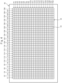
- the touch panel 14 has a plurality of transparent sensor electrodes arranged in a matrix.
- the sensor electrodes are, for example, formed by ITO (indium tin oxide) or another transparent electroconductive material.
- the touch panel 14 has drive side sensor electrodes extending in the row direction, and reception side sensor electrodes extending in the column direction. These drive side sensor electrodes and reception side sensor electrodes are arranged in a lattice shape. Further, a pulse voltage is applied so that a weak electric field is generated between the drive side sensors electrode and the reception side sensor electrodes. If a human finger or other object approaches these sensor electrodes and an electrostatic capacity is formed between the sensor electrodes and the object, the electric field generated between the sensor electrodes is decreased and the charge at the reception side sensor electrodes is decreased along with this.
- the touch panel 14 outputs the distribution C(x,y) of the electrostatic capacity, but may also output the value of another parameter relating to the electrostatic capacity.
- the touch panel 14 may also output the distribution of the distribution R(x,y) of the current values detected at the sensor electrodes.
- the distribution C(x,y) of the electrostatic capacity is calculated from the distribution R(x,y) of the current values.
- the memory part 17 for example, has a volatile semiconductor memory (for example, RAM), nonvolatile semiconductor memory (for example, ROM), or the like. Furthermore, the memory part 17 may have a hard disk drive (HDD), solid state drive (SSD), or optical recording medium. Further, a part of the memory part 17 may be a detachable removable medium.
- the memory part 17 stores computer programs for performing various processing at the processor 18, various data used when various processing is performed by the processor 18, or the like.
- the computer programs include an OS program, application programs (for example, game programs), or the like.
- the processor 18 has one or more CPUs (central processing units) and their peripheral circuits.
- the processor 18 may further have a processing circuit such as a logical operation unit or numerical operation unit.
- the processor 18 performs various processing based on computer programs stored in the memory part 17.
- the processor 18 has an information processing part 181 performing processing based on operating information or the like at the touch panel 14 when a computer program (OS program or application program) is run, and an image output part 182 outputting image data of the image to be shown at the display part 13.
- the information processing part 181 receives operating information at the touch panel 14 from the analysis part 15. Further, the information processing part 181 may receive the operating information of the operating device 50 described below, from the communication interface 16. Further, the information processing part 181 takes out the necessary data from the memory part 17. The information processing part 181 performs processing in accordance with a computer program run based on the touch panel 14 or the operating information of the operating device 50 and the data stored in the memory part 17, or the like. As a result, the information processing part 181 generates image data to be displayed at the display part 13 and data to be stored in the memory part 17. Note that, the information processing part 181 may generate audio data, vibration data or the like, if the electronic apparatus 10 or the operating device 50 has other notification device such as a speaker, vibration generator or the like.
- the image output part 182 outputs image data generated by the information processing part 181 to the display part 13. Note that, the image output part 182 may also output image data to a separate monitor, for example, if the electronic apparatus 10 is connected to another monitor (not shown).
- the input device 20 inputs instructions to the electronic apparatus 10 through the touch screen 12 of the electronic apparatus 10 in accordance with an operation at an operating part of the input device 20 by the user if there is such an operation.
- the input device 20 has a board 30 having a plurality of operating parts 31 and sockets 40 having pluralities of electrodes 43.
- the sockets 40 are formed to be able to be detached from the board 30.
- the sockets 40 are attached to the board 30.
- the board 30 is formed line symmetrically up-down and left-right in FIG. 1 .
- the two sockets 40 have the same configurations. Therefore, the two sockets 40 can respectively be attached to both the left and right of the electronic apparatus 10 in FIG. 1 . Further, the electronic apparatus 10 can be attached in the reverse direction in the up-down direction in FIG. 1 with respect to the board 30.
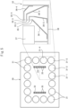
- FIG. 5 is a plan view showing the board 30 of the input device 20.
- FIG. 5 shows a plan view of the board 30 in the state where the sockets 40 are detached and shows the configuration of an electroconductive member 32 buried in the board 30, regarding a partial region of the board 30.
- the operating parts 31 are operated by the user and, for example, include buttons, switches, or the like.
- the operating parts 31 are formed as circular push buttons.
- the operating parts 31 may be buttons or switches having other shapes such as rectangular shape, oval shape, cross shape, or the like.
- the first operating part 31-1 to third operating part 31-3 and the 14 th operating part 31-14 to the 16 th operating part 31-16 are arranged along one side (first side) among the two long sides of the display screen of the touch screen 12.
- the sixth operating part 31-6 to the 11 th operating part 31-11 are arranged along the long side (second side) facing the first side of the display screen of the touch screen 12.
- the third operating part 31-3 to sixth operating part 31-6 are arranged along one side (third side) among the two short sides of the display screen of the touch screen 12.
- the 11 th operating part 31-11 to the 14 th operating part 31-14 are arranged along the short side (fourth side) facing the third side of the display screen of the touch screen 12.
- the operating parts 31 include the second set of operating parts (fourth operating part 31-4 and fifth operating part 31-5 and the 12 th operating part 31-12 and 13 th operating part 31-13) arranged so as to straddle the third side and fourth side of the display screen of the touch screen 12 when viewed in a direction perpendicular to the display screen at the time of attachment of the input device 20.
- the operating parts 31 being arranged so as to surround the four sides of the electronic apparatus 10 in this way, multiple users can surround the electronic apparatus 10 at its four sides and respectively operate the operating parts 31, and therefore new user experiences can be provided.
- the board side terminals 35 at the left side of the board 30 are connected through the terminal side wirings 36 to operating parts 31 arranged at the left side among the operating parts 31 arranged along the long sides of the display screen of the touch screen 12 (first side and second side) and to operating parts 31 arranged along the short side at the left side of the display screen of the touch screen 12 (the other of the third side and fourth side).
- the operating parts 31 are connected to the corresponding board side terminals 35 through the terminal side wirings 36 and are connected to the metal sheet 37 through the ground side wiring 38.
- the operating parts 31 are rendered a state where the terminal side wirings 36 connected to the operating parts 31, and the ground side wiring 38 are electrically disconnected when the operating parts 31 are not being pushed by the user.
- the operating parts 31 are rendered a state where the terminal side wirings 36 connected to the operating parts 31, and the ground side wiring 38 are electrically connected when the operating parts 31 are being pushed by the user.
- the potentials of the board side terminals 35 corresponding to the operating parts 31 change due to operation of the operating parts 31 by the user.
- the terminal-use openings 33 are openings provided at the first surface side of the board 30. Inside the terminal-use openings 33, a plurality of board side terminals 35 are arranged. Due to the terminal-use openings 33, the board side terminals 35 are exposed to the outside of the board 30. In the present embodiment, two terminal-use openings 33 are provided in the board 30. Inside each terminal-use opening 33, eight board side terminals 35 are arranged.
- the board 30 is formed to be able to be bent.
- the board 30, as shown in FIG. 1 is formed so as to be able to be folded into two at the folding line X.
- the folding line X extends through the center of the board 30, and therefore the operating parts 31 are arranged line symmetrically about the folding line X.
- the electroconductive member 32 may also be formed divided into two at both sides of the folding line.
- metal sheets 37 are respectively provided at the regions at both sides of the folding line and are connected to the operating parts 31 and board side terminals 35 arranged in the corresponding regions.
- the board 30 is formed as a rigid plate-shaped member.
- the board 30 may also, for example, be formed as a sheet-shaped member with flexibility.
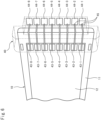
- FIG. 6 is a perspective view of a socket 40 and electronic apparatus 10 in the state where the socket 40 is attached to the electronic apparatus 10.
- the body of the socket 40 is shown in a transparent state by broken lines.
- a socket 40 is an example of a fastening part for fastening the input device 20 to the electronic apparatus 10 in a detachable manner.
- a socket 40 is formed by a nontransparent and nonconductive material.
- the socket 40 has a recessed part 42, a plurality of electrodes 43, a plurality of socket side terminals 44, and socket wirings 45 connected to the electrodes 43 and socket side terminals 44. Therefore, the socket 40 performs the two functions of fastening the input device 20 with respect to the electronic apparatus 10 while holding the electrodes 43. Due to this, the number of parts of the input device 20 becomes smaller due to this.
- a socket 40 is fastened to the board 30 in a detachable manner. Therefore, the input device 20 is fastened to the electronic apparatus 10 by the socket 40 being fastened to the board 30 in the state with the electronic apparatus 10 fit in the socket 40. Therefore, the socket 40 fastens the input device 20 to the electronic apparatus 10 in a detachable manner.
- the surface of the touch screen 12 where the plurality of electrodes 43 are arranged is covered by the nontransparent socket 40, when the socket 40 is attached to the electronic apparatus 10.
- the socket 40 functions as a nontransparent covering part covering the surface of the touch screen 12 where the plurality of electrodes 43 are arranged.
- the electrodes 43 being covered by the socket 40 in this way, the user can be prevented from touching the electrodes 43.
- the surface of the touch screen 12 where the electrodes 43 are arranged being covered by the socket 40, the user can concentrate more on the screen displayed at the touch screen 12 not covered by the socket 40.
- the socket 40 is formed by a nonconductive material, therefore by the electrodes 43 being covered by the socket 40, the electrostatic capacity between an electrode 43 and the touch panel 14 is kept from changing due to the hand of the user or other external factor.
- one socket 40 is provided with eight electrodes 43 of the first electrode 43-1 to the eighth electrode 43-8.
- the number of electrodes 43 is equal to the number of board side electrodes 35 arranged inside one terminal-use opening 33.
- the plurality of electrodes 43 are connected to the respective socket side terminals 44 through the socket wirings 45.
- a socket 40 is provided with eight socket side terminals 44 from the first socket side terminal 44-1 to the eighth socket side terminal 44-8.
- the socket side terminals 44 are electrically connected to the corresponding board side terminals 35 of the board 30 when the socket 40 is fastened to the board 30.
- the first socket side terminal 44-1 is connected to the first board side terminal 35-1.
- the first electrode 43-1 is connected to the first operating part 31-1 and accordingly can be connected with the metal sheet 37 through the first operating part 31-1.
- the metal sheet 37 is formed to be able to connect with a plurality of electrodes 43 in accordance with the operation of the operating part 31.
- the plurality of electrodes 43 arranged aligned along the short side at the left side of the display screen of the touch screen 12 are connected to the operating parts 31 arranged at the left side among the operating parts 31 arranged along the long sides of the display screen of the touch screen 12 (first side and second side) and the operating parts 31 arranged along the short side at the left side of the display screen of the touch screen 12 (the other of the third side and fourth side).
- the potential of the electrode 43 corresponding to the operating part 31 changes.
- the electrodes 43 are connected to the operating parts 31 so that their potentials change in accordance with the states of operation of the operating parts 31 corresponding to the electrodes 43.
- the potential of the electrode 43 corresponding to the operating part 31 becomes a potential substantially the same as the ground electrode of the electronic apparatus 10. If the potential of an electrode 43 changes in this way, the electrostatic capacity between the electrode 43 and the region on the touch panel 14 corresponding to the electrode 43 changes. The change in the electrostatic capacity is detected by a sensor electrode of the touch panel 14.
- the potential of the first electrode 43-1 connected to the first operating part 31-1 through the first terminal side wiring 36-1, first board side terminal 35-1, first socket side terminal 44-1, and socket wiring 45 changes.
- the potential of the first electrode 43-1 changes, at the region of the touch panel 14 corresponding to the first electrode 43-1, specifically, for example, the four sections positioned at the intersections of the R21 row, R22 row and the C37 column, C38 column, the electrostatic capacity between the first electrode 43-1 and these sections changes and the change in the electrostatic capacity is detected by the sensor electrodes corresponding to these sections. Therefore, in the present embodiment, an operation at the operating part 13 by the user can be detected by the touch panel 14.
- An operating device 50 is a device for a user to input operating information to the electronic apparatus 10.
- the operating device 50 is a controller having push buttons, a cross button, a joystick, or the like.
- the operating device 50 sends operating information of these buttons and joystick operated by the user to the electronic apparatus 10.
- the operating device 50 is formed to be able to be attached to the electronic apparatus 10.
- operating devices 50 as shown in FIG. 7A , are attached to side parts of the electronic apparatus 10 at the short sides of the touch screen 12. If the operating device 50 is attached to the electronic apparatus 10 in this way, the electronic apparatus 10 communicates with the operating device 50 though the communication interface 16 by wire.
- the operating device 50 is formed to be able to be detached from the electronic apparatus 10. If the operating device 50 is detached from the electronic apparatus 10 in this way, the electronic apparatus 10 communicates with the operating device 50 through the communication interface 16 wirelessly. In either case, operating information of the operating device 50 is input to the processor 18 through the communication interface 16 of the electronic apparatus 10. In this case, the information processing part 181 runs processing at an OS program or application program based on the operating information input from the operating device 50.
- the input device 20 can be attached to the electronic apparatus 10.
- the input device 20 is also attached to side parts of the electronic apparatus 10 at short sides of the touch screen 12, and therefore the input device 20 (in particular, the sockets 40) is attached to the attachment positions of the operating devices 50 when the operating devices 50 are detached from the electronic apparatus 10.
- the operating devices 50 can communicate with the electronic apparatus 10 wirelessly and accordingly operating information at the operating devices 50 is input to the processor 18 through the communication interface 16 of the electronic apparatus 10.
- the operating parts 31 are arranged to surround the four sides of the electronic apparatus 10 when viewed in the direction perpendicular to the display surface at the time of attachment of the input device 20. However, as long as they are arranged to surround at least three sides, they may not be arranged to surround four sides. In this case as well, it is possible for a plurality of users to surround the electronic apparatus 10 at three sides to respectively operate the operating parts 31 and accordingly possible to provide a new user experience. Note that, the operating parts 31 may also be arranged at only one side or two sides of the electronic apparatus 10.
- the same number of operating parts 31 are arranged at the outside of each of the long sides of the display screen, and the same number of operating parts 31 are arranged at the outside of each of the short sides of the display screen.
- the number of the operating parts 31 arranged at the outside of each of the long sides or short sides does not necessarily have to be the same.
- the electronic apparatus 10 when the input device 20 is attached to the electronic apparatus 10, the electronic apparatus 10 is placed on the board 30 of the input device 20.
- the electronic apparatus 10 it is also possible to provide an opening part at the center of the board 30 and to insert the electronic apparatus 10 in the opening part when the input device 20 is attached to the electronic apparatus 10.
- the plurality of electrodes 43 are arranged along the short sides of the display screen of the touch screen 12. However, a part or all of the plurality of electrodes 43 may also be arranged along the long sides of the display screen of the touch screen 12. In particular, if the socket 40 is attached to the electronic apparatus 10 at the long side of the touch screen 12, the plurality of electrodes 43 may also be arranged along the long side at the side where the socket 40 is attached.
- the socket 40 functions as a fastening part for fastening the input device 20 to the electronic apparatus 10 in a detachable manner and a covering part for covering the surface of the touch screen 12 where the electrodes 43 are arranged.
- the socket 40 may also function as only one of these.
- a member separate from the socket 40 may also be provided as the covering part.
- the electrodes 43 are not arranged at the socket 40 and the electrodes 43 are arranged at the separate member provided as the covering part.
- the operating part 31 is a member for connecting and disconnecting corresponding terminal-side wiring 36 and ground-side wiring 38 by user operation.
- the operating part 31 may also be any member as long as the potential of the electrode 43 connected to the operating part 31 changes in accordance with the state of operation of the operating part 31 by a user.
- the operating part 31 may be electrode plate connected to the corresponding electrode 43. In this case, if a user touches the electrode plate, the potential of the electrode 43 corresponding to the electrode plate is connected to the body of the user and becomes a ground potential, and thereby potential of the electrode 43 changes. Further, in this case, since the potential of the electrode 43 does not have to be made to match the potential of the ground electrode of the electronic apparatus 10, the board 30 does not have to be provided with the metal plate 37 and ground-side wiring 38.
- the input device 20 has the board 30 having the operating parts 31, and the sockets 40 having the electrodes 43.
- the input device 20 may have an integral member having the operating parts 31 and electrodes 43 instead of the board 30 and sockets 40.
- a member for example, a sheet-shaped member having a plurality of operating parts 31 configured as electrodes which a user would contact, and a plurality of electrodes 43 electrically connected with these plurality of operating parts 31 would be conceivable.
- FIG. 8 is a plan view schematically showing the electronic apparatus set 1 according to the second embodiment.
- FIG. 9 is a schematic partial cross-sectional side view of a part of the electronic apparatus set 1 seen along the line IX-IX of FIG. 8 .
- the electronic apparatus set 1 has an electronic apparatus 10 according to the first embodiment, and four input devices 20' able to be attached to the electronic apparatus 10.
- the electronic apparatus 10 is configured in the same way as the electronic apparatus according to the first embodiment. Further, the electronic apparatus 10, in the same way as the electronic apparatus according to the first embodiment, may be configured to enable operating devices 50 to be attached to the side parts of the electronic apparatus 10 at the short sides of the touch screen 12.
- An input device 20' performs input to the electronic apparatus 10 through the touch screen 12 of the electronic apparatus 10 in accordance with operation of the operating parts 71 of the input device 20' by the user when such an operation is performed.
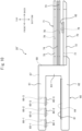
- Each input device 20' has a clip part 60 having a plurality of apparatus-side electrodes 80, and a plate-shaped part 70 having a plurality of operating parts 71.
- FIG. 8 describes directions when the input device 20' at the bottom left of the figure is used as a reference.
- the electronic apparatus 10 and input devices 20' do not necessarily have to be used with the touch screen 12 facing vertically upward. For example, they may also be used so that the touch screen 12 faces the horizontal direction.
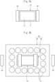
- FIG. 10 is a disassembled side view of an input device 20'
- FIG. 11 is a plan view of the input device 20'.
- the inside structures are shown by broken lines.
- the clip part 60 has an elastic member-use groove 64, electrode-use grooves 65, wiring-use through holes 66, wiring-use upper grooves 67, and wiring-use side grooves 68.
- These elastic member-use groove 64, electrode-use grooves 65, wiring-use through holes 66, wiring-use upper grooves 67, and wiring-use side grooves 68 are formed at the top member 61, bottom member 62, or intermediate member 63.
- the elastic member 81 is, for example, formed by a material having elasticity and high in friction coefficient such as urethane.
- the elastic member 81 is configured so that its top surface sticks out slightly upward from the top surface of the bottom member 62. In particular, in the present embodiment, it is configured so that the interval between the top surface of the elastic member 81 and the bottom surfaces of the later explained apparatus-side electrodes 80 becomes slightly smaller than the thickness of the electronic apparatus 10.
- the electrode-use grooves 65 and apparatus-side electrodes 80 are formed to become rectangular when viewed from above.
- the electrode-use grooves 65 are formed to become slightly broader than the apparatus-side electrodes 80 when viewed from above so as to enable them to hold the upper parts of the apparatus-side electrodes 80.
- the electrode-use grooves 65 and apparatus-side electrodes 80 may have shapes other than rectangular ones as long as having shapes complementary with each other so as to enable the lower parts of the apparatus-side electrodes 80 to be held inside the electrode-use grooves 65.
- the apparatus-side electrodes 80 are for example formed by a material having elasticity and having electroconductivity such as electroconductive rubber.
- the apparatus-side electrodes 80 are formed so that their bottom surfaces stick out slightly downward from the bottom surface of the top member 61.
- the input device 20' attached to the electronic apparatus 10 is kept from detaching.
- the apparatus-side electrodes 80 closely contact the touch panel 14 of the electronic apparatus 10, as explained later, a change in the electrostatic capacity generated as a result of operation by the user at the operating part 71 can be suitably transmitted to the touch panel 14.
- the wiring-use upper groove 67 and the wiring-use side groove 68 are respectively formed at the top surface of the top member 61 and the back surface of the intermediate member 63.
- the wiring-use upper groove 67 and the wiring-use side groove 68 are respectively formed by the width and depth that enables them to hold a wiring.
- the wiring-use upper groove 67 extend in the front-back direction, while the wiring-use side groove 68 extend in the top-bottom direction.
- Each wiring-use upper groove 67 is communicated with the corresponding wiring-use through holes 66 and corresponding wiring-use side groove 68 and extends between them.
- the wiring-use upper groove 67 extends from the corresponding wiring-use through holes 66 to the back end of the top member 61.
- each wiring-use side groove 68 is communicated with the corresponding wiring-use upper groove 67 and corresponding wiring-use groove 77 (explained later) and extends between them.
- the wiring-use side groove 68 extend in the top-bottom direction from the top end of the top member 61 to the wiring-use groove 77.
- the first wiring-use upper groove 67-1 communicating with the first wiring-use through hole 66-1 and the first wiring-use side groove 68-1, as shown in FIG. 11 is positioned at the center among three wiring-use upper grooves 67, while the remaining second wiring-use upper groove 67-2 and third wiring-use upper groove 67-3 are positioned at its both sides.
- three apparatus-side electrodes 80 are provided at the top member 61.
- one, two, or four or more apparatus-side electrodes 80 may also be provided at the top member 61.
- the same numbers of electrode-use grooves 65, wiring-use through holes 66, wiring-use upper grooves 67, and the wiring-use side grooves 68 as the number of apparatus-side electrodes 80 are formed.
- the plate-shaped part 70 is formed from a plurality of layers.
- FIG. 10 shows the plurality of layers separated.
- the plate-shaped part 70 has a base member 72, frame member 73, insulating member 74, and surface layer member 75 formed in layers.
- the base member 72, frame member 73, insulating member 74, and surface layer member 75 all have the same sizes in the front-back direction and transverse direction.
- the base member 72 is formed by a nonconductive material. Further, the base member 72 is formed integrally with the clip part 60 by the same material as the clip part 60. The clip part 60 and the base member 72 are for example formed integrally by injection molding or the like.
- the base member 72 has electrode-use grooves 76 and wiring-use grooves 77 at its top surface.
- the same number of electrode-use grooves 76 as the number of apparatus-side electrodes 80 provided at the clip part 60 are provided at the base member 72. Therefore, in the present embodiment, three electrode-use grooves 76 are formed at the base member 72. These three electrode-use grooves 76 are arranged aligned in the transverse direction. In the present embodiment, as shown in FIG.
- the first electrode-use groove 76-1 is arranged at the center
- the second electrode-use groove 76-2 is arranged at one side of the first electrode-use groove 76-1 in the transverse direction
- the third electrode-use groove 76-3 is arranged at the other side of the first electrode-use groove 76-1 in the transverse direction.
- operating-side electrodes 82 are arranged at the electrode-use grooves 76. Specifically, the first operating-side electrode 82-1 is arranged at the first electrode-use groove 76-1, the second operating-side electrode 82-2 is arranged at the second electrode-use groove 76-2, and the third operating-side electrode 82-3 is arranged at the third electrode-use groove 76-3.
- the electrode-use groove 76 and the operating-side electrode 82 are formed so as to become rectangular when viewed from above.
- the electrode-use groove 76 is formed to become just slightly broader than the operating-side electrode 82 when viewed from above so as to enable it to hold the lower part of the operating-side electrode 82.
- the operating-side electrode 82 is formed so that the length of its short sides becomes larger than the width of the contact part of a finger when a finger of a person of a general size pushes the operating part 71. Due to this, the change in electrostatic capacity detected at the touch panel 14 when the operating part 71 is operated by a finger of a user can be made as large as possible.
- the operating-side electrodes 82 are formed by a material having electroconductivity, for example, a metal such as copper.
- the operating-side electrode 82 are formed so that its top surface sticks out slightly upward from the top surface of the base member 72.
- the operating-side electrode 82 may also be formed for example by any other material such as an electroconductive rubber as long as the material has electroconductivity.
- the first wiring-use groove 77-1 is communicated with the first wiring-use side groove 68-1 and the first electrode-use groove 76-1
- the second wiring-use groove 77-2 is communicated with the second wiring-use side groove 68-2 and the second electrode-use groove 76-2
- the third wiring-use groove 77-3 is communicate with the third wiring-use side groove 68-3 and the third electrode-use groove 76-3.
- the frame member 73 is formed by a nonconductive material.
- the frame member 73 is formed by the same material as the base member 72.
- the frame member 73 has a rectangular shaped opening 78 of substantially the same shape as the operating-side electrode 82 and just slightly larger than the operating-side electrode 82, at the same positions as the operating-side electrode 82 when viewed from above. Further, the frame member 73 has a height substantially the same as or just slightly higher than the height by which the top surface of the operating-side electrode 82 sticks out from the top surface of the base member 72.
- the insulating member 74 is arranged on the operating-side electrodes 82. For this reason, a finger of a user or the like will not directly touch the operating-side electrodes 82 and accordingly, if the operating-side electrodes 82 are formed by a metal such as copper, the operating-side electrodes 82 are kept from corroding.
- each operating-side electrode 82 forms an operating part 71 together with the insulating member 74 arranged on the operating-side electrode 82.
- the surface layer opening 79 may also be smaller than the operating-side electrode 82 and have a shape other than rectangular one as long as a finger of a user can contact the insulating member 74.
- the surface layer member 75 being provided with the surface layer openings 79 in this way, the regions near the regions where the operating-side electrodes 82 are provided become recessed from the surface of the surface layer member 75 and a finger of a user becomes easier to guide to the regions near the operating-side electrodes 82.
- the surface layer member 75 is for example fastened to the base member 72 by a fastener such as a screw (not shown). Due to this, the frame member 73 and insulating member 74 positioned between the surface layer member 75 and the base member 72 are also fastened to the base member 72, in addition to the surface layer member 75. Further, if using a detachable fastener as this fastener, the surface layer member 75 can be detached from the base member 72 and accordingly can be exchanged with an insulating member 74 having a different design. Note that, the base member 72, frame member 73, insulating member 74, and surface layer member 75 may also be adhered together by an adhesive at least at partially adjoining members.
- the apparatus-side electrodes 80 and the corresponding operating-side electrodes 82 are connected by corresponding wirings 83 (in FIGS. 10 and 11 , to facilitate understanding of the drawings, the wirings 83 are omitted).
- the first apparatus-side electrode 80-1 is connected to the first operating-side electrode 82-1 by the first wiring 83-1
- the second apparatus-side electrode 80-2 is connected to the second operating-side electrode 82-2 by the second wiring 83-2
- the third apparatus-side electrode 80-3 is connected to the third operating-side electrode 82-3 by the third wiring 83-3.
- Each wiring 83 extends passing through the corresponding wiring-use through hole 66, wiring-use upper groove 67, wiring-use side groove 68, and wiring-use groove 77.
- the first wiring 83-1 extends passing through the first wiring-use through hole 66-1, the first wiring-use upper groove 67-1, the first wiring-use side groove 68-1, and the first wiring-use groove 77-1.
- each of the clip parts 60 is configured so that the length L of the top member 61 and bottom member 62 in the front-back direction (see FIG. 9 ) become less than or equal to half of the length of the short side of the electronic apparatus 10.
- each of the clip parts 60 is configured so that the length of the top member 61 and bottom member 62 in the front-back direction becomes 1/2 to 1/4 or 1/2 to 1/3 of the length of the short side of the electronic apparatus 10.
- each of the input devices 20' of the present embodiment is formed into T-shape so that the plate-shaped part 70 extends perpendicular to the clip part 60. For this reason, the operating parts 71 of the plate-shaped part 70 become arranged along the long side of the electronic apparatus 10, and therefore a user can operate the operating parts 71 without moving away from the display screen of the touch screen 12 of the electronic apparatus 10.
- the electrostatic capacity detected by the sensor electrode of the touch panel 14 facing the apparatus-side electrode 80 corresponding to the operating part 71 will change. Specifically, for example, if a finger of a user approaches the first operating-side electrode 82-1 of the operating part 71, the potential of the first apparatus-side electrode 80-1 connected through the first wiring 83-1 to the first operating-side electrode 82-1 changes. If the potential of the first apparatus-side electrode 80-1 changes, at the region of the touch panel 14 corresponding to the first apparatus-side electrode 80-1, the electrostatic capacity between them changes. This change in electrostatic capacity is detected by the sensor electrode corresponding to that region. Therefore, in the present embodiment, operation of operating parts 71 by a user can be detected by the touch panel 14.
- the electronic apparatus 10 may also be configured so as to perform calibration when it is placed on a placement surface after the input devices 20' is attached thereto.
- the processor 18 of the electronic apparatus 10 judges that the input device 20' is attached, for example, if a total sum of electrostatic capacities detected at regions of the touch panel 14 facing apparatus-side electrodes 80 of the clip parts 60 when the input device 20' are attached becomes greater than or equal to a predetermined threshold value.
- the electronic apparatus 10 has an acceleration sensor or gyro sensor (not shown) connected to the processor 18, and the processor 18 judges whether the electronic apparatus 10 is being held in a horizontal state based on the output of the acceleration sensor or gyro sensor when judging that the input devices 20' have been attached.
- the processor 18 judges that the electronic apparatus 10 has been placed on a placement surface. At this time, the processor 18 performs calibration to make the electrostatic capacity detected by the sensor electrodes of the touch panel 14 the electrostatic capacity when no operation is being performed by the user. Due to attachment of the input devices 20', the electrostatic capacity detected by the sensor electrodes of the touch panel 14 will change somewhat, but by performing such calibration, even if there is such a change in the electrostatic capacity, it becomes possible to suitably detect operation of operating parts 71 by a user.
Landscapes
- Engineering & Computer Science (AREA)
- General Engineering & Computer Science (AREA)
- Theoretical Computer Science (AREA)
- Human Computer Interaction (AREA)
- Physics & Mathematics (AREA)
- General Physics & Mathematics (AREA)
- Multimedia (AREA)
- Position Input By Displaying (AREA)
Applications Claiming Priority (2)
| Application Number | Priority Date | Filing Date | Title |
|---|---|---|---|
| PCT/JP2022/021640 WO2023228383A1 (ja) | 2022-05-26 | 2022-05-26 | 入力装置及び電子機器セット |
| PCT/JP2023/018970 WO2023228907A1 (ja) | 2022-05-26 | 2023-05-22 | 入力装置及び電子機器セット |
Publications (2)
| Publication Number | Publication Date |
|---|---|
| EP4535136A1 true EP4535136A1 (de) | 2025-04-09 |
| EP4535136A4 EP4535136A4 (de) | 2026-06-24 |
Family
ID=88918850
Family Applications (1)
| Application Number | Title | Priority Date | Filing Date |
|---|---|---|---|
| EP23811779.0A Pending EP4535136A4 (de) | 2022-05-26 | 2023-05-22 | Eingabevorrichtung und elektronisches geräteset |
Country Status (3)
| Country | Link |
|---|---|
| US (1) | US20250085820A1 (de) |
| EP (1) | EP4535136A4 (de) |
| WO (2) | WO2023228383A1 (de) |
Family Cites Families (13)
| Publication number | Priority date | Publication date | Assignee | Title |
|---|---|---|---|---|
| JP4203476B2 (ja) * | 2005-01-24 | 2009-01-07 | シャープ株式会社 | 携帯情報装置 |
| DE102008041649A1 (de) * | 2008-08-28 | 2010-03-04 | Visteon Global Technologies, Inc., Van Buren Township | Bildschirmbasiertes Fahrzeugbediensystem |
| US8939838B2 (en) * | 2008-09-30 | 2015-01-27 | Apple Inc. | Accessory for playing games with a portable electronic device |
| US8686959B2 (en) * | 2010-02-16 | 2014-04-01 | Maurice Payne | Touch screen multi-control emulator |
| EP2670497A2 (de) * | 2011-01-31 | 2013-12-11 | Studio Sophisti V.O.F. | Brettspiel |
| WO2012117046A1 (de) * | 2011-03-01 | 2012-09-07 | Printechnologics Gmbh | Eingabeelement zur bedienung eines berührungsbildschirms |
| US8512151B1 (en) * | 2012-03-13 | 2013-08-20 | Disney Enterprises, Inc. | Integration of board games and touch screen devices |
| US20140247246A1 (en) * | 2012-11-15 | 2014-09-04 | Daryl D Maus | Tactile to touch input device |
| JP2015075796A (ja) * | 2013-10-06 | 2015-04-20 | 信行 千葉 | 入力デバイス |
| US9207827B1 (en) * | 2014-10-14 | 2015-12-08 | Disney Enterprises, Inc. | Multi-touch surface extension using conductive traces and pads |
| JP6635597B2 (ja) * | 2015-06-12 | 2020-01-29 | 任天堂株式会社 | 情報処理システム、および、操作装置 |
| US10228804B2 (en) * | 2015-07-09 | 2019-03-12 | Kyocera Corporation | Mobile device with periodic estimation of underwater state based on detected acceleration |
| GB2620789A (en) * | 2022-07-22 | 2024-01-24 | Sony Interactive Entertainment Inc | An entertainment system, a method and a computer program |
-
2022
- 2022-05-26 WO PCT/JP2022/021640 patent/WO2023228383A1/ja not_active Ceased
-
2023
- 2023-05-22 WO PCT/JP2023/018970 patent/WO2023228907A1/ja not_active Ceased
- 2023-05-22 EP EP23811779.0A patent/EP4535136A4/de active Pending
-
2024
- 2024-11-26 US US18/960,558 patent/US20250085820A1/en active Pending
Also Published As
| Publication number | Publication date |
|---|---|
| WO2023228907A1 (ja) | 2023-11-30 |
| EP4535136A4 (de) | 2026-06-24 |
| WO2023228383A1 (ja) | 2023-11-30 |
| JPWO2023228907A1 (de) | 2023-11-30 |
| US20250085820A1 (en) | 2025-03-13 |
Similar Documents
| Publication | Publication Date | Title |
|---|---|---|
| US9383821B2 (en) | Method for presenting tactile sensation and device therefor | |
| US8508492B2 (en) | Touch panel and method of detecting press operation position thereon | |
| EP2759913A2 (de) | In einer Berührungsbildschirmtafel integrierte Anzeigevorrichtung | |
| KR102081606B1 (ko) | 터치 ic 및 이를 이용한 터치 스크린 일체형 표시장치 | |
| AU2017208277B2 (en) | Back of cover touch sensors | |
| CN100559339C (zh) | 输入装置和使用该输入装置的电子设备 | |
| EP3044654B1 (de) | Kapazitiver sensor zur erkennung von berührungspositionen und presskräften | |
| KR101768052B1 (ko) | 터치 스크린 패널 및 그의 구동방법 | |
| US8711113B2 (en) | Modular connector for touch sensitive device | |
| JP5871307B2 (ja) | 位置検出センサユニットおよび位置検出装置 | |
| EP2750004A2 (de) | Berührungserkennungsvorrichtung, Anzeigevorrichtung mit Berührungserkennungsvorrichtung und elektronische Vorrichtung | |
| US20110069026A1 (en) | Touch panel module for providing electrically-stimulated sensation feedback | |
| JP2018063666A (ja) | 表示ドライバ、表示装置及び表示パネル | |
| JPH05265630A (ja) | 二次元入力装置における三次元データを得る方法及びコンピュータ装置 | |
| CN107728849B (zh) | 一种显示面板和显示装置 | |
| WO2021062433A1 (en) | Techniques for routing signals using inactive sensor regions of touch sensors and related systems and devices | |
| US20250085820A1 (en) | Input device and electronic apparatus set | |
| US11726609B2 (en) | Touch-sensitive apparatus and method | |
| EP4535138A1 (de) | Elektronisches instrument und elektronischer instrumentensatz | |
| US9746968B1 (en) | Touch screen display with tactile feedback using transparent actuator assemblies | |
| US20100182266A1 (en) | Touch panel and method of detecting press operation position thereon | |
| KR102177901B1 (ko) | 터치 스크린 일체형 표시장치 | |
| KR20140130923A (ko) | 터치 패널 | |
| JP2009136503A (ja) | ゲーム機の入力装置 | |
| JP2011180327A (ja) | 電気泳動表示装置、電子機器および電気泳動表示装置の駆動方法 |
Legal Events
| Date | Code | Title | Description |
|---|---|---|---|
| STAA | Information on the status of an ep patent application or granted ep patent |
Free format text: STATUS: THE INTERNATIONAL PUBLICATION HAS BEEN MADE |
|
| PUAI | Public reference made under article 153(3) epc to a published international application that has entered the european phase |
Free format text: ORIGINAL CODE: 0009012 |
|
| STAA | Information on the status of an ep patent application or granted ep patent |
Free format text: STATUS: REQUEST FOR EXAMINATION WAS MADE |
|
| 17P | Request for examination filed |
Effective date: 20241126 |
|
| AK | Designated contracting states |
Kind code of ref document: A1 Designated state(s): AL AT BE BG CH CY CZ DE DK EE ES FI FR GB GR HR HU IE IS IT LI LT LU LV MC ME MK MT NL NO PL PT RO RS SE SI SK SM TR |
|
| DAV | Request for validation of the european patent (deleted) | ||
| DAX | Request for extension of the european patent (deleted) | ||
| A4 | Supplementary search report drawn up and despatched |
Effective date: 20260527 |
|
| RIC1 | Information provided on ipc code assigned before grant |
Ipc: G06F 3/0354 20130101AFI20260520BHEP Ipc: A63F 13/2145 20140101ALI20260520BHEP Ipc: A63F 13/24 20140101ALI20260520BHEP Ipc: G06F 3/02 20060101ALI20260520BHEP Ipc: G06F 3/039 20130101ALI20260520BHEP Ipc: G06F 3/044 20060101ALI20260520BHEP |