EP4534239A1 - Klemmvorrichtung - Google Patents
Klemmvorrichtung Download PDFInfo
- Publication number
- EP4534239A1 EP4534239A1 EP23871635.1A EP23871635A EP4534239A1 EP 4534239 A1 EP4534239 A1 EP 4534239A1 EP 23871635 A EP23871635 A EP 23871635A EP 4534239 A1 EP4534239 A1 EP 4534239A1
- Authority
- EP
- European Patent Office
- Prior art keywords
- clamping device
- output rod
- ball
- operational
- hole
- Prior art date
- Legal status (The legal status is an assumption and is not a legal conclusion. Google has not performed a legal analysis and makes no representation as to the accuracy of the status listed.)
- Pending
Links
Images


Classifications
-
- B—PERFORMING OPERATIONS; TRANSPORTING
- B23—MACHINE TOOLS; METAL-WORKING NOT OTHERWISE PROVIDED FOR
- B23Q—DETAILS, COMPONENTS, OR ACCESSORIES FOR MACHINE TOOLS, e.g. ARRANGEMENTS FOR COPYING OR CONTROLLING; MACHINE TOOLS IN GENERAL CHARACTERISED BY THE CONSTRUCTION OF PARTICULAR DETAILS OR COMPONENTS; COMBINATIONS OR ASSOCIATIONS OF METAL-WORKING MACHINES, NOT DIRECTED TO A PARTICULAR RESULT
- B23Q1/00—Members which are comprised in the general build-up of a form of machine, particularly relatively large fixed members
- B23Q1/0063—Connecting non-slidable parts of machine tools to each other
- B23Q1/0072—Connecting non-slidable parts of machine tools to each other using a clamping opening for receiving an insertion bolt or nipple
-
- B—PERFORMING OPERATIONS; TRANSPORTING
- B23—MACHINE TOOLS; METAL-WORKING NOT OTHERWISE PROVIDED FOR
- B23Q—DETAILS, COMPONENTS, OR ACCESSORIES FOR MACHINE TOOLS, e.g. ARRANGEMENTS FOR COPYING OR CONTROLLING; MACHINE TOOLS IN GENERAL CHARACTERISED BY THE CONSTRUCTION OF PARTICULAR DETAILS OR COMPONENTS; COMBINATIONS OR ASSOCIATIONS OF METAL-WORKING MACHINES, NOT DIRECTED TO A PARTICULAR RESULT
- B23Q1/00—Members which are comprised in the general build-up of a form of machine, particularly relatively large fixed members
- B23Q1/0063—Connecting non-slidable parts of machine tools to each other
- B23Q1/0081—Connecting non-slidable parts of machine tools to each other using an expanding clamping member insertable in a receiving hole
-
- B—PERFORMING OPERATIONS; TRANSPORTING
- B23—MACHINE TOOLS; METAL-WORKING NOT OTHERWISE PROVIDED FOR
- B23Q—DETAILS, COMPONENTS, OR ACCESSORIES FOR MACHINE TOOLS, e.g. ARRANGEMENTS FOR COPYING OR CONTROLLING; MACHINE TOOLS IN GENERAL CHARACTERISED BY THE CONSTRUCTION OF PARTICULAR DETAILS OR COMPONENTS; COMBINATIONS OR ASSOCIATIONS OF METAL-WORKING MACHINES, NOT DIRECTED TO A PARTICULAR RESULT
- B23Q3/00—Devices holding, supporting, or positioning work or tools, of a kind normally removable from the machine
- B23Q3/02—Devices holding, supporting, or positioning work or tools, of a kind normally removable from the machine for mounting on a work-table, tool-slide, or analogous part
- B23Q3/06—Work-clamping means
- B23Q3/062—Work-clamping means adapted for holding workpieces having a special form or being made from a special material
-
- B—PERFORMING OPERATIONS; TRANSPORTING
- B25—HAND TOOLS; PORTABLE POWER-DRIVEN TOOLS; MANIPULATORS
- B25B—TOOLS OR BENCH DEVICES NOT OTHERWISE PROVIDED FOR, FOR FASTENING, CONNECTING, DISENGAGING OR HOLDING
- B25B5/00—Clamps
- B25B5/02—Clamps with sliding jaws
-
- B—PERFORMING OPERATIONS; TRANSPORTING
- B25—HAND TOOLS; PORTABLE POWER-DRIVEN TOOLS; MANIPULATORS
- B25J—MANIPULATORS; CHAMBERS PROVIDED WITH MANIPULATION DEVICES
- B25J15/00—Gripping heads and other end effectors
- B25J15/04—Gripping heads and other end effectors with provision for the remote detachment or exchange of the head or parts thereof
- B25J15/0408—Connections means
- B25J15/0416—Connections means having balls
Definitions
- the present invention relates to a clamping device which is suitable for detachably attaching a clamping object such as a work pallet, a work, a mold, a tool, or a jig to a base such as a clamping pallet, a table, or a robotic arm.
- a clamping object such as a work pallet, a work, a mold, a tool, or a jig
- a base such as a clamping pallet, a table, or a robotic arm.
- An object of the present invention is to provide a clamping device which can be driven without requiring compressed fluid such as compressed air or can be driven even if the compressed fluid is not supplied each time the clamping device is driven.
- This arrangement makes it possible to prevent the ball bodies from dropping from between the bottom surface of the recess and the operational member. Furthermore, the protrusion prevents the operational member from dropping due to the gravity.
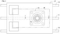
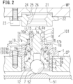
- FIG. 2 and FIG. 3 show First Embodiment of the present invention.
- the following will describe the structure of the clamping device 101 of First Embodiment. It is noted that FIG. 2 shows a released state of the clamping device 101 and is a cross section cut along a line X-X in FIG. 1 .
- a housing 1 of the clamping device 101 is fixed by means of bolts 2. From the housing 1, a cylindrical plug member 3 which is integrated with the housing 1 protrudes upward. Into a plug member cylindrical hole 3a of the plug member 3, an upper rod part 4a of an output rod 4 is inserted to be movable in an up-down direction (axial direction of the plug member cylindrical hole 3a). The axial direction of the output rod 4 is identical with the axial direction of the plug member cylindrical hole 3a.
- the fitting hole 24 is formed in the ring member 22, the fitting hole 24 may be formed by the inner circumference of the recess 21 of the work pallet WP.
- the engaging portion 25 and the tapered inner circumferential surface 26 described above may be formed directly in the inner circumference of the recess 21 of the work pallet WP.
- the above-described clamping device 101 operates as follows.
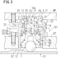
- the ball 7 is pressed upward by the cam portion 52 of the cam member 51, i.e., by an external force, and hence the ball 7 is pressed into the cylindrical hole 5 of the housing 1 as compared to the locked state shown in FIG. 3 . Due to this, a state in which the ball 7 presses the output rod 4 upward (i.e., toward the leading end side) against the biasing force of the spring 9 and the output rod 4 ascends has been established. As the output rod 4 has ascended, the ball 14 of the plug member 3 is movable to the retracting position inside the retracting groove 16. To a space above the clamping device 101 in the released state shown in FIG. 2 , the work pallet WP is transported.
- the work pallet WP When the work pallet WP is clamped by the clamping pallet CP, to begin with, the work pallet WP is descended and the plug member 3 is inserted into the fitting hole 24 of the ring member 22. At this stage, the tapered inner circumferential surface 26 of the fitting hole 24 is in contact with the tapered outer circumferential surface 17a of the collet 17 in an enlarged diameter state, and a slight gap is formed between the upper surface 1a (seating surface) of the housing 1 and the lower surface of the ring member 22. Thereafter, as the clamping pallet CP is driven to run on the rails 50, the cam portion 52 of the cam member 51 is separated from the ball 7.
- the ball 7 when the clamping device is in the locked state, the ball 7 is not supported from below by the cam member 51. However, the ball 7 does not drop thanks to the above-described protrusion 27b.
- the ball 7 hits the cam portion 52 of the cam member 51 as the clamping pallet CP is driven to run on the rails 50, a lateral reaction force from the cam portion 52 is received by the housing 1 through the guide member 27 having the above-described sliding surface 27a. On this account, it is possible to suppress the lateral reaction force from being applied to the output rod 4 and to further smoothly move the output rod 4 toward the leading end side.
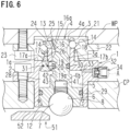
- FIG. 6 and FIG. 7 show Third Embodiment of the present invention.
- a clamping device of Third Embodiment includes a biasing member configured to press and move the output rod 4 downward (i.e., toward the base end side). This is the difference from the clamping device of First Embodiment.
- the clamping device of Third Embodiment is different from the clamping device of Second Embodiment in terms of means for preventing the ball 7 from dropping.
- the air filler 34 includes members such as a cylindrical main body portion 35, a ball 36, a spring 37, and a retaining cylinder 38.
- the main body portion 35 is hermetically fixed to the filling port 32 through a sealing member 39.
- the retaining cylinder 38 is hermetically fixed through an O-ring 40 by pressure.
- the ball 36 and the spring 37 are accommodated.
- an air filling tube (not illustrated) is connected to a female screw hole 35a of the main body portion 35. The inside of the air filling tube always receives the pressure of the compressed air.
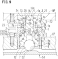
- a pressing portion 16a constituting part of the retracting groove 16 formed in the output rod 4 presses the ball 14 of the plug member 3 to a protruding position on the outer side in the radial direction, and then the ball 14 is engaged with the engaging portion 25. Consequently, the clamping device is switched from the released state shown in FIG. 8 to the locked state shown in FIG. 9 .
- the ball 7 (operational member) may be pressed and moved by the cam member 52 as the cam portion 51 is moved.
- means for generating the external force for moving the ball 7 (operational member) is not limited to a member such as the cam member 51.
Landscapes
- Engineering & Computer Science (AREA)
- Mechanical Engineering (AREA)
- Robotics (AREA)
- Jigs For Machine Tools (AREA)
Applications Claiming Priority (2)
| Application Number | Priority Date | Filing Date | Title |
|---|---|---|---|
| JP2022152081A JP2024046792A (ja) | 2022-09-26 | 2022-09-26 | クランプ装置 |
| PCT/JP2023/031045 WO2024070394A1 (ja) | 2022-09-26 | 2023-08-28 | クランプ装置 |
Publications (2)
| Publication Number | Publication Date |
|---|---|
| EP4534239A1 true EP4534239A1 (de) | 2025-04-09 |
| EP4534239A4 EP4534239A4 (de) | 2025-10-15 |
Family
ID=90477092
Family Applications (1)
| Application Number | Title | Priority Date | Filing Date |
|---|---|---|---|
| EP23871635.1A Pending EP4534239A4 (de) | 2022-09-26 | 2023-08-28 | Klemmvorrichtung |
Country Status (6)
| Country | Link |
|---|---|
| EP (1) | EP4534239A4 (de) |
| JP (1) | JP2024046792A (de) |
| KR (1) | KR20250044430A (de) |
| CN (1) | CN119866255A (de) |
| TW (1) | TWI877772B (de) |
| WO (1) | WO2024070394A1 (de) |
Families Citing this family (2)
| Publication number | Priority date | Publication date | Assignee | Title |
|---|---|---|---|---|
| TWI908348B (zh) * | 2024-09-21 | 2025-12-11 | 威光自動化科技股份有限公司 | 物件電性檢測治具及其操作方法 |
| TWI908694B (zh) * | 2024-09-21 | 2025-12-11 | 威光自動化科技股份有限公司 | 物件電性檢測治具及其操作方法 |
Family Cites Families (10)
| Publication number | Priority date | Publication date | Assignee | Title |
|---|---|---|---|---|
| EP0922529B1 (de) * | 1997-12-11 | 2002-11-06 | Parotec AG | Einheit zum lösbaren Verbinden von Teilen einer Palettiervorrichtung und Palettiervorrichtung |
| JP2001225236A (ja) * | 2000-02-14 | 2001-08-21 | Nabeya Iron & Tool Works Ltd | 締結装置 |
| CN101142053A (zh) * | 2005-03-18 | 2008-03-12 | 克斯美库股份有限公司 | 螺纹啮合型夹紧装置、夹紧系统及流体压力致动器 |
| WO2011046039A1 (ja) * | 2009-10-13 | 2011-04-21 | 株式会社コスメック | クランプ装置 |
| JP5474608B2 (ja) * | 2010-03-01 | 2014-04-16 | パスカルエンジニアリング株式会社 | クランプ装置 |
| JP5541786B2 (ja) * | 2010-05-10 | 2014-07-09 | パスカルエンジニアリング株式会社 | クランプ装置 |
| US9981391B2 (en) * | 2015-02-16 | 2018-05-29 | Norgren Automation Solutions, Llc | Quick disconnect apparatus for modular tooling |
| JP6353796B2 (ja) * | 2015-02-27 | 2018-07-04 | 株式会社コスメック | 出力装置および出力システム |
| JP6341186B2 (ja) * | 2015-11-24 | 2018-06-13 | マツダ株式会社 | ワーククランプ装置 |
| WO2021177385A1 (ja) | 2020-03-06 | 2021-09-10 | 株式会社コスメック | クランプ装置 |
-
2022
- 2022-09-26 JP JP2022152081A patent/JP2024046792A/ja active Pending
-
2023
- 2023-08-28 CN CN202380065399.9A patent/CN119866255A/zh active Pending
- 2023-08-28 KR KR1020257007130A patent/KR20250044430A/ko active Pending
- 2023-08-28 WO PCT/JP2023/031045 patent/WO2024070394A1/ja not_active Ceased
- 2023-08-28 EP EP23871635.1A patent/EP4534239A4/de active Pending
- 2023-09-07 TW TW112134068A patent/TWI877772B/zh active
Also Published As
| Publication number | Publication date |
|---|---|
| TWI877772B (zh) | 2025-03-21 |
| TW202421331A (zh) | 2024-06-01 |
| EP4534239A4 (de) | 2025-10-15 |
| WO2024070394A1 (ja) | 2024-04-04 |
| CN119866255A (zh) | 2025-04-22 |
| JP2024046792A (ja) | 2024-04-05 |
| KR20250044430A (ko) | 2025-03-31 |
Similar Documents
| Publication | Publication Date | Title |
|---|---|---|
| EP4534239A1 (de) | Klemmvorrichtung | |
| JP5690275B2 (ja) | クランプ装置 | |
| EP4545247A1 (de) | Vorrichtung zum ersetzen eines elements | |
| US12134157B2 (en) | Clamping apparatus | |
| US8523155B2 (en) | Fluid passage connection device | |
| KR102175508B1 (ko) | 클램프 장치 | |
| KR20010049813A (ko) | 데이텀기능을 부착한 클램프장치 | |
| EP1588794A1 (de) | Positionierungsvorrichtung | |
| KR100411829B1 (ko) | 워크 서포트 | |
| CN219925208U (zh) | 夹紧装置 | |
| EP3895840A1 (de) | Spannvorrichtung | |
| JP2017154246A (ja) | リフト機能付きクランプ装置 | |
| JP2003181730A (ja) | クランプ装置 | |
| US11572903B2 (en) | Pneumatic cylinder device with holding valve | |
| JP2015003346A (ja) | クランプ装置 | |
| CN217946223U (zh) | 非活性气体供给气缸 | |
| JP3239951U (ja) | クランプ装置 | |
| EP4603224A1 (de) | Positioniervorrichtung | |
| JP2026059675A (ja) | クランプ装置 | |
| JP2017100271A (ja) | クランプ装置 | |
| JP2023164116A (ja) | ロック装置 | |
| WO2023162801A1 (ja) | クランプ装置 | |
| JP2024062652A (ja) | クランプ装置 |
Legal Events
| Date | Code | Title | Description |
|---|---|---|---|
| STAA | Information on the status of an ep patent application or granted ep patent |
Free format text: STATUS: THE INTERNATIONAL PUBLICATION HAS BEEN MADE |
|
| PUAI | Public reference made under article 153(3) epc to a published international application that has entered the european phase |
Free format text: ORIGINAL CODE: 0009012 |
|
| STAA | Information on the status of an ep patent application or granted ep patent |
Free format text: STATUS: REQUEST FOR EXAMINATION WAS MADE |
|
| 17P | Request for examination filed |
Effective date: 20250106 |
|
| AK | Designated contracting states |
Kind code of ref document: A1 Designated state(s): AL AT BE BG CH CY CZ DE DK EE ES FI FR GB GR HR HU IE IS IT LI LT LU LV MC ME MK MT NL NO PL PT RO RS SE SI SK SM TR |
|
| A4 | Supplementary search report drawn up and despatched |
Effective date: 20250911 |
|
| RIC1 | Information provided on ipc code assigned before grant |
Ipc: B23Q 3/06 20060101AFI20250905BHEP Ipc: B23Q 3/00 20060101ALI20250905BHEP Ipc: B25B 5/02 20060101ALI20250905BHEP Ipc: B23Q 1/00 20060101ALI20250905BHEP |
|
| P01 | Opt-out of the competence of the unified patent court (upc) registered |
Free format text: CASE NUMBER: UPC_APP_0011783_4534239/2025 Effective date: 20251031 |
|
| DAV | Request for validation of the european patent (deleted) | ||
| DAX | Request for extension of the european patent (deleted) | ||
| GRAP | Despatch of communication of intention to grant a patent |
Free format text: ORIGINAL CODE: EPIDOSNIGR1 |
|
| STAA | Information on the status of an ep patent application or granted ep patent |
Free format text: STATUS: GRANT OF PATENT IS INTENDED |
|
| GRAJ | Information related to disapproval of communication of intention to grant by the applicant or resumption of examination proceedings by the epo deleted |
Free format text: ORIGINAL CODE: EPIDOSDIGR1 |
|
| STAA | Information on the status of an ep patent application or granted ep patent |
Free format text: STATUS: REQUEST FOR EXAMINATION WAS MADE |