EP4530605A1 - Zugprüfvorrichtung zum schweissen einer zellenstromkollektorscheibe - Google Patents
Zugprüfvorrichtung zum schweissen einer zellenstromkollektorscheibe Download PDFInfo
- Publication number
- EP4530605A1 EP4530605A1 EP24814661.5A EP24814661A EP4530605A1 EP 4530605 A1 EP4530605 A1 EP 4530605A1 EP 24814661 A EP24814661 A EP 24814661A EP 4530605 A1 EP4530605 A1 EP 4530605A1
- Authority
- EP
- European Patent Office
- Prior art keywords
- collection plate
- disposed
- core
- driving member
- welding
- Prior art date
- Legal status (The legal status is an assumption and is not a legal conclusion. Google has not performed a legal analysis and makes no representation as to the accuracy of the status listed.)
- Pending
Links
Images


Classifications
-
- G—PHYSICS
- G01—MEASURING; TESTING
- G01N—INVESTIGATING OR ANALYSING MATERIALS BY DETERMINING THEIR CHEMICAL OR PHYSICAL PROPERTIES
- G01N19/00—Investigating materials by mechanical methods
- G01N19/04—Measuring adhesive force between materials, e.g. of sealing tape, of coating
-
- G—PHYSICS
- G01—MEASURING; TESTING
- G01N—INVESTIGATING OR ANALYSING MATERIALS BY DETERMINING THEIR CHEMICAL OR PHYSICAL PROPERTIES
- G01N3/00—Investigating strength properties of solid materials by application of mechanical stress
- G01N3/02—Details
- G01N3/04—Chucks
-
- G—PHYSICS
- G01—MEASURING; TESTING
- G01N—INVESTIGATING OR ANALYSING MATERIALS BY DETERMINING THEIR CHEMICAL OR PHYSICAL PROPERTIES
- G01N3/00—Investigating strength properties of solid materials by application of mechanical stress
- G01N3/08—Investigating strength properties of solid materials by application of mechanical stress by applying steady tensile or compressive forces
-
- H—ELECTRICITY
- H01—ELECTRIC ELEMENTS
- H01M—PROCESSES OR MEANS, e.g. BATTERIES, FOR THE DIRECT CONVERSION OF CHEMICAL ENERGY INTO ELECTRICAL ENERGY
- H01M10/00—Secondary cells; Manufacture thereof
- H01M10/42—Methods or arrangements for servicing or maintenance of secondary cells or secondary half-cells
- H01M10/4285—Testing apparatus
-
- H—ELECTRICITY
- H01—ELECTRIC ELEMENTS
- H01M—PROCESSES OR MEANS, e.g. BATTERIES, FOR THE DIRECT CONVERSION OF CHEMICAL ENERGY INTO ELECTRICAL ENERGY
- H01M50/00—Constructional details or processes of manufacture of the non-active parts of electrochemical cells other than fuel cells, e.g. hybrid cells
- H01M50/50—Current conducting connections for cells or batteries
- H01M50/531—Electrode connections inside a battery casing
- H01M50/536—Electrode connections inside a battery casing characterised by the method of fixing the leads to the electrodes, e.g. by welding
-
- G—PHYSICS
- G01—MEASURING; TESTING
- G01N—INVESTIGATING OR ANALYSING MATERIALS BY DETERMINING THEIR CHEMICAL OR PHYSICAL PROPERTIES
- G01N2203/00—Investigating strength properties of solid materials by application of mechanical stress
- G01N2203/0001—Type of application of the stress
- G01N2203/0003—Steady
-
- G—PHYSICS
- G01—MEASURING; TESTING
- G01N—INVESTIGATING OR ANALYSING MATERIALS BY DETERMINING THEIR CHEMICAL OR PHYSICAL PROPERTIES
- G01N2203/00—Investigating strength properties of solid materials by application of mechanical stress
- G01N2203/0014—Type of force applied
- G01N2203/0016—Tensile or compressive
-
- G—PHYSICS
- G01—MEASURING; TESTING
- G01N—INVESTIGATING OR ANALYSING MATERIALS BY DETERMINING THEIR CHEMICAL OR PHYSICAL PROPERTIES
- G01N2203/00—Investigating strength properties of solid materials by application of mechanical stress
- G01N2203/0058—Kind of property studied
- G01N2203/0091—Peeling or tearing
-
- G—PHYSICS
- G01—MEASURING; TESTING
- G01N—INVESTIGATING OR ANALYSING MATERIALS BY DETERMINING THEIR CHEMICAL OR PHYSICAL PROPERTIES
- G01N2203/00—Investigating strength properties of solid materials by application of mechanical stress
- G01N2203/02—Details not specific for a particular testing method
- G01N2203/026—Specifications of the specimen
- G01N2203/0262—Shape of the specimen
- G01N2203/0278—Thin specimens
- G01N2203/0282—Two dimensional, e.g. tapes, webs, sheets, strips, disks or membranes
-
- G—PHYSICS
- G01—MEASURING; TESTING
- G01N—INVESTIGATING OR ANALYSING MATERIALS BY DETERMINING THEIR CHEMICAL OR PHYSICAL PROPERTIES
- G01N2203/00—Investigating strength properties of solid materials by application of mechanical stress
- G01N2203/02—Details not specific for a particular testing method
- G01N2203/026—Specifications of the specimen
- G01N2203/0296—Welds
-
- G—PHYSICS
- G01—MEASURING; TESTING
- G01N—INVESTIGATING OR ANALYSING MATERIALS BY DETERMINING THEIR CHEMICAL OR PHYSICAL PROPERTIES
- G01N2203/00—Investigating strength properties of solid materials by application of mechanical stress
- G01N2203/02—Details not specific for a particular testing method
- G01N2203/04—Chucks, fixtures, jaws, holders or anvils
- G01N2203/0405—Features allowing alignment between specimen and chucks
-
- G—PHYSICS
- G01—MEASURING; TESTING
- G01N—INVESTIGATING OR ANALYSING MATERIALS BY DETERMINING THEIR CHEMICAL OR PHYSICAL PROPERTIES
- G01N2203/00—Investigating strength properties of solid materials by application of mechanical stress
- G01N2203/02—Details not specific for a particular testing method
- G01N2203/04—Chucks, fixtures, jaws, holders or anvils
- G01N2203/0435—Chucks, fixtures, jaws, holders or anvils modifying the type of the force applied, e.g. the chuck transforms a compressive machine for applying a bending test
-
- Y—GENERAL TAGGING OF NEW TECHNOLOGICAL DEVELOPMENTS; GENERAL TAGGING OF CROSS-SECTIONAL TECHNOLOGIES SPANNING OVER SEVERAL SECTIONS OF THE IPC; TECHNICAL SUBJECTS COVERED BY FORMER USPC CROSS-REFERENCE ART COLLECTIONS [XRACs] AND DIGESTS
- Y02—TECHNOLOGIES OR APPLICATIONS FOR MITIGATION OR ADAPTATION AGAINST CLIMATE CHANGE
- Y02E—REDUCTION OF GREENHOUSE GAS [GHG] EMISSIONS, RELATED TO ENERGY GENERATION, TRANSMISSION OR DISTRIBUTION
- Y02E60/00—Enabling technologies; Technologies with a potential or indirect contribution to GHG emissions mitigation
- Y02E60/10—Energy storage using batteries
Definitions
- the present application relates to the technical field of battery production devices, for example, a tensile test apparatus for welding of a collection plate of a cell.
- a widely used process of manufacturing a lithium-ion battery generally includes processing a positive current collector, a separator and a negative current collector into a core in a winding manner and welding a collection plate on an end surface of the core.
- a tensile test is generally performed to detect whether the weld quality of the collector plate is qualified.
- a maximum tension needed to peel off a collection plate when all solder joints of the collection plate are subjected to a stress at the same time is measured to detect the weld quality of the collection plate.
- half of the collection plate is pried up in advance, that is, half of the collection plate is separated from a core.
- the lifted collection plate is clamped by using a clamp to perform a tensile test of peeling off the other half of the collection plate from the core, and the maximum tension needed to peel off the entire collection plate is estimated by calculating double value according to the test value.
- the related art has the following situations: manual prying has difficulty in ensuring that a size of the peeled and lifted collection plate is exactly half the value of the area of the collection plate, the operation is cumbersome, and there are some estimates cause, resulting in a deviation in the test result.
- the present application provides a tensile test apparatus for welding of a collection plate of a cell.
- the tensile test apparatus for welding of a collection plate of a cell includes a mount and a test assembly.
- the mount is configured to fix and install a core.
- the test assembly includes a peel rod, a tension meter and a first driving member.
- the peel rod includes a pushing portion and a connection portion that are disposed at an included angle.
- the pushing portion is capable of passing through a central hole of the core and being abutted against a side of the collection plate at an end of the core facing the central hole.
- the connection portion is connected to the tension meter.
- the first driving member is disposed on a side of the mount at intervals. The first driving member is drivingly connected to the tension meter to drive the tension meter to move along a direction of a central axis of the central hole so that the pushing portion pushes the collection plate to be separated from the core.
- the tension meter is driven by the first driving member to enable the pushing portion of the peel rod to pass through the central hole of the core to peel off the collection plate from the core, and the maximum tension for peeling off the collection plate from the core is recorded by using tension meter.
- the operation is simple, the work efficiency is high, the human intervention is reduced, the test accuracy is high, and the peel rod is simple in structure and convenient in production.
- a tensile test apparatus for welding of a collection plate of a cell in an embodiment of the present application includes a mount 1 and a test assembly 2.
- the mount 1 is configured to fix and install a core 3.
- the test assembly 2 includes a peel rod 21, a tension meter 22 and a first driving member 23.
- the peel rod 21 includes a pushing portion 211 and a connection portion 212 that are disposed at an included angle.
- the pushing portion 211 is capable of passing through a central hole 31 of the core 3 and being abutted against a side of the collection plate 4 at an end of the core 3 facing the central hole.
- the connection portion 212 is connected to the tension meter 22.
- the first driving member 23 is disposed on a side of the mount 1 at intervals.
- the first driving member 23 is drivingly connected to the tension meter 22 to drive the tension meter 22 to move along a direction of a central axis of the central hole 31 (in this embodiment, the core 3 is placed vertically, and the direction of the axis of the central hole 31 is a Z direction in FIG. 1 ) so that the pushing portion 211 pushes the collection plate 4 to be separated from the core 3. It is to be noted that a length of the pushing portion 211 is greater than an axial length of the core 3.
- the core 3 is fixed on the mount 1.
- the pushing portion 211 of the peel rod 21 passes through the central hole 31 of the core 3 and fits snugly around the collection plate 4, the tension meter 22 is driven by the first driving member 23 so that the pushing portion 211 pushes the collection plate 4 to be peeled off from the core 3, the maximum tension for peeling off the collection plate 4 from the core 3 is recorded by using the tension meter 22, and tension data displayed on the tension meter 22 is directly read, thereby completing the tension detection.
- the operation is simple, the work efficiency is high, the human intervention is reduced, the test accuracy is high, and the peel rod 21 is simple in structure and convenient in production.
- a central axis of the pushing portion 211 coincides with the central axis of the central hole 31. That is, the central axis of the pushing portion 211 coincides with a central axis of the collection plate 4, and a force center of the pushing portion 211 coincides with a center of the collection plate 4, so that a force point is located in the center of the collection plate 4 when the collection plate 4 is peeled off, a force point of the pushing portion 211 is stable, the detected separation force is more balanced and the detection stability is high.
- a cushion is disposed at an end of the pushing portion 211 facing the collection plate 4, that is, a cushion is disposed at an end of the pushing portion 211 in contact with the collection plate 4, so as to avoid direct hard contact between the pushing portion 211 and the collection plate 4 and prevent the collection plate 4 from being punctured by the pushing portion 211.
- the cushion can effectively prevent slippage, thereby avoiding a displacement when the pushing portion 211 pushes the collection plate 4 to be peeled off and ensuring the stability of peeling off the collection plate 4 from the core 3.
- the connection portion 212 includes a connection body 2121 and a support portion 2122, the pushing portion 211 and the support portion 2122 are disposed at intervals in a first direction (the first direction is an X direction in FIG. 1 ), the X direction and the direction of the central axis of the central hole 31 are disposed at an included angle, an end of the pushing portion 211 facing away from the collection plate 4 is connected to the support portion 2122 via the connection body 2121, an end of the support portion 2122 facing away from the connection body 2121 is connected to the first driving member 23, and a length dimension of the support portion 2122 is greater than or equal to a length dimension of the pushing portion 211.
- the support portion 2122, the connection body 2121 and the pushing portion 211 are of a U-shaped structure.
- a pulling force direction of the support portion 2122 is consistent with a pushing force direction of the pushing portion 211 so that the force transfer is relatively balanced and the force components in other directions are reduced, thereby effectively improving the test accuracy of the tension meter 22.
- the first driving member 23 is one of the linear driving mechanisms such as a cylinder, an oil cylinder or an electric cylinder.
- the cylinder may be directly used.
- the cylinder drives the tension meter 22 to move along direction of the axis of the central hole 31 and towards a direction facing away from the mount 1 so that the tension meter 22 pulls the peel rod 21.
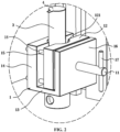
- the mount 1 includes a second driving member 11 and at least two clamping blocks, a clamping groove 121 is disposed on each of the at least two clamping blocks, all clamping grooves 121 enclose to form a clamping space configured to clamp the core 3, at least some clamping blocks are moving clamping blocks 12, the second driving member 11 is drivingly connected to the moving clamping block 12 to drive the moving clamping block 12 to move to clamp or release the core 3.
- a groove bottom of the clamping groove 121 is configured as an arc surface to improve a degree of fitness between the clamping block and the core 3.
- the second driving member 11 drives the moving clamping blocks 12 to clamp the core 3 so that the mount 1 can adapt to fixing cores 3 with different sizes, thereby implementing tensile tests for welding between cores 3 with different sizes and collection plates 4 with different sizes and improving the compatibility of the tensile test apparatus for welding of the collection plate of the cell.
- a clamping platform 1211 is disposed on a groove wall of the clamping groove 121 and protrudes towards a central axial direction of the clamping space, a portion of the core 3 is abutted against the clamping platform 1211, and an avoidance space for avoiding the central hole 31 is formed between two clamping platforms 1211 at intervals. It is to be noted that the clamping platform 1211 does not affect the exposure of the central hole 31 to avoid that the peel rod 21 cannot pass through the central hole 31.
- the clamping platform 1211 facilitates the placement of the core 3 when the mount 1 clamps the core 3, that is, a relative height of the core 3 in the clamping space can be positioned, thereby facilitating the fixation of the core 3.
- the mount 1 further includes a baseplate 13, some clamping blocks are fixed clamping blocks 14, the fixed clamping block 14 is fixed on the baseplate 13, a guide rod 15 is disposed on the moving clamping block 12, and a guide hole 18 is disposed in the fixed clamping block 14, where the guide rod 15 is slidably connected to the guide hole 18.
- two clamping blocks are disposed in total, that is, a fixed clamping block 14 and a moving clamping block 12 are disposed in a second direction at intervals (the second direction is a Y direction in FIG. 1 ).
- the matching between the guide rod 15 and the guide hole 18 can effectively improve a movement guide of the moving clamping block 12, prevent a position offset of the moving clamping block 12 and ensure a degree of fitness between the clamping block and the core 3.
- the guide rod 15 may also be disposed in the fixed clamping block 14, and the guide hole 18 may also be disposed in the moving clamping block 12.
- the mount 1 further includes a mounting plate 16, the mounting plate 16 is disposed on a side of the moving clamping block 12 facing away from the fixed clamping block 14 at intervals, the second driving member 11 is rotatably connected to the mounting plate 16, one end of the second driving member 11 is connected to the moving clamping block 12, and the other end of the second driving member 11 passes through the mounting plate 16 and extends beyond the mount 1.
- the second driving member 11 is a lead screw
- a lead screw nut is embedded in the mounting plate 16
- the lead screw is slidably connected to the lead screw nut
- the lead screw is rotatably connected to the moving clamping block 12
- a handle 17 is disposed on one end of the lead screw facing away from the moving clamping block 12.
- the handle 17 rotates the handle 17 so that the lead screw rotates relative to the mounting plate 16, thereby pushing the moving clamping block 12 to move.
- the manner of manual driving by using the handle 17 is conducive to controlling the movement accuracy of the moving clamping block 12.
- the lead screw may also be driven by using an electric motor to implement the automatic clamping of the core 3.
- the second driving member 11 may also be a screw, and a threaded hole is disposed in the mounting plate 16. The screw is matched with the threaded hole through a screw thread, and the screw is rotated to implement the push of the moving clamping block 12.
- the peel rod 21 is detachably connected to the tension meter 22.
- a through hole is disposed in the peel rod 21, and a threaded hole is disposed in the tension meter 22.
- a bolt is screwed to the threaded hole through the through hole so that the peel rod 21 is connected to the tension meter 22.
- connection body 2121 is movably connected to the support portion 2122 so that spacing between the support portion 2122 and the pushing portion 211 is adjustable.
- the spacing between the support portion 2122 and the pushing portion 211 is adjusted to adapt to cores 3 with different sizes. For example, when a core 3 with a relatively small diameter size is tested, the spacing between the support portion 2122 and the pushing portion 211 is shortened, and a distance of a force arm between the support portion 2122 and the pushing portion 211 is reduced so that a force felt by the support portion 2122 is closer to a force felt by the pushing portion 211, the test accuracy is higher and the peel rod 21 is not easy to bend.
- the spacing between the support portion 2122 and the pushing portion 211 may also be adjusted through the movable connection between the connection body 2121 and the pushing portion 211 in addition to the movable connection between the connection body 2121 and the support portion 2122.
- a manner of the movable connection may be that a waist hole is disposed in the connection body 2121, a threaded hole is disposed in the support portion 2122 or the pushing portion 211 and a bolt passes through the waist-shaped hole and is screwed to the threaded hole to implement the connection between the connection body 2121 and the support portion 2122 or the pushing portion 211, and a position of the bolt at the waist-shaped hole is adjusted to adjust the spacing between the support portion 2122 and the pushing portion 211.
- the tensile test apparatus for welding of a collection plate of a cell further includes a first mounting base 5 and a second mounting base 6 that are disposed at an included angle.
- the first mounting base 5 is disposed to be perpendicular to the second mounting base 6.
- the mount 1 is disposed on the first mounting base 5, and the first driving member 23 is disposed on the second mounting base 6 and is located above the mount 1.
- the first mounting base 5 and the second mounting base 6 facilitate determining the relative positions of the mount 1 and the first driving member 23 to improve the accuracy of driving the peel rod 21 by the first driving member 23 to peel off the core 3 in the mount 1.
- a working principle of the tensile test apparatus for a collection plate 4 of a cell is as follows: the central hole 31 of the core 3 is sleeved on the pushing portion 211 and is abutted against the clamping platform 1211 of the fixed clamping block 14, the second driving member 11 is started so that the moving clamping block 12 clamps the core 3, the first driving member 23 is started to pull the tension meter 22 to drive the peel rod 21 to move upward so that the pushing portion 211 abuts against the collection plate 4 until the collection plate 4 is separated from the core 3, and the data on the tension meter 22 is read.
- the tensile test apparatus for a collection plate 4 of a cell is simple in structure, convenient in operation and simple in measurement and has high test efficiency.
Landscapes
- Chemical & Material Sciences (AREA)
- Biochemistry (AREA)
- General Physics & Mathematics (AREA)
- Pathology (AREA)
- Physics & Mathematics (AREA)
- Health & Medical Sciences (AREA)
- Life Sciences & Earth Sciences (AREA)
- Immunology (AREA)
- Analytical Chemistry (AREA)
- General Health & Medical Sciences (AREA)
- Chemical Kinetics & Catalysis (AREA)
- Electrochemistry (AREA)
- General Chemical & Material Sciences (AREA)
- Engineering & Computer Science (AREA)
- Manufacturing & Machinery (AREA)
- Investigating Strength Of Materials By Application Of Mechanical Stress (AREA)
- Secondary Cells (AREA)
Applications Claiming Priority (2)
| Application Number | Priority Date | Filing Date | Title |
|---|---|---|---|
| CN202322172517.6U CN220709014U (zh) | 2023-08-11 | 2023-08-11 | 电芯汇流盘焊接拉力测试装置 |
| PCT/CN2024/109874 WO2024245470A1 (zh) | 2023-08-11 | 2024-08-05 | 电芯汇流盘焊接拉力测试装置 |
Publications (2)
| Publication Number | Publication Date |
|---|---|
| EP4530605A1 true EP4530605A1 (de) | 2025-04-02 |
| EP4530605A4 EP4530605A4 (de) | 2025-11-12 |
Family
ID=90452484
Family Applications (1)
| Application Number | Title | Priority Date | Filing Date |
|---|---|---|---|
| EP24814661.5A Pending EP4530605A4 (de) | 2023-08-11 | 2024-08-05 | Zugprüfvorrichtung zum schweissen einer zellenstromkollektorscheibe |
Country Status (3)
| Country | Link |
|---|---|
| EP (1) | EP4530605A4 (de) |
| CN (1) | CN220709014U (de) |
| WO (1) | WO2024245470A1 (de) |
Families Citing this family (1)
| Publication number | Priority date | Publication date | Assignee | Title |
|---|---|---|---|---|
| CN220709014U (zh) * | 2023-08-11 | 2024-04-02 | 惠州亿纬锂能股份有限公司 | 电芯汇流盘焊接拉力测试装置 |
Family Cites Families (11)
| Publication number | Priority date | Publication date | Assignee | Title |
|---|---|---|---|---|
| JP3361483B2 (ja) * | 1999-07-19 | 2003-01-07 | 基礎地盤コンサルタンツ株式会社 | 機能性保孔管式孔内載荷試験装置 |
| CN104390855B (zh) * | 2014-12-12 | 2017-07-11 | 河北银隆新能源有限公司 | 电池极板焊接性能测试夹具及测试方法 |
| CN108267368A (zh) * | 2018-03-15 | 2018-07-10 | 河北银隆新能源有限公司 | 拉力测试结构 |
| CN211401919U (zh) * | 2019-10-17 | 2020-09-01 | 深圳市博恩实业有限公司 | 一种具有挤压功能的电子剥离测试仪 |
| CN213456421U (zh) * | 2020-09-30 | 2021-06-15 | 武汉大雁软件有限公司 | 一种集流盘焊接拉力测试装置及电池生产线 |
| CN213544356U (zh) * | 2020-11-02 | 2021-06-25 | 青岛艾斯达特新材料科技有限公司 | 一种纳米涂层表面粘连度检测装置 |
| EP4306258B1 (de) * | 2021-03-08 | 2025-11-12 | LG Energy Solution, Ltd. | Vorrichtung zur schweissqualitätsinspektion und verfahren zur schweissqualitätsinspektion |
| CN218330985U (zh) * | 2022-05-27 | 2023-01-17 | 无锡先导智能装备股份有限公司 | 持紧针及圆柱电池焊接检测装置 |
| CN219284859U (zh) * | 2022-12-05 | 2023-06-30 | 惠州金源精密自动化设备有限公司 | 电芯与汇流盘焊接强度测试装置 |
| CN115815769A (zh) * | 2022-12-13 | 2023-03-21 | 创科无线普通合伙 | 用于电池的点底焊接的系统和监控方法 |
| CN220709014U (zh) * | 2023-08-11 | 2024-04-02 | 惠州亿纬锂能股份有限公司 | 电芯汇流盘焊接拉力测试装置 |
-
2023
- 2023-08-11 CN CN202322172517.6U patent/CN220709014U/zh active Active
-
2024
- 2024-08-05 EP EP24814661.5A patent/EP4530605A4/de active Pending
- 2024-08-05 WO PCT/CN2024/109874 patent/WO2024245470A1/zh active Pending
Also Published As
| Publication number | Publication date |
|---|---|
| EP4530605A4 (de) | 2025-11-12 |
| CN220709014U (zh) | 2024-04-02 |
| WO2024245470A1 (zh) | 2024-12-05 |
Similar Documents
| Publication | Publication Date | Title |
|---|---|---|
| EP4530605A1 (de) | Zugprüfvorrichtung zum schweissen einer zellenstromkollektorscheibe | |
| CN209979699U (zh) | 一种电芯夹具及电芯检测装置 | |
| CN116539357B (zh) | 一种全自动钻芯和直拔一体机及其检测方法 | |
| CN219996702U (zh) | 一种拉伸试验装置 | |
| CN110253338A (zh) | 刀具检测设备 | |
| CN212109802U (zh) | 一种测量分条钢带毛刺设备的传动机构 | |
| CN210400311U (zh) | 水泵法兰和叶轮检测设备 | |
| CN118730712A (zh) | 一种柔性太阳能电池力学性能测试装置及测试方法 | |
| CN219475171U (zh) | 一种电脑式剥离力试验机 | |
| CN212989039U (zh) | 保护膜拉力测试机 | |
| CN219015876U (zh) | 一种电池拉力测试夹具及拉力测试装置 | |
| CN115318153A (zh) | 一种检验科用试管混匀装置 | |
| CN219434740U (zh) | 一种超声波探头固定装置 | |
| CN209542410U (zh) | 一种电池片背电场附着力测试装置 | |
| CN222887698U (zh) | 一种互感器检测夹具 | |
| CN222938885U (zh) | 试样拉伸装置 | |
| CN221650484U (zh) | 一种带电检测操作手臂装置 | |
| CN223346704U (zh) | 一种透明胶带剥离拉力测试机 | |
| CN215598689U (zh) | 一种消防工具手柄抗拉性能测试装置 | |
| CN223955283U (zh) | 一种水利工程建筑用防水材料强度检测装置 | |
| CN216925408U (zh) | 一种丝杆间隙消除工装 | |
| CN219927995U (zh) | 无人机吊装式声学成像定位仪 | |
| CN212145151U (zh) | 一种适用于多规格圆管的抓取工具 | |
| CN221405973U (zh) | 齿槽转矩测试电机对托装置 | |
| CN220113155U (zh) | 一种可调节的摇摆机结构 |
Legal Events
| Date | Code | Title | Description |
|---|---|---|---|
| STAA | Information on the status of an ep patent application or granted ep patent |
Free format text: STATUS: THE INTERNATIONAL PUBLICATION HAS BEEN MADE |
|
| PUAI | Public reference made under article 153(3) epc to a published international application that has entered the european phase |
Free format text: ORIGINAL CODE: 0009012 |
|
| STAA | Information on the status of an ep patent application or granted ep patent |
Free format text: STATUS: REQUEST FOR EXAMINATION WAS MADE |
|
| 17P | Request for examination filed |
Effective date: 20241224 |
|
| AK | Designated contracting states |
Kind code of ref document: A1 Designated state(s): AL AT BE BG CH CY CZ DE DK EE ES FI FR GB GR HR HU IE IS IT LI LT LU LV MC ME MK MT NL NO PL PT RO RS SE SI SK SM TR |
|
| REG | Reference to a national code |
Ref country code: DE Ref legal event code: R079 Free format text: PREVIOUS MAIN CLASS: G01N0019040000 Ipc: G01N0003080000 |
|
| A4 | Supplementary search report drawn up and despatched |
Effective date: 20251010 |
|
| RIC1 | Information provided on ipc code assigned before grant |
Ipc: G01N 3/08 20060101AFI20251006BHEP Ipc: G01N 3/04 20060101ALI20251006BHEP Ipc: H01M 10/42 20060101ALI20251006BHEP Ipc: H01M 50/536 20210101ALI20251006BHEP |