EP4530239A1 - Garnbox, garnabstreifverfahren, garnabstreifvorrichtung und speichermedien - Google Patents
Garnbox, garnabstreifverfahren, garnabstreifvorrichtung und speichermedien Download PDFInfo
- Publication number
- EP4530239A1 EP4530239A1 EP24180030.9A EP24180030A EP4530239A1 EP 4530239 A1 EP4530239 A1 EP 4530239A1 EP 24180030 A EP24180030 A EP 24180030A EP 4530239 A1 EP4530239 A1 EP 4530239A1
- Authority
- EP
- European Patent Office
- Prior art keywords
- yarn
- spindle
- rod
- target
- spindles
- Prior art date
- Legal status (The legal status is an assumption and is not a legal conclusion. Google has not performed a legal analysis and makes no representation as to the accuracy of the status listed.)
- Pending
Links
Images


Classifications
-
- B—PERFORMING OPERATIONS; TRANSPORTING
- B65—CONVEYING; PACKING; STORING; HANDLING THIN OR FILAMENTARY MATERIAL
- B65H—HANDLING THIN OR FILAMENTARY MATERIAL, e.g. SHEETS, WEBS, CABLES
- B65H54/00—Winding, coiling, or depositing filamentary material
- B65H54/70—Other constructional features of yarn-winding machines
- B65H54/705—Arrangements for reducing hairyness of the filamentary material
-
- B—PERFORMING OPERATIONS; TRANSPORTING
- B65—CONVEYING; PACKING; STORING; HANDLING THIN OR FILAMENTARY MATERIAL
- B65H—HANDLING THIN OR FILAMENTARY MATERIAL, e.g. SHEETS, WEBS, CABLES
- B65H54/00—Winding, coiling, or depositing filamentary material
- B65H54/02—Winding and traversing material on to reels, bobbins, tubes, or like package cores or formers
- B65H54/40—Arrangements for rotating packages
- B65H54/54—Arrangements for supporting cores or formers at winding stations; Securing cores or formers to driving members
- B65H54/547—Cantilever supporting arrangements
-
- B—PERFORMING OPERATIONS; TRANSPORTING
- B65—CONVEYING; PACKING; STORING; HANDLING THIN OR FILAMENTARY MATERIAL
- B65H—HANDLING THIN OR FILAMENTARY MATERIAL, e.g. SHEETS, WEBS, CABLES
- B65H54/00—Winding, coiling, or depositing filamentary material
- B65H54/70—Other constructional features of yarn-winding machines
- B65H54/707—Suction generating system
-
- B—PERFORMING OPERATIONS; TRANSPORTING
- B65—CONVEYING; PACKING; STORING; HANDLING THIN OR FILAMENTARY MATERIAL
- B65H—HANDLING THIN OR FILAMENTARY MATERIAL, e.g. SHEETS, WEBS, CABLES
- B65H54/00—Winding, coiling, or depositing filamentary material
- B65H54/70—Other constructional features of yarn-winding machines
- B65H54/71—Arrangements for severing filamentary materials
-
- B—PERFORMING OPERATIONS; TRANSPORTING
- B65—CONVEYING; PACKING; STORING; HANDLING THIN OR FILAMENTARY MATERIAL
- B65H—HANDLING THIN OR FILAMENTARY MATERIAL, e.g. SHEETS, WEBS, CABLES
- B65H54/00—Winding, coiling, or depositing filamentary material
- B65H54/86—Arrangements for taking-up waste material before or after winding or depositing
- B65H54/88—Arrangements for taking-up waste material before or after winding or depositing by means of pneumatic arrangements, e.g. suction guns
-
- B—PERFORMING OPERATIONS; TRANSPORTING
- B65—CONVEYING; PACKING; STORING; HANDLING THIN OR FILAMENTARY MATERIAL
- B65H—HANDLING THIN OR FILAMENTARY MATERIAL, e.g. SHEETS, WEBS, CABLES
- B65H63/00—Warning or safety devices, e.g. automatic fault detectors, stop-motions ; Quality control of the package
- B65H63/02—Warning or safety devices, e.g. automatic fault detectors, stop-motions ; Quality control of the package responsive to reduction in material tension, failure of supply, or breakage, of material
-
- B—PERFORMING OPERATIONS; TRANSPORTING
- B65—CONVEYING; PACKING; STORING; HANDLING THIN OR FILAMENTARY MATERIAL
- B65H—HANDLING THIN OR FILAMENTARY MATERIAL, e.g. SHEETS, WEBS, CABLES
- B65H63/00—Warning or safety devices, e.g. automatic fault detectors, stop-motions ; Quality control of the package
- B65H63/04—Warning or safety devices, e.g. automatic fault detectors, stop-motions ; Quality control of the package responsive to excessive tension or irregular operation of apparatus
-
- B—PERFORMING OPERATIONS; TRANSPORTING
- B65—CONVEYING; PACKING; STORING; HANDLING THIN OR FILAMENTARY MATERIAL
- B65H—HANDLING THIN OR FILAMENTARY MATERIAL, e.g. SHEETS, WEBS, CABLES
- B65H63/00—Warning or safety devices, e.g. automatic fault detectors, stop-motions ; Quality control of the package
- B65H63/06—Warning or safety devices, e.g. automatic fault detectors, stop-motions ; Quality control of the package responsive to presence of irregularities in running material, e.g. for severing the material at irregularities ; Control of the correct working of the yarn cleaner
- B65H63/062—Electronic slub detector
-
- B—PERFORMING OPERATIONS; TRANSPORTING
- B65—CONVEYING; PACKING; STORING; HANDLING THIN OR FILAMENTARY MATERIAL
- B65H—HANDLING THIN OR FILAMENTARY MATERIAL, e.g. SHEETS, WEBS, CABLES
- B65H67/00—Replacing or removing cores, receptacles, or completed packages at paying-out, winding, or depositing stations
- B65H67/04—Arrangements for removing completed take-up packages and or replacing by cores, formers, or empty receptacles at winding or depositing stations; Transferring material between adjacent full and empty take-up elements
- B65H67/0405—Arrangements for removing completed take-up packages or for loading an empty core
- B65H67/0411—Arrangements for removing completed take-up packages or for loading an empty core for removing completed take-up packages
-
- B—PERFORMING OPERATIONS; TRANSPORTING
- B65—CONVEYING; PACKING; STORING; HANDLING THIN OR FILAMENTARY MATERIAL
- B65H—HANDLING THIN OR FILAMENTARY MATERIAL, e.g. SHEETS, WEBS, CABLES
- B65H67/00—Replacing or removing cores, receptacles, or completed packages at paying-out, winding, or depositing stations
- B65H67/08—Automatic end-finding and material-interconnecting arrangements
- B65H67/081—Automatic end-finding and material-interconnecting arrangements acting after interruption of the winding process, e.g. yarn breakage, yarn cut or package replacement
- B65H67/085—Automatic end-finding and material-interconnecting arrangements acting after interruption of the winding process, e.g. yarn breakage, yarn cut or package replacement end-finding at the take-up package, e.g. by suction and reverse package rotation
-
- B—PERFORMING OPERATIONS; TRANSPORTING
- B65—CONVEYING; PACKING; STORING; HANDLING THIN OR FILAMENTARY MATERIAL
- B65H—HANDLING THIN OR FILAMENTARY MATERIAL, e.g. SHEETS, WEBS, CABLES
- B65H2553/00—Sensing or detecting means
- B65H2553/40—Sensing or detecting means using optical, e.g. photographic, elements
- B65H2553/42—Cameras
-
- B—PERFORMING OPERATIONS; TRANSPORTING
- B65—CONVEYING; PACKING; STORING; HANDLING THIN OR FILAMENTARY MATERIAL
- B65H—HANDLING THIN OR FILAMENTARY MATERIAL, e.g. SHEETS, WEBS, CABLES
- B65H2557/00—Means for control not provided for in groups B65H2551/00 - B65H2555/00
- B65H2557/60—Details of processes or procedures
- B65H2557/61—Details of processes or procedures for calibrating
-
- B—PERFORMING OPERATIONS; TRANSPORTING
- B65—CONVEYING; PACKING; STORING; HANDLING THIN OR FILAMENTARY MATERIAL
- B65H—HANDLING THIN OR FILAMENTARY MATERIAL, e.g. SHEETS, WEBS, CABLES
- B65H2557/00—Means for control not provided for in groups B65H2551/00 - B65H2555/00
- B65H2557/60—Details of processes or procedures
- B65H2557/64—Details of processes or procedures for detecting type or properties of handled material
-
- B—PERFORMING OPERATIONS; TRANSPORTING
- B65—CONVEYING; PACKING; STORING; HANDLING THIN OR FILAMENTARY MATERIAL
- B65H—HANDLING THIN OR FILAMENTARY MATERIAL, e.g. SHEETS, WEBS, CABLES
- B65H2701/00—Handled material; Storage means
- B65H2701/10—Handled articles or webs
- B65H2701/17—Nature of material
- B65H2701/174—Textile; fibres
-
- B—PERFORMING OPERATIONS; TRANSPORTING
- B65—CONVEYING; PACKING; STORING; HANDLING THIN OR FILAMENTARY MATERIAL
- B65H—HANDLING THIN OR FILAMENTARY MATERIAL, e.g. SHEETS, WEBS, CABLES
- B65H2701/00—Handled material; Storage means
- B65H2701/30—Handled filamentary material
- B65H2701/31—Textiles threads or artificial strands of filaments
Definitions
- the present disclosure relates to the field of mechanical and computer technologies.
- the present disclosure specifically relates to a yarn box, a yarn stripping method, a yarn stripping apparatus, an electronic device and a storage media.
- a winding machine In the production process of chemical fiber products, a winding machine is used to wind the fiber yarn to obtain a plurality of yarn spindles. These yarn spindles are moved from the winding machine to a yarn box through a doffer for temporary storage, to perform subsequent operations corresponding to the process flow.
- the fiber yarn on these yarn spindles may have a length of yarn hanging down, the drooping fiber yarn of adjacent yarn spindles may become knotted or entangled in other machines or components during the movement.
- the quality of this layer of fiber yarn on the outer surface of the yarn spindle is poor due to the deceleration of the winding machine.
- the yarn stripping operation needs to be performed on the yarn spindle after the winding of the yarn spindle is completed.
- the present disclosure provides a yarn box, a yarn stripping method, a yarn stripping apparatus, an electronic device and a storage media.
- a yarn box including:
- a yarn stripping method including:
- a yarn stripping apparatus including:
- an electronic device including:
- a non-transitory computer-readable storage medium storing a computer instruction thereon, and the computer instruction is used to cause a computer to execute the yarn stripping method according to any one of the embodiments of the present disclosure.
- a computer program product including a computer program, and the computer program implements any point cloud model pre-training method, any point cloud model training method, any point cloud detection method or any point cloud segmentation method according to the embodiments of the present disclosure, when executed by a processor.
- one or more yarn receiving rods are provided in the yarn box, one end of the yarn receiving rod is connected to the support in the yarn box, and the other end is configured to correspond to the discharge port of the doffer to enable a plurality of yarn spindles unloaded from the discharge port to be sleeved in the yarn receiving rod.
- the yarn box can store a plurality of yarn spindles.
- the yarn stripping rod with one end slidably connected to the support is provided in the yarn box, and the yarn stripping rod can slide to the yarn stripping position corresponding to the first yarn receiving rod among the one or more yarn receiving rods when the plurality of yarn spindles are sleeved in the first yarn receiving rod and the number of yarn spindles on the first yarn receiving rod reaches the set condition, so that the yarn strippers on the yarn stripping rod can strip the fiber yarn on the outer surfaces of respective corresponding yarn spindles.
- the arrangement of the yarn stripping rod in the yarn box can be convenient to strip the fiber yarn hanging down from the yarn spindles in advance before the yarn spindles are stored or transferred, and can avoid the fiber yarn on the yarn spindles from enwinding other devices during subsequent storage or transfer.
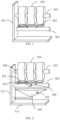
- FIG 1 is a structural diagram of a yarn box according to an embodiment of the present disclosure.
- the yarn box includes a support 101, a yarn stripping rod 102 and at least one yarn receiving rod 103.
- a first end of the yarn receiving rod 103 is connected to the support 101, and a second end of the yarn receiving rod 103 is configured to correspond to a discharge port of a doffer to enable a plurality of yarn spindles 104 unloaded from the discharge port to be sleeved outside the yarn receiving rod 103.
- a first end of the yarn stripping rod 102 is slidably connected to the support 101, the yarn stripping rod 102 is configured to slide to a yarn stripping position corresponding to a first yarn receiving rod 103 among the at least one yarn receiving rod 103 when the plurality of yarn spindles 104 are sleeved outside the first yarn receiving rod 103 and the number of yarn spindles 104 of the first yarn receiving rod 103 reaches a set condition, the yarn stripping rod 102 is provided with a plurality of yarn strippers 105 corresponding to the plurality of yarn spindles 104 one by one, and the yarn strippers 105 are configured to strip the fiber yarn on outer surfaces of the corresponding yarn spindles 104.
- the doffer can move between the winding machine and the yarn box, the feed port of the doffer corresponds to the discharge port of the winding machine, and the doffer is configured to extract a plurality of yarn spindles 104 from the winding machine and move the plurality of yarn spindles 104 to the yarn box for storage.
- the yarn spindle 104 is a roll of yarn formed by winding the fiber yarn on a hollow cylinder.
- the fiber yarn on the outer surface of the yarn spindle 104 refer to a layer of fiber yarn on the outer surface of the yarn spindle, that is, the outermost layer of fiber yarn.
- one or more yarn receiving rods 103 can be provided in the yarn box.
- a plurality of yarn receiving rods 103 are arranged in multiple rows and columns parallel to each other.
- the support 101 stands on the ground, and the yarn receiving rod 103 is parallel to the ground, so that the second end of the yarn receiving rod 103 corresponds to the discharge port of the doffer.
- the first yarn receiving rod 103 is the yarn receiving rod 103 that is feeding.
- the yarn spindles 104 fed to the first yarn receiving rod 103 meet the set condition, the yarn spindles 104 on the first yarn receiving rod 103 start to be stripped.
- the above set condition may be that the number of yarn spindles 104 reaches a set number threshold. For example, when the number of yarn spindles 104 is greater than 8, it is determined that the number of yarn spindles 104 reaches the set condition.
- one or more yam stripping rods 102 may be provided in the yarn box.
- Each yarn stripping rod 102 corresponds to one or more yarn receiving rods 103, to strip the fiber yarn on the outer surface (that is, the outermost layer of fiber yarn) of the yarn spindle 104 on the one or more yarn receiving rods 103. If one yarn stripping rod 102 corresponds to a plurality of yarn receiving rods 103, then: when a certain yarn receiving rod 103 has just finished feeding, the yarn stripping rod 102 can be slid to a position close to this yarn receiving rod 103, so that the yarn stripping rod 102 strips the fiber yarn on the outer surface of the yarn spindle 104 on the yarn receiving rod 103.
- the support 101 is provided with a slide rail
- the first end of the yarn stripping rod 102 is provided with a pulley
- the pulley is embedded in the slide rail and slides close to the first yarn receiving rod 103.
- the slide rail can also be provided with clamping blocks corresponding to the yarn receiving rod 103 respectively.
- the clamping block corresponding to the yarn stripping position can extend into the slide rail to clamp the yarn stripping rod 102, so as to fix the yarn stripping rod 102.
- one or more yarn receiving rods 103 are provided in the yarn box, one end of the yarn receiving rod 103 is connected to the support 101 in the yarn box, and the other end is configured to correspond to the discharge port of the doffer to enable a plurality of yarn spindles 104 unloaded from the discharge port to be sleeved in the yarn receiving rod 103.
- the yarn box can store a plurality of yarn spindles 104.
- the yarn stripping rod 102 with one end slidably connected to the support 101 is provided in the yarn box, and the yarn stripping rod 102 can slide to the yarn stripping position corresponding to the first yarn receiving rod 103 among the one or more yarn receiving rods 103 when the plurality of yarn spindles 104 are sleeved in the first yarn receiving rod 103 and the number of yarn spindles 104 on the first yarn receiving rod 103 reaches the set condition, so that the yarn strippers 105 on the yarn stripping rod 102 can strip the fiber yarn on the outer surfaces of respective corresponding yarn spindles 104.
- the arrangement of the yarn stripping rod 102 in the yarn box can be convenient to strip the outermost layer of fiber yarn on the yarn spindle 104 in advance before the yarn spindle 104 is stored or transferred, and can not only avoid the fiber yarn from enwinding other devices due to the outermost layer of loose fiber yarn or the drooping yarn head on the yarn spindle 104 during subsequent storage or transfer, but also complete the yarn stripping process efficiently under better working conditions, improving the production efficiency.
- FIG 2 is a structural diagram of a yarn box according to another embodiment of the present disclosure.
- the yarn stripping rod 102 is further provided with a camera 106.
- the camera 106 is configured to photograph the plurality of yarn spindles 104 sleeved outside the first yarn receiving rod 103, to obtain a yarn spindle image for determining a target yarn spindle 104 with drooping fiber yarn among the plurality of yarn spindles 104.
- the yarn stripper 105 is telescopically connected to the yarn stripping rod 102, and configured to extend from the yarn stripping rod 102 towards the target yarn spindle 104 when a corresponding yarn spindle 104 is the target yarn spindle 104, to strip the fiber yarn on an outer surface of the target yarn spindle 104.
- the yarn stripping rod 102 may be provided with one or more cameras 106 to photograph all the yarn spindles 104 on the yarn receiving rod 103 from various angles.
- the camera 106 provides the image of the yarn spindle 104 to the background service, and the background service determines the target yarn spindle 104 with drooping fiber yarn based on the image of the yarn spindle 104.
- the background service can use an image recognition model to recognize the image, to determine the target yarn spindle.
- the drooping fiber yarn refers to the fiber yarn which hangs down from the side of the yarn spindle 104 and of which the end is suspended in the air and does not contact the side of the yarn spindle 104.
- the yarn strippers 105 corresponding to the target yarn spindles 104 respectively extend from the yarn stripping rod 102 towards the target yarn spindles 104.
- the yarn stripper 105 is vertically connected to the yarn stripping rod 102 through a telescopic rod 107.
- the telescopic rod 107 is extended to move the yarn stripper 105 close to the target yarn spindle 104. After the yarn stripper 105 strips the fiber yarn on the outer surface, the telescopic rod 107 retracts to move the yarn stripper 105 away from the target yarn spindle 104.
- the camera 106 is used to photograph the plurality of yarn spindles 104 on the first yarn receiving rod 103, and the target yarn spindle 104 with drooping fiber yarn can be accurately recognized through visual recognition.
- the retractable yarn stripper 105 is provided in the yarn stripping rod 102, to facilitate stripping the fiber yarn on the outer surface of the target yarn spindle 104 and improve the stripping efficiency of the fiber yarn.
- the quality of this layer of fiber yarn on the outer surface is also poor.
- stripping the fiber yarn on the outer surface of the target yarn spindle can not only strip the drooping fiber yarn of the yarn spindle to avoid the fiber yarn from enwinding other devices, but also improve the quality of the fiber yarn of the yarn spindle.
- the fiber yarn on the outer surfaces may not be stripped to improve the stripping efficiency for the yarn spindles in the yarn box.
- each yarn receiving rod 103 is rotatably connected to the support 101, and the yarn spindle image captured by the camera 106 is also used to identify the direction in which the fiber yarn of the plurality of yarn spindles sleeved on the first yarn receiving rod 103 is wound into spindles, that is, the first direction.
- the first yarn receiving rod 103 is configured to rotate in an opposite direction of the first direction to rotate a yarn spindle 104 sleeved outside the first yarn receiving rod 103 and make the fiber yarn wound on the yarn spindle 104 hang down before determining the target yarn spindle with drooping fiber yarn among the plurality of yarn spindles.
- the yarn receiving rod 103 can be connected to the support 101 through a rotating shaft 108, and can rotate clockwise or counterclockwise.
- the first yarn receiving rod 103 is firstly rotated before determining which yarn spindles on the first yarn receiving rod are the target yarn spindles 104.
- the direction of rotation is opposite to the direction in which the fiber yarn of the yarn spindles 104 is wound into spindles, so that the fiber yarn wound on the yarn spindles 104 can hang down, that is, the end of the fiber yarn is suspended.
- the first yarn receiving rod 103 is rotated in advance to rotate the yarn spindle 104 and make the fiber yarn wound on the yarn spindle 104 hang down,
- the end of the fiber yarn is drooped as much as possible, and this yarn spindle is determined as the target yarn spindle, so that the quality of the fiber yarn of the yarn spindle can be improved subsequently by stripping the fiber yarn on the outer surface.
- the possibility of the yarn spindle 104 in the yarn box being hooked or entangled with other components during the subsequent transfer process can be further reduced.
- the yarn stripper 105 may include a yarn adsorption device and a yarn cutting knife.
- the yarn adsorption device is configured to adsorb an end of the drooping fiber yarn of the target yarn spindle when the yarn stripper 105 extends from the yarn stripping rod 102 towards the target yarn spindle so that the end is fixed on the yarn adsorption device, and drive the target yarn spindle to rotate in the opposite direction to the first direction so that the fiber yarn on the outer surface of the target yarn spindle is rolled out.
- the yarn cutting knife is configured to cut the fiber yarn connected between the yarn adsorption device and the target yarn spindle when the adsorption time of the yarn adsorption device reaches a set threshold.
- the yarn adsorption device is rotatably connected to the yarn stripper 105.
- the yarn adsorption device rotates in the opposite direction of the first direction while adsorbing the end of the drooping fiber yarn of the target yarn spindle, so that the fiber yarn on the target yarn spindle is rolled out and rolled into the yarn adsorption device.
- the yarn cutting knife is retractably and slidably connected to the yarn stripper.
- the yarn cutting knife moves and approaches the fiber yarn that is connected to the yarn adsorption device and the target yarn spindle to cut the fiber yarn.
- the end of the drooping fiber yarn of the target yarn spindle is fixed on the yarn adsorption device through the yarn adsorption device, and then the yarn adsorption device drives the target yarn spindle to rotate in the opposite direction of the first direction, so that the fiber yarn on the outer surface of the target yarn spindle can be rolled out.
- the yarn cutting knife moves and approaches the fiber yarn that is connected to the yarn adsorption device and the target yarn spindle to cut the fiber yarn, thereby achieving the effect of stripping the fiber yarn on the outer surface of the yarn spindle by the yarn stripper.
- the first yarn receiving rod 103 is further configured to, when the yarn adsorption device adsorbs the fiber yarn on the outer surface of the target yarn spindle, rotate in the opposite direction to the first direction to rotate the target yarn spindle so that the fiber yarn on the outer surface of the target yarn spindle is rolled out.
- the first yarn receiving rod is controlled to rotate in the direction opposite to the direction in which the fiber yarn of the target yarn spindle is wound into spindle while the yarn stripper performs yarn stripping on the target yarn spindle, which can speed up the rotation of the target yarn spindle in the opposite direction, and thus accelerate the speed at which the fiber yarn on the outer surface of the target yarn spindle is rolled out, thereby improving the stripping efficiency of the yarn stripper.
- the yarn stripper 105 is slidably connected to the yarn stripping rod 102, and the yarn stripper 105 is configured to, when the corresponding yarn spindle 104 is the target yarn spindle 104, slide on the yarn stripping rod 102 to calibrate corresponding positions of the yarn stripper 105 and the target yarn spindle 104.
- the yarn stripping rod 102 may be cylindrical.
- the yarn stripper 105 is connected to the yarn stripping rod 102 through a telescopic rod.
- the first end of the telescopic rod is an elastic clamping groove, which clamps the yarn stripping rod 102.
- the second end of the telescopic rod is connected to the yarn stripper 105.
- the clamping groove can be tightened to fix the position of the yarn stripper 105 on the yarn stripping rod 102, to facilitate the yarn stripper 105 to strip the fiber yarn on the outer surface of the target yarn spindle 104.
- the yarn stripper 105 by arranging the yarn stripper 105 to be slidably connected to the yarn stripping rod 102, the yarn stripper 105 can slide on the yarn stripping rod 102 before the yarn stripper 105 is used to perform yarn stripping on the target yarn spindle 104, thereby calibrating the yarn stripping positions of the yarn stripper 105 and the target yarn spindle 104, and improving the yarn stripping efficiency.
- the yarn box may further include a waste yarn container 109 located below the yarn stripping rod 102, having a container opening facing the yarn stripping rod 102, and configured to collect the fiber yarn stripped by the yarn stripper 105.
- the container opening is close to the yarn spindle 104 on the first yarn receiving rod 103.
- the orthographic projection of the container opening on the ground covers the orthographic projection of the yarn spindle 104 of the first yarn receiving rod 103 on the ground.
- the container opening may be in the shape of a funnel opening or a bag opening, etc.
- using the waste yarn container to collect the stripped fiber yarn can ensure that the yarn box is clean, and avoid the fiber yarn from falling everywhere.
- the yarn box further includes a vacuum adsorber (not shown in the figure) with a suction nozzle 110 disposed on an inner side of the waste yarn container and close to the container opening, where the vacuum adsorber is configured to adsorb the fiber yarn stripped by the yarn stripper 105, to collect the stripped fiber yarn in the waste yarn container.
- a vacuum adsorber (not shown in the figure) with a suction nozzle 110 disposed on an inner side of the waste yarn container and close to the container opening, where the vacuum adsorber is configured to adsorb the fiber yarn stripped by the yarn stripper 105, to collect the stripped fiber yarn in the waste yarn container.
- vacuum absorber and the waste yarn container can be integrated.
- using the vacuum absorber to absorb the fiber yarn stripped by the yarn stripper 105 can control the stripped fiber yarn to be accurately collected in the waste yarn container, and avoid the stripped fiber yarn from falling outside the waste yarn container.
- the support 101 in the yarn box may include a bottom plate 111 and a support plate 112 perpendicular to the bottom plate 111, the first end of the yarn receiving rod 103 is connected to the support plate 112 and parallel to the bottom plate 111, and the first end of the yarn stripping rod 102 is slidably connected to the support plate 112 and parallel to the bottom plate 111.
- the support 101 includes the bottom plate 111 and the support plate 112 perpendicular to the bottom plate 111, the yarn receiving rod 103 is connected to the support plate 112 and parallel to the bottom plate 111, and the yarn stripping rod 102 is connected to the support plate 112 and parallel to the bottom plate 111.
- the yarn receiving rod 103 is parallel to the bottom plate 111, thus facilitating the connection between the yarn receiving rod 103 and the doffer, so as to unload the yarn spindles 104.
- FIG 3 is a structural diagram of a yarn box according to another embodiment of the present disclosure.
- a plurality of pulleys are provided on a bottom plane of the bottom plate away from the support plate.
- a plurality of pulleys 113 are provided on the bottom plane of the bottom plate 111 of the yarn box, facilitating the movement of the yarn box to transfer the yarn spindles 104.
- FIG 4 is a flow chart of a yarn stripping method according to an embodiment of the present disclosure.
- the yarn stripping method may include:
- the structure and function of the yarn box can refer to any one of the foregoing embodiments and will not be described in detail here.
- discharge port of the doffer corresponds to the second end of the first yarn receiving rod in the yarn box, meaning that the discharge port is aligned with the second end.
- the above set condition may be that the number of yarn spindles reaches a set number threshold. For example, when the number of yarn spindles is greater than 8, it is determined that the number of yarn spindles reaches the set condition.
- one or more yarn strippers on the yarn stripping rod are controlled to strip the fiber yarn on the outer surfaces of the respective corresponding yarn spindles on the first yarn receiving rod.
- the yarn stripping rod in the yarn box slides to the yarn stripping position corresponding to the first yarn receiving rod, meaning that the yarn stripping rod slides to a position parallel and close to the first yarn receiving rod, so that the yarn strippers on the yarn stripping rod strip the fiber yarn on the outer surfaces of the yarn spindles on the first yarn receiving rod.
- the discharge port of the doffer is controlled to correspond to the first yarn receiving rod in the yarn box, and then the doffer is controlled to unload a plurality of yarn spindles from the discharge port, so that the plurality of yarn spindles can be sleeved outside the first yarn receiving rod.
- a plurality of yarn spindles can be stored in the yarn box.
- a camera is further provided on the yarn stripping rod, and the yarn strippers are telescopically connected to the yarn stripping rod.
- the above-mentioned step of controlling yarn strippers on the yarn stripping rod to strip the fiber yarn on outer surfaces of respective corresponding yarn spindles on the first yarn receiving rod may include: photographing the plurality of yarn spindles sleeved outside the first yarn receiving rod to obtain a first yarn spindle image; determining a target yarn spindle with drooping fiber yarn among the plurality of yarn spindles according to the first yarn spindle image; controlling a yarn stripper corresponding to the target yarn spindle to extend from the yarn stripping rod towards the target yarn spindle; and controlling the yarn stripper corresponding to the target yarn spindle to strip the fiber yarn on an outer surface of the target yarn spindle.
- the yarn stripping rod may be provided with one or more cameras to photograph all the yarn spindles on the yarn receiving rod from various angles.
- the yarn strippers corresponding to the target yarn spindles respectively extend from the yarn stripping rod towards the target yarn spindles.
- the yarn stripper is vertically connected to the yarn stripping rod through a telescopic rod.
- the telescopic rod is extended to move the yarn stripper close to the target yarn spindle.
- the telescopic rod retracts to move the yarn stripper away from the target yarn spindle.
- the camera is used to photograph the plurality of yarn spindles on the first yarn receiving rod, and the target yarn spindle with drooping fiber yarn can be accurately recognized through visual recognition.
- the retractable yarn stripper is provided in the yarn stripping rod, to facilitate stripping the fiber yarn on the outer surface of the target yarn spindle and improve the stripping efficiency of the fiber yarn.
- the quality of this layer of fiber yarn on the outer surface is also poor. Therefore, stripping the fiber yarn on the outer surface of the target yarn spindle can not only strip the drooping fiber yarn of the yarn spindle to avoid the fiber yarn from enwinding other devices, but also improve the quality of the fiber yarn of the yarn spindle.
- the fiber yarn on the outer surfaces may not be stripped to improve the stripping efficiency for the yarn spindles in the yarn box.
- the yarn strippers are slidably connected to the yarn stripping rod, and the above method may further include: before controlling the yarn stripper corresponding to the target yarn spindle to extend from the yarn stripping rod, controlling the yarn stripper corresponding to the target yarn spindle to slide on the yarn stripping rod to calibrate corresponding positions of the yarn stripper and the target yarn spindle.
- the yarn receiving rod can be connected to the support through a rotating shaft, and can rotate clockwise or counterclockwise.
- the first yarn receiving rod is firstly rotated when the number of yarn spindles of the first yarn receiving rod reaches the set condition, that is, before starting to prepare to perform yarn stripping on the yarn spindles of the first yarn receiving rod.
- the direction of rotation is opposite to the direction in which the fiber yarn of the yarn spindles is wound, so that the fiber yarn wound on the yarn spindles can hang down, that is, the end of the fiber yarn is suspended.
- the first yarn receiving rod before stripping the fiber yarn on the outer surface of the yarn spindle on the first yarn receiving rod, the first yarn receiving rod is rotated in advance to rotate the yarn spindle and make the fiber yarn wound on the yarn spindle hang down, In this way, for a yarn spindle that currently has no drooping fiber yarn but may have drooping fiber yarn in the future, the end of the fiber yarn is drooped as much as possible, so that the drooping fiber yarn can be stripped subsequently by stripping the fiber yarn on the outer surface, thereby further reducing the possibility of the yarn spindle being hooked or entangled with other components during the subsequent transfer process.
- the above step of determining a target yarn spindle with drooping fiber yarn among the plurality of yarn spindles according to the first yarn spindle image includes: inputting the first yarn spindle image into an image recognition model to obtain a first detection frame image output by the image recognition model, where the first detection frame image includes the first yarn spindle image and at least one detection frame including any drooping fiber yarn in the first yarn spindle image; and determining the target yarn spindle among the plurality of yarn spindles based on the position information of each detection frame in the first detection frame image.
- the above image recognition model may be a pre-trained model.
- the first detection frame image may include one or more detection frames, and each detection frame may include an end of one drooping fiber yarn.
- the detection frames include different drooping fiber yarn.
- each detection frame can be used to determine the yarn spindle corresponding to each detection frame, so as to determine the target yarn spindle.
- using the image recognition model to recognize the drooping fiber yarn in the yarn spindle image can improve the accuracy in recognizing the drooping fiber yarn.
- the above method may further include: obtaining a second yarn spindle image and a third yarn spindle image, where the second yarn spindle image and the third yarn spindle image are obtained by shooting all yarn spindles on the same yarn receiving rod from two different shooting angles; inputting the second yarn spindle image into the image recognition model to obtain a second detection frame image output by the image recognition model, where the second detection frame image includes the second yarn spindle image and at least one detection frame including any drooping fiber yarn in the second yarn spindle image; inputting the third yarn spindle image into the image recognition model to obtain a third detection frame image output by the image recognition model, where the third detection frame image includes the third yarn spindle image and at least one detection frame including any drooping fiber yarn in the third yarn spindle image; determining a first loss function based on position information of each detection frame in the second detection frame image and position information of each detection frame in the third detection frame image; and adjusting a model parameter of the image recognition model based on the first
- each first yarn spindle with drooping fiber yarn is determined based on the position information of each detection frame in the second detection frame image
- each second yarn spindle with drooping fiber yarn is determined based on the position information of each detection frame in the third detection frame image
- the first loss function is determined based on the matching degree of each first yarn spindle and each second yarn spindle.
- the gradient information of the first loss function is used to adjust the model parameter of the image recognition model.
- the second yarn spindle image and the third yarn spindle image are updated, the above steps are repeatedly performed, and the parameter adjustment of the image recognition model is stopped when the loss value of the first loss function reaches a set threshold.
- the adversarial learning is performed on the two images obtained by shooting all the yarn spindles on the same yarn receiving rod from two different angles, and the learning result is used to adjust the model parameter of the image recognition model, which can not only improve the efficiency of model training, but also improve the model accuracy.
- the first end of the yarn receiving rod is rotatably connected to a support rod in the yarn box, and the method may further include: identifying a first direction in which the fiber yarn of the plurality of yarn spindles is wound into spindles according to the first yarn spindle image; and rotating in an opposite direction of the first direction to rotate a yarn spindle sleeved outside the first yarn receiving rod and make the fiber yarn wound on the yarn spindle hang down before determining the target yarn spindle with drooping fiber yarn among the plurality of yarn spindles.
- the yarn receiving rod can be connected to the support through a rotating shaft, and can rotate clockwise or counterclockwise.
- the first yarn receiving rod is firstly rotated before determining which yarn spindles on the first yarn receiving rod are the target yarn spindles.
- the direction of rotation is opposite to the direction in which the fiber yarn of the yarn spindles is wound into spindles, so that the fiber yarn wound on the yarn spindles can hang down, that is, the end of the fiber yarn is suspended.
- the first yarn receiving rod is rotated in advance to rotate the yarn spindle and make the fiber yarn wound on the yarn spindle hang down,
- a yarn spindle that currently has no drooping fiber yarn but may have drooping fiber yarn in the future may be determined as the target yarn spindle, so that the quality of the fiber yarn of the yarn spindle can be improved subsequently by stripping the fiber yarn on the outer surface.
- the possibility of the yarn spindle being hooked or entangled with other components during the subsequent transfer process can be further reduced.
- the yarn stripper includes a yarn adsorption device and a yarn cutting knife
- the step of controlling the yarn stripper corresponding to the target yarn spindle to strip fiber yarn on an outer surface of the target yarn spindle includes: controlling the yarn adsorption device to adsorb an end of the drooping fiber yarn of the target yarn spindle so that the end is fixed on the yarn adsorption device, and controlling the yarn adsorption device to drive the target yarn spindle to rotate in the opposite direction to the first direction so that the fiber yarn on the outer surface of the target yarn spindle is rolled out; and controlling the yarn cutting knife to cut the fiber yarn connected between the yarn adsorption device and the target yarn spindle when the adsorption time of the yarn adsorption device reaches a set threshold.
- the yarn adsorption device is rotatably connected to the yarn stripper.
- the yarn adsorption device rotates in the opposite direction of the first direction while adsorbing the end of the drooping fiber yarn of the target yarn spindle, so that the fiber yarn on the target yarn spindle is rolled out and rolled into the yarn adsorption device.
- the yarn cutting knife is retractably and slidably connected to the yarn stripper.
- the yarn cutting knife moves and approaches the fiber yarn that is connected to the yarn adsorption device and the target yarn spindle to cut the fiber yarn.
- the end of the drooping fiber yarn of the target yarn spindle is fixed on the yarn adsorption device through the yarn adsorption device, and then the yarn adsorption device drives the target yarn spindle to rotate in the opposite direction of the first direction, so that the fiber yarn on the outer surface of the target yarn spindle can be rolled out.
- the yarn cutting knife moves and approaches the fiber yarn that is connected to the yarn adsorption device and the target yarn spindle to cut the fiber yarn, thereby achieving the effect of stripping the fiber yarn on the outer surface of the yarn spindle by the yarn stripper.
- the above method may further include: when the yarn adsorption device adsorbs the fiber yarn on the outer surface of the target yarn spindle, controlling the first yarn receiving rod to rotate in the opposite direction to the first direction to rotate the target yarn spindle so that the fiber yarn on the outer surface of the target yarn spindle is rolled out.
- the first yarn receiving rod is controlled to rotate in the direction opposite to the direction in which the fiber yarn of the target yarn spindle is wound into spindle while the yarn stripper performs yarn stripping on the target yarn spindle, which can speed up the rotation of the target yarn spindle in the opposite direction, and thus accelerate the speed at which the fiber yarn on the outer surface of the target yarn spindle is rolled out, thereby improving the stripping efficiency of the yarn stripper.
- the yarn box further includes a waste yarn container located below the yarn stripping rod and having a container opening facing the yarn stripping rod, and a vacuum adsorber with a suction nozzle disposed on an inner side of the waste yarn container and close to the container opening; and the above method further includes: controlling the vacuum adsorber to adsorb the fiber yarn stripped by the yarn stripper, to collect the stripped fiber yarn in the waste yarn container.
- the container opening is close to the yarn spindle on the first yarn receiving rod.
- orthographic projection of the container opening on the ground covers the orthographic projection of the yarn spindle of the first yarn receiving rod on the ground.
- the container opening may be in the shape of a funnel opening or a bag opening, etc.
- using the waste yarn container to collect the stripped fiber yarn can ensure that the yarn box is clean, and avoid the fiber yarn from falling everywhere.
- vacuum absorber and the waste yarn container can be integrated.
- using the waste yarn container to collect the stripped fiber yarn can ensure that the yarn box is clean, and avoid the fiber yarn from falling everywhere.
- Using the vacuum absorber to absorb the fiber yarn stripped by the yarn stripper can control the stripped fiber yarn to be accurately collected in the waste yarn container, and avoid the stripped fiber yarn from falling outside the waste yarn container.
- FIG 5 is a structural diagram of a yarn stripping apparatus according to an embodiment of the present disclosure.
- the yarn stripping apparatus may include:
- a camera is further provided on the yarn stripping rod, and the yarn strippers are telescopically connected to the yarn stripping rod; and the yarn stripper control module 540 includes:
- the yarn strippers are slidably connected to the yarn stripping rod
- the apparatus further includes: a position calibration module configured to, before controlling the yarn stripper corresponding to the target yarn spindle to extend from the yarn stripping rod, control the yarn stripper corresponding to the target yarn spindle to slide on the yarn stripping rod to calibrate corresponding positions of the yarn stripper and the target yarn spindle.
- the image recognition unit is specifically configured to:
- the apparatus further includes:
- a first end of the yarn receiving rod is rotatably connected to a support rod in the yarn box, and the apparatus further includes: a yarn receiving rod rotation module configured to, when the number of yarn spindles of the first yarn receiving rod reaches a set threshold, control the rotation of the first yarn receiving rod, to rotate a yarn spindle sleeved outside the first yarn receiving rod and make the fiber yarn wound on the yarn spindle hang down.
- a yarn receiving rod rotation module configured to, when the number of yarn spindles of the first yarn receiving rod reaches a set threshold, control the rotation of the first yarn receiving rod, to rotate a yarn spindle sleeved outside the first yarn receiving rod and make the fiber yarn wound on the yarn spindle hang down.
- the yarn box further includes a waste yarn container located below the yarn stripping rod and having a container opening facing the yarn stripping rod, and a vacuum adsorber with a suction nozzle disposed on an inner side of the waste yarn container and close to the container opening; and the apparatus further includes: an adsorption control module configured to control the vacuum adsorber to adsorb the fiber yarn stripped by the yarn stripper, to collect the stripped fiber yarn in the waste yarn container.
- the acquisition, storage and application of the user's personal information involved are in compliance with relevant laws and regulations, and do not violate public order and good customs.
- the present disclosure also provides an electronic device, a readable storage medium and a computer program product.
- FIG 6 shows a schematic block diagram of an exemplary electronic device 600 that may be used to implement the embodiments of the present disclosure.
- the electronic device is intended to represent various forms of digital computers, such as a laptop, a desktop, a workstation, a personal digital assistant, a server, a blade server, a mainframe computer, and other suitable computers.
- the electronic device may also represent various forms of mobile devices, such as a personal digital assistant, a cellular phone, a smart phone, a wearable device and other similar computing devices.
- the components shown herein, their connections and relationships, and their functions are merely examples, and are not intended to limit the implementation of the present disclosure described and/or required herein.
- the device 600 includes a computing unit 601 that may perform various appropriate actions and processes according to a computer program stored in a Read-Only Memory (ROM) 602 or a computer program loaded from a storage unit 608 into a Random Access Memory (RAM) 603.
- ROM Read-Only Memory
- RAM Random Access Memory
- Various programs and data required for an operation of device 600 may also be stored in the RAM 603.
- the computing unit 601, the ROM 602 and the RAM 603 are connected to each other through a bus 604.
- the input/output (I/O) interface 605 is also connected to the bus 604.
- a plurality of components in the device 600 are connected to the I/O interface 605, and include an input unit 606 such as a keyboard, a mouse, or the like; an output unit 607 such as various types of displays, speakers, or the like; the storage unit 608 such as a magnetic disk, an optical disk, or the like; and a communication unit 609 such as a network card, a modem, a wireless communication transceiver, or the like.
- the communication unit 609 allows the device 600 to exchange information/data with other devices through a computer network such as the Internet and/or various telecommunication networks.
- the computing unit 601 may be various general-purpose and/or special-purpose processing components with processing and computing capabilities. Some examples of the computing unit 601 include, but are not limited to, a Central Processing Unit (CPU), a Graphics Processing Unit (GPU), various dedicated Artificial Intelligence (AI) computing chips, various computing units that run machine learning model algorithms, a Digital Signal Processor (DSP), and any appropriate processors, controllers, microcontrollers, or the like.
- the computing unit 601 performs the various methods and processes described above, such as the yarn stripping method.
- the yarn stripping method may be implemented as a computer software program tangibly contained in a computer-readable medium, such as the storage unit 608.
- a part or all of the computer program may be loaded and/or installed on the device 600 via the ROM 602 and/or the communication unit 609.
- the computer program When the computer program is loaded into the RAM 603 and executed by the computing unit 601, one or more steps of the yarn stripping method described above may be performed.
- the computing unit 601 may be configured to perform the yarn stripping method by any other suitable means (e.g., by means of firmware).
- Various implementations of the system and technologies described above herein may be implemented in a digital electronic circuit system, an integrated circuit system, a Field Programmable Gate Array (FPGA), an Application Specific Integrated Circuit (ASIC), an Application Specific Standard Product (ASSP), a System on Chip (SOC), a Complex Programmable Logic Device (CPLD), a computer hardware, firmware, software, and/or a combination thereof.
- FPGA Field Programmable Gate Array
- ASIC Application Specific Integrated Circuit
- ASSP Application Specific Standard Product
- SOC System on Chip
- CPLD Complex Programmable Logic Device
- These various implementations may be implemented in one or more computer programs, and the one or more computer programs may be executed and/or interpreted on a programmable system including at least one programmable processor.
- the programmable processor may be a special-purpose or general-purpose programmable processor, may receive data and instructions from a storage system, at least one input device, and at least one output device, and transmit the data and the instructions to the storage system, the at least one input device, and the at least one output device.
- the program code for implementing the method of the present disclosure may be written in any combination of one or more programming languages.
- the program code may be provided to a processor or controller of a general-purpose computer, a special-purpose computer or other programmable data processing devices, which enables the program code, when executed by the processor or controller, to cause the function/operation specified in the flowchart and/or block diagram to be implemented.
- the program code may be completely executed on a machine, partially executed on the machine, partially executed on the machine as a separate software package and partially executed on a remote machine, or completely executed on the remote machine or a server.
- a machine-readable medium may be a tangible medium, which may contain or store a procedure for use by or in connection with an instruction execution system, device or apparatus.
- the machine-readable medium may be a machine-readable signal medium or a machine-readable storage medium.
- the machine-readable medium may include, but is not limited to, an electronic, magnetic, optical, electromagnetic, infrared or semiconductor system, device or apparatus, or any suitable combination thereof.
- machine-readable storage medium may include electrical connections based on one or more lines, a portable computer disk, a hard disk, a Random Access Memory (RAM), a Read-Only Memory (ROM), an Erasable Programmable Read-Only Memory (EPROM or a flash memory), an optical fiber, a portable Compact Disc Read-Only Memory (CD-ROM), an optical storage device, a magnetic storage device, or any suitable combination thereof.
- RAM Random Access Memory
- ROM Read-Only Memory
- EPROM Erasable Programmable Read-Only Memory
- flash memory an optical fiber
- CD-ROM Compact Disc Read-Only Memory
- CD-ROM Compact Disc Read-Only Memory
- the system and technologies described herein may be implemented on a computer that has: a display apparatus (e.g., a cathode ray tube (CRT) or a Liquid Crystal Display (LCD) monitor) for displaying information to the user; and a keyboard and a pointing device (e.g., a mouse or a trackball) through which the user may provide input to the computer.
- a display apparatus e.g., a cathode ray tube (CRT) or a Liquid Crystal Display (LCD) monitor
- a keyboard and a pointing device e.g., a mouse or a trackball
- Other types of devices may also be used to provide interaction with the user.
- feedback provided to the user may be any form of sensory feedback (e.g., visual feedback, auditory feedback, or tactile feedback), and the input from the user may be received in any form (including an acoustic input, a voice input, or a tactile input).
- the system and technologies described herein may be implemented in a computing system (which serves as, for example, a data server) including a back-end component, or in a computing system (which serves as, for example, an application server) including a middleware, or in a computing system including a front-end component (e.g., a user computer with a graphical user interface or web browser through which the user may interact with the implementation of the system and technologies described herein), or in a computing system including any combination of the back-end component, the middleware component, or the front-end component.
- the components of the system may be connected to each other through any form or kind of digital data communication (e.g., a communication network). Examples of the communication network include a Local Area Network (LAN), a Wide Area Network (WAN), and the Internet.
- LAN Local Area Network
- WAN Wide Area Network
- the Internet the global information network
- a computer system may include a client and a server.
- the client and server are generally far away from each other and usually interact with each other through a communication network.
- a relationship between the client and the server is generated by computer programs running on corresponding computers and having a client-server relationship with each other.
- the server may be a cloud server, a distributed system server, or a blockchain server.
- the steps may be reordered, added or removed by using the various forms of the flows described above.
- the steps recorded in the present disclosure can be performed in parallel, in sequence, or in different orders, as long as a desired result of the technical scheme disclosed in the present disclosure can be realized, which is not limited herein.
Landscapes
- Engineering & Computer Science (AREA)
- Textile Engineering (AREA)
- Quality & Reliability (AREA)
- Storage Of Web-Like Or Filamentary Materials (AREA)
- Replacing, Conveying, And Pick-Finding For Filamentary Materials (AREA)
- Spinning Or Twisting Of Yarns (AREA)
- Winding Filamentary Materials (AREA)
- Metal Extraction Processes (AREA)
Applications Claiming Priority (1)
| Application Number | Priority Date | Filing Date | Title |
|---|---|---|---|
| CN202311254021.1A CN117262889B (zh) | 2023-09-26 | 2023-09-26 | 丝箱、剥丝方法、剥丝装置、电子设备和存储介质 |
Publications (1)
| Publication Number | Publication Date |
|---|---|
| EP4530239A1 true EP4530239A1 (de) | 2025-04-02 |
Family
ID=89213949
Family Applications (1)
| Application Number | Title | Priority Date | Filing Date |
|---|---|---|---|
| EP24180030.9A Pending EP4530239A1 (de) | 2023-09-26 | 2024-06-04 | Garnbox, garnabstreifverfahren, garnabstreifvorrichtung und speichermedien |
Country Status (4)
| Country | Link |
|---|---|
| US (1) | US20250100841A1 (de) |
| EP (1) | EP4530239A1 (de) |
| JP (1) | JP7665084B2 (de) |
| CN (1) | CN117262889B (de) |
Citations (3)
| Publication number | Priority date | Publication date | Assignee | Title |
|---|---|---|---|---|
| US4597539A (en) * | 1985-07-08 | 1986-07-01 | Celanese Corporation | Apparatus for cutting and aspirating filamentary material to waste |
| US5337138A (en) * | 1991-04-09 | 1994-08-09 | Murata Kikai Kabushiki Kaisha | Package readying and inspection apparatus |
| CN214446433U (zh) * | 2021-01-18 | 2021-10-22 | 深圳市微埃智能科技有限公司 | 刮线装置及投纱机器人 |
Family Cites Families (17)
| Publication number | Priority date | Publication date | Assignee | Title |
|---|---|---|---|---|
| DE3560344D1 (en) * | 1984-03-27 | 1987-08-20 | Barmag Barmer Maschf | Winding machine |
| CN201428023Y (zh) * | 2009-04-07 | 2010-03-24 | 江苏宏源纺机股份有限公司 | 被动式切丝器 |
| CN201753218U (zh) * | 2010-04-30 | 2011-03-02 | 浙江亚星纤维有限公司 | 剥丝装置 |
| CN205575258U (zh) * | 2016-04-08 | 2016-09-14 | 无锡宏源机电科技股份有限公司 | 一种自动落筒吸丝装置 |
| CN105821543B (zh) * | 2016-05-16 | 2018-03-30 | 无锡宏源机电科技股份有限公司 | 高效自动纤维机械 |
| DE102017010143A1 (de) * | 2017-10-28 | 2019-05-02 | Oerlikon Textile Gmbh & Co. Kg | Vorrichtung zum Abziehen und Aufwickeln mehrerer Fäden |
| CN207877020U (zh) * | 2017-12-30 | 2018-09-18 | 无锡华工大光电智能科技有限公司 | 一种工字轮残余废丝去除装置 |
| DE102021102752A1 (de) * | 2020-02-15 | 2021-08-19 | Oerlikon Textile Gmbh & Co. Kg | Verfahren zum Abnehmen von Fadenspulen und Spulenabnehmer |
| CN113533358B (zh) * | 2020-04-16 | 2023-12-22 | 杭州慧知连科技有限公司 | 丝锭表面形状缺陷视觉检测方法及检测装置 |
| CN113899749A (zh) * | 2020-06-22 | 2022-01-07 | 东华大学 | 剥丝打结检测装置以及剥丝打结检测方法 |
| CN113896030A (zh) * | 2020-06-22 | 2022-01-07 | 东华大学 | 丝饼处理系统以及丝饼处理方法 |
| CN112079186B (zh) * | 2020-10-09 | 2022-03-11 | 上海邯祥机电成套设备有限公司 | 一种自动落筒系统及其使用方法 |
| CN112960480B (zh) * | 2021-02-03 | 2022-07-08 | 浙江联颖科技有限公司 | 一种卷绕机的丝锭卸料结构 |
| DE102022117598B3 (de) * | 2021-07-27 | 2022-11-10 | Oerlikon Textile Gmbh & Co. Kg | Vorrichtung zum Abziehen und Aufwickeln von Fäden |
| CN113963197A (zh) * | 2021-09-29 | 2022-01-21 | 北京百度网讯科技有限公司 | 图像识别方法、装置、电子设备和可读存储介质 |
| CN218403096U (zh) * | 2022-06-16 | 2023-01-31 | 浙江恒优化纤有限公司 | 一种废丝管改进结构 |
| CN116503370A (zh) * | 2023-05-09 | 2023-07-28 | 江苏中烟工业有限责任公司 | 烟丝宽度的确定方法、装置、电子设备及存储介质 |
-
2023
- 2023-09-26 CN CN202311254021.1A patent/CN117262889B/zh active Active
-
2024
- 2024-06-04 EP EP24180030.9A patent/EP4530239A1/de active Pending
- 2024-06-11 US US18/740,144 patent/US20250100841A1/en active Pending
- 2024-06-21 JP JP2024100508A patent/JP7665084B2/ja active Active
Patent Citations (3)
| Publication number | Priority date | Publication date | Assignee | Title |
|---|---|---|---|---|
| US4597539A (en) * | 1985-07-08 | 1986-07-01 | Celanese Corporation | Apparatus for cutting and aspirating filamentary material to waste |
| US5337138A (en) * | 1991-04-09 | 1994-08-09 | Murata Kikai Kabushiki Kaisha | Package readying and inspection apparatus |
| CN214446433U (zh) * | 2021-01-18 | 2021-10-22 | 深圳市微埃智能科技有限公司 | 刮线装置及投纱机器人 |
Also Published As
| Publication number | Publication date |
|---|---|
| CN117262889A (zh) | 2023-12-22 |
| CN117262889B (zh) | 2026-01-16 |
| JP7665084B2 (ja) | 2025-04-18 |
| JP2025056710A (ja) | 2025-04-08 |
| US20250100841A1 (en) | 2025-03-27 |
Similar Documents
| Publication | Publication Date | Title |
|---|---|---|
| US9889577B2 (en) | Waste recycling mechanism and film cutting module thereof | |
| EP4530239A1 (de) | Garnbox, garnabstreifverfahren, garnabstreifvorrichtung und speichermedien | |
| CN107511339A (zh) | 一种基于机器视觉和神经网络算法的机采绿茶分级试验台 | |
| CN121493715A (zh) | 丝箱、剥丝方法、剥丝装置、电子设备和存储介质 | |
| CN206395619U (zh) | 一种渔网收网装置 | |
| CN115178494A (zh) | 一种圆柱形电池正负极缺陷高速检测装置及其方法 | |
| CN209446970U (zh) | 一种卷对卷全自动曝光机 | |
| CN204412992U (zh) | 一种定距线缆截断机 | |
| CN208361290U (zh) | 不合格电芯下料装置及卷绕设备 | |
| CN108080540A (zh) | 多功能线束切割机 | |
| CN215005019U (zh) | 一种计算机视觉图像采集装置 | |
| CN206930593U (zh) | 一种五金件产品表面损伤检测平台 | |
| CN105048360B (zh) | 一种电缆切割机构及其工作方法 | |
| CN203991344U (zh) | Uhf和hf天线电性能双频率全自动检测机 | |
| CN107104557A (zh) | 一种绕线机快速切线转盘及其方法 | |
| CN207753579U (zh) | 马达定子线头拧线剪线浸锡测试装置 | |
| CN120172178A (zh) | 一种高精密单刀双回转全同步分切方法 | |
| CN206014111U (zh) | 一种用于风电变桨控制线缆的自动收放线装置 | |
| CN221051212U (zh) | 一种锦纶丝缠绕器 | |
| CN208586339U (zh) | 钢带卷料自动调节装置 | |
| CN221970818U (zh) | 一种用于切纸机的送料架 | |
| CN106379759B (zh) | 一种金属化薄膜分切机组 | |
| CN221466331U (zh) | 一种电线线组生产的电线集束装置 | |
| CN221718954U (zh) | 视觉引导装配的贴膜装置 | |
| CN105107763B (zh) | 灯检机剔废装置及灯检机 |
Legal Events
| Date | Code | Title | Description |
|---|---|---|---|
| PUAI | Public reference made under article 153(3) epc to a published international application that has entered the european phase |
Free format text: ORIGINAL CODE: 0009012 |
|
| STAA | Information on the status of an ep patent application or granted ep patent |
Free format text: STATUS: REQUEST FOR EXAMINATION WAS MADE |
|
| 17P | Request for examination filed |
Effective date: 20240604 |
|
| AK | Designated contracting states |
Kind code of ref document: A1 Designated state(s): AL AT BE BG CH CY CZ DE DK EE ES FI FR GB GR HR HU IE IS IT LI LT LU LV MC ME MK MT NL NO PL PT RO RS SE SI SK SM TR |
|
| GRAP | Despatch of communication of intention to grant a patent |
Free format text: ORIGINAL CODE: EPIDOSNIGR1 |
|
| STAA | Information on the status of an ep patent application or granted ep patent |
Free format text: STATUS: GRANT OF PATENT IS INTENDED |
|
| INTG | Intention to grant announced |
Effective date: 20251222 |
|
| GRAS | Grant fee paid |
Free format text: ORIGINAL CODE: EPIDOSNIGR3 |
|
| GRAA | (expected) grant |
Free format text: ORIGINAL CODE: 0009210 |
|
| STAA | Information on the status of an ep patent application or granted ep patent |
Free format text: STATUS: THE PATENT HAS BEEN GRANTED |