EP4528232A1 - Strömungskanalvorrichtung zur fluidmessung und ultraschall-flussratenmesser damit - Google Patents
Strömungskanalvorrichtung zur fluidmessung und ultraschall-flussratenmesser damit Download PDFInfo
- Publication number
- EP4528232A1 EP4528232A1 EP23807587.3A EP23807587A EP4528232A1 EP 4528232 A1 EP4528232 A1 EP 4528232A1 EP 23807587 A EP23807587 A EP 23807587A EP 4528232 A1 EP4528232 A1 EP 4528232A1
- Authority
- EP
- European Patent Office
- Prior art keywords
- channel
- partition plate
- main body
- fluid
- attaching
- Prior art date
- Legal status (The legal status is an assumption and is not a legal conclusion. Google has not performed a legal analysis and makes no representation as to the accuracy of the status listed.)
- Pending
Links
Images


Classifications
-
- G—PHYSICS
- G01—MEASURING; TESTING
- G01F—MEASURING VOLUME, VOLUME FLOW, MASS FLOW OR LIQUID LEVEL; METERING BY VOLUME
- G01F1/00—Measuring the volume flow or mass flow of fluid or fluent solid material wherein the fluid passes through a meter in a continuous flow
- G01F1/66—Measuring the volume flow or mass flow of fluid or fluent solid material wherein the fluid passes through a meter in a continuous flow by measuring frequency, phase shift or propagation time of electromagnetic or other waves, e.g. using ultrasonic flowmeters
- G01F1/662—Constructional details
-
- G—PHYSICS
- G01—MEASURING; TESTING
- G01F—MEASURING VOLUME, VOLUME FLOW, MASS FLOW OR LIQUID LEVEL; METERING BY VOLUME
- G01F15/00—Details of, or accessories for, apparatus of groups G01F1/00 - G01F13/00 insofar as such details or appliances are not adapted to particular types of such apparatus
- G01F15/14—Casings, e.g. of special material
Definitions
- the present disclosure relates to a fluid measurement channel apparatus including a plurality of flat channels.
- PTL 1 discloses a channel apparatus in which a measurement channel is divided into flat channels.
- the channel apparatus includes: a partition plate that divides the channel into the flat channels; and a fixing protruding portion formed at the partition plate to fix the partition plate to the measurement channel.
- the present disclosure provides a fluid measurement channel apparatus that can prevent deformation of a partition plate, located in a measurement channel, by thermal expansion even when the temperature of a fluid to be measured changes.
- one end of the partition plate in the channel is fixed, and the other end thereof is slidable.
- the deformation of the partition plate by the thermal expansion can be prevented. Therefore, the accuracy of the flow rate measurement can be maintained with respect to the temperature change of the fluid to be measured.
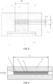
- the channel 1 corresponds to a space 6 (portion surrounded by a one-dot chain line) formed in such a manner that a projecting portion 4a of a channel main body projecting portion 4 is inserted into a recess portion 5a of a channel main body recess portion 5.
- a channel main body 7 (portion surrounded by a two-dot chain line) is constituted by the channel main body projecting portion 4 and the channel main body recess portion 5.
- the channel 1 is a channel having a length L in the flow direction.
- a direction along the length L is a longitudinal direction of the partition plate 2.
- the flow rate measurement is performed by a known method using transmission and reception of ultrasonic waves between the ultrasonic transducers 18 and 19. At this time, the ultrasonic waves pass through the divided channels 3 defined by the partition plates 2 of FIG. 3 .
- the partition plates 2 expand and contract by heat, and at the same time, the channel main body projecting portion 4 and the channel main body recess portion 5 which form the channel 1 also expand and contract. At this time, the expansion and the contraction in the longitudinal direction of the partition plate 2 shown in FIG. 4 are significant.
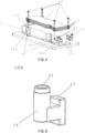
- upstream portions of the partition plates 2 are fixed to the channel main body projecting portion 4 by the fixed attaching portions 10a, but downstream portions of the partition plates 2 are slidably attached to the channel main body projecting portion 4 by the movable attaching portions 10b. Therefore, the partition plates 2 can freely expand and contract in accordance with the sliding of the leg portions 13 in the longitudinal direction of the partition plates 2. Thus, the deformation of the partition plates 2 in the thickness direction can be suppressed or prevented. Therefore, the uniformity of the height Ha between the partition plates 2 in FIG. 3 is maintained, and the flow in the channel is straightened. Moreover, the flow state of the fluid to be measured and the propagation state of the ultrasonic waves do not change. Therefore, the flow rate measurement accuracy is maintained.
- the fluid measurement channel apparatus 21 of the present embodiment includes: the channel 1 through which the fluid to be measured flows and which has a rectangular section; and the substantially rectangular partition plates 2 which are located so as to divide a short side of the channel 1; and the attaching portions 10 by which the partition plates 2 are attached and which are located at the upstream and downstream sides.
- One of the attaching portions 10 is the fixed attaching portion 10a fixed to the channel 1, and another attaching portion 10 is the movable attaching portion 10b that is slidable relative to the channel 1 in the longitudinal direction of the partition plates 2.
- the uniformity of the height Ha between the partition plates 2 can be maintained, and therefore, the flow state of the fluid to be measured and the propagation state of the ultrasonic waves do not change. Therefore, the flow rate measurement accuracy can be maintained.
- the ultrasonic flow meter 20 including the fluid measurement channel apparatus 21 even when the temperature of the fluid to be measured or the temperature of an environment where the ultrasonic flow meter 20 is located changes at the time of the flow rate measurement, the measurement accuracy is guaranteed.
- Embodiment 1 has described Embodiment 1 as an example of the technology disclosed in the present application.
- the technology in the present disclosure is not limited to this and is applicable to embodiments in which modifications, replacements, additions, omissions, and the like have been made.
- a new embodiment may be prepared by combining the components described in Embodiment 1.
- the attaching portion 10 at the upstream side is the fixed attaching portion 10a
- the attaching portion 10 at the downstream side is the movable attaching portion 10b
- the attaching portion 10 at the upstream side may be the movable attaching portion 10b
- the attaching portion 10 at the downstream side may be the fixed attaching portion 10a.
- the attaching portions 10 are located at two places that are the upstream side and the downstream side. However, the attaching portions 10 may be located at three places that are the upstream side, an intermediate place, and the downstream side, the fixed attaching portion 10a may be located at the intermediate place, and the movable attaching portions 10b may be located at the upstream side and the downstream side.
- the number of partition plates 2 is plural but may be one.
- the present disclosure even when the temperature of the fluid to be measured changes, the deformation of the partition plate in the measurement channel is prevented. Therefore, the measurement accuracy can be maintained.
- the present disclosure is applicable to fluid measurement channel apparatuses, and specifically to various flow meters, gas meters, and the like.
Landscapes
- Physics & Mathematics (AREA)
- Fluid Mechanics (AREA)
- General Physics & Mathematics (AREA)
- Electromagnetism (AREA)
- Measuring Volume Flow (AREA)
Applications Claiming Priority (2)
| Application Number | Priority Date | Filing Date | Title |
|---|---|---|---|
| JP2022079890 | 2022-05-16 | ||
| PCT/JP2023/018028 WO2023223985A1 (ja) | 2022-05-16 | 2023-05-15 | 流体計測用流路装置、及びこれを用いた超音波式流量計 |
Publications (2)
| Publication Number | Publication Date |
|---|---|
| EP4528232A1 true EP4528232A1 (de) | 2025-03-26 |
| EP4528232A4 EP4528232A4 (de) | 2025-08-20 |
Family
ID=88835527
Family Applications (1)
| Application Number | Title | Priority Date | Filing Date |
|---|---|---|---|
| EP23807587.3A Pending EP4528232A4 (de) | 2022-05-16 | 2023-05-15 | Strömungskanalvorrichtung zur fluidmessung und ultraschall-flussratenmesser damit |
Country Status (5)
| Country | Link |
|---|---|
| US (1) | US20250314510A1 (de) |
| EP (1) | EP4528232A4 (de) |
| JP (1) | JPWO2023223985A1 (de) |
| CN (1) | CN118900985A (de) |
| WO (1) | WO2023223985A1 (de) |
Family Cites Families (7)
| Publication number | Priority date | Publication date | Assignee | Title |
|---|---|---|---|---|
| JP2003270021A (ja) * | 2002-03-13 | 2003-09-25 | Tokyo Gas Co Ltd | 整流器 |
| JP3487307B1 (ja) * | 2002-11-01 | 2004-01-19 | 松下電器産業株式会社 | 流体の流れ計測装置 |
| JP4604520B2 (ja) * | 2004-03-10 | 2011-01-05 | パナソニック株式会社 | 流れ計測装置 |
| JP2008107234A (ja) * | 2006-10-26 | 2008-05-08 | Matsushita Electric Ind Co Ltd | 超音波式流体計測装置 |
| JP4986748B2 (ja) * | 2007-07-09 | 2012-07-25 | パナソニック株式会社 | 超音波式流体計測装置の多層流路部材 |
| JP5277911B2 (ja) * | 2008-11-28 | 2013-08-28 | パナソニック株式会社 | 流体計測用流路装置 |
| JP5793644B2 (ja) * | 2010-11-11 | 2015-10-14 | パナソニックIpマネジメント株式会社 | 超音波式流量計測装置 |
-
2023
- 2023-05-15 US US18/863,442 patent/US20250314510A1/en active Pending
- 2023-05-15 CN CN202380028335.1A patent/CN118900985A/zh active Pending
- 2023-05-15 WO PCT/JP2023/018028 patent/WO2023223985A1/ja not_active Ceased
- 2023-05-15 EP EP23807587.3A patent/EP4528232A4/de active Pending
- 2023-05-15 JP JP2024521917A patent/JPWO2023223985A1/ja active Pending
Also Published As
| Publication number | Publication date |
|---|---|
| JPWO2023223985A1 (de) | 2023-11-23 |
| CN118900985A (zh) | 2024-11-05 |
| US20250314510A1 (en) | 2025-10-09 |
| WO2023223985A1 (ja) | 2023-11-23 |
| EP4528232A4 (de) | 2025-08-20 |
Similar Documents
| Publication | Publication Date | Title |
|---|---|---|
| CN101943590B (zh) | 流量测定装置 | |
| EP3404371B1 (de) | Gaszähler | |
| JP6276054B2 (ja) | 熱交換器 | |
| EP3012593B1 (de) | Ultraschall-durchflussmessgerät | |
| EP2600116A1 (de) | Durchflussmessstruktur und durchflussmessvorrichtung | |
| CN100374827C (zh) | 流动计测装置 | |
| EP4528232A1 (de) | Strömungskanalvorrichtung zur fluidmessung und ultraschall-flussratenmesser damit | |
| EP3121550A1 (de) | Wärmetauscher | |
| EP3285047B1 (de) | Durchflussmessvorrichtung | |
| JP7402102B2 (ja) | リニアモータの冷却ユニット、リニアモータ、リニアモータの冷却ユニットの製造方法 | |
| JP6306434B2 (ja) | 超音波流量計 | |
| JP4893754B2 (ja) | 流体計測用流路装置及びこれを用いた超音波式流量計測メータ | |
| Gessel | On the Schur function expansion of a symmetric quasi-symmetric function | |
| EP4198438A1 (de) | Wärmetauscherstruktur | |
| WO2010061558A1 (ja) | 流体計測用流路装置 | |
| US10267664B2 (en) | Flow meter including two angled components forming channels | |
| US12123759B2 (en) | Ultrasonic flowmeter | |
| CN117686040A (zh) | 一种层流流量计 | |
| JP2023140538A (ja) | 熱式流量センサ | |
| US10981140B2 (en) | Catalytic reactor | |
| JP7215731B2 (ja) | 積層型反応器 | |
| JP2018159627A (ja) | 流量計測ユニット及びこれを用いた流量計 | |
| US11761804B2 (en) | Ultrasonic flowmeter having a partition plate dividing the flow path into a measurement flow path and a non-measurement flow path | |
| EP4484902A1 (de) | Ultraschall-durchflussmesser | |
| CN108700447B (zh) | 气量计 |
Legal Events
| Date | Code | Title | Description |
|---|---|---|---|
| STAA | Information on the status of an ep patent application or granted ep patent |
Free format text: STATUS: THE INTERNATIONAL PUBLICATION HAS BEEN MADE |
|
| PUAI | Public reference made under article 153(3) epc to a published international application that has entered the european phase |
Free format text: ORIGINAL CODE: 0009012 |
|
| STAA | Information on the status of an ep patent application or granted ep patent |
Free format text: STATUS: REQUEST FOR EXAMINATION WAS MADE |
|
| 17P | Request for examination filed |
Effective date: 20241031 |
|
| AK | Designated contracting states |
Kind code of ref document: A1 Designated state(s): AL AT BE BG CH CY CZ DE DK EE ES FI FR GB GR HR HU IE IS IT LI LT LU LV MC ME MK MT NL NO PL PT RO RS SE SI SK SM TR |
|
| A4 | Supplementary search report drawn up and despatched |
Effective date: 20250722 |
|
| DAV | Request for validation of the european patent (deleted) | ||
| DAX | Request for extension of the european patent (deleted) | ||
| RIC1 | Information provided on ipc code assigned before grant |
Ipc: G01F 1/00 20220101AFI20250716BHEP Ipc: G01F 1/66 20220101ALI20250716BHEP Ipc: G01F 15/14 20060101ALI20250716BHEP |